
Abstract
The Lamb wave imaging approach based on adaptive beamforming method, notably the minimum variance distortionless response beamforming algorithm, is analyzed to explain its serious performance degradation or even complete invalidation, when the scattering signals generated by damages are coherent. It is demonstrated that in such case, the covariance matrix of the received scattering signals becomes rank-deficient, and when decomposed into the description form of the array manifold matrix left and conjugate right multiplied by a matrix
Introduction
Damage monitoring in plate-like structures is crucial across a plethora of industries, including petrochemical, nuclear power, shipbuilding, machinery, and aerospace, among others.1–3 The advantages of Lamb waves for superior performance in detecting and localizing damage in plate-like materials have been extensively documented. It possesses the ability to propagate over extensive distances with minimal attenuation, all the while retaining its sensitivity to even the slightest structural damages.4–6 Such characteristics make it highly suitable for structural health monitoring (SHM). Several advanced imaging techniques based on Lamb waves, including tomography imaging and full waveform inversion imaging, have been proposed for SHM.7–13 Although these techniques provide excellent performance and accuracy in generating thickness maps of corrosion damage, their computational cost is generally high. This is mainly due to their significant dependence on the density of transducers, resulting in bulky and expensive hardware that can hinder the practical application of these techniques. 14
The combination of Lamb wave imaging with array signal processing techniques, such as beamforming techniques, has gained significant attention due to their potential applications. The data-independent delay-and-sum (DAS) beamformer has been widely utilized as a simple and practical beamforming algorithm in previous studies.15–19 However, the DAS beamformer has been noted to have limitations in terms of low resolution and high sidelobes. This can lead to the production of poor imaging quality in many imaging scenarios where higher quality is required. To address this, adaptive beamforming algorithms have been integrated into Lamb wave imaging with the aim of enhancing imaging resolution and mitigating imaging artifacts. By adaptively weighting the signals from each sensor in the array, these algorithms can greatly enhance the imaging results compared to the DAS beamformer. The minimum variance distortionless response (MVDR) beamformer stands as a commonly utilized beamforming algorithm, revered for its optimality in maximizing the signal-to-interference-plus-noise ratio (SINR) of array outputs. Through spatially distributed arrays, the MVDR algorithm initially introduced by Michaels et al. in Lamb wave-based damage monitoring showcased superior performance over DAS. 20 Xu et al. 21 proposed a Lamb wave imaging technique employing weighted sparse decomposition coefficients to achieve minimum variance for the nondestructive evaluation of laminated composite plates. Hua et al. 22 replaced the commonly used signal amplitudes with correlation coefficients to conduct damage imaging via the MVDR algorithm. Unfortunately, when two or more damages are present, the scattering signals produced by damages at different locations may exhibit coherence. For example, when multiple damages are located on the same line or have similar shapes, the scattering signals they generate may reinforce or interfere with each other, resulting in a coherent phenomenon. Previous studies have shown that the effectiveness of the MVDR beamformer is restricted in scenarios involving such coherent signals. Despite numerous techniques have been investigated to enhance the robustness of adaptive beamforming algorithms, such as the Toeplitz matrix reconstruction algorithm, 23 spatial smoothing, 24 and other robust beamforming algorithms,25–27 these methods cannot overcome the inherent drawback of spatial smoothing algorithms, which is the trade-off between sacrificing the effective aperture of the array for achieving robustness to coherent interference. 27 Additionally, the MVDR beamformer is designed to maximize the SINR of the array output, and thus theoretically requires the calculation of the interference-plus-noise covariance matrix (INCM). However, in most cases, the INCM is unknown, and the sample covariance matrix is usually used as a substitute. When there are strong damaged scattering signals exactly at the expected angle of the beam, employing the sample covariance matrix instead of the INCM will result in significant performance degradation of the MVDR beamformer. 28 There have also been studies that incorporate the multiple signal classification (MUSIC) algorithms into Lamb wave imaging on plate-like structures. An approach for imaging and evaluating micro-crack damage utilizing nonlinear Lamb waves was introduced, drawing from the MUSIC and beamforming algorithm. 29 Additionally, Fan et al. 30 proposed a time reversal-based focusing MUSIC algorithm for damage localization without requiring a baseline. Similar to the MVDR beamformer, these methods also utilized the sample covariance matrix as a substitute for the INCM, making them vulnerable to coherent signals. Moreover, in these methods, utilizing the MUSIC algorithm requires prior knowledge of the number of damages within the structure, which can be a difficult task.
In order to deal with these situations, the conventional adaptive beamforming Lamb wave imaging approach is analyzed to explain its serious performance degradation or even complete invalidation in the presence of coherent scattering signals. Then, after a method for fitting the INCM using a weighted least squares criterion is proposed, an effective INCM matrix reconstruction-based Lamb wave imaging approach for damage identification of plate-like structures is presented. The validity of the proposed algorithm is confirmed by comparing damage imaging results of various methods in numerical simulations and experiments.
The subsequent sections of this article are structured as follows. The monitoring model of the far-field assumption using a beamforming algorithm with a uniform linear receiver array for monitoring the health of plate-like materials is formed, and a problem description is provided in ‘Problem description’ section. The INCM reconstruction-based beamforming algorithm using a weighted least squares criterion is presented in detail in the next section. In ‘Numerical simulation’ and ‘Experimental investigation’ sections, the proposed method is systematically compared with conventional approaches such as DAS and MVDR algorithms through various scenarios. Comprehensive discussions and analyses of imaging results follow. Finally, ‘Conclusion’ section drawn from the study are provided.
Problem description
Lamb wave imaging with MVDR beamformer
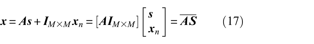
This study investigates the application of active Lamb waves for damage monitoring of plate-like structures. An actuator transducer is employed to stimulate ultrasonic Lamb waves in the structure. To mitigate the impact of dispersion and multimode effects in ultrasonic guided waves, narrowband signal excitation is utilized. Upon encountering damage in plate-like structures, Lamb waves produce scattering signals which are considered as the secondary wave source. Subsequently, scattering signals are received by a uniform linear transducer array S1, S2, …, and SM, respectively. Before imaging for the damages, it is necessary to subtract baseline signals obtained under non-destructive conditions before inspecting the plate-like structures from the received scattering signals. Assuming that N scattering signals are incident from directions

where
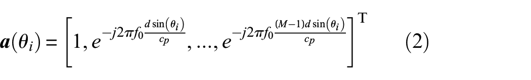
where f0 represents the central frequency of the Lamb wave. cp denotes the phase velocity of the Lamb wave, whose value equals to w/k(w), where w = 2πf refers to the angular frequency, and k(w) represents the wavenumber of the Lamb wave under the assumption of a single Lamb mode when disregarding the dispersion effect. The superscript T indicates the transpose operation.
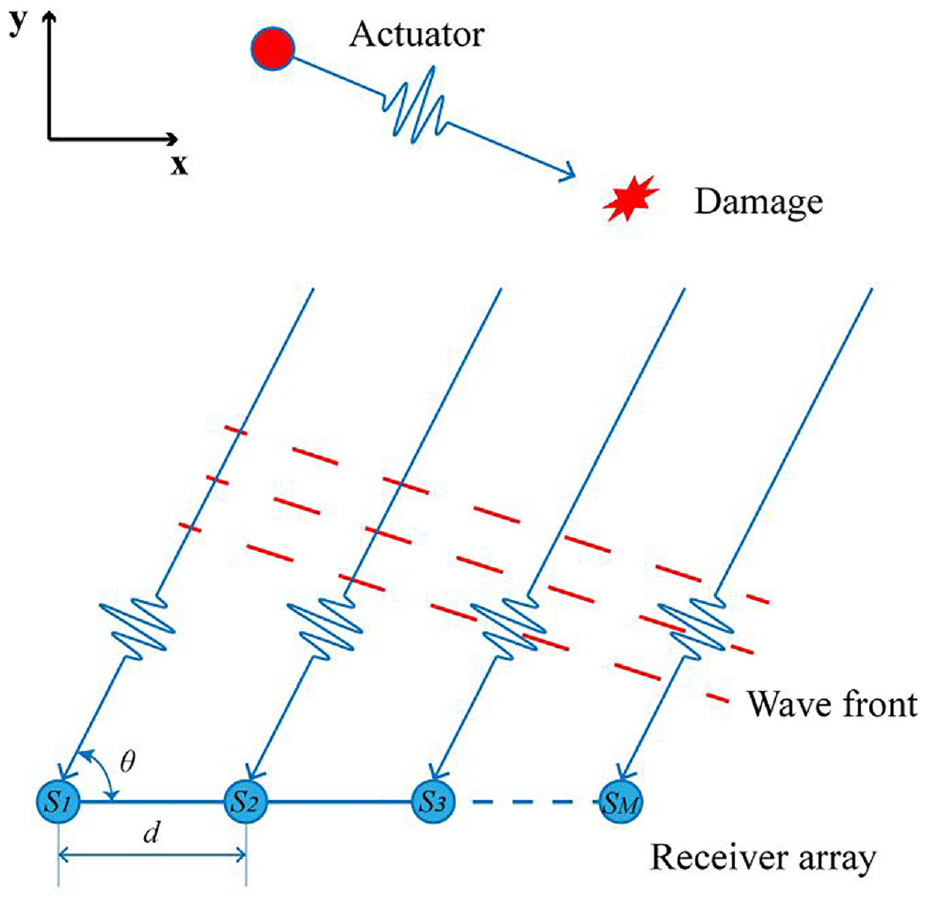
The schematic illustration of the conventional far-field monitoring model with a uniform linear receiver array.
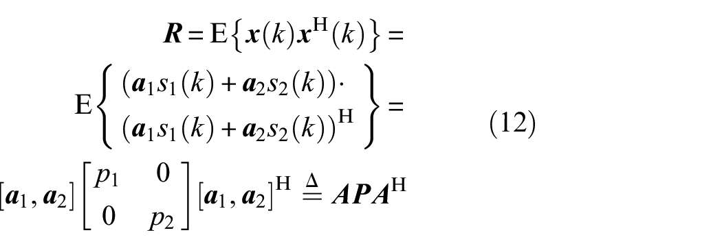
According to Equation (1), the covariance matrix of

where the superscript H indicates the conjugate transpose and
where
When using the beamforming damage imaging algorithm, for each discrete scanning point within the inspection region, the pixel value of the coordinate (x, y) is computed as the amplitude of the beamformer output.
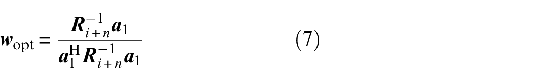
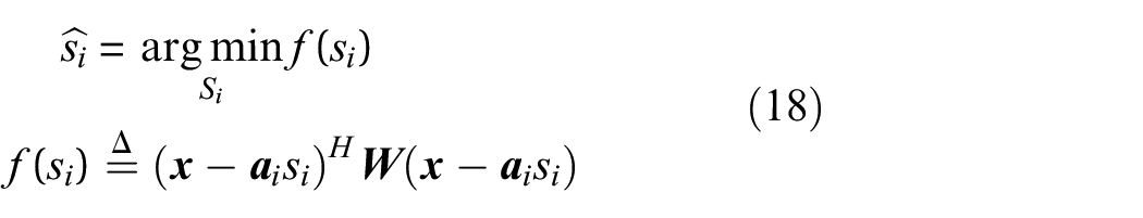
As a typical adaptive beamformer, the objective of MVDR beamformer is to preserve the power of the desired output signal while minimizing the power output of interference and noise, which can be achieved by solving a convex optimization problem as outlined in Darzi et al. 32 :
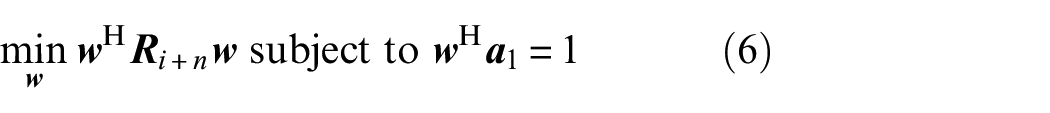
The above Equation (6) is solve by:
where

In practical scenarios, acquiring
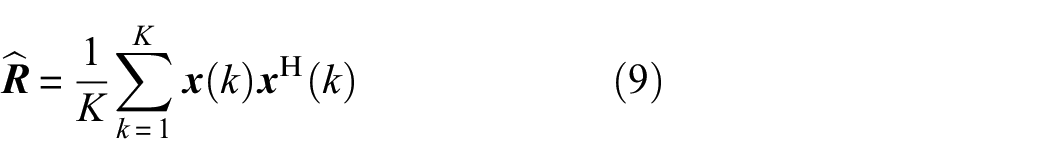
where
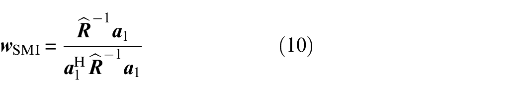
According to the previous studies,33–41 the performance of the beamformer obtained from Equation (10) will be severely degraded when the sampling covariance in Equation (9) contains the SOI at high signal-to-noise ratio (SNR). The following analysis will show that when there is coherent interference between sources in Equation (1), the performance of Equation (10) will also suffer severely, even fail completely.
Coherent interference analysis
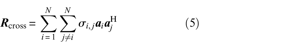
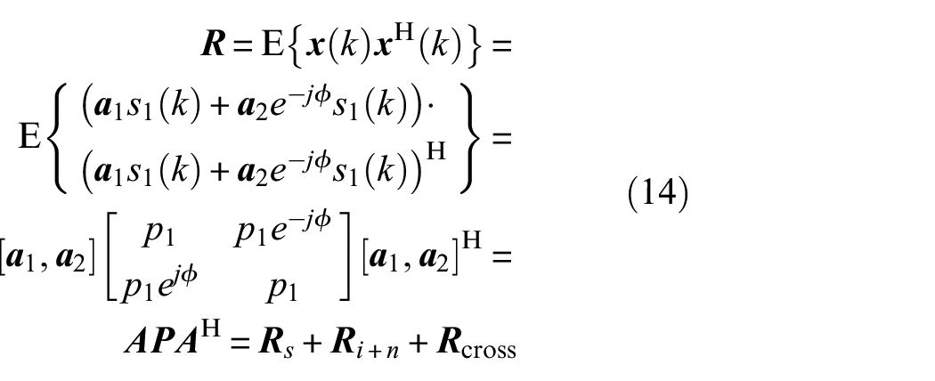
For ease of analysis, assume that there are two damages in plate-like structures, where two scattering signals

When the
where
If

Hence, the sample covariance matrix is
where
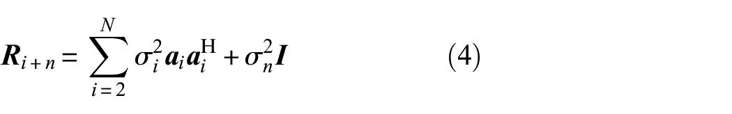
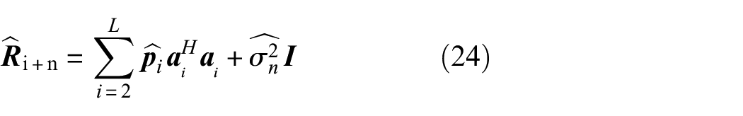
When the scattering signals are coherent, if INCM shown in the following formula can be reconstructed, obviously the beamformer designed thus can be robust to the coherent scattering signals.
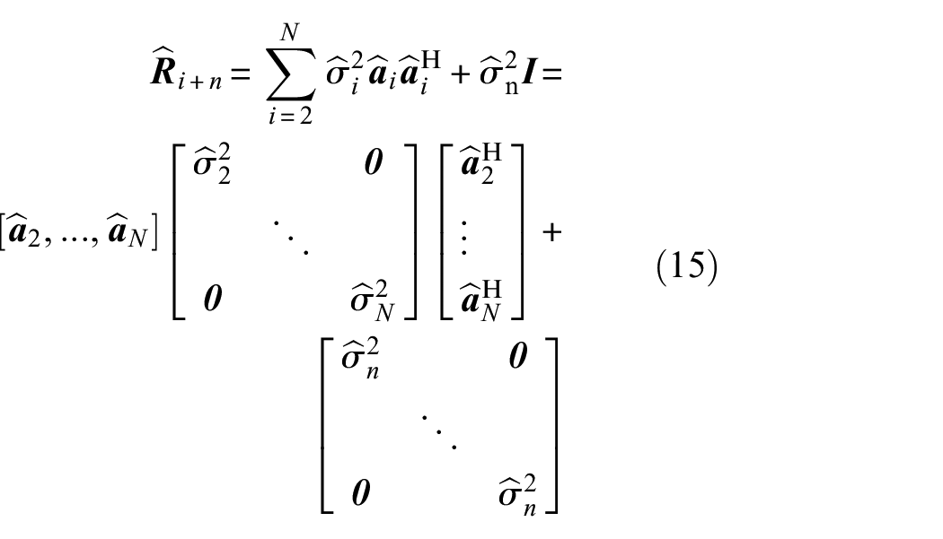
where
INCM fitting method using a weighted least squares criterion
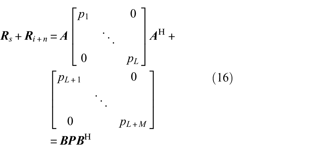
From the aforementioned analysis, it can be inferred that if the INCM described by Equation (15) can be fitted, it would be possible to design a robust beamformer for coherent scattering signals. To reconstruct
For the aim of obtaining
where
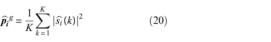
In order to estimate
where
When

where
Assuming that the noise power is equal, one has:
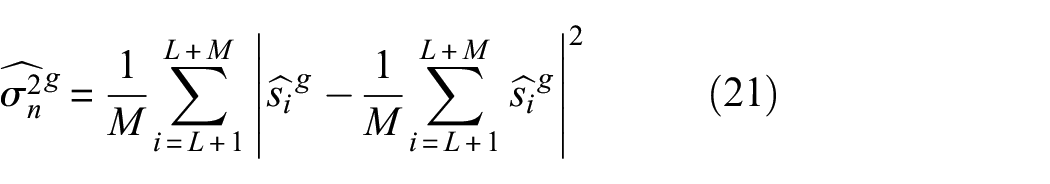
Then,
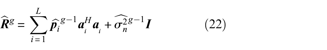

Note that Equations (20), (21) and (22) are performed during each iteration on the basis of the estimation of the covariance matrix fit of the previous iteration. To address the issue of rank deficiency in coherent interference and considering that the main influence of rank deficiency is the inverse process. Therefore, we initialize

The iterative process is updated by using the results of the previous iteration to obtain
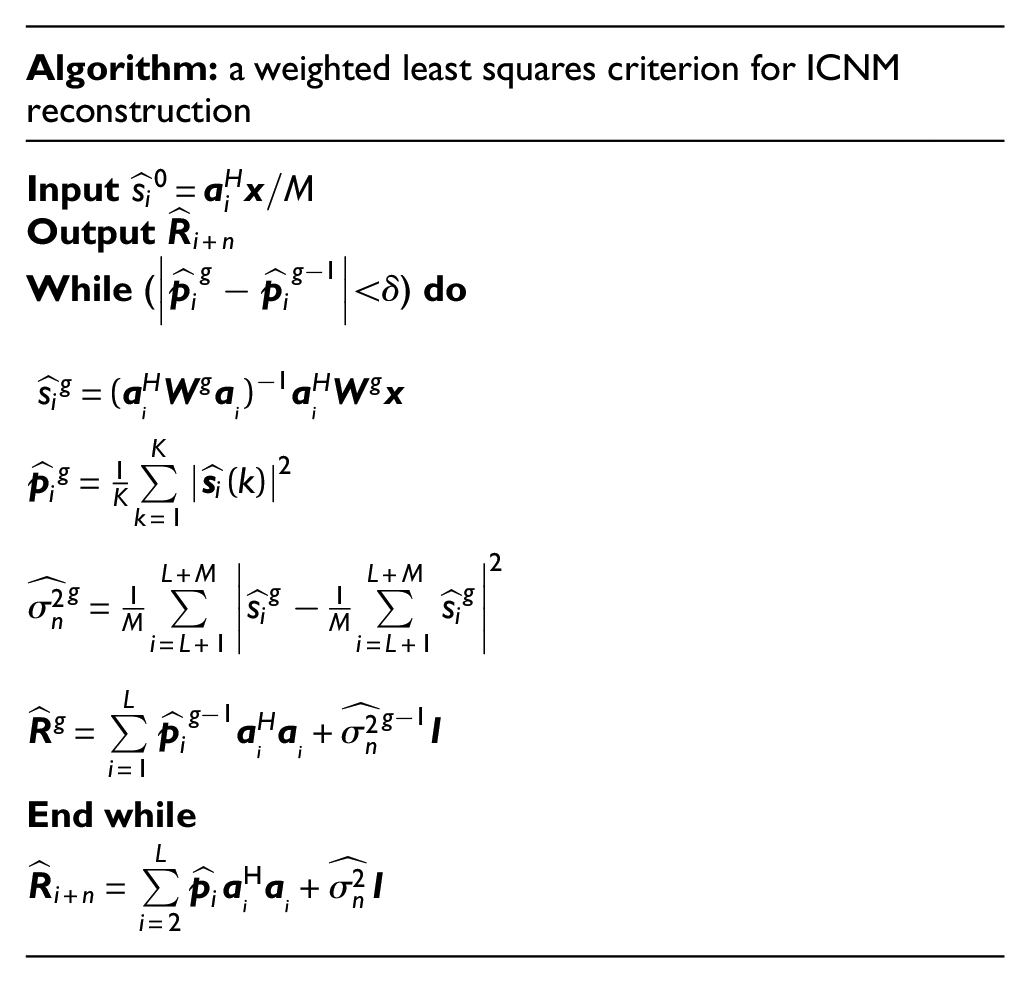
After the estimation of the INCM required, the MVDR beamformer according to Equation (7) is then conducted to perform damage imaging. The complete iterative process is illustrated in the following figure.
Numerical simulation
Aiming at verifying the performance of the proposed method, the numerical simulation is performed on a three-dimensional aluminum plate by using the optimized finite difference (FD) computation method via Devito-3.1.0. 45 The dimensional parameters of the plate are 1000 mm × 1000 mm × 2 mm, and its material parameters are written in Table 1. For computational efficiency, an element size of 2 mm × 2 mm is chosen in the finite element model. Figure 2 depicts the configuration of the actuator and receiver array, comprising six transducers with a spacing of 12 m.
Material parameters of the aluminum plate.
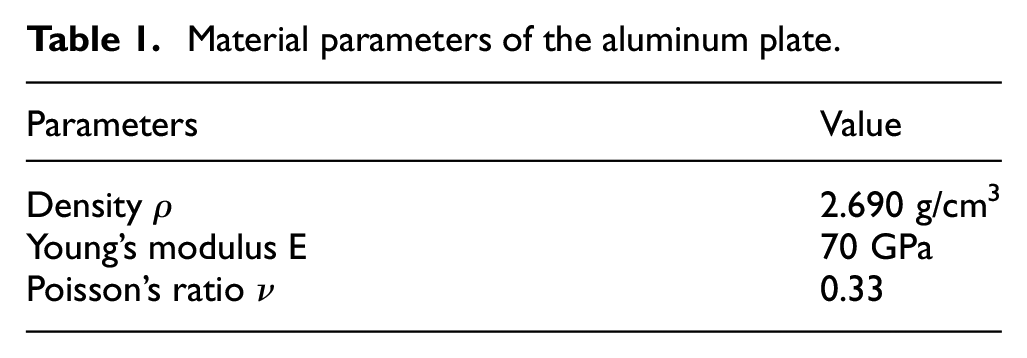
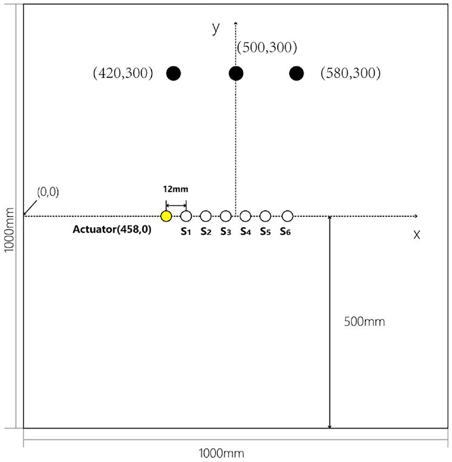
Plate configuration in the numerical simulation.
In the simulation, the actuator produces a five-period windowed burst sine signal by Hanning envelope modulation. It is a standard narrow band signal whose carrier frequency is 40 kHz. Under the circumstances, the predominant Lamb wave signals are primarily of the A0 mode, characterized by a group velocity of 1580 m/s and a phase velocity of 865 m/s, as indicated by the dispersion curve. Additionally, Gaussian white noise is incorporated into the numerical simulation.
Simulations are conducted under various conditions in terms of coherent sources and SNRs to validate the effectiveness of the proposed method.
Coherent scattering signals
The scattering Lamb wave signals originating from damage are recognized to exhibit high coherence, posing a challenge for the MVDR algorithm, which struggles to manage correlated signals effectively. To demonstrate the necessity of reconstructing the INCM to overcome this limitation, the performances of the MVDR algorithm utilizing the sample covariance matrix (with and without spatial smoothing) and the INCM reconstructed by the proposed algorithm are compared. Two damages in the form of through-holes measuring 20 mm in diameter at the positions of (420, 300 mm) and (580, 300 mm) on the plate are depicted in Figure 2. The damage imaging results of different methods are depicted in Figure 3 under the SNR of 10 dB. As we can see in the imaging results, although the MVDR algorithm helps improve the resolution significantly in Figure 3(b) compared with the DAS in Figure 3(a), the damage imaging results are confusing since the scattering signals from these two damages are highly correlated. The spatial smoothing with a subarray length of 2 is conducted in Figure 3(c) which helps avoid signal cancellation, whereas the performance encounters serious degradation even worse than DAS one as the array size reduces to 2. The damage imaging result using the INCM reconstructed by the proposed algorithm in Figure 3(d) not only overcomes the limitation of the MVDR algorithm in handling the correlated signals but also preserves its excellent performance.
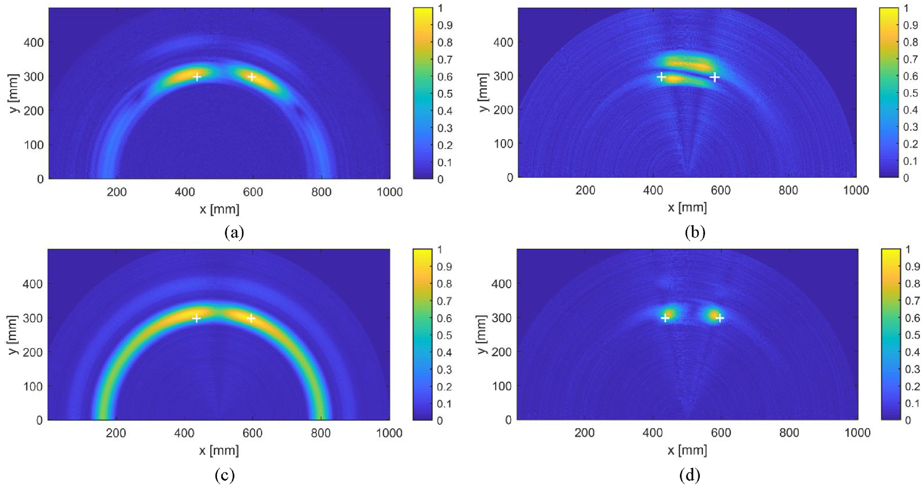
The results of damage imaging at the SNR of 10 dB: (a) DAS; (b) MVDR; (c) MVDR (spatial smoothing with subarray length of L = 2); (d) MVDR (using the INCM reconstructed by the proposed algorithm).
Signal-to-noise ratios
Another major problem of previous studies which use a sample covariance matrix to perform MVDR imaging is that the imaging performance will be seriously affected by the SNR. As for the DAS method, it is known that the imaging results improve as the SNR increases, and the MVDR should be the same. However, due to the presence of the desired signal in the sample covariance matrix, the imaging results may not improve as expected, especially when the desired signal is strong. We conduct simulations under different SNRs utilizing the sample covariance matrix and the INCM reconstructed by the proposed algorithm respectively. In these simulations, damage is represented as a through-hole measuring 20 mm in diameter located at the coordinate (500, 300 mm) on the plate as illustrated in Figure 2.
The results of damage imaging under different SNRs are depicted in Figure 4. As observed, imaging quality improves with increasing SNR up to 10 dB. However, when the SNR continues to increase, the imaging results degrade since the desired signal cannot be ignored, even failing to identify the damage when the SNR reaches 20 dB as in Figure 4(g). By contrast, after using the INCM reconstructed by the proposed algorithm which removes the desired signal, the imaging results maintain excellent performance over a wide range of SNRs. Meanwhile, Figure 5 illustrates the relationship between the output SINR and the input SNR of the MVDR beamformer based on INCM and the sample covariance matrix. The figure demonstrates that when the input SNR is low, the output SINR of the MVDR beamformer based on the INCM closely approximates the theoretical optimal value, akin to the MVDR beamformer employing the sample covariance matrix. When the input SNR is higher than 5 dB, the output SINR of the MVDR beamformer based on the INCM still maintains excellent performance, which is not affected by the desired signal components as the MVDR beamformer utilizing the sample covariance matrix. Figure 6 illustrates the normalized output power of different methods when the scattering signals from the two damages are highly correlated, providing a clearer demonstration of the superior performance of the proposed method. The normalized output power using the INCM reconstructed by the proposed algorithm shows its excellent performance in handling the correlated signals.
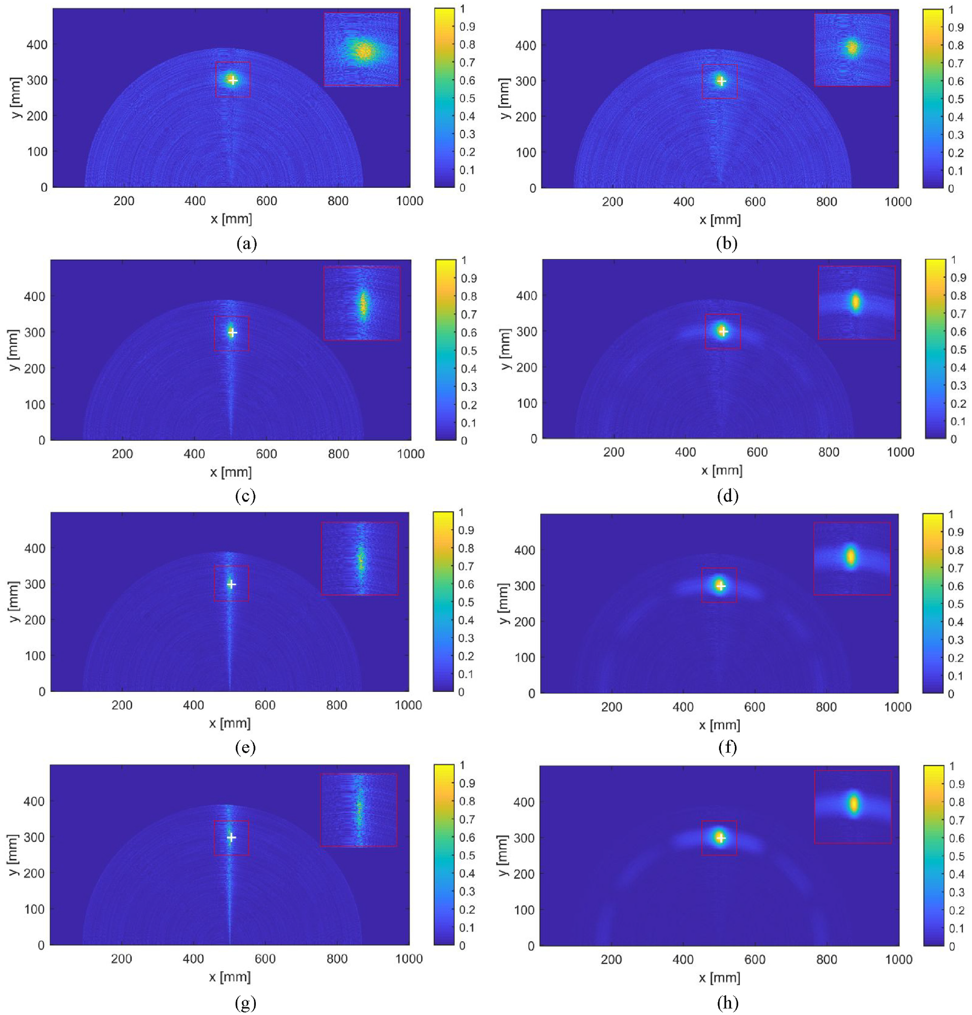
The results of damage imaging: (a, c, e, and g) the MVDR method using sample covariance matrix under SNR of 0, 10, 15, and 20 dB, respectively; (b, d, f, and h) the MVDR method using the INCM reconstructed by the proposed algorithm under SNR of 0, 10, 15, and 20 dB, respectively.
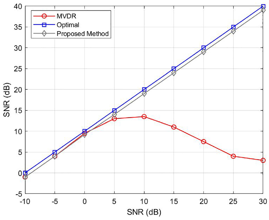
The SINR of MVDR beamformers under various values of SNR.
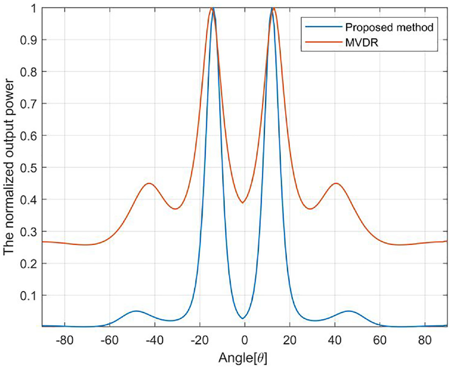
The normalized output power of the MVDR method under coherent signals.
Experimental investigation
In this section, an experimental system is built to further validate the proposed method, which is conducted on an aluminum plate with dimensional parameters of 1000 mm × 1000 mm × 2 mm as depicted in Figure 7. The detailed configuration of the experimental setup is illustrated in Figure 7(a). During the experiment, a five-period windowed burst sine signal whose carrier frequency is 40 kHz by Hanning envelope modulation is utilized as Lamb wave excitation, similar to that adopted in the numerical simulation. This signal is generated by the Agilent 33220A arbitrary function generator under the control of the master computer. Subsequently, the excitation signal is amplified by a linear broadband power amplifier AG 1021, whereas data are captured by an Agilent MSO6052A oscilloscope with a sampling frequency of 1 MHz. To simulate damage on the aluminum plate, cylindrical mass blocks measuring 2 cm in diameter are utilized. The addition of mass can theoretically alter the boundary conditions of wave propagation within the loaded region, mimicking the effects of cracks and holes. Additionally, adjusting the position of the mass blocks allows for the convenient simulation of different damage positions.
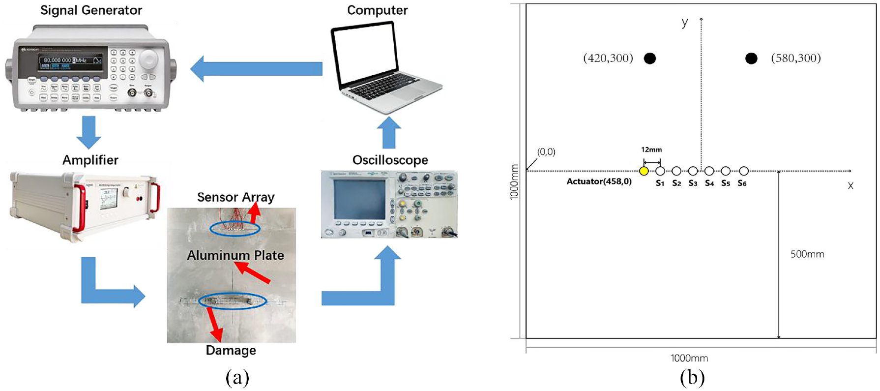
Experimental layout: (a) practical photo of the measurement system; (b) aluminum plate configuration with coherent sources.
Coherent sources
To assess the impact of the coherent sources on imaging results, two damages are set on the aluminum plate with positions of (420, 300 mm) and (580, 300 mm) as illustrated in Figure 7(b). The transducer array’s received response signals, depicting both the direct signal and boundary echo signal, are presented in Figure 8(a). Subsequently, scattering signals are obtained through subtraction of the baseline signals, yielding a clear representation as shown in Figure 8(b). The performances of DAS, the MVDR algorithm using sample covariance matrix (with and without spatial smoothing) and the INCM reconstructed by the proposed method algorithm, and the results of damage imaging are shown in Figure 9. As we can see from the imaging results, although the imaging result of DAS in Figure 9(a) has poor resolution, it is not affected by the correlated scattering signals. However, the MVDR algorithm is seriously affected by the coherent sources, whose damage imaging results are so confusing that it even fails to recognize the damages properly in Figure 9(b). The spatial smoothing with a subarray length of L = 2 is conducted to help avoid signal cancellation, while the performance degrades seriously even worse than the DAS one as the array size reduces to 2, as evident in Figure 9(c). The imaging result using the INCM reconstructed by the proposed method algorithm in Figure 9(d) not only overcomes the limitation of the MVDR algorithm in handling the correlated signals but also maintains the excellent performance of MVDR.
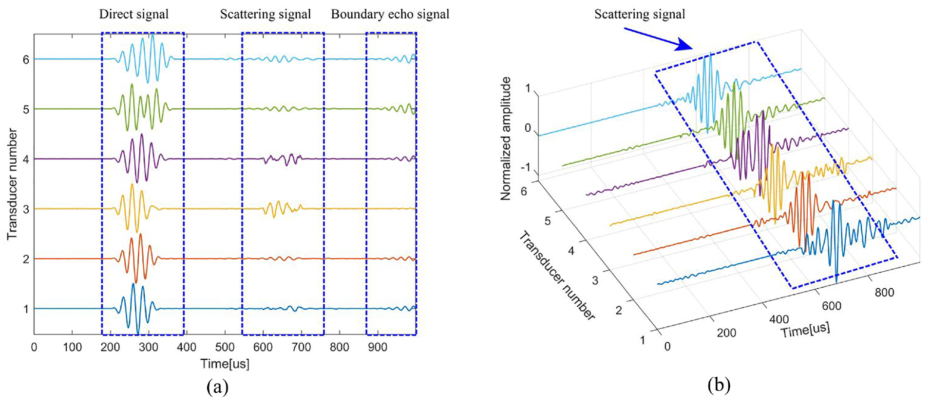
The impact of the coherent source: (a) response signals received by transducer array; (b) scattering signals.
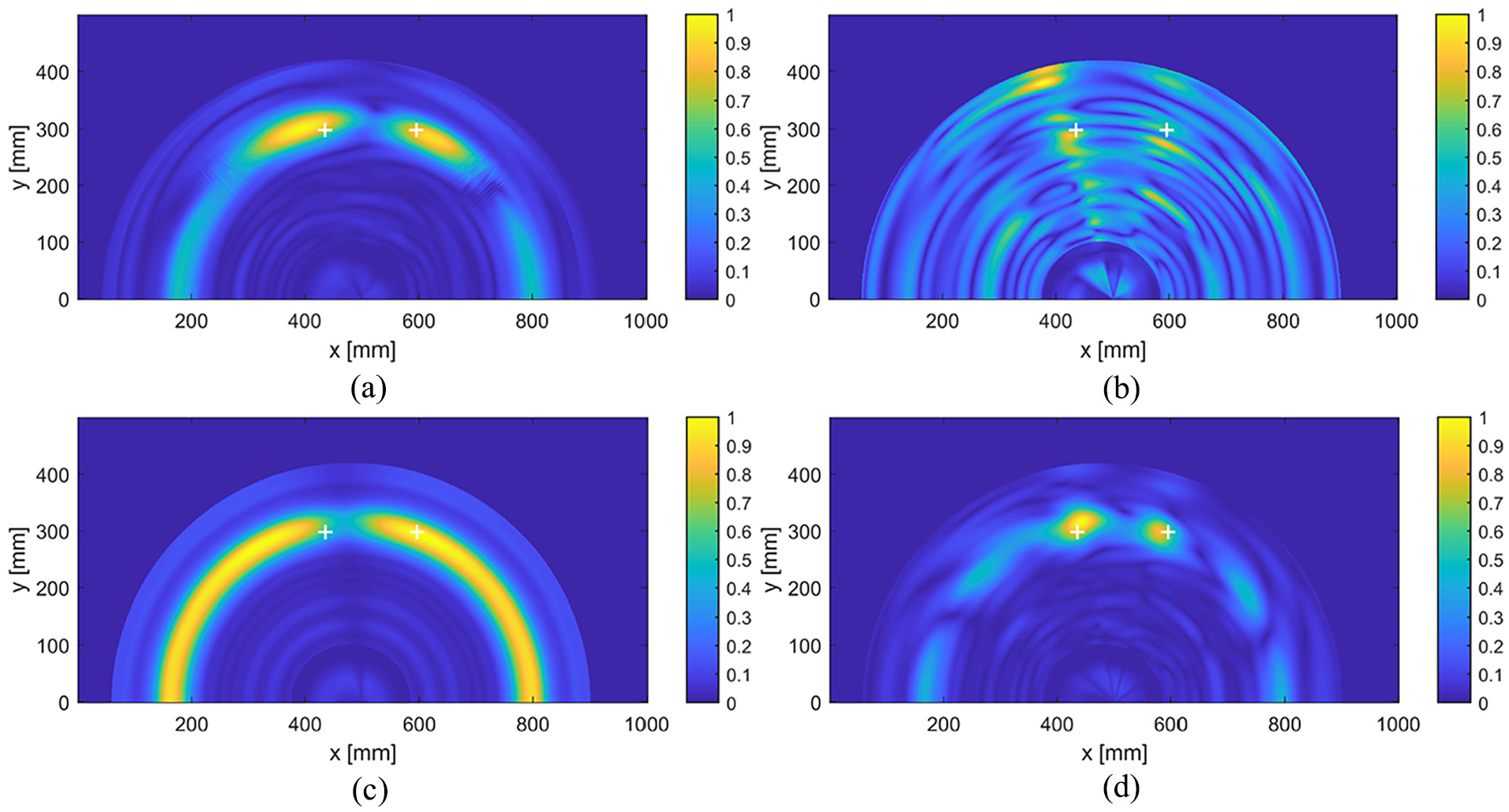
The results of damage imaging: (a) DAS; (b) MVDR; (c) MVDR (spatial smoothing with subarray length of L = 2); (d) the proposed method.
Discussions
Regarding the issue of array spacing, we utilize a uniform linear array that employs an adaptive beamforming method. This approach is effective only if the spacing between the array elements is less than or equal to half the wavelength. In our simulations and experiments, we set the element spacing to 12 mm, which corresponds exactly to half a wavelength. If the element spacing exceeds 12 mm, it can lead to a grating lobe effect, resulting in imaging artifacts. Conversely, if the element spacing is less than 12 mm, the aperture of the array will decrease, causing an increase in the width of the main lobe, which can affect positioning accuracy. Therefore, selecting an appropriate element spacing is crucial for ensuring imaging quality.
For imaging methods such as beamforming techniques like MVDR, the imaging performance primarily depends on the width of the main beam, which is determined by the excitation frequency. Therefore, the higher the excitation frequency, the better the imaging quality. Additionally, a higher power of the excitation signal will result in a higher SNR of the scattered signals from the damage, further improving the imaging quality.
Monitoring defects in metal plates may be less critical compared to other structures, but it is particularly crucial in composite materials. This is because composites have complex mechanical properties and structural characteristics that are more susceptible to environmental and operational conditions, leading to defects such as delamination and cracks. Meemary et al. mentioned that sensor embedding techniques and layout design present greater challenges in composites, requiring careful consideration to minimize the impact of sensors on mechanical performance while ensuring effective monitoring. 46 Through this article, we can understand the importance of sensor embedding techniques and configuration optimization in composites for monitoring purposes. We believe that sensor embedding techniques and configuration optimization in composite materials are critical for monitoring and are more challenging than subsequent signal acquisition and processing.
Our imaging method has a processing time of 1 min, which allows it to be done online for SHM. In the aerospace sector, our method can be used to detect potential defects in the metal plates of aero-engine blades and wings, thereby ensuring flight safety. In the oil and gas industry, this technology is employed to monitor the corrosion status of pipelines and storage tanks. Additionally, in bridges and other critical infrastructure, our method can detect damage and corrosion in steel structures, ensuring their long-term safety. However, it is important to note that currently, our method can only locate the position of the damage and cannot monitor specific details, such as the thickness of corrosion.
Conclusion
The performance of the Lamb wave imaging approach based on adaptive beam-forming methods, specifically the MVDR algorithm, is seriously degraded or invalidated when coherent scattering signals are generated by damages. This degradation is caused by the rank deficiency of the covariance matrix of the received scattering signals, which can be decomposed into the array manifold matrix multiplied by a non-diagonal matrix
Footnotes
Declaration of conflicting interests
The authors declared no potential conflicts of interest with respect to the research, authorship, and/or publication of this article.
Funding
The author(s) disclosed receipt of the following financial support for the research, authorship, and/or publication of this article: This work was supported by the National Natural Science Foundation of China under Grant 12374431.