
Abstract
This article presents the health monitoring of carbon fiber-reinforced plastic (CFRP) structures using a data-driven deep transfer learning approach to facilitate mapping signal features to damage categories. Simulations were conducted on composite material specimens with delamination damage, with validation performed using laboratory-derived CFRP damage experimental data. Continuous wavelet transform was employed to process Lamb wave signals recorded from a specified sensor network on the composite material panel, extracting time–frequency scale representations. A cross-workpiece deep transfer learning (CWTL) model was proposed to address the interdependence of the machine learning (ML) model on a large set of labeled damage data for different composite material structures. The CWTL, by seeking an appropriate initial range with minimal data, alters the direction of gradient descent, thereby identifying initial parameters more sensitive to the task. This process allows the ML model to fit to a limited damage dataset quickly. To assess the robustness of this method, considering environmental variability as well as damage localization and quantification, further extensions of the study were explored. The results demonstrate the efficacy of CWTL in accurately classifying both undamaged and delaminated damage categories, with high accuracy, suggesting the ML model’s potential for practical applications in such structural frameworks.
Keywords
Introduction
Due to its characteristics such as lightweight, high strength, and corrosion resistance, carbon fiber reinforced plastic (CFRP) material structures find extensive applications in aerospace and other fields. 1 However, owing to the particular nature of their operational environment, composite material structures are susceptible to unsafe factors during service, such as high temperatures, cyclic loads, and impacts. 2 With the deepening of the concept of structural health monitoring, and in order to ensure the demands of safe and stable operation of structures, it is necessary to research intelligent damage diagnosis. 3 Intelligent damage diagnosis involves the application of sophisticated algorithms and computational methods, including machine learning (ML) and artificial intelligence, to automatically detect, assess, and classify damage in materials or structures. This approach integrates sensor data, such as those from Lamb waves or other monitoring systems, with advanced analytical techniques to identify damage patterns, predict potential failures, and guide maintenance decisions. By utilizing data-driven models and adaptive learning processes, intelligent damage diagnosis aims to enhance the precision and reliability of damage assessment beyond traditional methods, enabling proactive and efficient management of structural health.4–6 Various detection methods for damage to composite material structures have been studied, including methods based on vibration signals,7–10 methods based on fiber optic grating sensing identification,11–13 and methods for damage localization based on wave signals.14–16 Although traditional mechanics-based monitoring methods can provide relatively high accuracy in small strains and linear ranges, they typically require precise material properties and structural geometric information and are only applicable to specific types of damage or stress conditions. In contrast, ML-based methods can bypass these shortcomings and demonstrate significant potential.17,18
With the development of artificial intelligence technology, the combination of signal-based methods and ML has shown potential in damage detection.19–21 Bang et al. 22 applied the Region-based Convolutional Neural Network (R-CNN) object detection network for defect monitoring in composite materials using thermal images. To improve detection speed, the model directly extracted image features from the network and predicted defect categories and locations through the prediction head. When using the Inception V2 module, the model achieved a maximum accuracy of 75%. Li et al. 23 proposed a YOLOv4-based monitoring model for impact damage localization in CFRP. This model enhanced the image feature extraction capability of infrared signals by introducing a One-Dimensional Convolutional Neural Network (1D-CNN), thereby improving the ability to distinguish different types of damage. Xu et al. 24 introduced a full-scale enhancement convolutional neural network for identifying one-dimensional signals obtained using terahertz (THz) detection technology. This network utilized multiple one-dimensional convolutional kernels of different sizes to enhance the network’s multiscale signal feature extraction capability. The ML model transformed the problem of delamination depth detection into a multiclassification problem and achieved final defect localization by classifying THz signals point by point. Qin et al. 25 collected data on defects such as CFRP debonding and delamination using an infrared thermal imaging camera and evaluated the impact of pretrained weights on four networks: Fully Convolutional Network (FCN), U-Net, Seg-Net, and long short-term memory network. The results indicated that pretrained weights obtained from other datasets effectively improved the network’s accuracy on small sample datasets. Tabernik et al. 26 proposed a multiscale deep CNN network. The proposed method involved two steps: first, segmenting material cracks, and then classifying the crack types. The segmented output was used as an additional input to the decision network for classification. This network required only a small number of samples and did not require pretraining. The ML model achieved a final prediction accuracy of 99.9% on the composite material dataset.
Effective damage monitoring in composite materials requires ML models trained on well-annotated datasets. However, ML models developed for specific composite structures often lack generalization and are not applicable to others. Detecting damage in composite materials typically demands a large amount of labeled data and custom neural networks, but these requirements are challenging to meet due to the complex operating conditions of composite structures, such as temperature variations, humidity, and external loads. Additionally, the complex and diverse nature of damage types and degrees in composite materials, resulting from their unique anisotropic properties and heterogeneous composition, makes thorough structural health monitoring of a composite material structure workpiece, encompassing all possible damage modes and severity levels, particularly challenging. It is difficult to complete comprehensive data collection, label creation, and new ML model construction work. Therefore, conducting research on damage diagnosis methods that can be applied across different composite material workpieces (cross-workpiece), with a small number of data samples, extracting damage feature representations from limited training data, and accurately identifying the current damage status of the workpiece even under varying operating conditions are the core challenges in damage diagnosis, aimed at reducing the ML model’s reliance on labeled data samples.
To overcome the aforementioned challenges, the method of transfer learning has been applied to the health monitoring of composite material structures, aiming to leverage the knowledge from the source domain to improve the performance in the target domain.27–31 Azad et al. 32 proposed a pretrained transfer learning method based on CNN, using the ResNetV2 model to address data scarcity issues. The RNV2 model does not require developing a model from scratch; it only needs fine-tuning on the target composite material dataset. Validation results indicate that even under limited data conditions, the pretrained RNV2 model can effectively perform SHM for CFRP composites. Liu et al. 33 integrated monitoring data with physical mechanisms and proposed a robust and generalizable damage detection framework for CFRP composite structures. Numerical methods were used to establish a physical model of the composite structure to generate data under various damage conditions. By incorporating domain adaptation and domain adversarial training into the transfer learning (TL) model, domain-invariant damage features can be transferred from the source domain to the target domain. Xu et al. 34 introduced a data-driven TL model for locating damage area coordinates in plate-like structures with complex geometric features such as rivets and grooves. Due to the limited availability of labeled target data, the TL model not only focuses on the prediction accuracy of individual samples but also aims to preserve the global properties of the dominant conditional distribution of the target data. Chen et al. 35 proposed a CFRP composite structure damage detection method based on few-shot TL. This method utilizes knowledge learned from an imbalanced data domain generated from a single CFRP composite sample and applies this knowledge to other data domains generated by CFRP samples with different structural characteristics. Xu et al. 36 presented a fatigue damage diagnosis method for composites based on deep TL, transferring the physical mechanisms provided by numerical models to the diagnosis of real monitoring data. By adjusting the data distribution of corresponding categories in the simulated dataset and the experimental dataset, subdomain adaptation is achieved, thereby integrating the physical mechanisms provided by the numerical model with the monitoring data. This indicates that TL methods demonstrate better generalization when faced with the problem of a limited number of labeled fault samples. Moreover, TL provides new ideas for damage diagnosis in different workpieces and operating conditions. However, at the same time, such methods still have certain limitations in engineering practice, assuming that the target operating conditions are known and that there is certain data available for TL, such as a small number of labeled damage data or unlabeled data containing workpiece damage information.37–39
To address the aforementioned issue, this article proposes a method for diagnosing delamination damage in composite materials that integrates deep CNN networks with TL. The method is designed from an optimization perspective and explores the use of source and target domain data in delamination damage diagnosis under different external environments and workpiece conditions. The CFRP delamination experiment is considered as the target domain, while a delamination damage numerical model is established in a simulation environment under different temperatures and load conditions compared to the experiments. Both the simulation and experimental setups use different stacking sequences and angles to evaluate the performance of the cross-workpiece deep transfer learning (CWTL) model ML model for delamination damage diagnosis. The cross-workpiece approach refers to applying diagnostic methods across various types of workpieces or structural components. This approach allows the diagnostic model to generalize its learning and maintain high accuracy even when applied to workpieces with different geometries, material compositions, or damage conditions. By leveraging this methodology, the ML model is capable of adapting to different workpiece characteristics without requiring substantial retraining for each specific type. For each task, the CWTL ML model fine-tunes its parameters through gradient updates on a small number of training samples, aiming to minimize the loss for that specific task. The CWTL machine learning model then adapts to multiple tasks by computing gradients for ML model parameters using training data from various tasks, with the gradients obtained by averaging the task-specific gradients. Experiments conducted on datasets from different operating conditions and workpiece compositions demonstrate that the proposed method achieves high damage diagnosis accuracy within a limited data range.
Method
The construction of the cross-workpiece delamination damage diagnosis model will follow these steps: First, we developed numerical models to simulate delamination damage in composite materials, which allowed us to investigate different damage scenarios under varying conditions (e.g., temperature, load, etc.). Additionally, we utilized an experimental dataset, obtained from the University of São Paulo in Brazil, to model impact-induced delamination damage in the laboratory. This dataset provided real-world damage data, which was used to validate the numerical simulations and help in training the ML models. Depending on the task, damage data obtained from simulations are selected as the target domain for TL, and then appropriate simulation and experimental data are used as the source domain. The damage signals are processed using the wavelet transform method. In the ML model training phase, the training set
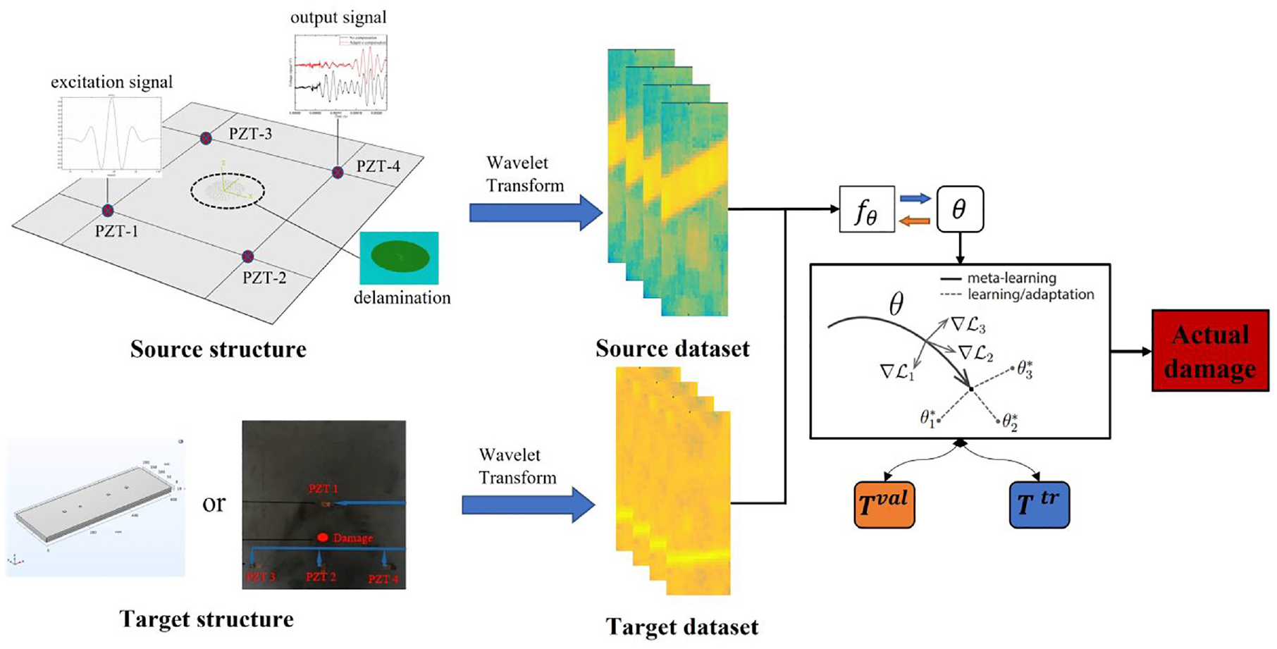
The workflow diagram of this article.
Deep CNN framework
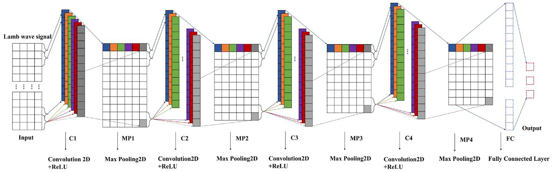
CNN, one of the most widely used deep neural networks, is specifically designed for processing and analyzing data with a grid structure. A classic CNN consists of convolutional, activation, and pooling layers and is commonly applied to process two-dimensional images and video data. 40 In this study, a 2D CNN is employed to extract damage features from images transformed by wavelets. Our CNN framework is built using Keras, as illustrated in Figure 2. Keras is a high-level neural network library written in Python. Its core idea is to facilitate rapid deployment and it can run on top of TensorFlow, CNTK, or Theano. It comprises an input layer, four 3×3 convolutional layers (C1, C2, C3, and C4), normalization layers (BN1, BN2, BN3, and BN4), max-pooling layers (MP1, MP2, MP3, and MP4), a fully connected layer (FC), and an output layer.
CNN framework.
After the sensors installed on the composite material structure collect the damage signals, wavelet transformation is performed to obtain image samples, which consist of multiple material layers of delamination damage. Convolutional layers use 64 filters to extract damage features from the input data. These filters are learnable parameters used to perform convolution operations on the input data to extract damage features. Subsequently, batch normalization is applied after the convolution operation to expedite the training process and enhance the ML model’s stability. Batch normalization helps ensure that the outputs of each module maintain a certain statistical distribution during training. Max-pooling layers are then used to reduce the size of the feature maps, minimizing computational overhead and extracting the most crucial damage features. The 2×2 max-pooling retains the maximum value within each 2×2 window, reducing the dimensions of the feature map by half, as illustrated in Figure 3.
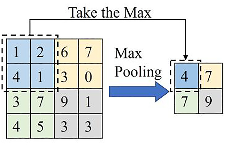
Max pooling.
After batch normalization, the rectified linear unit (ReLU) activation function is applied to introduce nonlinear properties. 41 ReLU sets negative values to zero while preserving positive values, aiding the network in learning complex damage features:
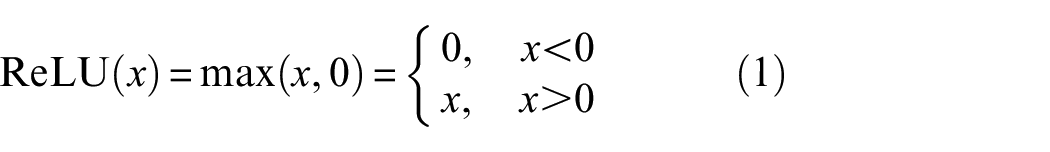
where x is the input.
Following the max pooling layer is the FC layer, where each neuron within it is connected to every neuron in the preceding layer, forming a FC structure. The preceding convolutional and pooling layers are utilized for extracting local damage features, while the FC layer combines these local damage features to form global damage features, used for the final classification or regression task. Finally, there is the output layer, with the number of neurons corresponding to the number of classes:
Soft function is employed for classification. 42
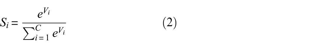
Here,
The loss function employs the cross-entropy cost function 43 :
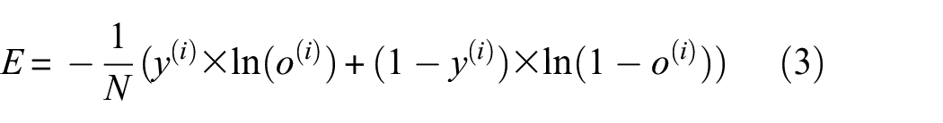
Here,
Deep TL strategy
As a deep learning technique, TL is widely applied to the issue of small-sample data, effectively enhancing the robustness of neural networks.44,45 TL can be categorized into optimization-based, model-based, and metric-based methods. 46 Among them, the optimization-based method has been extensively utilized and is employed in this work. The objective of this method is to minimize the loss across multiple learning tasks, enabling the TL model to quickly adapt to new tasks. Drawing upon the optimization-based learning concept, the CWTL ML model utilized in this study is designed by weighting the losses of different tasks in the outer training phase. The optimization process involves updating the CWTL ML model parameters through gradient descent. In the inner training phase, the CWTL ML model is adapted to tasks through several steps of gradient descent, while in the outer training phase, the CWTL ML model parameters are updated through gradient descent to minimize the overall loss of the learning tasks. The key idea is that through the learning process, the parameters learned by the CWTL ML model can better adapt to different tasks. This capability makes the CWTL ML model more amenable to TL, enabling rapid adjustment of CWTL ML model parameters with minimal samples when facing new tasks.
The optimization of inner training in CWTL involves the base learner, which randomly samples the
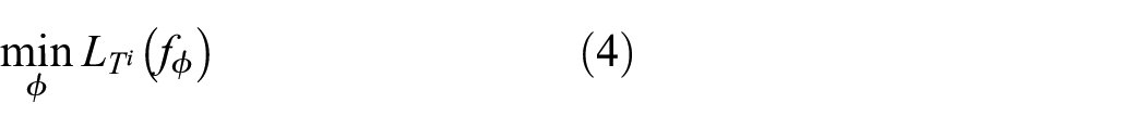
where
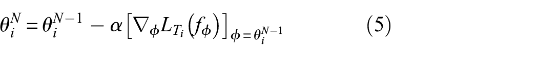
where
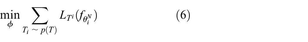
The meta-objective function is the sum of validation set losses across all tasks. The update of the meta-learner parameters is

The specific algorithm flow is as follows:
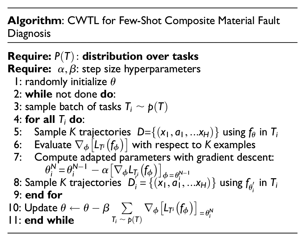
The CWTL involves two stages of gradient descent, one acting on the base learner and the other on the meta-learner. Figure 4 illustrates the update process of the specific task parameters
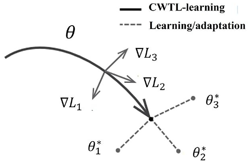
CWTL schematic diagram.
Experiments and simulations
Experiments setup
To verify the effectiveness and superiority of the proposed transfer learning-based fault diagnosis method for cross-workpiece fault recognition, experimental validation and data comparison were conducted using the damage data from composite material fault experiments by Professor Samuel da Silva’s team at the Department of Mechanical Engineering, São Paulo State University (UNESP/Ilha Solteira). The basic information of the structure is shown in Figure 5, which is referenced in da Silva’s paper.47,48 It consisted of 10 unidirectional layers, each laid in the 0° direction, forming a unidirectional laminate. The structure was equipped with four PZT sensors of the SMART Layer by Acellent Technologies Inc., with a diameter of 6.35 mm and a thickness of 0.25 mm. An excitation signal, a five-cycle burst signal with an amplitude of 35 V and a central frequency of 250 kHz, was applied to PZT 1. PZT 2, PZT 3, and PZT 4 were then used as the signal receivers, utilizing a sampling frequency of 5 MHz and a time duration of 200 μs. The actuator signal was generated by combining the NI USB 6353 from National Instruments (NIDaq) with the power amplifier EL 1225 from Mide QuickPack, and the output signal was collected using the oscilloscope DSO7034B from Keysight. The LabVIEW application controlled the generation/acquisition system. The damage was simulated by inserting industrial adhesive putty onto the surface panel. This additional local mass simulated the local variation in plate damping and was used to represent delamination damage in composites. Although this method did not fully capture the scattering effects or interactions with Lamb waves that might have occurred in actual delamination damage, it remained an effective representation of delamination damage for our study.49,50 The D5 level of delamination damage from the experiments was used to validate the CWTL ML model’s performance. Figure 5 illustrated the layout of the entire experimental setup.
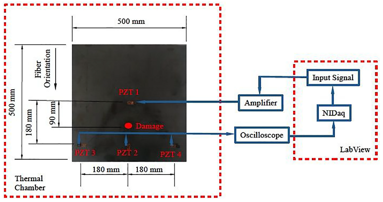
Experimental setup.
Simulations setup
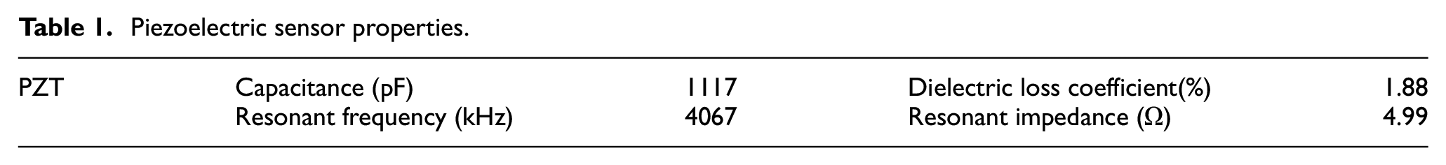
To verify the generalization ability of the designed CWTL ML model in workpieces with different geometric features, this study selected two representative workpiece numerical models for simulation: plate-type workpieces and cantilever beam workpieces. These two workpiece numerical models are widely used in practical engineering environments and exhibit significant differences in geometric features. The simulation software designated the plate as Workpiece 1 and the cantilever beam as Workpiece 2, as shown in Figure 6. The dimensions of the plate were 600*400*1.6 mm, and the dimensions of the cantilever beam were 600*200*2 mm. The PZT-5A (orthotropic) had dimensions of 2*2*1 mm. There were three rivet holes in the plate at the detection section, with delamination occurring at 150 mm along the positive x-axis direction of rivet hole 2. For the cantilever beam, delamination occurred at the coordinates (300,100). Four PZTs were placed on the plate, with the properties of the piezoelectric sensors outlined in Table 1. PZT-A was responsible for the excitation signal, while PZT-B, PZT-C, and PZT-D were responsible for signal reception. To ensure that the sensor positions did not impact the final monitoring results of the damage diagnosis system, PZT-A, PZT-B, PZT-C, and PZT-D were not arranged according to the internal force transmission paths within the plate and cantilever beam. Both the plate and the cantilever beam were composed of eight material layers laid along the thickness direction, with the layering sequence as
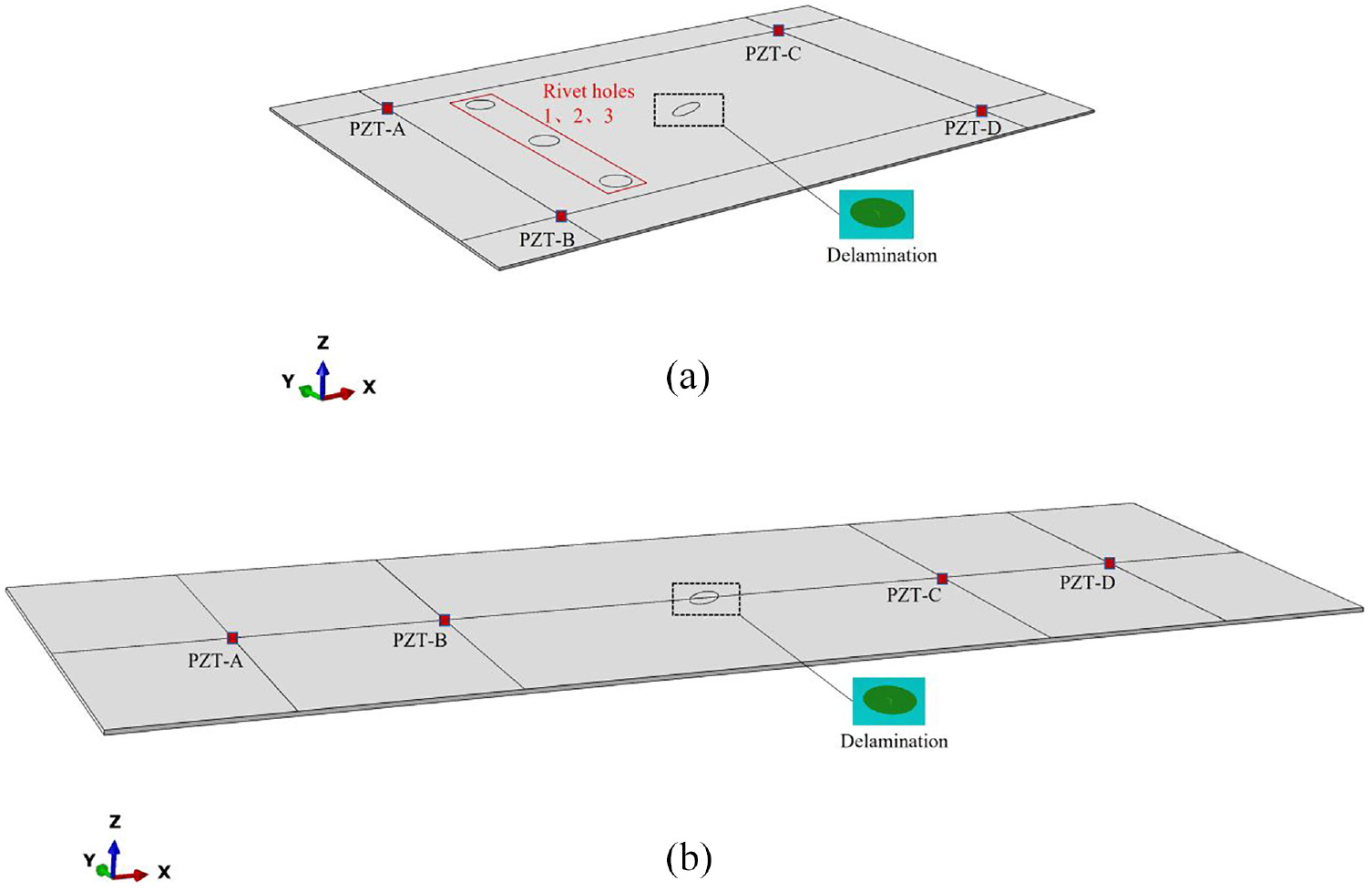
Plate (a) and cantilever beam 3D (b) generated in the simulation software: (a) plate 3D drawing and (b) overhanging beam 3D drawing.
Piezoelectric sensor properties.
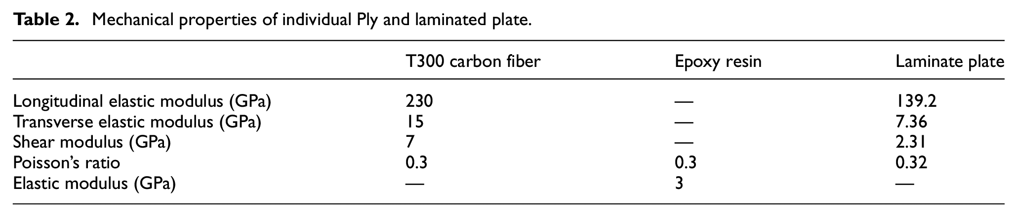
Mechanical properties of individual Ply and laminated plate.
The simulation selected the
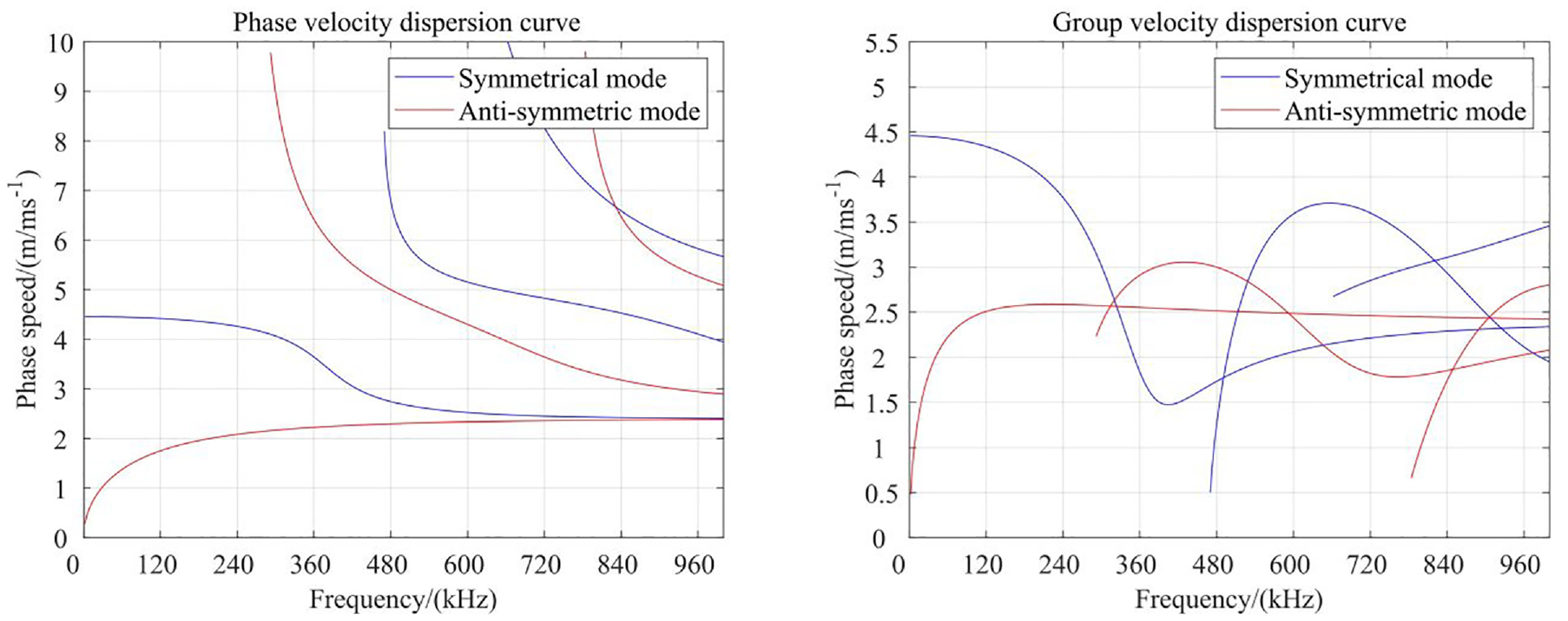
Lamb wave frequency dispersion plot.
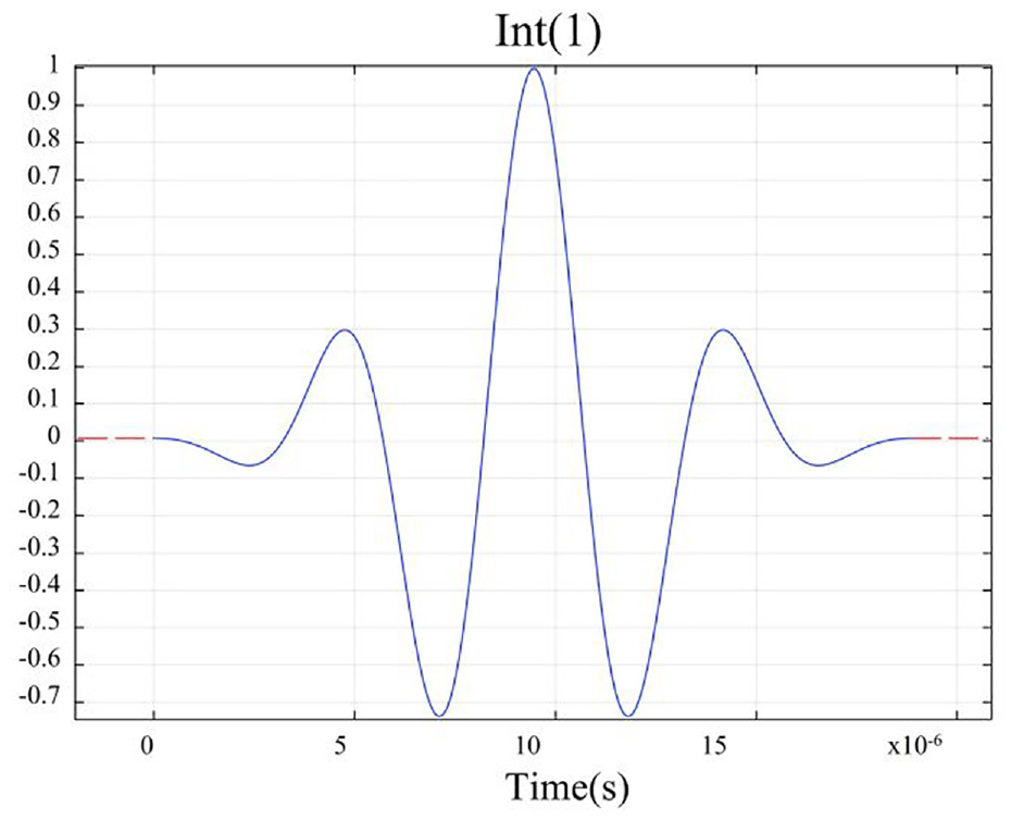
Excitation signal image.
To verify the CWTL ML model’s diagnostic capabilities for delamination under varying working conditions, delamination damage was separately introduced to the plate and cantilever beam, subjecting them to different temperature and loading effects. An elliptical representative delamination is modeled at the center of the composite plate. This delamination is located between two material layers of the composite plate. The simulation temperatures were set to 233.15, 263.15, 293.15, and 323.15 K, while a 200 N load was applied downward along the z-axis at the y-axis of the plate and cantilever beam.
Dataset setup
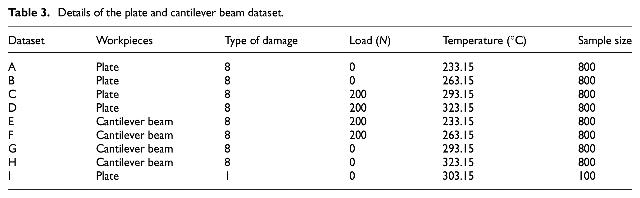
To ensure that Lamb waves carried more damage information and traveled a shorter time within the composite material, waveforms were collected from PZT-A to PZT-C in the plate and from PZT-A to PZT-B in the cantilever beam. The simulation demonstrated seven types of delamination damage: delamination between the first and second material layers, second and third material layers, and so forth up to the seventh and eighth material layers. Using MATLAB 2020b, damage signals in the time domain were transformed into time–frequency spectra via continuous wavelet transform. The time–frequency spectra were saved in JPG format, with a size of 224 × 224 pixels. Each type of damage was processed into 100 damage sample images after wavelet transform, and these were divided into training, validation, and test sets in a 7:2:1 ratio. The data obtained from the two workpieces under varying temperatures and loads formed a total of eight datasets, including seven types of damage and one healthy state. Additionally, the delamination signals of the first material layer in the CFRP workpiece fault experiment were selected to construct the dataset. Datasets A to H were generated through simulation, while Dataset I was generated experimentally. The detailed information on the datasets is presented in Table 3.
Details of the plate and cantilever beam dataset.
Preparation
Structural health monitoring strategy
According to the preparatory work before the experiments and simulations, the recommended structural health monitoring strategy directly utilized guided wave (time-history) data from the specified sensor network. These data were transformed into time–frequency scale map images by performing continuous wavelet transform. The Morse window function in MATLAB was taken into account, allowing control of the frequency and time resolution of the scale map by adjusting parameters such as symmetry and time-bandwidth product. These RGB scalar maps were then used as inputs for the machine-learning algorithm based on CWTL. In this study, the classification strategy based on CWTL was trained using time–frequency scale map images, conducting performance tests for the composite material structure’s delamination damage diagnosis method based on TL. Taking the example of the damage states between the first and second material layers (D12), the second and third material layers (D23), and the seventh and eighth material layers (D78), three data samples were randomly selected from the source domain. Figure 9 illustrates the time-domain signals of different delamination damages, while Figure 10 shows the corresponding time–frequency spectra.
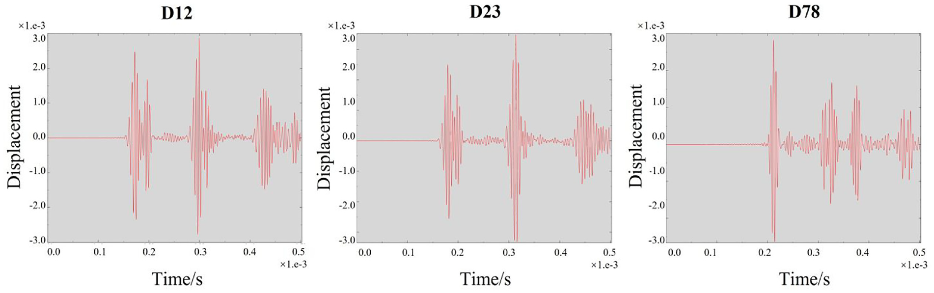
Time-domain signals for different damage states.
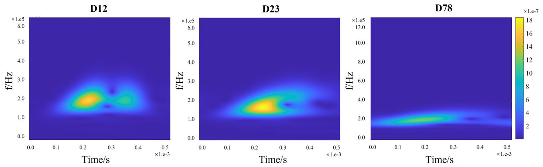
Time–frequency spectrum based on wavelet transform.
Networks parameter setup
In this article, both network training and algorithm testing were conducted based on the deep learning framework Keras. After the data preprocessing session, the size of the input image was set to 256 × 256. The initial value of the learning rate was set to 0.001, and the Adam optimizer was used. The number of iterations was set to 50, and the number of samples used in each training batch was set to 800. The damage diagnosis method proposed in this study was essentially a classification problem; therefore, the Softmax nonlinear classifier was used as the last layer of the neural network, and the cross-entropy cost function was used as the loss function. The above parameters were kept consistent for all the tests in the following section to facilitate the comparison of the diagnostic ability of different tests in terms of the damage level.
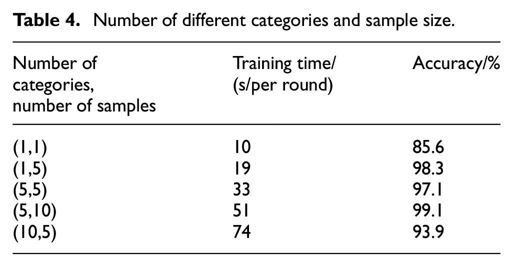
To ensure that the experiment closely aligned with real-world conditions and to reduce neural network training time, Dataset A was used as the source domain, and Dataset F as the target domain for classifying delamination damage. Different numbers of categories and sample quantities were selected for each trial. The number of categories referred to the quantity of delamination damage types from Dataset F used in each round, while the sample quantity referred to the number of images extracted from each damage type. Various combinations of categories and sample quantities were extracted for each round of testing. The evaluation metrics were based on the average training time and validation set accuracy for each round. The results are shown in Table 4. It was observed that as the number of categories decreased and the sample quantity increased, the average accuracy of the validation set improved. Considering the difficulty of collecting a sufficient amount of data for aircraft structures under actual conditions, a combination of five categories and five samples was selected for testing.
Number of different categories and sample size.
The proposed CWTL ML model was trained, validated, and tested using processed wavelet-transformed images as inputs. To achieve stable network performance, dataset A was utilized as the source domain, and dataset F + I was chosen as the target domain for 10 rounds of training, validation, and testing. Stage 1 involved selecting a classification task from the source domain dataset, followed by the computation of the loss function and the use of gradient descent to update the CWTL ML model parameters. Stage 2 entailed selecting a task from the dataset within the target domain, calculating the loss function, and evaluating the CWTL ML model performance using the updated parameters. Stage 3 involved aggregating the gradients of the loss function from the target domain dataset and using this gradient to update the initial parameters of the CWTL ML model. Stage 4 repeated the aforementioned steps, training the CWTL ML model to adapt to multiple different tasks. Figure 11 provides a training and validation result, illustrating the average process of validation accuracy and loss. Over the course of 50 epochs and 2500 iterations, the network did not exhibit any signs of overfitting. The validation accuracy took approximately 5–6 epochs to converge, as evidenced by the decreasing loss curve in Figure 11.
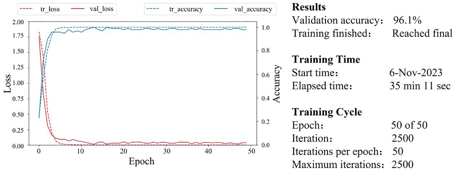
Transfer learning A → F + I process accuracy and loss curve.
Results
Comparative analysis of different fault diagnosis models
To verify the superiority of the CWTL machine learning model, the test selected five typical fault diagnosis ML models for comparative study, which was detailed as follows: 1. An integrated approach based on dimensionality reduction methods and deep belief networks (DBNs). The ML model decomposed the acquired vibration signals into single workpieces called intrinsic mode functions using ensemble empirical mode decomposition. It then tracked the instantaneous amplitude and frequency modulation signals of the single-workpieces amplitudes and combined comprehensive dimensionality reduction methods based on damage feature selection and damage feature extraction techniques to obtain a more sensitive low-dimensional damage feature set. 51 2. An optimized stacked denoising autoencoder was based on multidomain indicators. The ML model constructed multidomain indicators of the original vibration signal by computing expressions from different domains such as time–frequency domains. Subsequently, it used the constructed multidomain indicators as the input dataset, trained a stacked denoising autoencoder architecture with three hidden layers, and synchronously determined the ML model parameters of the stacked denoising autoencoder using a nature-inspired algorithm called Grasshopper Optimization Algorithm. 52 3. A multilayer gated recurrent unit (MGRU) method for gear fault diagnosis, where with an increase in the number of MGRU layers, damage features of different fault types could be identified more accurately. 53 4. A multiscale CNN (MSCNN) method, where the ML model extracted multiscale damage features simultaneously through a multibranch structure, acquires complementary and rich diagnostic information to extract the multiscale damage features contained in the vibration signal. 54 5. A deep learning model is based on Auxiliary Classifier GAN (ACGAN), where the deep learning model generated minority class samples to balance the dataset using a generator. With an improved discriminator, the deep learning model could simultaneously detect faults and classify them. 55
The recognition results of each method in the 16 cross-condition diagnostic tests are shown in Table 5 and Figure 12. Each result represented the average and standard deviation of 10 tests. It was observed that the designed CWTL consistently demonstrated the optimal diagnostic accuracy across all 16 cross-condition diagnostic tests. Among the applied methods, the diagnostic accuracy in the “Same temperature but different loads” tests were notably lower than that in the “Same load but different temperatures” tests. This indicated that, under a single linear interference scenario, external loads had a significantly higher impact on Lamb waves compared to temperature variations. In the tests involving both “Same temperature but different loads” and “Same load but different temperatures” variations, except for the Autoencoder (AE) and Recurrent Neural Network (RNN) methods, the remaining four methods maintained a diagnostic accuracy of over 90%. This suggested that most diagnostic methods could achieve high-precision damage identification for different types of damage under a single linear interference scenario. However, with the introduction of combined external load and temperature interferences, the diagnostic accuracy of the remaining methods exhibited varying degrees of decline. Specifically, the diagnostic accuracy of the DBN, CNN, and GAN methods dropped below 90%. In the “Mixing with CFRP layer failure experiments,” the decline for these methods was even more pronounced, indicating that several methods were no longer capable of completing the diagnostic task for delamination damage. This highlighted the limitations of existing deep learning models in cross-condition fault diagnosis problems. The proposed CWTL method maintained a diagnostic accuracy of over 95% even under multiple interfering factors. This demonstrated that the deep damage feature extraction module could learn more essential damage features under different working conditions, and the CWTL ML model designed based on optimization learning principles could accomplish the classification task of damage samples in small-sample scenarios. The test results indicated that deep damage feature embedding considering optimization learning exhibited stronger robustness and anti-interference capability in cross-condition fault diagnosis problems. Therefore, the proposed method demonstrated good generalization ability in addressing cross-condition fault diagnosis problems.
Diagnostic performance of different methods in 16 tests (%).
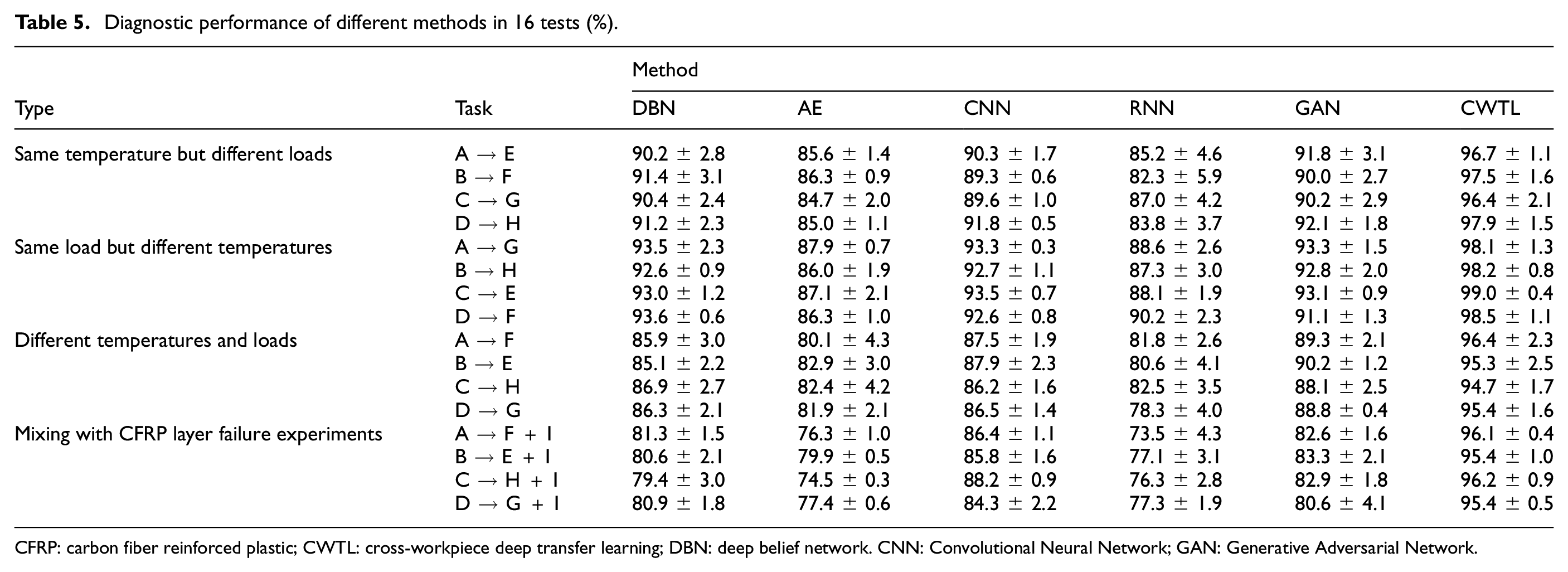
CFRP: carbon fiber reinforced plastic; CWTL: cross-workpiece deep transfer learning; DBN: deep belief network. CNN: Convolutional Neural Network; GAN: Generative Adversarial Network.
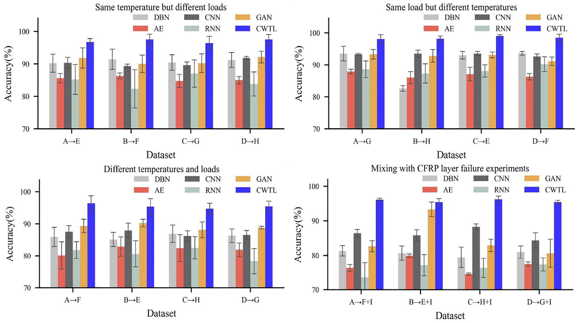
Diagnostic performance of different methods in 16 tests (%).
The validation of TL effectiveness
To intuitively explain the role of the CWTL method in cross-condition fault diagnosis scenarios, the accuracy of delamination damage detection in the target structure was evaluated. Four tests from the “Mixing with CFRP layer failure experiment” demonstrate damage feature distribution visualization using the t-distributed Stochastic Neighbor Embedding (t-SNE) method. It preserved the neighborhood structure of high-dimensional data in low-dimensional space for observing data distribution. In this study, the data were visualized in a two-dimensional space. Figure 13 displays the t-SNE results, where different colors represent different levels of damage in the workpieces, with D12 representing delamination between the first and second layers of composite materials, and so on. By incorporating optimization learning, CWTL effectively reduced the intra-class distance of the damage feature distribution for unknown operating conditions within a relatively small training sample size. It widened the interclass distance, demonstrating excellent performance in clustering similar training samples and segregating different class samples. Under the premise of no target operating condition data participating in ML model training, CWTL essentially achieved the expected objectives of the TL method. Fundamentally, within the embedded damage feature space of known operating condition training data, the reduction of intraclass distance and the expansion of interclass distance could effectively enhance the ML model’s damage feature discrimination capability, improve decision boundary generalization, and thereby mitigate the impact of operational variations on the mapping relationship of health status.
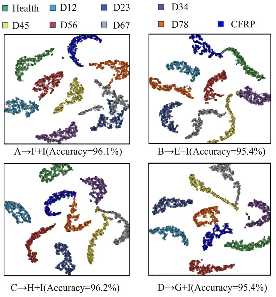
Visualization of the damage feature distribution.
The test results indicate that CWTL exhibits excellent classification accuracy. Furthermore, to quantitatively evaluate the classification performance of the designed CWTL, the following metrics were employed in this study: “True Positive Rate (TPR),”“False Positive Rate (FPR),”“True Negative Rate (TNR),” and “False Negative Rate (FNR).” The formulas for calculating these metrics are as follows:
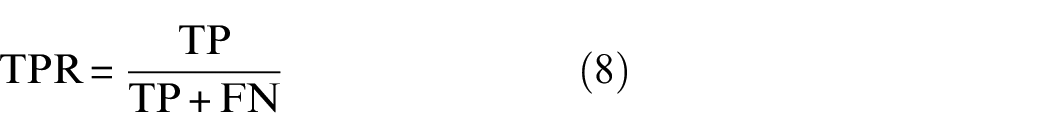
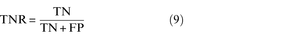
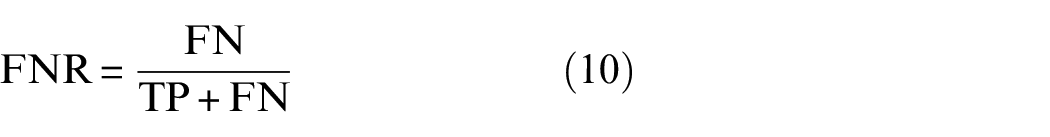
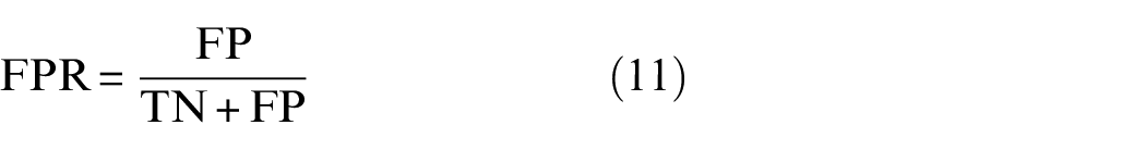
In this context, “True Positive (TP),”“False Positive (FP),”“True Negative (TN),” and “False Negative (FN)” refer to the correctness of the test results and the classification. These metrics help detect any bias in the classification results. TP represents the case where “the ML model correctly classifies positive samples as positive,” FP represents the case where “the ML model incorrectly classifies negative samples as positive,” TN represents the case where “the ML model correctly classifies negative samples as negative,” and FN represents the case where “the ML model incorrectly classifies positive samples as negative.” These metrics are crucial for assessing the performance of classification ML models and can be used to calculate additional performance indicators such as accuracy, recall, precision, and F1-score to quantify classification performance. Typically, the closer these additional metrics are to 1, the better the classification performance. These metrics are mathematically defined as follows:
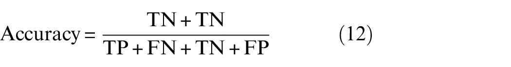
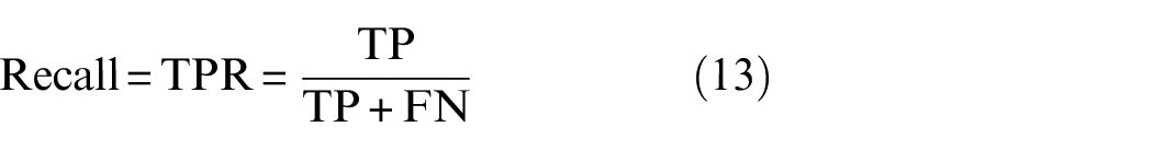
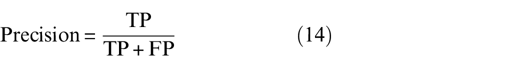
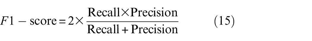
Table 6 lists the calculated results for all the above metrics for different data categories, where H represents the healthy condition, D12 represents delamination between the first and second layers of composite materials, and so on. Taking the A → F + I test as an example, since the accuracy, recall, precision, and F1-score. of the CWTL classification results were all close to 0.95, it can be concluded that the proposed method performed well for the classification of delamination damages under various operating conditions in composite material structures.
Evaluation metrics of CWTL’s classification performance on mixed datasets.
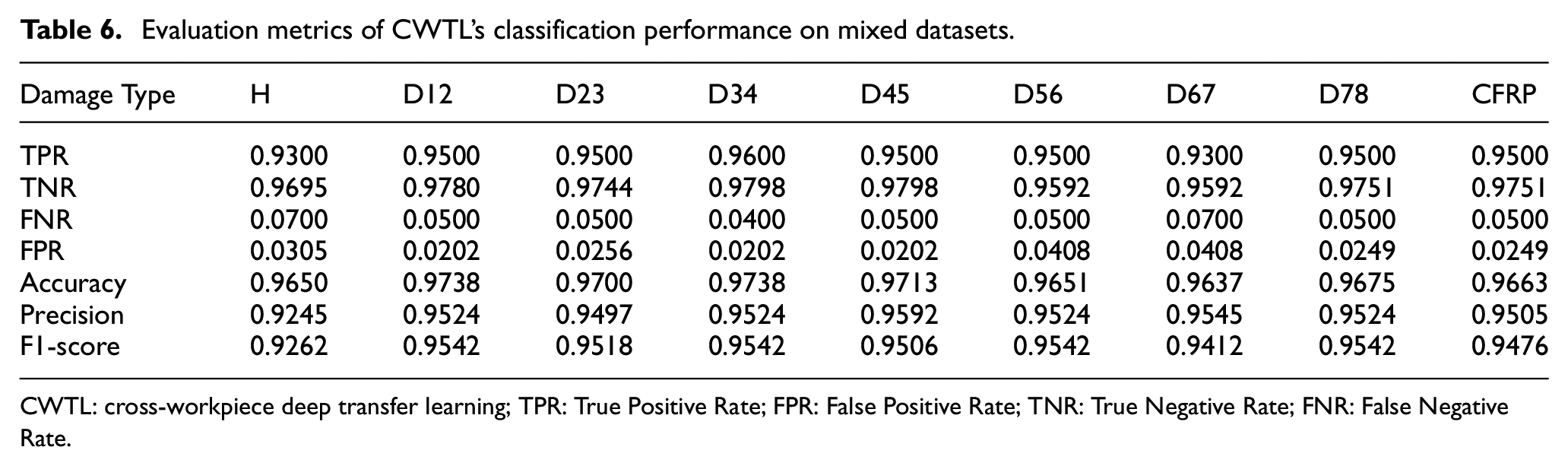
CWTL: cross-workpiece deep transfer learning; TPR: True Positive Rate; FPR: False Positive Rate; TNR: True Negative Rate; FNR: False Negative Rate.
Due to the specificity of delamination classification in small-sample data situations, and to achieve rapid adaptation of the ML model to the data in a small-sample scenario, further evidence was provided to demonstrate the superiority of the proposed method in this study. Confusion matrices were plotted for the CNN, GAN, and CWTL methods, which demonstrated better diagnostic results in test A → F + I, as shown in Figure 14. The labels on the horizontal axis represented the predicted delamination damages by the ML models, while the vertical axis represented the actual damage states. Comparing the three classification confusion matrices in Figure 14, it was observed that the proposed method performed well in the fault diagnosis of composite material delamination. The CNN method had an overall accuracy of 86.2%, the GAN method had 82.3%, while the CWTL method exhibited a significant performance improvement, with an overall accuracy of 95.8%. In conclusion, the proposed transfer learning-based aircraft structural damage diagnosis method demonstrated excellent damage feature extraction capabilities for damage Lamb wave signals. It was able to accomplish the TL damage diagnosis task for variable working conditions and different workpieces in a small sample scenario.
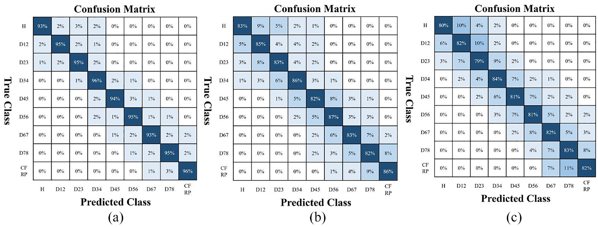
Comparison of confusion matrix results for three ML models: (a) CWTL, (b) CNN, and (c) GAN.
Conclusion
This study proposed a transfer learning-based diagnostic approach for delamination damage detection in composite materials, targeting the delamination localization of damage sources within composite structures. The effectiveness of the proposed method was demonstrated by accurately characterizing the depth position of damage sources within the target composite components. Furthermore, this structural health monitoring approach eliminated the need for extensive annotated damage data, relying instead on a minimal amount of unlabeled damage data to evaluate delamination damage in composite structures. The key contributions were outlined as follows:
The method enabled the assessment of the structural health of in-service composite materials based on a limited number of damage samples. Serving as an extension of the author’s prior work on damage detection, it facilitated delamination detection during the progressive stages of composite delamination. Compared to five mainstream ML-based damage detection methods, the proposed CWTL machine learning model demonstrated superior detection performance for delamination damage in composite materials under varying operational and component conditions.
A CNN model was designed for the extraction of specific acoustic features from Lamb wave monitoring data collected from composite components to aid in the characterization of composite damage features. The ML model’s loss function in the deep damage feature space was optimized, identifying a suitable initial parameter range with minimal data, altering the direction of gradient descent to find initial parameters that were more sensitive to the task. This enabled the ML model to quickly fit with limited datasets and effectively enhance its identification accuracy in cross-condition fault diagnosis tasks.
The study investigated the influence of different source data on learning performance. It was observed that transferring from the same external damage conditions significantly impacted the ML model’s learning performance, surpassing the TL tasks with different external temperature and load conditions.
In addition to the aforementioned contributions, based on the findings of this research, some further improvements can be made in future work. In actual in-service conditions, the damage in composite components often exhibits multiple types of damage coupling, with complex Lamb wave propagation mechanisms and intricate mapping mechanisms between external load forms and wave responses. The current research is inadequate in addressing the identification of multitype damage coupling under working load states, resulting in poor accuracy and low credibility in the identification of unknown damages in complex service environments for composite structural components. Therefore, future work will focus on proposing fault diagnosis methods tailored to multitype damage coupling.
Footnotes
Declaration of conflicting interests
The author(s) declared no potential conflicts of interest with respect to the research, authorship, and/or publication of this article.
Funding
The author(s) received no financial support for the research, authorship, and/or publication of this article.