
Abstract
Magnetic pumps transmit torque without leaks using magnetic induction, offering superior sealing over conventional pumps by replacing dynamic with static seals. They are vital for handling hazardous or valuable fluids, enhancing safety and efficiency while cutting maintenance costs. Despite their reliability, they face failure risks from temperature, lubrication, and contamination. This article reviews fault patterns, causes, and impacts in magnetic pumps and explores advanced sensor-based and intelligent diagnostic methods to predict and prevent failures, ensuring stable operation and reducing downtime. It provides a comprehensive overview of current fault diagnosis techniques and future research directions in the field.
Introduction
Magnetic pumps, known for their leak-proof design, significantly enhance the safety of industrial processes when conveying flammable, explosive, toxic, or corrosive media by reducing the risks of environmental pollution, fires, and explosions associated with the leakage. Magnetic pumps operate on the principle of magnetic induction to transmit torque and replace dynamic seals with static ones. The conveyed medium in pumps is encapsulated by an isolation sleeve. The seal-less design eliminates frequent seal replacements and reduces efficiency losses and failures due to sealing friction. The lifecycle maintenance costs are reduced by 20–30% compared to traditional pumps. The advancement of high-performance permanent magnet materials has increased the transfer efficiency and broadened the application range of magnetic pumps. With the global demand for sustainable and environmentally friendly technologies on the rise, the market demand for magnetic pumps is expected to grow at an annual rate of 5–10%. 1
The development of magnetic drive pumps originated in the 1940s when British brothers Charles and Geoffrey Howard invented magnetic drive pumps to tackle leakage in hazardous media transport. Subsequently, the German Bayer Chemical Company and the UK’s Imperial Chemical Industries adopted these pumps, marking a new chapter in their development. The initial transmission efficiency of magnetic couplings was constrained by the performance of permanent magnets. However, the 1980s saw a breakthrough in high-performance neodymium iron boron (NdFeB) magnets for magnetic pump technology development. Sundyne Corporation, a global leader in magnetic pump R&D and production, expanded its capabilities for diverse demands by acquiring UK HMD, American ANSIMAG, and Italian CASTER. China’s magnetic pump technology development began later in the late 1970s to early 1980s, primarily in major research institutions. Since the 1980s, China has focused on independent development, with the Gansu Provincial Academy of Sciences’ Magnetic Device Research Institute and Taicang Magnetic Pump Co., Ltd. successfully developing internationally advanced magnetic drive centrifugal pumps, showcasing China’s technological maturity and innovation capabilities. 2
Magnetic pumps can face demagnetization of key components such as couplings due to temperature increases, wear in sliding bearings from inadequate lubrication or contamination, and damage to isolation sleeves from eddy current losses in Alternating Current (AC) magnetic fields. Cavitation in internal flows can also intensify pump vibration and noise. Motor may fail due to overload or material fatigue. Advances in sensor technology, data processing, and intelligent algorithms all enhance the development of fault diagnosis techniques, which can help predict and alert potential issues during magnetic pump operation. In the era of Industry 4.0, global industrialization accelerates and leads to a growing need for the reliability, efficiency, and longevity of industrial systems, which has intensified the focus on machine learning (ML) techniques applied in prognostics and health management (PHM) as summarized by Su and Lee. 3 Moreover, they proposed a unified framework for applying ML techniques to guide the development of future PHM models, offering valuable insights and guidance.
Obviously, the production efficiency and economic benefits can be enhanced to ensure the stable and reliable operation of magnetic pumps at optimal conditions. However, there is currently a lack of comprehensive review papers specializing in magnetic pump fault diagnosis techniques for reference. This article will provide a review of two aspects based on existing research:
Various faults are categorized according to different contributing components of the magnetic pump, followed by the illustration of the causes and impacts of each fault with numerous real cases and schematic analysis.
Common fault diagnosis techniques for magnetic pumps are introduced with specific analysis of data analysis and fault identification methods. The developmental level of fault diagnosis techniques is summarized. In addition, the latest fault diagnosis methods applied to conventional centrifugal pumps are reviewed to compensate for the current deficiencies in magnetic pump fault diagnosis research.
The remainder of this review paper is organized as follows. “The structure and working principle of magnetic pumps” section introduces the structure and working principles of magnetic pumps. “Causes and impacts of common failures in main components of magnetic pumps” section summarizes the modes of magnetic pump faults and discusses the causes and impacts of faults. “Fault diagnosis technologies” section provides a detailed review of existing and potential fault diagnosis methods for magnetic pumps. Finally, conclusive comments and research prospects are given in “Conclusions and outlooks” section.
The structure and working principleof magnetic pumps
The key components of magnetic pumps are shown in Figure 1. The heart of the magnetic pump is the magnetic coupling, which consists of inner and outer magnetic rotors as well as an isolation sleeve. The synchronous rotation is achieved through the action of the magnetic field without physical contact, thereby eliminating traditional shaft sealing issues and ensuring leak-free medium transfer.
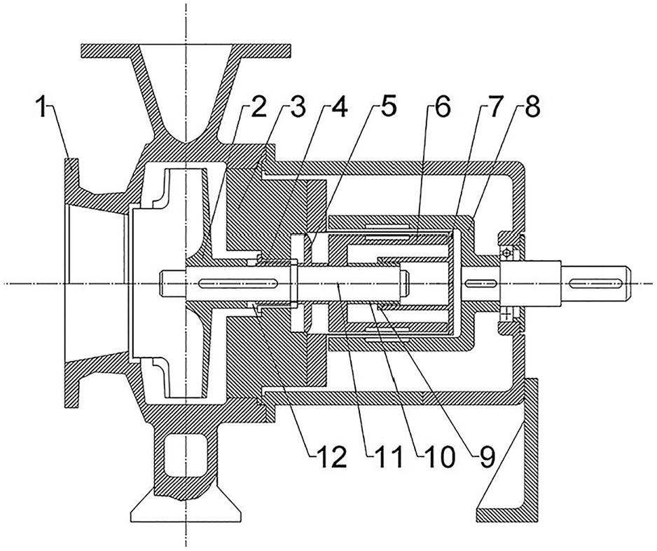
Schematic diagram of magnetic pump structure. 1—Pump body; 2—impeller; 3—pump casing; 4—front bushing; 5—balance disk; 6—inner magnetic rotor; 7—isolation sleeve; 8—outer magnetic rotor; 9—sliding bearing; 10—rear bushing; 11—pump shaft; 12—thrust ring.
Magnetic couplings are categorized into two structural forms, which are cylindrical and disk-shaped. Under identical magnetic circuit conditions, the cylindrical magnetic coupling is widely used due to its larger torque transmission capacity. 4 Such coupling is composed of inner and outer magnetic rotors, a driving and driven shaft, and an isolation sleeve. The magnetic blocks are radially magnetized, creating an alternating polarity arrangement of N–S and S–N. During the operation of the magnetic pump, the differential rotation angle between the inner and outer magnetic blocks generates a circumferential push-pull force and then transmits torque. The isolation sleeve seals between the inner and outer magnetic rotors to prevent medium leakage while withstanding loads caused by medium pressure and vibration. The material selection for the isolation sleeve is crucial to its performance. Metallic isolation sleeves are widely used due to their mature technology. But they also generate eddy current losses in the alternating magnetic field, leading to temperature rise and degrading the efficiency of the magnetic coupling. 5 To address this issue, a cooling circuit has been designed to guide partial medium through the circuit. Then the heat generated by eddy current and friction losses is removed to reduce the operating temperature of the magnetic pump. Nonetheless, the loss of cooling flow still reduces the pump efficiency to some degree. 6
During operation, radial and axial forces generated by unsteady flow act on various components of the magnetic pump, potentially causing pressure pulsations, vibrations, and noise. 7 Under low flow conditions, the complex recirculation and diversion lead to higher radial and axial forces. 8 These forces gradually decrease as the flow rate increases. Balance holes, back vanes, and balance disks are designed to counteract these forces. Particularly, balance holes are extensively used in centrifugal pumps and come in two forms which are one on the impeller and the other on the inner shaft. The latter requires higher machining precision. Kim and Yun 9 conducted research on the internal flow characteristics and found that the design of balance holes on the inner shaft is more suitable for magnetic pumps. Moreover, such a design effectively balances axial and radial forces and enhances pump performance and reliability.
Causes and impacts of common failures in main components of magnetic pumps
Magnetic couplings
(1) Structure and transmission principle
Magnetic couplings, also known as magnetic clutches, transmit torque generated by the motor without contact on the basis of the principle of magnetic induction. Compared to traditional mechanical couplings, the advantage of magnetic couplings is the replacement of dynamic seals with static seals, thereby significantly enhancing the reliability of the seal. Magnetic couplings come in two structural forms, which are cylindrical and disk-shaped. Under identical magnetic circuit parameters, cylindrical magnetic couplings can achieve greater torque transmission within a unit magnetic volume because of the high utilization rate of magnetic steel. 10 Disk-shaped magnetic couplings generate significant axial forces between the magnetic steels, necessitating additional measures to balance these forces and prevent fatigue damage to the isolation sleeve under alternating loads. Therefore, to pursue higher transmission efficiency, cylindrical magnetic couplings are more commonly used.
The cylindrical magnetic coupling shown in Figure 2 is composed of three main parts, which are the inner magnetic rotor, the outer magnetic rotor, and the isolation sleeve. Both the inner and outer magnetic rotors are made from magnetized steel, with 8–28 permanent magnets installed in parallel along the axial direction on their cylindrical surfaces. These magnets are typically made from high-performance materials such as neodymium iron boron (NdFeB) or rare earth cobalt (SmCo). The contactless design of the magnetic coupling can effectively prevent mechanical damage caused by overload. The transmission efficiency may be slightly lower than that of traditional mechanical couplings due to reliance on magnetic force for torque transmission. The arrangement of the permanent magnets significantly affects the efficiency of torque transmission. The Halbach array is particularly esteemed for its high transmission efficiency, allowing for greater torque under the same magnetic circuit parameters.11,12 The motor-driving shaft is connected to the outer magnetic rotor and the pump-driven shaft is connected to the inner magnetic rotor. The motor drives the rotation of the outer magnetic rotor, which in turn transmits torque to the inner magnetic rotor through the magnetic field, and then drives the rotation of the pump shaft. The design of the isolation sleeve is crucial since not only isolating the inner and outer magnetic rotors but also sealing the conveyed medium to ensure leak-free performance during the transmission process. The isolation sleeve comes in three forms: metallic, nonmetallic, and composite. The inner magnetic rotor and the conveyed medium are sealed to prevent any seepage, emission, dripping, or leakage during the transmission process.
(2) Causes and impacts of magnetic coupling faults
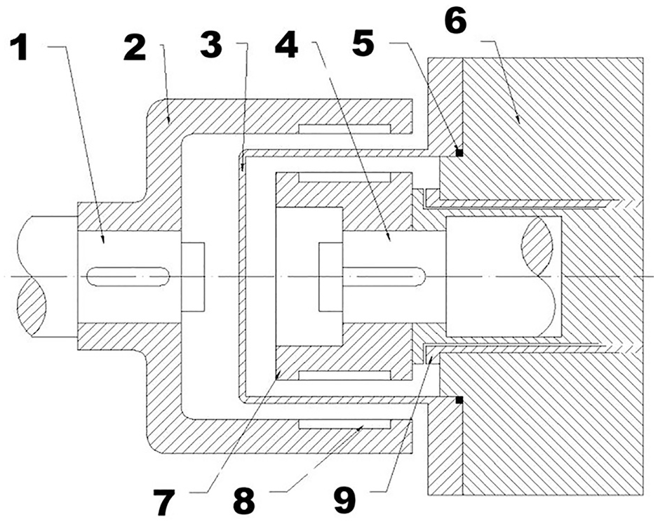
Scheme of cylindrical magnetic coupling structure. 1—Motor shaft; 2—outer magnetic rotor; 3—isolation sleeve; 4—pump shaft; 5—seal ring; 6—pump housing; 7—inner magnetic rotor; 8—permanent magnet; 9—sliding bearing.
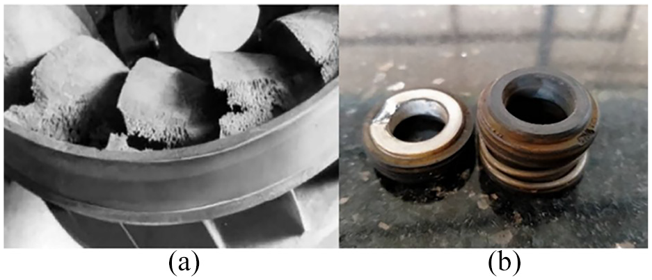
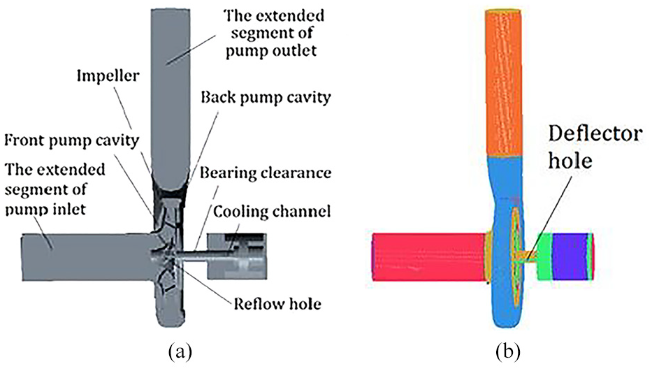
Figure 3 illustrates the failure of the magnetic coupling, which primarily stems from the demagnetization of permanent materials. This demagnetization effect directly impacts the efficiency of torque transmission, thereby reducing the overall performance of the magnetic pump. In extreme cases, if the permanent magnets completely lose their magnetism, the magnetic pump will be unable to operate normally. The decline in magnetism of permanent magnets is influenced by various factors, including operating environment, external magnetic fields, and temperature. Especially, temperature has a particularly significant impact. The temperature rise in the magnetic coupling during operation is mainly due to eddy current losses. 13 When the magnetic coupling works, the inner and outer magnetic rotors transmit torque through magnetic induction. The isolation sleeve situated in the alternating magnetic field cuts the magnetic flux lines and then generates the current that forms a closed circuit known as an eddy current. These eddy currents convert energy into thermal energy and cause further temperature increases in the magnetic coupling. 14 Commonly used permanent magnet materials, such as neodymium iron boron and samarium cobalt, weaken as the temperature rises and lose their magnetism once the temperature exceeds the Curie temperature, which leads to failure in the magnetic coupling. Gao et al. 15 conducted a numerical simulation analysis of the flow-heat coupling in the cooling circuit of the magnetic pump to reveal the convective heat transfer and temperature distribution within the cooling circuit. A detailed analysis of the temperature and pressure distribution was conducted for the gap, bottom, and return hole areas in the isolation sleeve. Experimental validation confirmed the accuracy of the simulation results, which showed the highest temperature at the bottom of the isolation sleeve and higher pressure and temperature at the inlet of the return hole, with lower pressure at the outlet. The study indicated that under different operating conditions, the convective heat transfer coefficient of the isolation sleeve is relatively lower than that of the magnetic coupling.
Magnetic coupling faults: (a) permanent magnet bulging and (b) inner magnetic steel worn through. 16
Magnetic pump sliding bearings and isolation sleeves
(1) Design principles and operational characteristics
Due to the unique design requirements and operating environments, magnetic pumps commonly utilize sliding bearings instead of the rolling bearings typically found in centrifugal pumps. Magnetic pumps demand superior sealing performance since specifically engineered to convey potentially hazardous or high-value liquids. Sliding bearings can effectively prevent medium leakage and ensure the safety and reliability of the pump because of their excellent sealing capabilities. Such bearings are capable of withstanding significant radial and axial loads with a relatively simple structure that reduces the complexity of the pump body and conserves internal space, allowing for a more compact design compared to traditional pumps. Table 1 outlines the differences between the sliding bearings in magnetic pumps and the rolling bearings in centrifugal pumps. The sliding bearings of a magnetic pump, in conjunction with the internal isolation sleeve, inner magnetic rotor, and pump chamber, form a sealed system that guarantees the tightness of the conveyed liquid. So the possibility of leakage is essentially eliminated. Due to sealing, the lubrication of magnetic pumps primarily relies on the conveyed medium. 17
Differences between the sliding bearings in magnetic pumps and the rolling bearings in centrifugal pumps.
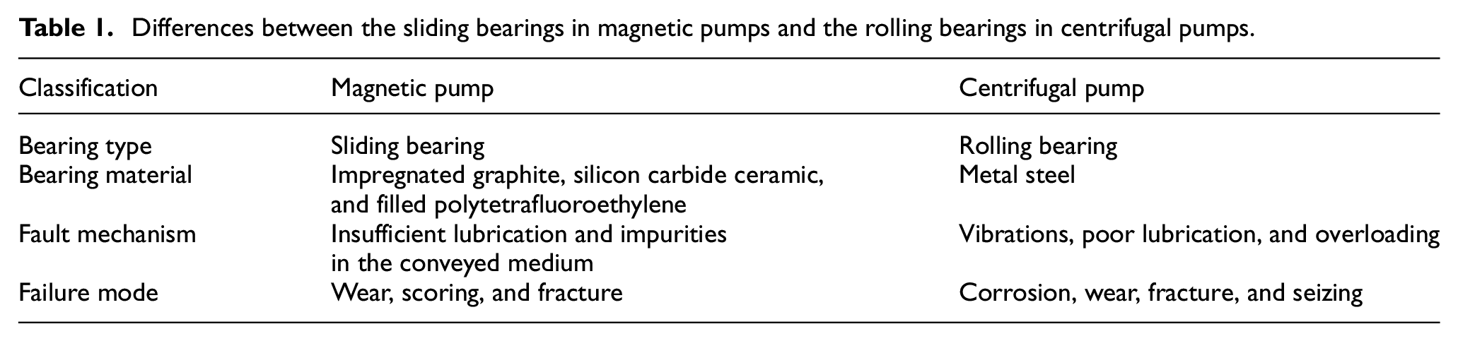
Considering the potential to convey corrosive or high-temperature chemical liquids, the material selection for sliding bearings in magnetic pumps is crucial. Materials including impregnated graphite, silicon carbide ceramic, and filled polytetrafluoroethylene are commonly chosen, which offer not only excellent wear resistance and corrosion resistance but also the capacity to withstand high temperatures. However, despite the performance advantages of these nonmetal materials, their mechanical strength is typically lower than that of metals. In addition, their ability to resist vibration is comparatively poor. Therefore, when designing the sliding bearings for magnetic pumps, it is necessary to consider both the physical properties and mechanical strength of the materials to ensure that the bearings meet the requirements for lubrication and sealing meanwhile also withstanding the loads and challenges during operation.
The isolation sleeve of a magnetic pump is a critical component that ensures leak-free performance. The material selection for this part is essential. Generally, the material must have excellent mechanical properties of high strength and good toughness to withstand fluid pressure, impact, and vibration with a relatively thin wall. There are three types of isolation sleeves which are metallic, nonmetallic, and composite. Metallic sleeves are made from materials that are nonmagnetic and highly electrically resistant, offering good rigidity and hardness while suffering from higher eddy current losses due to their good conductivity. Nonmetallic sleeves often use fluoroplastic or carbon fiber plastic which have lower eddy current losses but are relatively less rigid and hard, making them more susceptible to fatigue and damage. Composite sleeves combine a plastic outer wall with a metallic lining to balance rigidity, hardness, and eddy current losses. The thickness of the isolation sleeve typically ranges from 1 to 2 mm.
(2) Causes and impacts of sliding bearing faults
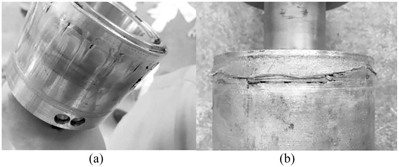
The sliding bearings of magnetic pumps rely on the lubricity of the conveyed medium. However, wear or damage to the bearings is inevitable since the medium is insufficiently lubricated or contains impurities and particles. The bearing load is limited to the design. The failures occur once the internal and external forces exceed load limits during operation. For instance, excessive imbalances in radial and axial forces generated during the operation can accelerate bearing wear. Overloading is also a common cause of bearing failure. Pressure pulsations in the pump cooling circuit can induce the alternating load, which may lead to failure when applied to the sliding bearings. Excessive axial and radial forces likewise accelerate wear and shorten the service life of bearings. 18 Burger et al. 19 found that in the petrochemical field sliding bearings seized up to nine times in a year, leading to severe consequences. The manifestations of failure are shown in Figure 4, including (a) brittle fracture of the shaft sleeve, (b) and (c) seizure between the bearing and the shaft sleeve, and (d) severe scoring on the bearing surface and significant damage to the active thrust ring. In extreme cases, sliding bearings with insufficient material hardness may even fracture directly.
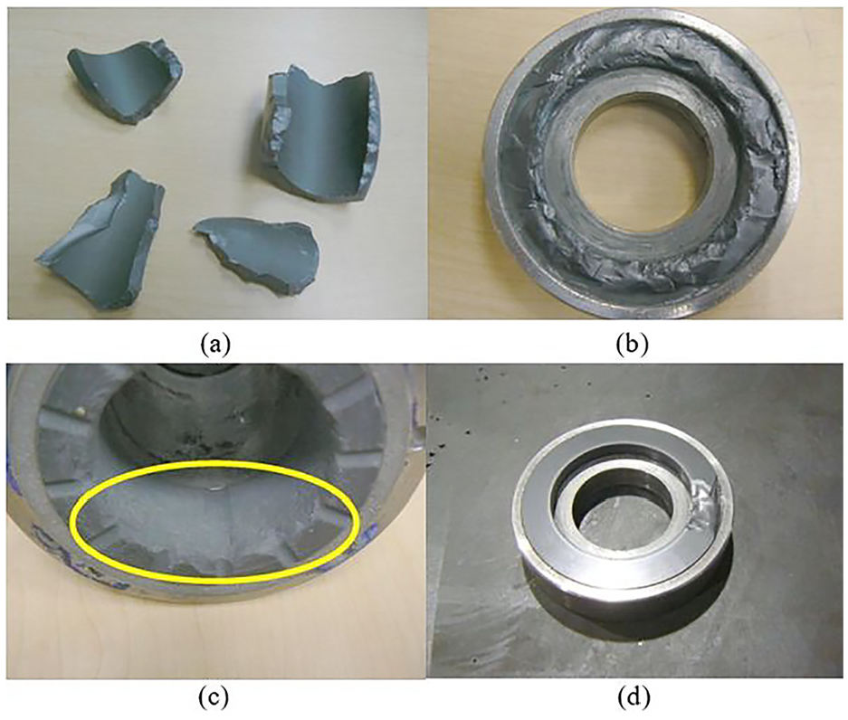
Sliding bearing faults: (a) brittle fracture of the shaft sleeve, (b) and (c) seizure between the bearing and the shaft sleeve, and (d) severe scoring on the bearing surface. 19
The aforementioned research indicates that pump failures may stem from tribology issues. Comparative analysis between failed and normal pumps revealed that the failed pump had an inadequate lubrication film thickness, potentially influenced by radial clearance of bearings, medium viscosity, and specific radial load on bearings. Evidently, the root cause of magnetic pump failures is the inability to form a sufficiently thick hydrodynamic lubrication film on the bearings. If cavitation occurs, the entrained vapor bubbles flowing through the sliding bearings can disrupt the lubrication film on the bearing surface, which exacerbates wear and increases temperature. To monitor the wear of magnetic pump bearings, Pei et al. 20 have designed an innovative sensor to transform curved surface measurements into planar ones. Meanwhile, the sensor incorporates magnetic conductors, magnetic steel, and linear Hall integrated circuits to enhance linearity and stability. Experimental validation has confirmed that the sensor can effectively detect radial and axial displacements of the magnetic pump shaft.
(3) Causes and impacts of isolation sleeve faults
The wear of the isolation sleeve depicted in Figure 5 is typically caused by increased temperature and friction. When bearing wear increases radial clearance and the rotor deviates from its geometric center, uneven gaps between the inner and outer magnetic rotors can intensify the magnetic attraction. Consequently, the potential friction between the inner magnetic rotor and the isolation sleeve results in temperature rise and sleeve damage. The increased power of the magnetic pump leads to increased eddy current losses, which are ultimately dissipated as thermal energy and increase the temperature of the isolation sleeve. During the startup phase, dry running may generate a significant amount of heat due to friction and cause the temperature of the magnetic pump to rise. Gao et al. 21 utilized Computational Fluid Dynamics (CFX) software for numerical simulation of the cooling circuit of the magnetic pump to reveal the development patterns of pressure pulsations and their impact on external characteristics. Gao analyzed the pressure pulsations of the main flow components and found that these pulsations can cause damage to the isolation sleeve and bearings. Zhang et al. 22 found that the blade outlet angle has a significant impact on the radial force of the magnetic pump. They compared models with different blade outlet angles (25°, 30°, 35°, and 40°) and found that with the same blade outlet angle, the radial force decreases gradually with increasing flow rate. Conversely, under the same flow rate, an increase in the blade outlet angle leads to the inclination of the radial force. Vibration test results further confirmed the influences of the blade outlet angle on the radial force and vibration of the magnetic pump unit.

The wear of the isolation sleeve. 16
Causes and impacts of pump faults
Pump failures can occur independently or be interrelated, potentially triggering a cascade of reactions. Thus, evaluating the combined impacts of failures is crucial. 23 The academic community has conducted extensive research on common faults within pumps, as depicted in Figure 6, including cavitation, impeller wear, suction blockage, and seal damage. For instance, Tian et al. 24 diagnosed static and dynamic torque changes caused by pump impeller faults and cavitation by analyzing motor current signals. Kumar et al. 25 identified blockages in the suction pipe of pumps using a combination of multi-sensor data. Yu and Liu 26 analyzed the loosening of the pump impeller underrated conditions and noted that it was caused by the degradation of the material microstructure. The authors 27 proposed a new Hilbert–Huang transform (HHT)-based indicator for cavitation evolutionary detection in pumps by motor current signal analysis. Moreover, in the authors’ previous work, the nonlinear characteristics of pump vibration signals were analyzed using a cyclic stationary spectrum, achieving the identification of cavitation and mechanical seal failure states in centrifugal pumps. 28
Magnetic pumps differ structurally from centrifugal pumps, leading to distinct causes and impacts of failures. The medium within a magnetic pump serves as the lubricant, which is easy to heat and triggers cavitation compared to conventional centrifugal pumps. During cavitation vapor bubbles in the medium transported by the magnetic pump can rapidly collapse and burst in high-pressure areas, so that the flow components are damaged. Moreover, the implosion of vapor bubbles intensifies the pump vibration, noise, and pressure fluctuations then reduces its performance. Moreover, the nonuniform impact on the impeller surface may lead to blade wear and corrosion. 30 To address issues caused by cavitation, magnetic pumps are designed to be equipped with internal cooling circuits to dissipate heat generated by eddy currents. However, if vapor bubbles enter the internal circulation cooling circuit, it may damage the flow-passing components and affect the cooling efficiency. Based on numerical simulation studies, Kong and Shen 31 found that the pressure near the volute tongue is significantly high, which is a primary reason for cavitation in high-speed magnetic pumps. It is particularly important to note that the return hole of the cooling circuit located in the impeller low-pressure area is susceptible to cavitation, 6 which requires attention in both design and maintenance.
Causes and impacts of motor faults
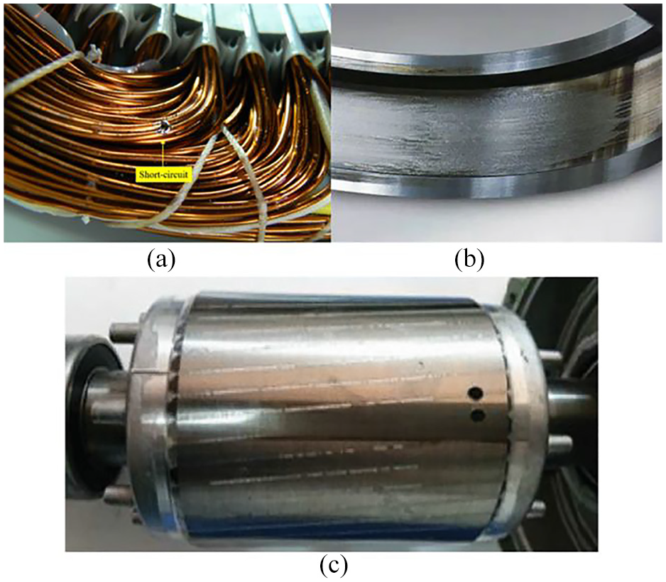
The driving motor of a magnetic pump is typically a standard three-phase asynchronous motor, which is composed of critical parts such as the stator, rotor, shaft, and bearing. When three-phase alternating current passes through the stator windings, it generates a rotating magnetic field on the rotor and drives the rotor to rotate in turn. However, due to a speed difference, the rotation is asynchronous. The motor rotor is directly connected to the outer magnetic rotor of the magnetic coupling, which then drives the inner magnetic rotor and enables the pump operation. As shown in Figure 7, common failures of the driving motor in magnetic pumps are broadly categorized into three types, which are stator faults, bearing faults, and rotor faults. 32
(1) Stator faults
The stator is a crucial stationary component in an electric motor, which is composed of windings, a laminated core, and a frame. The stator core is typically constructed from multiple layers of silicon steel sheets to reduce eddy current losses and enhance torque transmission. The windings are meticulously crafted from insulated copper or aluminum wires to prevent current leakage. The stator windings must have excellent insulating properties. Stator failures are extremely common in asynchronous motors accounting for 30–40% of all malfunctions, which often initiate with inter-turn short circuits in the stator windings. 35 The degradation of insulating materials caused by overheating, electrical overload, discharge, or mechanical stress at the ends of the windings is the primary cause of short circuits. 36 Once an inter-turn short circuit occurs, the high current in the failed coil may lead to the spreading fault and chain reaction. The initial inter-turn short circuits may have minimal impact on motor operation if not detected and addressed in time. The fault could propagate throughout the entire stator core and windings, potentially leading to the complete failure of the motor. 33
To investigate the fault mechanism of stator inter-turn short circuits, researchers have proposed a variety of methods. Nakamura et al. 33 introduced a deep Deep Learning (DL)-based approach that analyzes the rotational sounds of faulty and healthy motors during no-load tests, using long short-term memory (LSTM) 37 networks to analyze minor faults characteristics in bearings or stator windings. Irhoumah et al. 38 developed a statistical method for analyzing stator inter-turn short circuit faults by measuring data from the external magnetic field and calculating the Pearson correlation coefficient. Sunal et al. 34 reviewed the advancements in ML-based fault detection for asynchronous motors, covering techniques such as multi-layer perceptron (MLP), random forests (RFs), 39 convolutional neural networks (CNNs), 40 and LSTM networks. They discussed the potential applications of these technologies in motor current signature analysis.
(2) Rolling bearing faults
Rolling bearings are indispensable components in driving motors of magnetic pumps, which effectively isolate the stationary and moving parts of the electric motor while providing excellent starting performance and robust load-bearing capacity. A typical rolling bearing consists of four main parts, which are rolling elements, inner race, outer race, and cage. Rolling elements rotate between the inner and outer races. Bearing failures are often caused by improper assembly, misalignment, corrosion, contamination, overloading, insufficient lubrication, as well as excessive mechanical stress. These faults lead to damage to the races and rolling elements, manifesting as fatigue spalling, wear, corrosion, scuffing, plastic deformation, or fracture. 41 Rolling bearing faults can cause abnormal vibration and noise in the motor, which affect the stability of the magnetic field and disrupt the normal operation of mutual and self-inductance, thereby degrading the motor performance.
In recent years, researchers have investigated bearing fault mechanisms in a variety of techniques, including vibration and motor current signal analysis, acoustic emission monitoring, as well as DL algorithms. For instance, Jin et al. 42 employed the trace ratio linear discriminant analysis method to analyze vibration signals of motor bearing faults, demonstrating higher effectiveness and superiority over traditional methods. Li et al. 43 utilized Bayesian optimization to enhance CNN and LSTM networks for characterizing motor bearing faults with improved efficiency, noise resistance, and robustness. Toma et al. 44 extracted features from motor current signals and used a genetic algorithm to select an optimized feature set. The classification models for bearing faults are used for enhancing the accuracy of characterization.
(3) Rotor faults
The rotor composed of a shaft, core, and windings is prone to bar breakage faults. Such faults may arise from harsh working environments, frequent heavy-load startups, or improper manufacturing and maintenance. Minor rotor bar breakages might not immediately affect motor operation but can reduce efficiency and increase energy losses. When the number of broken bars exceeds three, the energy losses increase significantly. Therefore, accurate determination of the broken bar numbers is crucial for fault investigation. 45 Abd-el-Malek 46 has developed techniques based on the Hilbert transform for extracting low-frequency components, as well as spectral analysis methods combining the Estimation of Signal Parameters via Rotational Invariance Techniques algorithm with Duffing systems for the precise localization of rotor bar breakage faults. 47
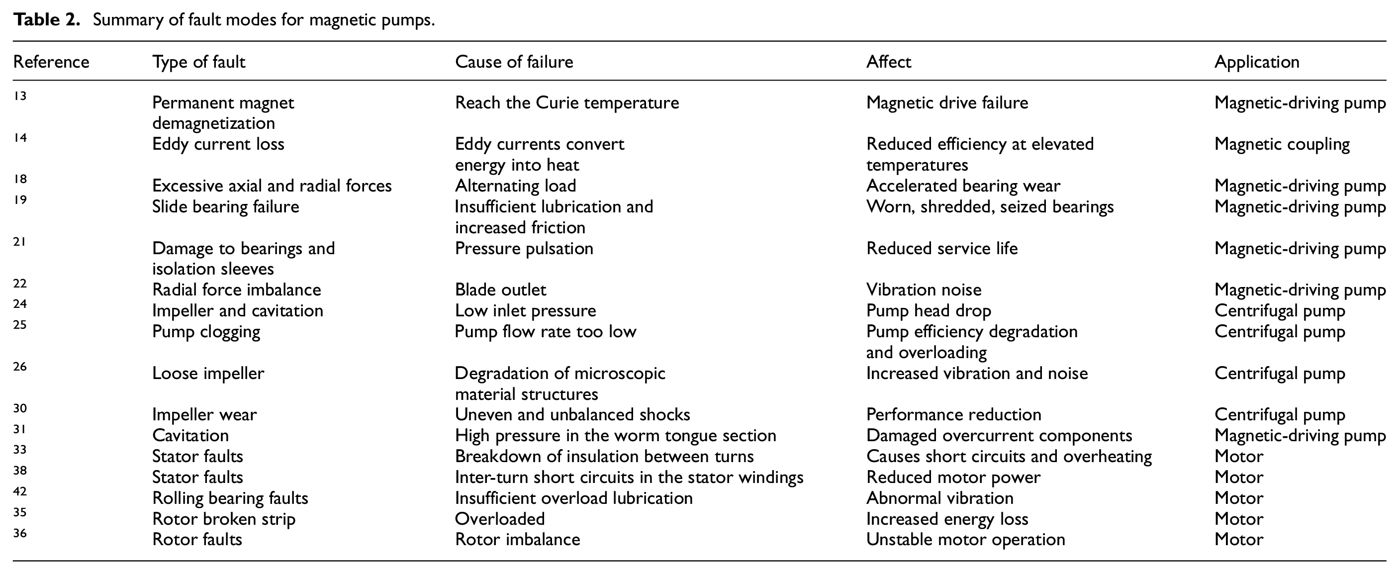
To sum up, fault modes of magnetic pumps are summarized in Table 2. Moreover, Figure 8 provides a more detailed category. However, these faults are not isolated and irrelevant. Such classification cannot reflect the interrelationship between premature fatigue and material failures. Figure 9 gives two networks illustrating the causes and effects of various faults mainly resulting from two main factors which are high temperature and insufficient lubrication to show the comprehensive correlation.
Summary of fault modes for magnetic pumps.
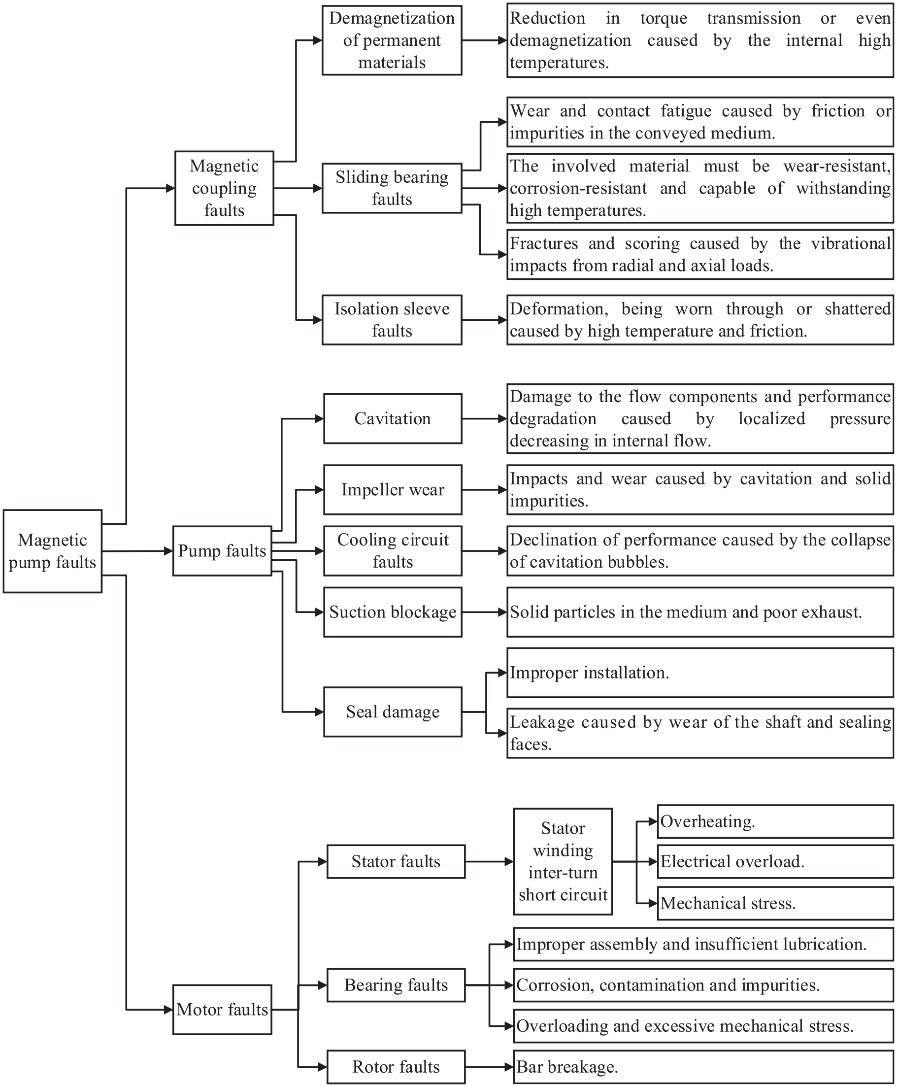
Summary of failure mode classifications for magnetic pumps.
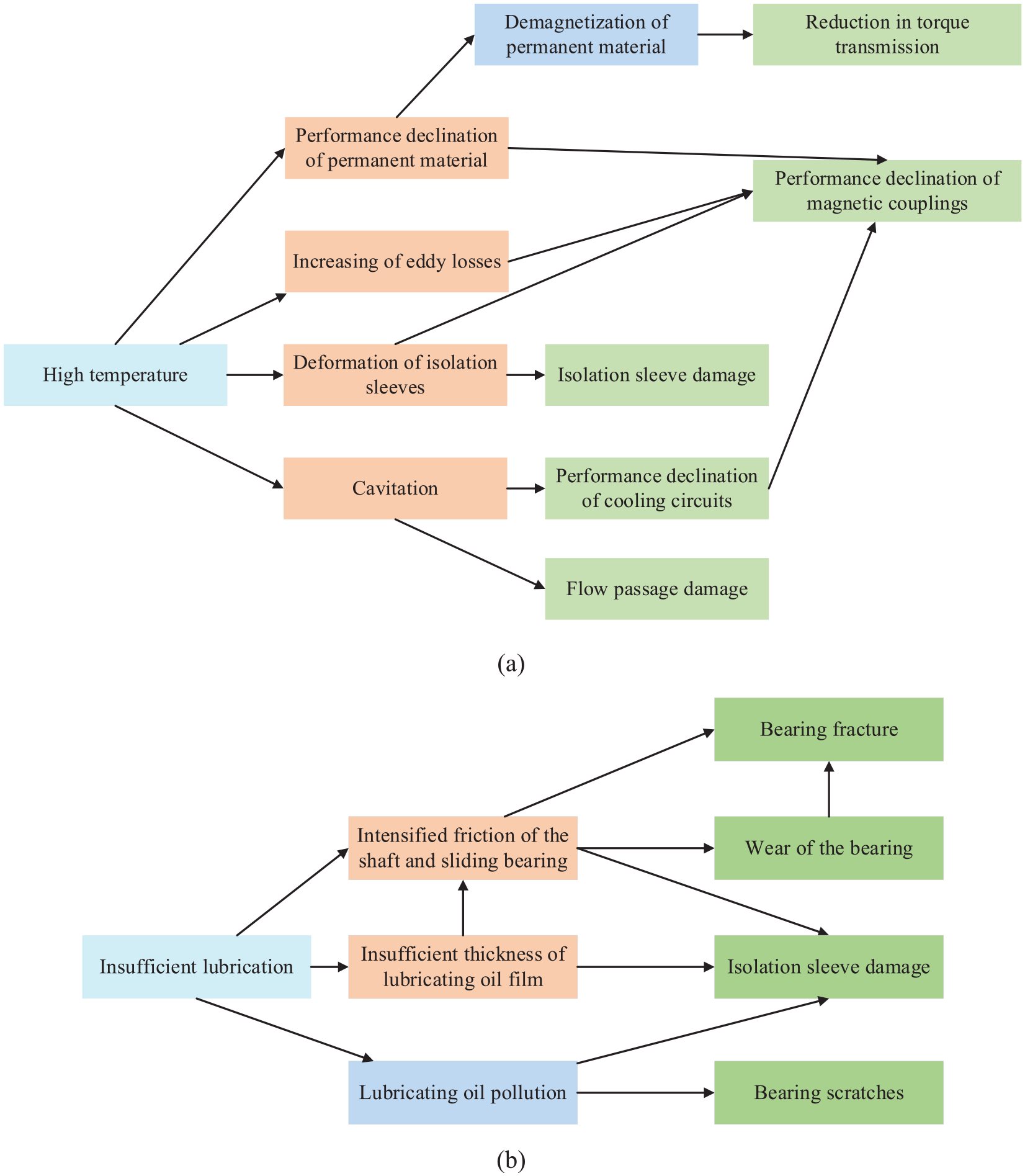
Correlation of magnetic pump faults: (a) high temperature and (b) insufficient lubrication.
Fault diagnosis technologies
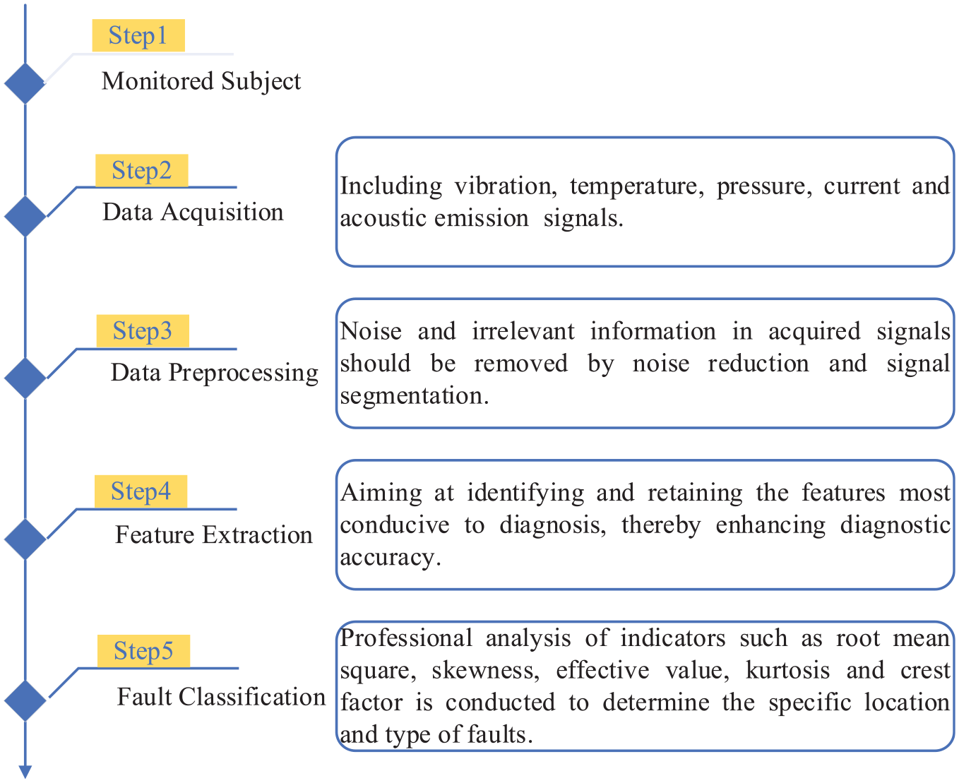
Magnetic pumps are renowned for their leak-proof design to convey hazardous and precious fluids for critical safety and environmental concerns. They are vital in the fields of aerospace, petrochemicals, healthcare, and defense, with their reliability and economic gains. However, magnetic pumps still face issues of eddy current losses raising temperatures, which affects magnet performance and causes damage to isolation sleeves. In addition, cavitation in pump cooling circuits must be considered. Research into fault diagnosis techniques is essential for maintaining pump stability. 48 The diagnostic process typically involves three key steps: data collection, feature extraction, and fault classification. According to the principles, fault diagnosis methods can be categorized into three types, which are model-driven, data-driven, and hybrid model-data-driven approaches, which are primarily summarized in Table 3, then clarified in detail afterward.
Summary of fault diagnosis methods for pumps.
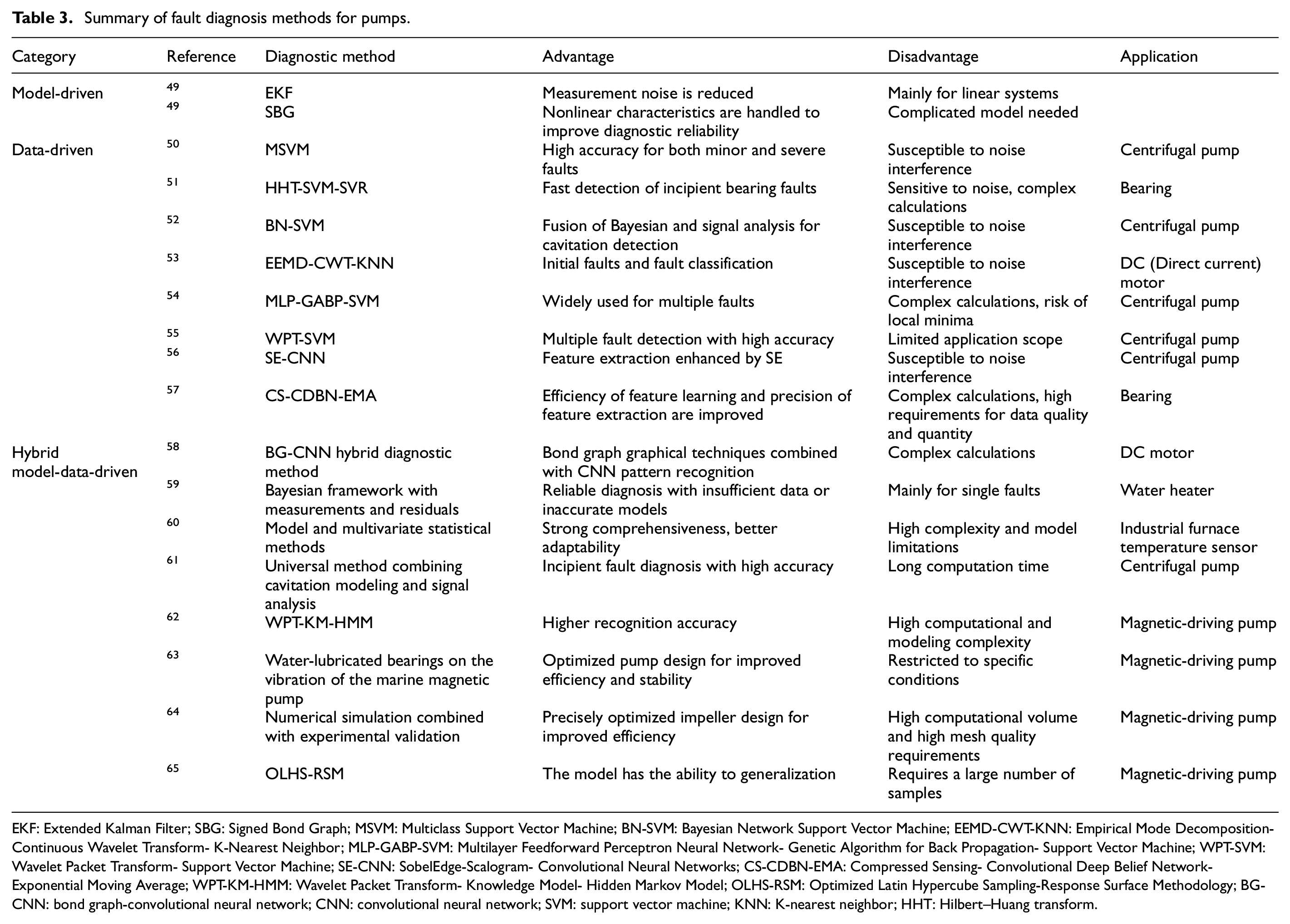
EKF: Extended Kalman Filter; SBG: Signed Bond Graph; MSVM: Multiclass Support Vector Machine; BN-SVM: Bayesian Network Support Vector Machine; EEMD-CWT-KNN: Empirical Mode Decomposition-Continuous Wavelet Transform- K-Nearest Neighbor; MLP-GABP-SVM: Multilayer Feedforward Perceptron Neural Network- Genetic Algorithm for Back Propagation- Support Vector Machine; WPT-SVM: Wavelet Packet Transform- Support Vector Machine; SE-CNN: SobelEdge-Scalogram- Convolutional Neural Networks; CS-CDBN-EMA: Compressed Sensing- Convolutional Deep Belief Network-Exponential Moving Average; WPT-KM-HMM: Wavelet Packet Transform- Knowledge Model- Hidden Markov Model; OLHS-RSM: Optimized Latin Hypercube Sampling-Response Surface Methodology; BG-CNN: bond graph-convolutional neural network; CNN: convolutional neural network; SVM: support vector machine; KNN: K-nearest neighbor; HHT: Hilbert–Huang transform.
Model-driven fault diagnosis methods
Model-driven fault diagnosis methods are based on the construction of equipment health models in Figures 10, 11, and 12 with dynamics, mechanics, and mathematics theory. These models simulate equipment operation and fault progression to analyze fault mechanisms. Residuals are differences between actual and predicted values for fault indicators. They should ideally be zero without faults but are nonzero when faults, disturbances, or model inaccuracies occur. Crafting precise mathematical models is challenging due to inherent errors and uncertainties, as not all uncertainties are measurable.
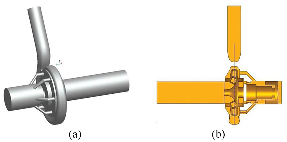
Three-dimensional model of full flow field in the magnetic pump: (a) 3D graphic and (b) sectional drawing. 8
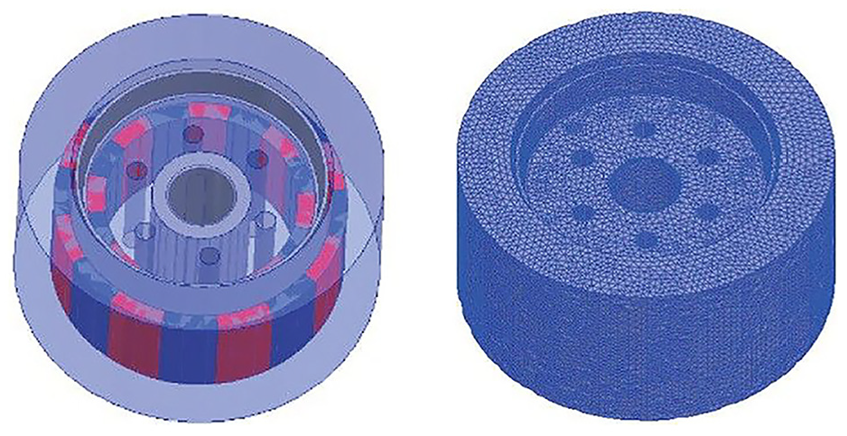
Magnetic pump computational domain: (a) assembly diagram and (b) mesh grid of the computational area. 15
Magnetic coupling 3D model (left) and mesh diagram (right). 14
Researchers have advanced model-driven diagnostics by developing statistical and interval methods to address uncertainty. 49 The former uses Gaussian variables, while the latter assumes bounded, manageable uncertainty. Both finite element and dynamic modeling simulate magnetic pumps’ internal fields for fault analysis. For example, Xu et al. 66 created a finite element model for a magnetic pump’s loss analysis to provide a theoretical diagnostic foundation. Jiaqiong et al. 15 used ANSYS for finite element modeling of magnetic coupling to study deformation under multi-field coupling shown in Figure 12. Theoretical benefits of modeling get declined, as system complexity increases and accurate modeling becomes more challenging. The need for more efficient techniques grows to address diagnostic demands and challenges.
Model-driven fault diagnosis is effective in simple systems with predictable faults and needs for real-time and understandable results. Accurate models are built based on system mechanisms, allowing deep fault analysis. This method works well with linear faults. Less dependency on operational data makes it robust against data collection challenges. For magnetic pumps, this method compensates for sensor installation difficulties due to effective sealing, aiding in fault diagnosis. However, it faces challenges with the pumps’ nonlinearity, requiring significant expertise for precise modeling. It also has limitations in diagnosing multiple or simultaneous faults, as usually considering faults in isolation, not accounting for their potential interactions.
Data-driven fault diagnosis methods
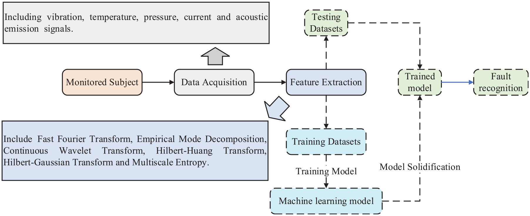
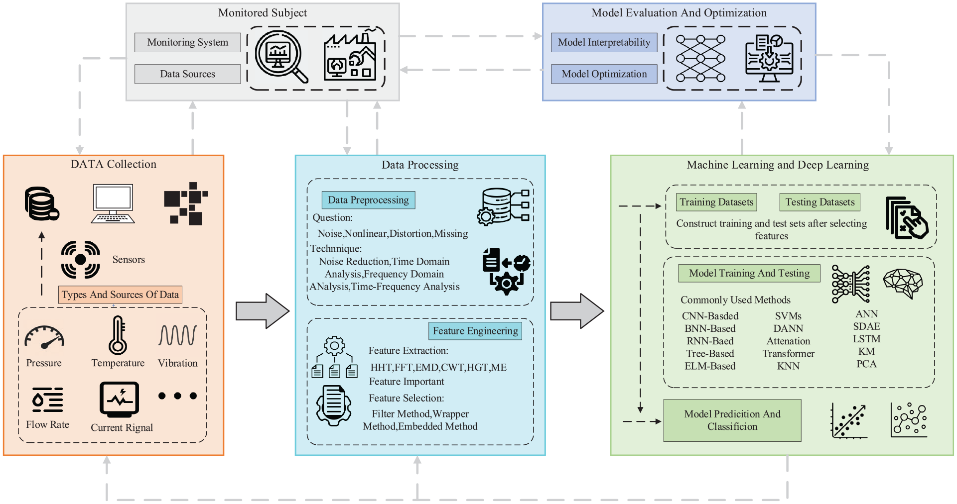
Data-driven fault diagnosis methods have abandoned the complex modeling, instead opting to collect operational data. As illustrated in Figure 13, these methods are based on experimental data collection from key operational areas of the equipment, including temperature, imagery, vibration, acoustic emission signals, and current. Signals generated by magnetic pumps are nonlinear, nonstationary, and nonperiodic, making it challenging to extract fault information directly. Thus, feature extraction becomes a crucial step for accurate fault diagnosis. Common feature extraction techniques include fast Fourier transform, empirical mode decomposition (EMD), continuous wavelet transform, HHT, Hilbert–Gaussian transform, and multiscale entropy. Following feature extraction, establishing a correspondence between fault features and patterns is equally vital. Common classification methods include RF, K-nearest neighbors (KNNs), 67 self-organizing maps, support vector machines (SVMs), and backpropagation neural networks.
Procedures of fault diagnosis based on signal processing methods.
For example, Ahmad et al. 50 introduced a feature extraction technique based on correlation coefficients between a healthy baseline and original statistical signal features for pump fault diagnosis. Soualhi et al. 51 applied the Hilbert–Huang Transform to motor current signals, integrating them with autoregressive models and SVM for bearing fault identification. Safizadeh et al. 52 enhanced cavitation detection accuracy by combining vibration and current signals using Bayesian theory. Shifat and Hur 53 achieved a 98% diagnostic accuracy rate by classifying brushless DC motor vibration signals with a combined EMD (IEMD) and KNN approach.
Recently, advancements in artificial intelligence (AI) technology and hardware have greatly progressed data-driven fault diagnosis methods, particularly ML and DL. As shown in Figure 14, ML algorithms sift through large datasets to uncover patterns for prediction and decision-making. DL, a subset of ML depicted in Figure 15 and based on Artificial Neural Networks (ANNs), manages larger datasets and complex cognitive tasks. Introduced by Hinton in 2006, DL employs multi-layered networks to extract features and learn nonlinear relationships for fault categorization. 68 Through training, DL models uncover sample features to boost fault classification and prediction capabilities. 69 Common DL methods include Deep Neural Networks (DNN), Deep Belief Networks (DBN), Stacked Autoencoders (SAE), Convolutional Neural Networks (CNN), and Recurrent Neural Networks (RNN). For example, ALTobi et al. 54 compared MLP neural networks with three wavelet transformations for feature extraction, then combined genetic algorithms with SVM for pump fault identification. Zhu et al. 55 combined continuous wavelet transform with SVMs to enhance pump fault diagnosis accuracy. Zaman et al. 56 fused signal processing with DL, using Stockwell transform and Sobel filtering to generate SobelEdge scale maps for CNN classification, achieving a 99.68% diagnostic accuracy. Shao et al. 57 integrated compressed sensing with DBN for improved bearing fault diagnosis. Xiao et al. 70 proposed a novel induction motor fault diagnosis framework by integrating empirical statistical parameters, recursive quantification analysis, and LSTM neural networks, tested across various fault types to confirm the method’s effectiveness and superiority.
Procedures of fault diagnosis based on ML algorithms.
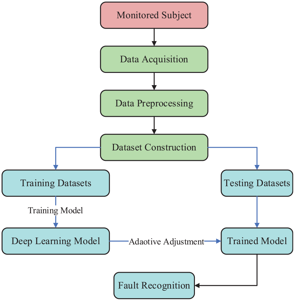
Procedures of fault diagnosis based on DL algorithms.
DL algorithms decrease dependence on diagnostic expertise and effectively process machinery’s nonlinear and nonstationary signals, emerging as a leading research area in fault diagnosis. However, some studies lack deep analysis into the root causes that enhance diagnostic accuracy, merely using experiments and datasets for validation. Future research should delve deeper into optimizing these methods for higher precision and reliability in fault diagnosis. 71
Data-driven fault diagnosis is particularly effective in complex systems with many parameters and varying operating conditions. Larger datasets can refine diagnostic reliability and precision. Both current and historical data are processed by signal analysis and ML methods to identify faults without system modeling. However, the use of black-box ML models focuses on results rather than providing mechanistic insights into fault patterns, making it suitable for quick diagnostics where deep analysis is not required. Data-driven methods are beneficial for magnetic pumps, which require substantial operational data like pressure and vibration signals to train ML models. The variety of potential faults in magnetic pumps facilitates the collection of extensive fault data, which aids in continuous model updates and enhances diagnostic accuracy and speed. Early fault detection is crucial to prevent minor inefficiencies from escalating into severe issues. While data-driven methods offer rapid diagnostics, they face challenges in interpreting failure mechanisms and ensuring data quality.
Hybrid model-data-driven fault diagnosis methods
Model-driven methods excel at swift fault detection and diagnostics but are prone to false alarms due to interference and modeling errors. Data-driven methods leverage AI to offer high-precision diagnostics from extensive training data but struggle with obtaining early fault data. 72 A hybrid model-data-driven fault diagnosis approach has been suggested to combine the strengths of both methodologies, which leverage physical models for in-depth information and data-driven learning for enhanced diagnostic accuracy and robustness. There are mainly two integration approaches in hybrid-driven methods:
Utilizing model-based methods to generate residual data, which is then preprocessed for data-driven fault diagnosis. As shown in Figure 16, Dash et al. 58 used a bond graph to generate residual data and established a bond graph-CNNs (BG-CNNs) hybrid fault diagnosis method by employing CNN for fault diagnosis isolation.
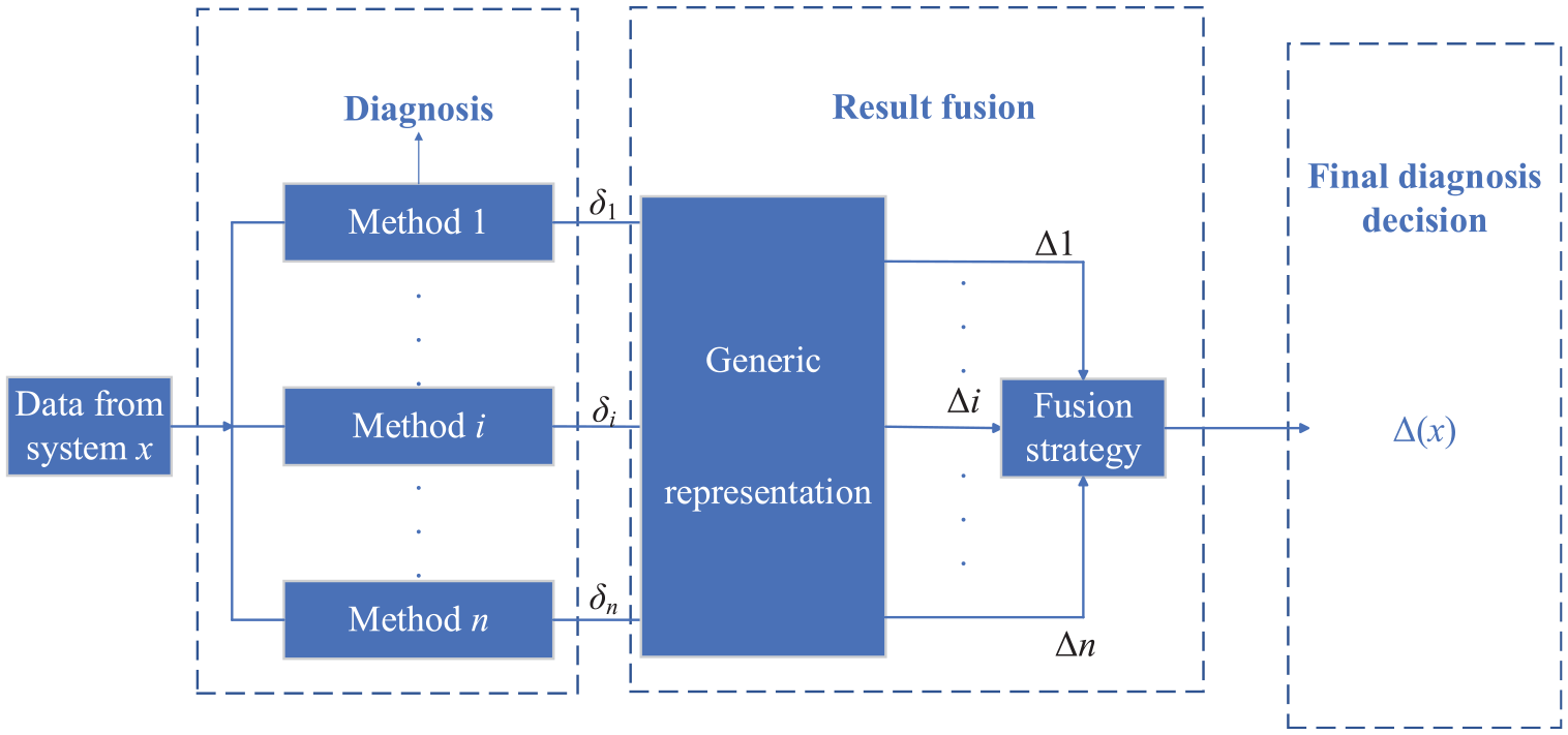
The second integration is versatile, as depicted in Figures 17 and 18. Various diagnostic techniques from system measurements are combined to boost reliability. Atoui et al. 73 enhanced decision reliability by linking parameters from data-model-driven methods using Conditional Gaussian Networks and Bayesian network modeling. Schubert et al. 59 suggested a unified fault diagnosis scheme that merges model and data-driven approaches, utilizing subspace models and state detectors, and generating multivariate augmented residuals for fault diagnosis. Ghosh et al. 60 combined model-based Kalman filtering with data-driven methods such as principal component analysis (PCA). 74 ANN and SVM, as shown in Figure 19. All methods use online data as input and classify conditions for a comprehensive outcome through decision fusion. The authors established a numerical simulation model for gas-liquid two-phase flow under cavitation conditions to extract the frequency of bubble detachment. Combined with experimental signal analysis, a monitoring index for the initial state of cavitation was proposed through the model-data-driven method. 61
A unified ML framework for magnetic pump fault diagnosis. 2
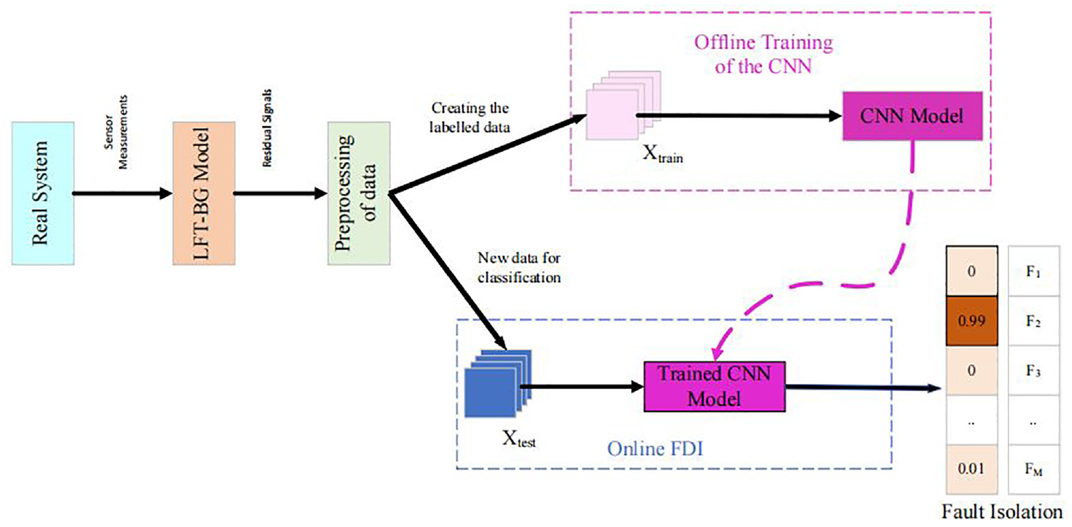
Flow chart of the BG-CNN fault diagnosis method. 58
Integration framework of the hybrid fault diagnosis method. 61
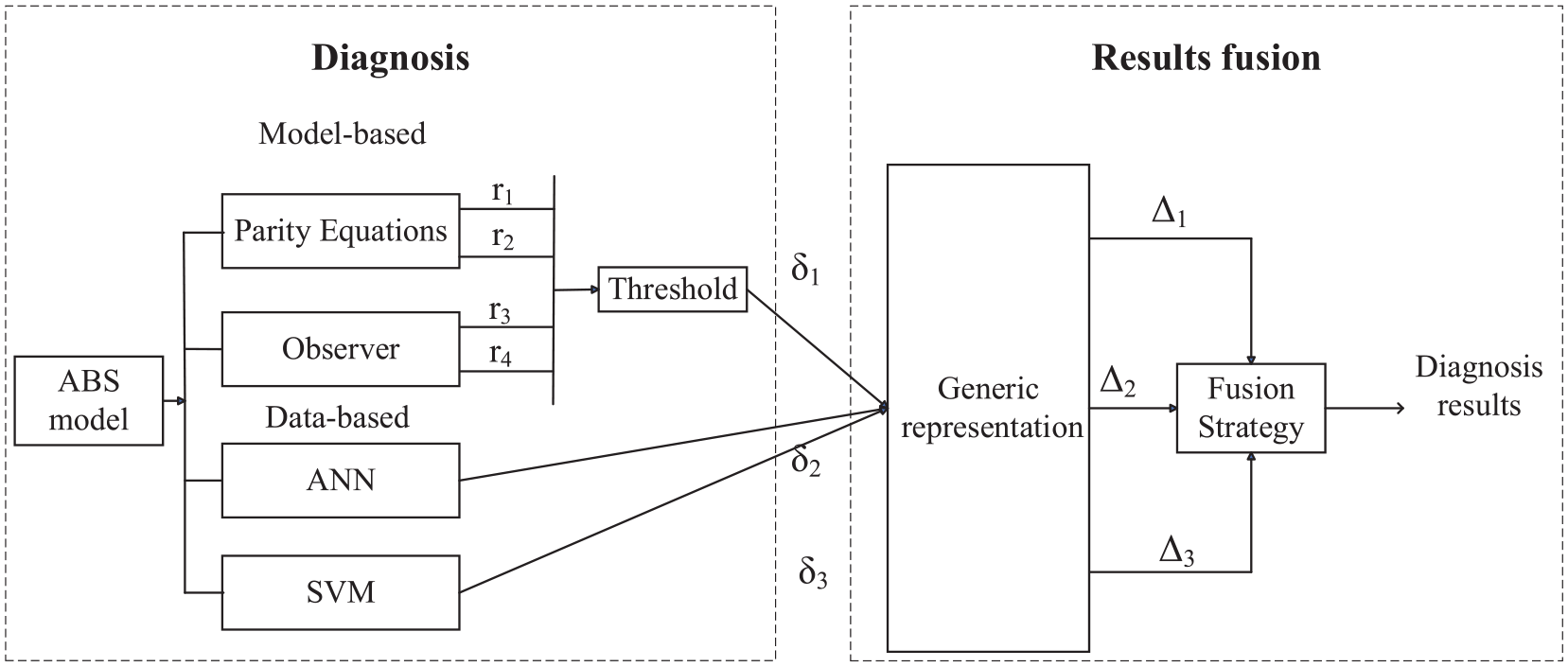
Flowchart of fault diagnosis method combining odd-even space and observation methods with ANN and SVM. 61
The hybrid model-data-based method is ideal for scenarios with limited operational data, combining model knowledge with scarce data to generate supplemental fault data for diagnosis, thus reducing dependence on large datasets. It also enhances interpretability and diagnostic speed by integrating model and data analysis, which is vital for understanding fault mechanisms in critical equipment. Moreover, this method improves by refining the model with data diagnosis and vice versa, leading to more accurate reflections of actual conditions. However, integrating model and data-driven approaches is complex and requires highlighting each strength. Challenges include creating high-precision models amidst industrial complexity, which new techniques such as model disassembly and point cloud reverse modeling aim to address. In addition, managing extensive data requires effective database and storage solutions to avoid redundancy and extract valuable information. Lastly, a unified framework is needed to integrate data-driven and model-based approaches across various applications, rather than relying on custom solutions. Research in this area is limited, necessitating further exploration.
Conclusions and outlooks
This article has reviewed the fault modes of magnetic pumps, as well as the causes and impacts on system performance. Moreover, the principles and application cases of current fault diagnosis methods are analyzed. Through comparative analysis, it has been found that although existing model-based and data-driven fault diagnosis methods each have their advantages, they still have limitations in terms of accuracy and practicality. The conclusions are as follows:
To ensure the stable operation of magnetic pumps, fault diagnosis and prediction of the cooling circuit are crucial. Despite research progress, magnetic pumps are prone to high temperatures at high speed, which can cause faults. Their unique designs, such as cooling circuits, may fail due to the collapse of bubbles caused by cavitation. Further research is necessary to improve diagnostic accuracy.
Instant early warning of faults is essential for improving the precision and speed of magnetic pump fault diagnosis, especially for issues of sliding bearing wear and permanent magnet demagnetization, which can be prevented through temperature monitoring.
Current fault diagnosis methods are divided into three categories, which are model-driven, data-driven, and hybrid-driven. Model-driven methods are less commonly used due to limitations in model accuracy and versatility. Data-driven methods are widely applied due to their high accuracy and speed. Although hybrid-driven methods have much potential, there is still little research to effectively integrate the advantages of models and data to enhance diagnostic efficiency.
In the industrial environment, the reliability and safety of mechanical equipment are extremely important. Due to their leak-proof characteristics, magnetic pumps have been widely used in various fields. To ensure the normal operation of magnetic pumps, it is very necessary to predict early faults. The future prospects of magnetic pump fault diagnosis research are as follows:
With the development of Industry 4.0 and intelligent manufacturing, intelligent fault diagnosis systems integrated with smart sensors and AI algorithms will become the key to the development of magnetic pump fault diagnosis technology. This will improve the speed and accuracy of fault diagnosis meanwhile reducing maintenance costs and enhancing the reliability of the system. The hybrid model-data-based fault diagnosis method can combine the advantages of both methods and more research is needed.
Future research should focus more on the development of new sensor technologies, DL algorithms, and self-adaptive fault diagnosis models for the changing industrial environments and operating conditions. At the same time, interdisciplinary research methods, such as combining material science, fluid dynamics, and data science, will provide a more comprehensive solution for magnetic pump fault diagnosis.
With market potential, policy support, talent reserves, and a complete industrial chain, China has established a solid foundation for innovation and industrialization in the field of magnetic pump technology. Faced with challenges of technological innovation, material dependence, market docking, intellectual property rights, standard setting, environmental safety, and international competition, China will continue to break through core technologies, strengthen international cooperation, optimize R&D market docking, protect intellectual property rights, and participate in the formulation of international standards, thereby enhancing the global competitiveness and market influence of magnetic pump technology.
An industry-specific large-scale knowledge model (ILKM) framework helps to address the sophisticated needs of Industry 4.0 and smart manufacturing. 75 ILKM integrates AI, ML, and language modeling with industry expertise, following “6S principles” for its development. It contrasts with large language models in purpose and application. An ILKM tailored for magnetic pump failures can boost fault management efficiency by analyzing industrial data and offering customized solutions, aiding in more effective maintenance and operations. 76 ILKM’s role in intelligent manufacturing is promising and can substantially support industrial advancement.
Open-source datasets are crucial to magnetic pump failures. Datasets provide researchers with a wealth of experimental data for performance enhancement and predictive maintenance. They also boost diagnostic accuracy, aid in crafting more effective models, and increase equipment reliability and safety. Moreover, these datasets enable multimodal ML by combining different data types like vibration, temperature, and current for decision-making. This approach fosters knowledge sharing and collaboration, reducing redundancy, and enhancing research efficiency.
Footnotes
Declaration of conflicting interests
The author(s) declared no potential conflicts of interest with respect to the research, authorship, and/or publication of this article.
Funding
The author(s) disclosed receipt of the following financial support for the research, authorship, and/or publication of this article: This work supported by the Postgraduate Research & Practice Innovation Program of Jiangsu Province (SJCX24_2480), the Natural Science Foundation of Jiangsu Province (BK20201007), and Major Basic Research Project of the Natural Science Foundation of the Jiangsu Higher Education Institutions (20KJD470002) of China.