
Abstract
Prestressed steel tendons, as the key load-bearing component of prestressed concrete girders, will inevitably suffer damage, threatening the bridge’s safety and durability. Existing methods of locating damage to prestressed steel tendons necessitate the arrangement of numerous acoustic emission (AE) sensors outside the girder. To reduce the AE monitoring costs of the actual bridge, a dual-sensor AE localization method is proposed to monitor which steel tendon is damaged in a prestressed concrete girder. The key to implementing the proposed method is using a waveguide rod to preconnect the prestressed steel tendons inside the girder. To validate the feasibility of the proposed method, simplified positioning tests were performed on a test platform connected by waveguide rods, which includes connection forms of rebar welding, rebar adhesion, steel plate welding, and steel plate adhesion. Furthermore, the practicality of the proposed method was demonstrated by preinstallation of waveguide rods within a posttensioned prestressed hollow slab. Results indicate the dual-sensor localization method could precisely determine which prestressed steel tendon is suffering damage regardless of ambient AE noise, where AE wave velocity for localization could be selected empirically. The proposed method helps to reduce the cost of AE-based tendon breakage monitoring of bridges.
Keywords
Introduction
Bridges are vital in China, forming the essential component of transport infrastructure and driving economic, social, and cultural development.1–3 Prestressed concrete girders are widely used in modern bridge engineering because they improve the bridge’s crack resistance, stiffness, and load capacity through applied prestresses.4,5 However, with increasing service time, these girders will inevitably be damaged under environmental change and vehicle loads, that is, concrete cracking 6 and corrosion or wire breakage of the prestressed steel tendons. 7 Damage to the steel tendons, the crucial component of prestressed concrete girders, compromises the girder’s safety, suitability, and durability. 8 Therefore, long-term monitoring and damage diagnosis for the prestressed steel tendons are required to maintain safe operations for the numerous bridges.
Internal material damages to the structure, such as wire breakage of the prestressed tendons, release the energy to the surrounding area and propagate as elastic waves, forming an acoustic emission (AE) source.9,10 Monitoring and localization of AE sources, such as damaged prestressed steel tendons, enable immediate measures of remediation against further damage to the bridges.11,12 Currently, time difference localization is usually adopted to localize AE sources, 13 and it is classified into one-dimensional linear, 14 two-dimensional planar, 15 and three-dimensional spatial 16 localization based on specific structural forms.
The localization of damage sources in prestressed concrete girders (e.g., girder concrete cracking and tendon wire breakage) is a complex multidimensional problem. Currently, there are fewer studies to localize damage sources in concrete beams using AE techniques. Among these studies, scholars have focused on damage localization methods for concrete cracks,17,18 mostly on scaled-down model beams,19,20 with little research on full-scale girders. Das et al. 21 proposed a new technique for precise pickup of arrival time based on wave power to locate web cracks in a 100-cm-long steel-fiber concrete beam using eight sensors. To evaluate and quantify the localization accuracy of AE sources in concrete structures, Zhang et al. 22 defined an indicator, named characteristic error, and verified the indicator by using 14 AE sensors for the two-dimensional localization of hammering signals on a cracked concrete beam. Zhang et al. 23 proposed a simple probabilistic method to locate the concrete cracks, considering the source localization error. The method was applied to the destructive testing of a full-scale reinforced concrete beam using 13 sensors for the two-dimensional localization of cracks in the beam web. Barbosh et al. 24 developed an improved preprocessing framework that combines empirical modal decomposition with the source localization model to localize cracks in concrete beams. Based on the proposed framework, four AE sensors were used to locate the web cracks of two small (355 mm) and two large (2440 mm) concrete beams in two dimensions.
Generally, numerous sensors are required for multidimensional localization of structural damage sources using AE techniques.25,26 For example, in the case of the defect localization in large-diameter pipelines or pressure vessels, Zhang et al. 27 presented a strategy for phased array AE localization to locate the axial and radial locations of the defect in hollow structures using eight sensors according to the practical path of AE wave propagation. Liu et al. 28 studied the wave propagation path in the parallel steel wire bundle and proposed a three-dimensional localization algorithm using four AE sensors to localize the damage source. Manuello et al. 29 adopted a multichannel AE acquisition system with wireless transmission and on-site data processing capabilities to monitor the damage evolution of two precast concrete arch members in a road tunnel. This acquisition system performed three-dimensional precise localization of active cracks using eight AE sensors. However, for one-dimensional linear structures, damage source localization can be achieved with only two or even one sensor. 30 Quy et al. 14 captured cracking signals using two R15i-AST sensors mounted at each end of a fluid pipeline and then analyzed the signals in the time–frequency domain to obtain AE events, which were then used to locate the damage source with the time difference of arrival (TDOA) technique. With the linear localization method, Qin et al. 31 calculated the velocity of propagation along the grain direction of the AE signal in wood. Zhang et al. 32 used a single AE sensor to identify the occurrence and propagation of defects within railroad switch rails based on dispersion characteristics and time–frequency properties of AE signals induced by defects. Based on the examination that the TDOA can be determined by the arrival times of different modes, that is, A0 and S0 modes, in an AE signal, Yu et al. 33 established an AE source one-dimensional localization method using only one single fiber-optic Bragg grating sensor to assess the damage in the carbon fiber reinforced plastic laminate.
To summarize, except for one-dimensional linear localization, two-dimensional planar and three-dimensional spatial localization require numerous AE sensors with high monitoring costs. For the localization of damaged steel tendons inside the girder, numerous AE sensors would need to be arranged outside the prestressed concrete girders. To reduce the cost of AE monitoring in actual bridges, this paper proposed a dual-sensor AE localization method to localize the damaged steel tendon inside prestressed concrete girders with the help of the waveguide rod.
Methodology
Benefits of using waveguide rods
A waveguide rod of appropriate length is selected to preconnect four prestressed steel tendons by welding or adhesion according to the relative position of steel tendons in prestressed concrete girders. The waveguide rods are easily and quickly installed before the final anchorage sealing of the full-scale girder. In this way, the localization of the damaged steel tendon is transformed from a two-dimensional planar localization problem to a one-dimensional linear localization problem. Two AE sensors, Sensor-1 and Sensor-2, are positioned on the waveguide rod, as shown in Figure 1. The prestressed steel tendon is an integral structure consisting of multiple prestressed steel strands, usually used to transmit the prestress.
Schematic diagram of the dual-sensor AE localization method.
One-dimensional linear localization principle
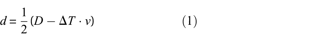
The one-dimensional linear localization approach only uses two AE sensors and a single time difference, which is the simplest time difference localization method, 33 and its localization principle is shown in Figure 2. The distance between Sensor-1 and Sensor-2 is D. Supposing that an AE damage source exists between these two sensors, the time of arrival for damage signals collected by these two AE sensors would be T1 and T2. And the TDOA ΔT = T2 − T1. According to Equation (1) and the AE wave propagation velocity v inside the structure, the location d of the AE source could be determined.
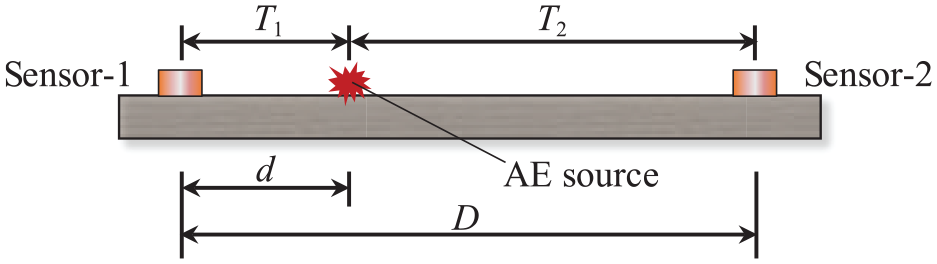
The one-dimensional linear localization principle.
The dual-sensor AE localization method using waveguide rods
Based on the conventional one-dimensional linear localization principle, a novel dual-sensor AE localization method using waveguide rods is proposed to localize the damaged prestressed steel tendon only by the TDOA ΔT of two AE signals. There are three advantages to this localization method as follows.
With only two AE sensors, the damage condition of the steel tendons of the whole prestressed concrete girder can be directly monitored.
The influence of environmental noises on the AE signal does not need to be considered.
Maintenance and replacement of the AE sensors is easy.
The specific method is as follows.
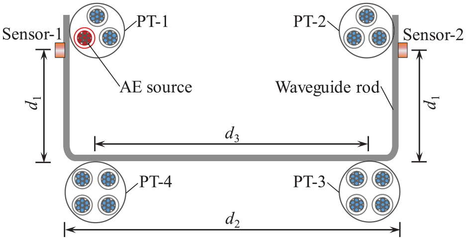
As illustrated in Figure 3, when damage such as wire breakage occurs in the prestressed steel tendon PT-1, the damage signal will first be transmitted from the steel tendon to the anchorage, then to the waveguide rod from the anchorage, and eventually be received by AE sensors located at the ends of the waveguide rod. The times of arrival for the damage waves to Sensor-1 and Sensor-2 are T1 and T2, respectively, and the TDOA of the damaged signal is ΔT1. Detailed explanations of the acronyms in equations can be found in Table A1.
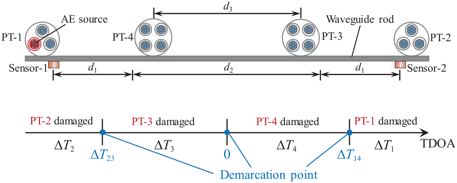
Detailed explanations of the dual-sensor AE localization method.
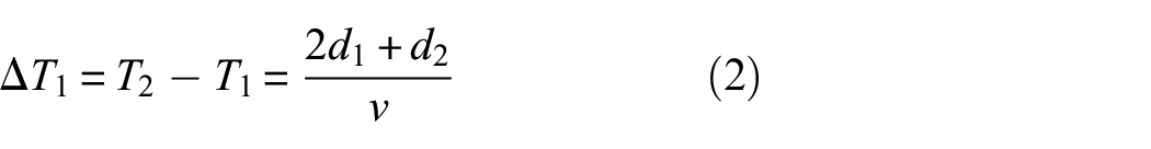
Similarly, when the prestressed steel tendons PT-2, PT-3, and PT-4 are damaged, the TDOA of AE signals are ΔT2, ΔT3, and ΔT4, respectively:
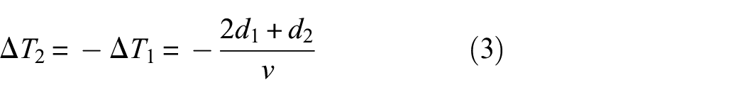
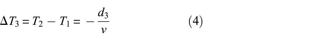
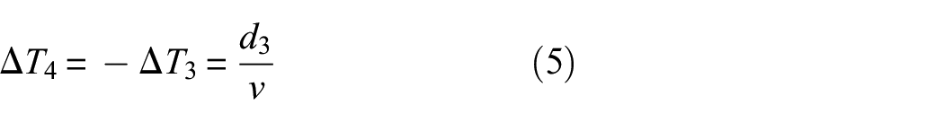
where d1 is the length from the bending point of waveguide rods to the AE sensor; d2 is the length between bending points of waveguide rods; d3 is the distance between prestressed steel tendons PT-3 and PT-4; and v is the AE signal propagation velocity in the waveguide rod.
The TDOA has different values for the steel tendons at the distinct locations inside the prestressed concrete girders. It could be concluded that the damaged steel tendon located at the right or left side of prestressed concrete girders can be identified by the positive and negative of the TDOA. Furthermore, the damaged steel tendon at the top or bottom can be determined by the absolute value of the TDOA.
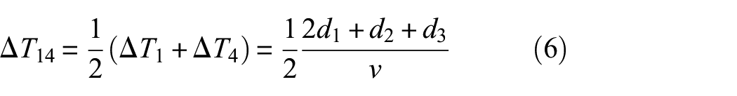
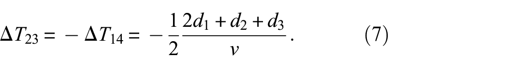
Therefore, there is no need to measure the AE wave propagation velocity inside waveguide rods; the mean value ΔT14 of the TDOA ΔT1 and ΔT4 can be used to determine the damaged signal coming from the steel tendon PT-1 or PT-4. Similarly, the mean value ΔT23 of the TDOA ΔT2 and ΔT3 can be used as a demarcation point for determining damaged signals coming from the steel tendon PT-2 or PT-3:
For actual prestressed concrete girders, when TDOA ΔT of the real damaged signals received by two sensors meets ΔT14 < ΔT, it can be determined that PT-1 is damaged. Similarly, when ΔT < −ΔT14, PT-2 is damaged; when −ΔT14 < ΔT < 0, PT-3 is damaged; when 0 < ΔT < ΔT14, PT-4 is damaged. The number of prestressed steel strands does not affect the propagation path of the AE signal; thus, it will not affect the positioning results. Theoretically, this localization method can accurately localize the damaged prestressed steel tendons within the bridge cross section, and the effective identification range can reach the entire bridge cross section.
Experimental validation
Experimental design
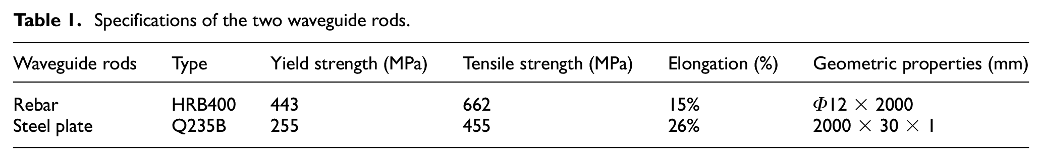
To avoid the influence of concrete and ordinary steel bars on the dual-sensor AE localization method of damaged steel tendons, this paper built an experimental platform to verify the feasibility of the proposed localization method based on the relative position of prestressed steel tendons in a prestressed concrete girder, as shown in Figure 4. To investigate the effect of the type of waveguide rods and their fixing method on the proposed localization method, four various connection forms were used to connect prestressed steel tendons, namely, rebar welding, rebar adhesion, steel plate welding, and steel plate adhesion. Table 1 shows the specific parameters of waveguide rods. The welding process was shielded metal arc welding. For adhesion, a modified acrylate adhesive was used to bond waveguide rods to the anchorage. The prestressed steel tendons were separated from the erection bars by rubber mats to prevent energy dissipation caused by the propagation of AE waves through the erection bars.
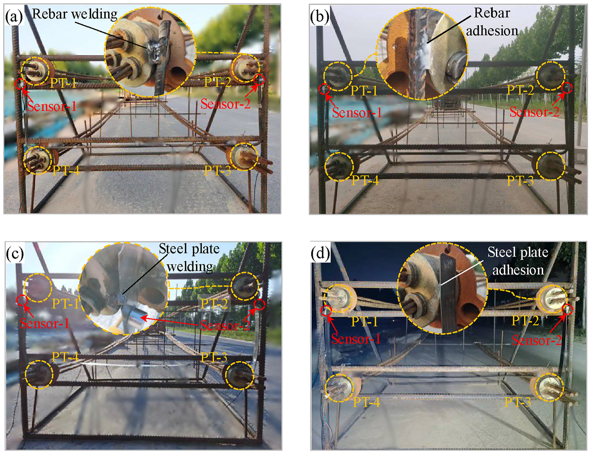
Experimental platform: (a) rebar welding, (b) rebar adhesion, (c) steel plate welding, and (d) steel plate adhesion.
Specifications of the two waveguide rods.
AE monitoring system
The DS5-16B full-information AE signal analyzer and RS-2A AE sensors were used in this experiment to record and acquire AE signals. The AE monitoring system is shown in Figure 5. A 40-dB gain amplifier was used to connect the sensors and the AE signal analyzer. The acquisition time of AE signals was longer than the pencil lead break (PLB) time, 34 with a sampling rate of 2.5 MHz. The peak discrimination time was set at 300 µs, the hit definition time was set at 600 µs, and the hit locking time was set at 1000 µs based on the results of previous research. 28 AE sensors were mounted with the surfaces of waveguide rods decontaminated and a thin layer of Vaseline uniformly applied to improve the coupling between the surfaces of waveguide rods and AE sensors. 35 Adhesive tape was used to secure the sensor to prevent it from falling off.
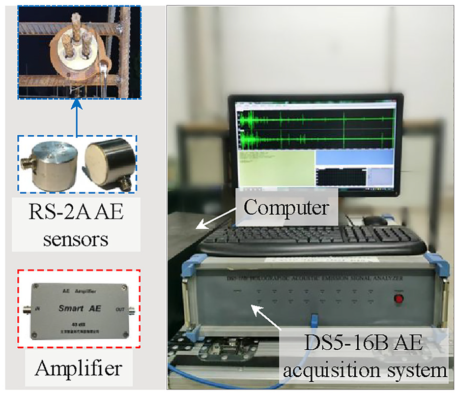
AE monitoring system.
Experimental procedure
The dual-sensor AE localization method’s verification tests were conducted for four connection forms shown in Figure 4. Two AE sensors were arranged on the surface of waveguide rods during the test, located 2 cm below prestressed steel tendons PT-1 and PT-2, respectively. The PLB was used as the artificial damage source to stimulate AE waves.36,37 An HB pencil with a length of 2.5 mm and a diameter of 0.5 mm was used for the test, and the PLB point was located on the prestressed steel tendons behind the anchorage, and the lead was broken three times for each steel tendon, as shown in Figure 6.
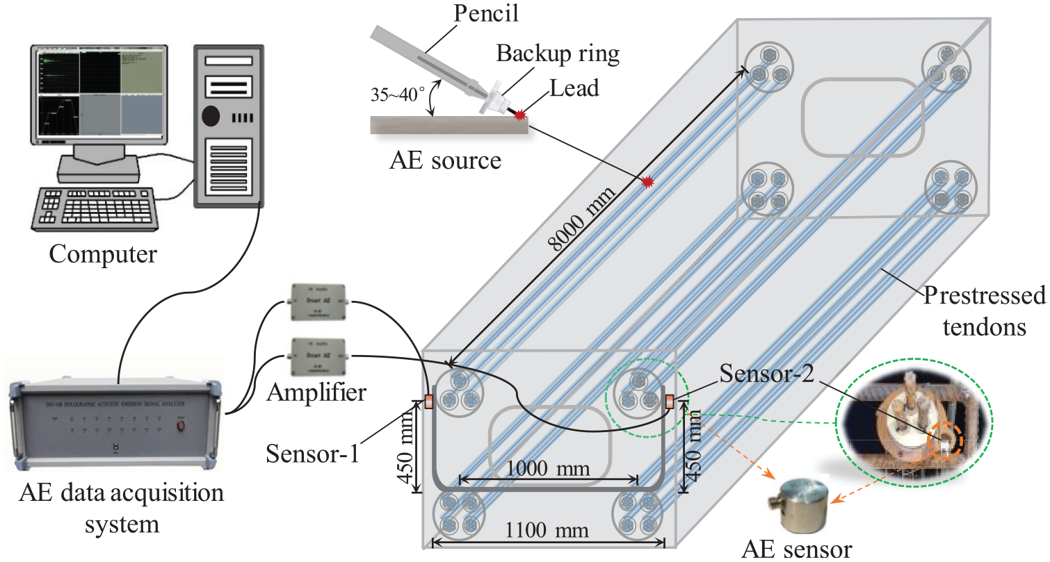
Schematic of test setup.
Figure 7 shows the waveforms of PLB signals collected from four prestressed steel tendons. The fluctuations are relatively consistent, and the amplitudes of each PLB signal are close to each other by analyzing the waveforms of the acquired PLB signals. Therefore, the PLB signals can be considered to have good repeatability.
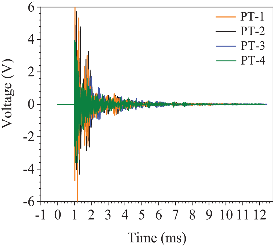
The PLB signals waveforms.
Experimental results
Positioning results under rebar welding
Localization with TDOA of head wave
The measurement of the arrival time of AE signals is the basis for AE damage source localization. The head wave of AE signals is the P-wave. Due to the most accurate pickup of the P-wave arrival time in measured signals, the TDOA of the P-wave is used to locate damaged steel tendons to verify the feasibility of the proposed localization method.37,38ΔT = TH2 − TH1 is the head wave TDOA. TH1 is the head wave arrival time captured with Sensor-1, and TH2 is the head wave arrival time captured with Sensor-2. The time when the waveform of the AE signal started to increase significantly as the head wave arrival time was manually selected.
The velocity of the P-wave is typically 5880 m/s in steel. The measured lengths for waveguide rods are 450 mm for d1, 1100 mm for d2, and 1000 mm for d3. Based on Equations (6) and (7), the theoretical values ΔT14 and ΔT23 at the demarcation point are 0.255 and −0.255 ms, respectively. The TDOA of head waves for different damaged prestressed steel tendons are different, and the measured values are easily affected by steel type and ambient temperature. As shown in Table 2, for the prestressed steel tendon PT-1, PT-2, PT-3, and PT-4, the measured TDOA ΔT1, ΔT2, ΔT3, and ΔT4 are 0.366, −0.362, −0.209, and 0.218 ms, respectively. Figure 8 shows the localization results of four damaged prestressed steel tendons using the TDOA of head waves. The measured mean values ΔT14 of 0.292 ms and ΔT23 of −0.292 ms are taken as demarcation points for determining the damaged steel tendon. Measured values are close to the theoretical values. When head waves TDOA of damaged signal meets 0.292 ms < ΔT, PT-1 is damaged; similarly, when ΔT < −0.292 ms, PT-2 is damaged; when −0.292 ms < ΔT < 0, damage occurs in PT-3; PT-4 is damaged, when 0 < ΔT < 0.292 ms.
Measured values of the head waves TDOA.
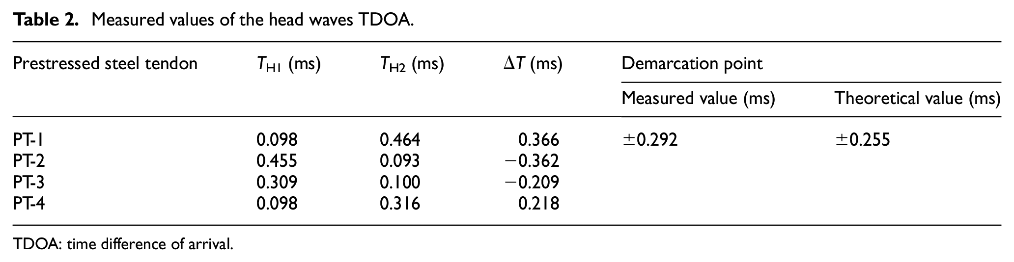
TDOA: time difference of arrival.
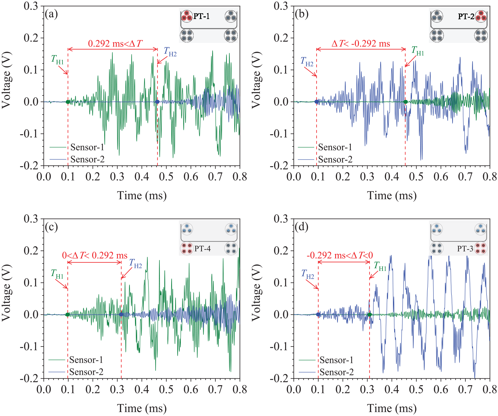
Localization results using the TDOA of head waves: (a) PT-1, (b) PT-2, (c) PT-4, and (d) PT-3.
In conclusion, the TDOA of head waves has different value ranges when damage occurs in distinct prestressed steel tendons. Four prestressed steel tendons are preconnected by waveguide rods, and then, through the TDOA of head waves captured with Sensor-1 and Sensor-2, we can accurately identify the specific prestressed steel tendon that has been damaged.
Localization with TDOA of maximum amplitude
In-service prestressed steel tendons in girders are exposed to high-noise environments, which can interfere with the AE signal of damage to the prestressed steel tendons. The threshold of the AE acquisition system must be set higher when accounting for ambient noise. This will lead to a relatively large error in the TDOA of head waves, affecting the positioning accuracy. Moreover, the maximum amplitude for the damage signal is higher than the environmental noise, and its pickup remains unaffected by the threshold setting of the AE acquisition system. It is therefore more appropriate to use the maximum amplitude TDOA to recognize damaged prestressing steel tendons in the application. 39 ΔT = TM2 − TM1 is the maximum amplitude TDOA. TM1 is the maximum amplitude arrival time captured with Sensor-1, and TM2 is the maximum amplitude arrival time captured with Sensor-2. To ensure the stability of the results, the arrival time of the positive maximum amplitude was selected as the maximum amplitude arrival time.
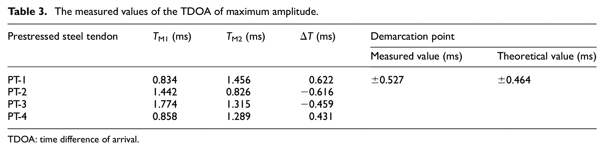
The maximum amplitude waveform of AE signals is the S-wave and the velocity of the S-wave in steel is generally 3230 m/s. Using Equation (6), the theoretical value ΔT14 at demarcation points is 0.464 ms. Similarly, based on Equation (7), the theoretical value ΔT23 is −0.464 ms. Refer to Table 3, for the steel tendon PT-1, the measured TDOA ΔT1 of maximum amplitude is 0.622 ms; for PT-2, the measured TDOA ΔT2 is −0.616 ms; for PT-3, the measured maximum amplitude TDOA ΔT3 is −0.459 ms; for PT-4, the measured TDOA ΔT4 is 0.431 ms. The damaged prestressed steel tendon in prestressed concrete girders can be identified by the value of the maximum amplitude TDOA, see Figure 9. The measured mean values ΔT14 of 0.527 ms and ΔT23 of −0.527 ms are used as the demarcation points to distinguish damaged steel tendons. When the maximum amplitude TDOA for damaged signals meets 0.527 ms < ΔT, PT-1 is damaged; similarly, when ΔT < −0.527 ms, PT-2 is damaged; when −0.527 ms < ΔT < 0, damage occurs in PT-3; when 0 < ΔT < 0.527 ms, damage occurs in PT-4.
The measured values of the TDOA of maximum amplitude.
TDOA: time difference of arrival.
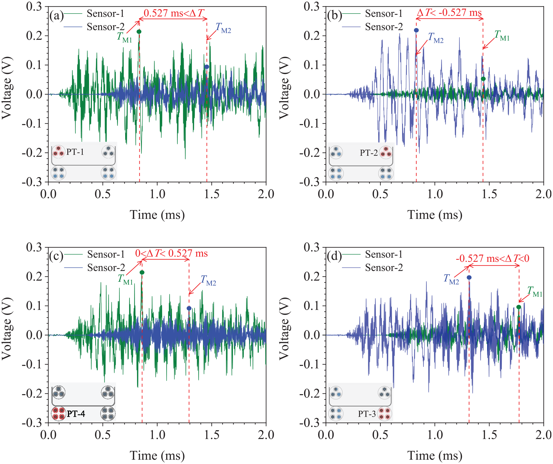
Localization results using the TDOA of maximum amplitude: (a) PT-1, (b) PT-2, (c) PT-4, and (d) PT-3.
The maximum amplitude TDOA of the AE signal for different damaged prestressed steel tendons varies. The damaged prestressed steel tendon can be accurately identified through the maximum amplitude TDOA of damage signals captured with Sensor-1 and Sensor-2.
To summarize, by analyzing the localization results of damaged prestressed steel tendons in prestressed concrete girders, the dual-sensor AE localization method can accurately identify the damaged steel tendon only by the TDOA of the damaged signal. The different waveforms in damage signal propagation, that is, P- and S-waves, have different demarcation point values. In applications, the maximum amplitude TDOA is recommended to identify and localize the damaged steel tendon for the safety of prestressed concrete girder bridges.
Comparison of positioning results for various connection forms
In the previous section, the localization results under rebar welding are analyzed, and the feasibility of the dual-sensor AE localization method is verified. In the following, the localization results based on the maximum amplitude TDOA under four various connection forms are compared to find an appropriate connection form in engineering.
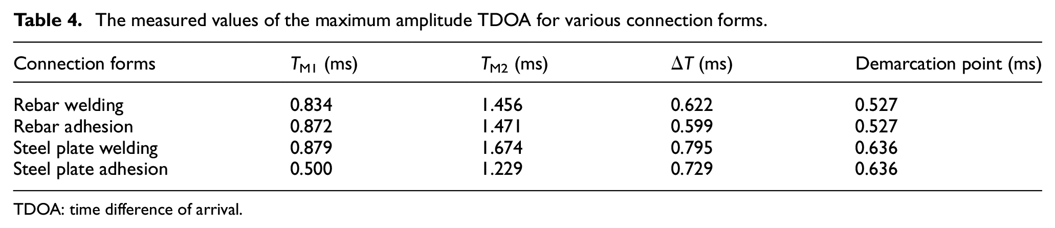
From Table 4, the measured maximum amplitude TDOA of AE signals for the damaged prestressed steel tendon PT-1 under four different connection forms is 0.622 ms (rebar welding), 0.599 ms (rebar adhesion), 0.795 ms (steel plate welding), and 0.729 ms (steel plate adhesion), respectively.
The measured values of the maximum amplitude TDOA for various connection forms.
TDOA: time difference of arrival.
Figure 10 shows the localization results based on the maximum amplitude TDOA of AE signals for different connection forms when damage occurs in the prestressed steel tendon PT-1. Whether the waveguide rod is rebar or steel plate, and whether the fixing method is welding or adhesion, all four connection forms could be used to localize the damaged prestressed steel tendon by the maximum amplitude TDOA of the damage signal. The maximum amplitude TDOA measured using steel plate waveguide rods is slightly larger than that of rebar waveguide rods because the AE wave propagation velocity inside the steel plate is smaller than the propagation velocity inside the rebar. Fixing methods such as welding or adhesion will not change the measured value of the demarcation point. The localization results of the proposed method are not affected by the type of waveguide rod and its fixing method. However, considering the spatial position of anchorages in the real girder, the rebar waveguide rod is recommended in engineering.
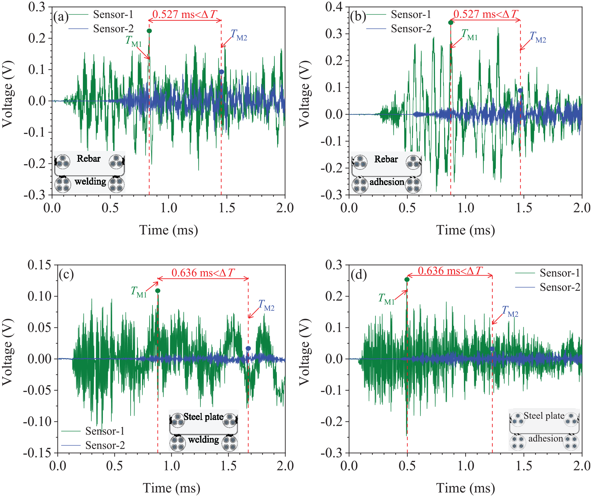
Localization results for various connection forms: (a) rebar welding, (b) rebar adhesion, (c) steel plate welding, and (d) steel plate adhesion.
Case study: application in a full-scale girder
In previous sections, the feasibility of the dual-sensor AE localization method is verified without considering the effect of concrete and other factors. In this section, the rebar waveguide rod is improved based on the spatial position of anchorages in a post-tensioned prestressed hollow slab. The dual-sensor AE localization test is carried out in this full-scale girder, and the localization effectiveness is analyzed to demonstrate the practicality of this localization method in real girders.
Full-scale girder and improved rebar waveguide rod
A post-tensioned prestressed hollow slab with unsealed anchorages was selected for the dual-sensor AE localization test. The full-scale girder was a skewed girder with a length of 16 m, a width of 1240 mm, and a height of 850 mm, as shown in Figure 11. The design grade of concrete used in this full-scale girder was C50, HRB400 rebar was used as ordinary rebar, and prestressed steel tendons were low-relaxation, high-strength strands with a tensile strength of 1860 MPa and a nominal diameter of 15.20 mm. The prestressed ducts were pre-installed circular metal bellows, and the anchorages were YM15-4 and YM15-3 circular anchorages.
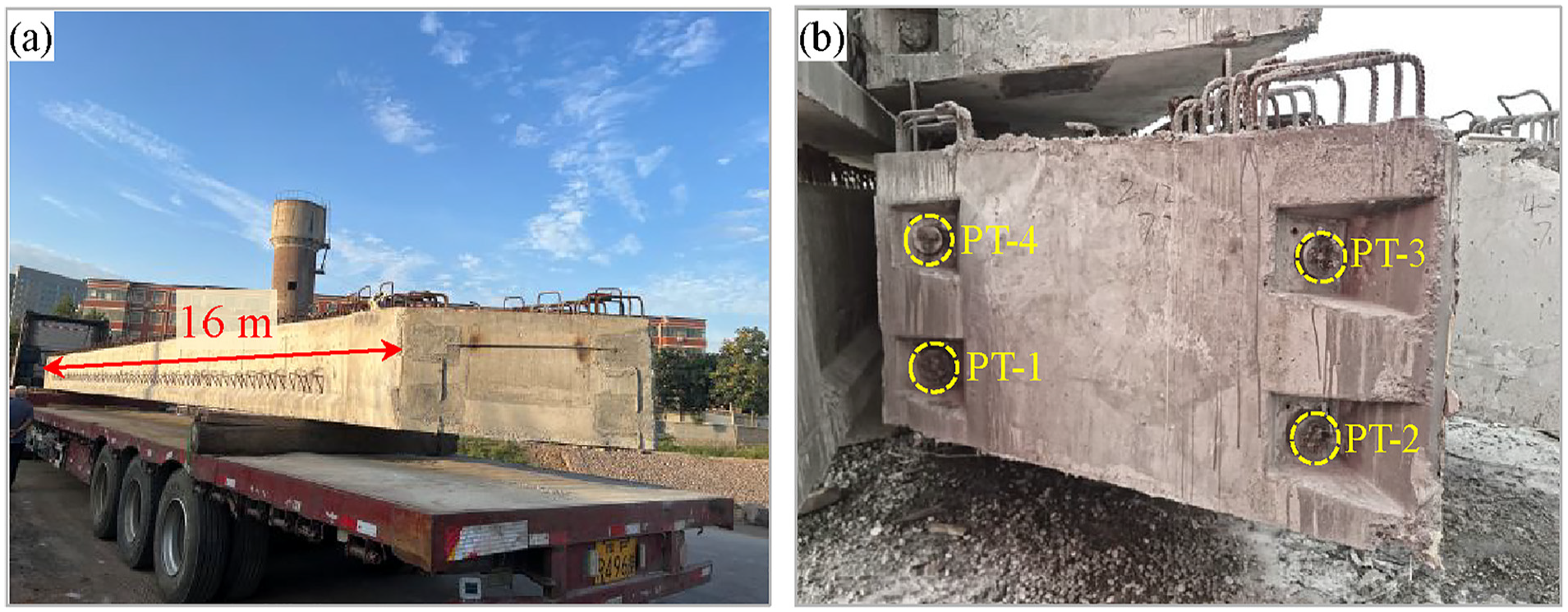
Post-tensioned prestressed hollow slab: (a) overview and (b) the end of the girder.
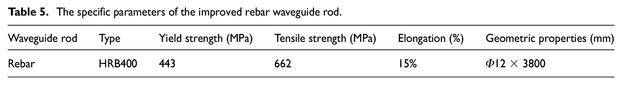
The rebar waveguide rod was improved according to the spatial position of anchorages in this post-tensioned prestressed hollow slab, as shown in Figure 12. The improved rebar waveguide bar adopted HRB400 hot-rolled ribbed rebar, and its specific parameters are shown in Table 5. To facilitate the inspection, maintenance, and replacement of AE sensors during bridge service, the connection direction of the rebar waveguide rod was changed, and prestressed steel tendons were renumbered. The improved rebar waveguide rod was connected only to anchorages to minimize concrete interference on damage signals. The waveguide rods were easily and quickly installed before the final anchorage sealing of the full-scale girder. Although installing the waveguide rods added a small amount of work, this method could reduce long-term monitoring costs, improve monitoring efficiency, and reduce the operation and maintenance costs of the in-service bridge as a whole.
Improved rebar waveguide rod: (a) details on the left, (b) overview of the rod, and (c) details on the right.
The specific parameters of the improved rebar waveguide rod.
Experimental scheme
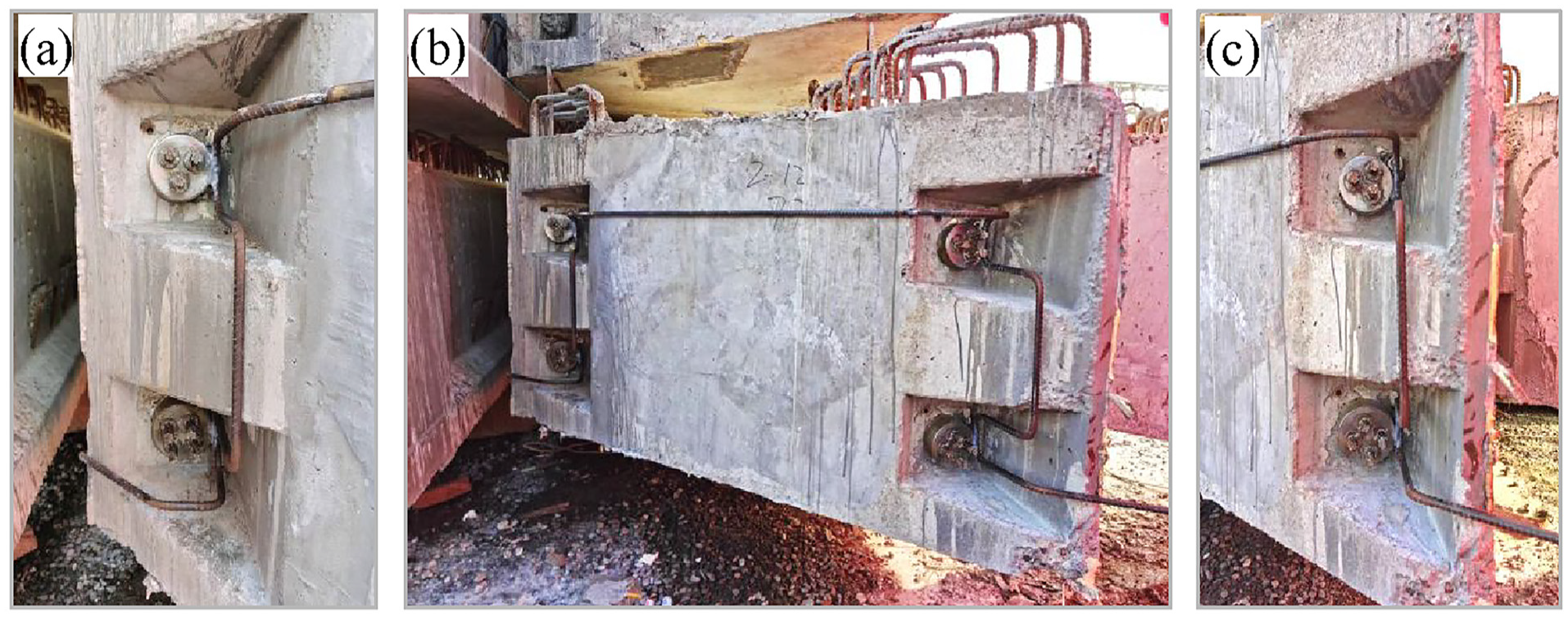
The localization test of damaged prestressed steel tendons in the real girder was conducted under the test conditions of rebar welding before sealing, rebar adhesion before sealing, and rebar welding after sealing, as shown in Figure 13. During the testing, two AE sensors, Model RS-2A, were mounted to the rebar waveguide rod surface, located 2 cm below prestressed steel tendons PT-1 and PT-2, respectively. The excitation signals were generated by hammering the steel tendon to simulate damaged signals,40,41 and the hammering point was located at the opposite end of the girder (without the waveguide rod). The hammering method is a commonly used excitation method. The hammer head used in this experiment is made of steel, weighing about 0.9 kg, having a length of 125 mm and a diameter of 35 mm for the flat head. The handle is made of wood, and it has a length of 320 mm. During the test, the hemispherical hammer head was used for excitation. All four prestressed steel tendons were hammered sequentially from PT-1 to PT-4, each being hammered three times, as shown in Figure 14. Hammering or breaking pencil leads on different strands within the same tendon does not affect the positioning results. Thus, an arbitrary strand was selected for hammering. AE monitoring system and time parameters were consistent with section “AE monitoring system.”
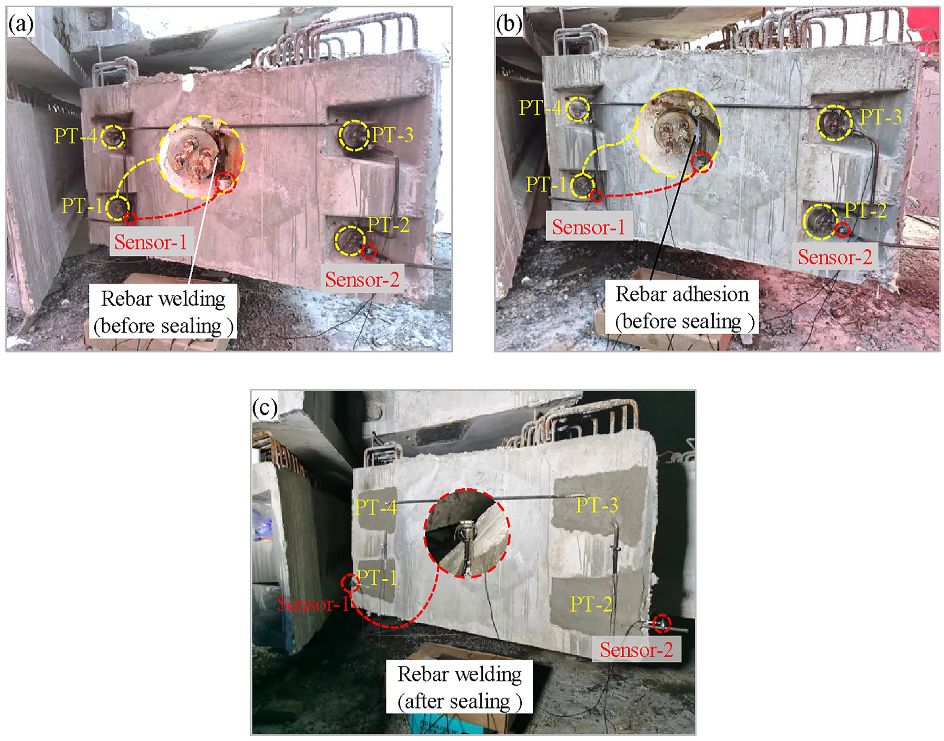
Test conditions: (a) rebar welding before sealing, (b) rebar adhesion before sealing, and (c) rebar welding after sealing.
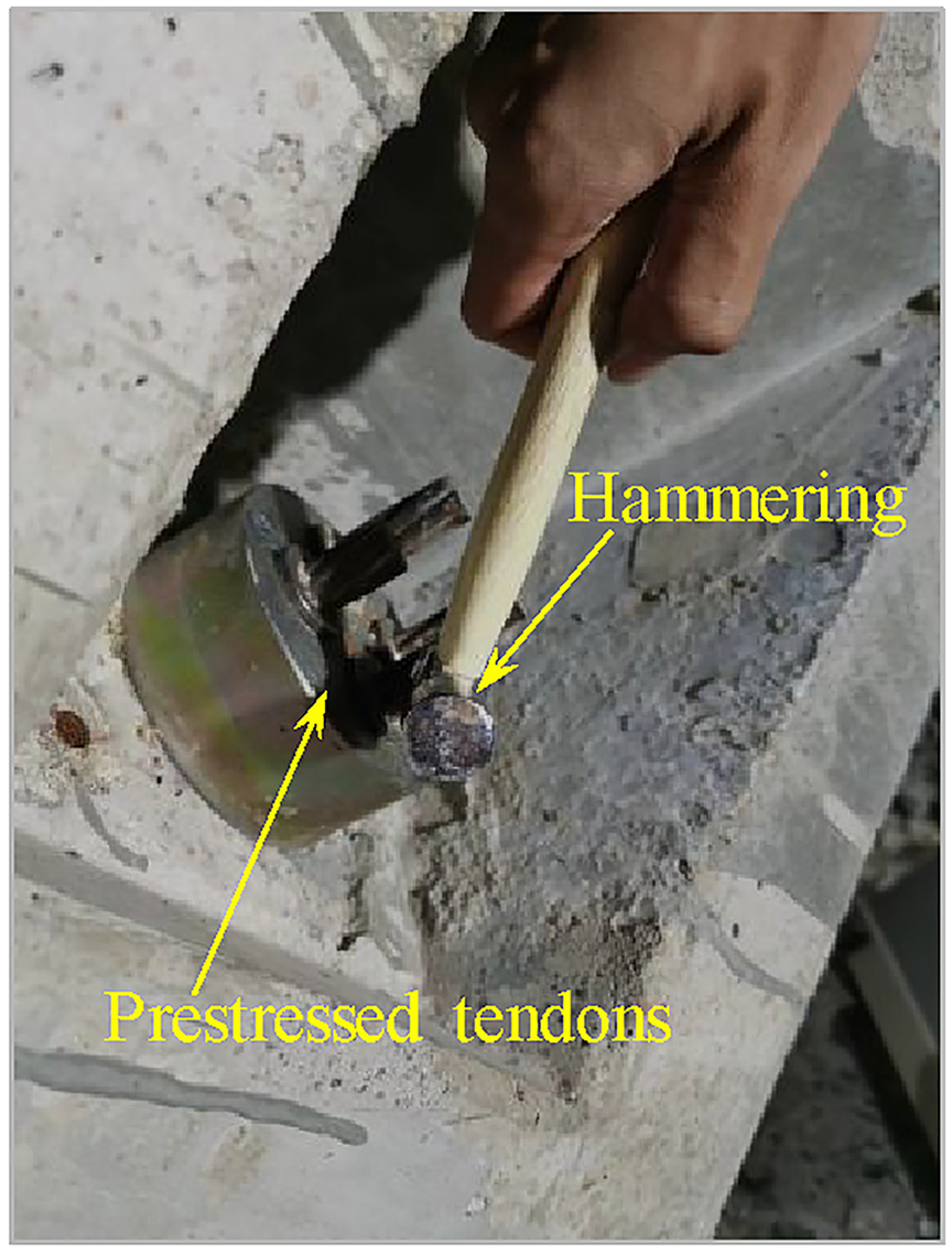
AE source excitation signals: hammering.
Localization effectiveness in the real girder
The following is an example of rebar welding before sealing, and the localization effectiveness in the real girder is analyzed to prove the practicality of this localization method in applications.
Based on section “Localization with TDOA of maximum amplitude,” the maximum amplitude TDOA is suggested for the identification and localization of damaged steel tendons. 39 In the improved rebar waveguide rod, the d2 and d3 equal 1440 mm, and the d1 is 920 mm. According to Equations (6) and (7), the theoretical values ΔT14 and ΔT23 of the demarcation point to distinguish the damaged prestressed steel tendon are 0.731 and −0.731 ms, respectively. Shown in Table 6, the measured maximum amplitude TDOA ΔT1, ΔT2, ΔT3, and ΔT4 are 1.004, −0.996, −0.532, and 0.578 ms for prestressed steel tendons PT-1, PT-2, PT-3, and PT-4, respectively. To distinguish the damaged prestressed steel tendons, the measured mean values ΔT14 of 0.791 ms and ΔT23 of −0.791 ms are taken as the demarcation points, as shown in Figure 15. When the maximum amplitude TDOA ΔT of damaged signals meets 0.791 ms < ΔT, PT-1 is damaged; similarly, when ΔT < −0.791 ms, PT-2 is damaged; damage occurs in PT-3, when −0.791 ms < ΔT < 0; PT-4 is damaged, when 0 < ΔT < 0.791 ms.
The measured values of the maximum amplitude TDOA in the real girder.
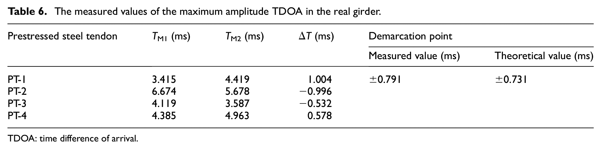
TDOA: time difference of arrival.
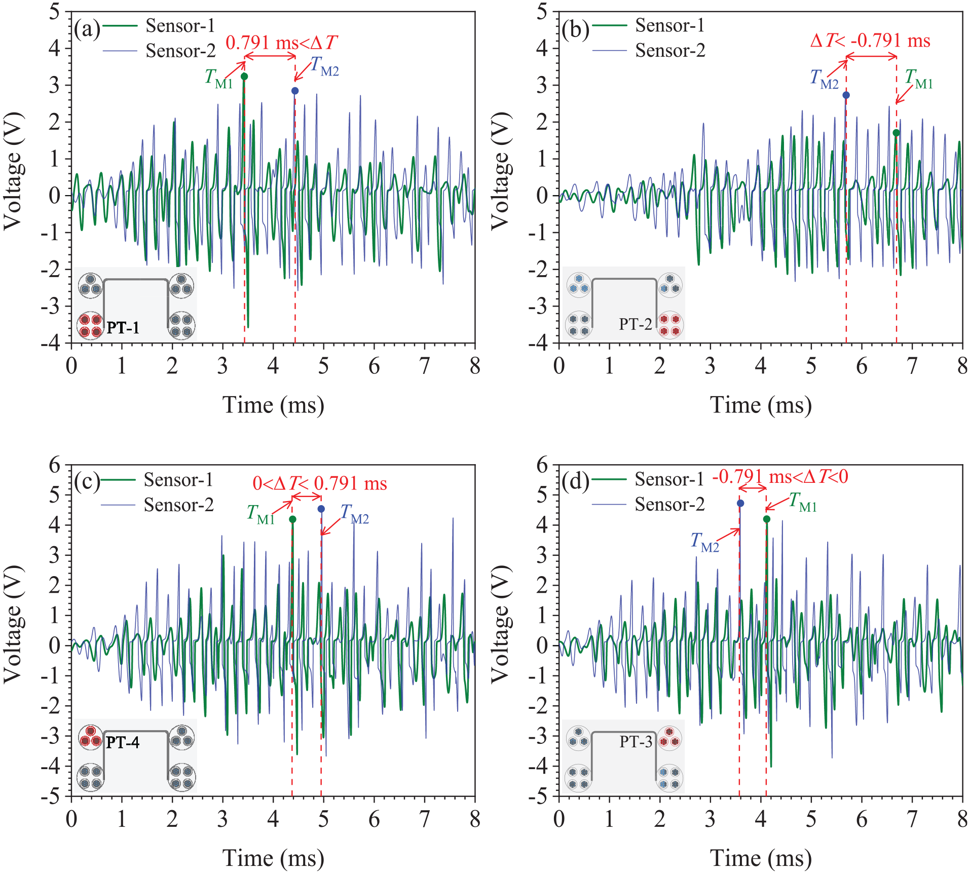
Localization effectiveness in the real girder: (a) PT-1, (b) PT-2, (c) PT-4, and (d) PT-3.
In short, the prestressed steel tendons are preconnected using the improved rebar waveguide rod, and the maximum amplitude TDOA of damaged signals can accurately identify the damaged steel tendon in the real girder. The girder concrete and non-prestressed steel reinforcement will not affect the localization results.
Comparison of localization effectiveness before and after anchorage sealing
A comparison is made in this section of the localization effectiveness under rebar welding before sealing, rebar adhesion before sealing, and rebar welding after sealing to evaluate the influence of anchorage sealing on localization effectiveness.
As shown in Table 7, the maximum amplitude TDOA measured values in this real girder under different connection forms are 1.004 ms (rebar welding before sealing), 0.968 ms (rebar adhesion before sealing), and 1.037 ms (rebar welding after sealing), respectively. Figure 16 shows the localization effectiveness for three different connection forms before and after anchorage sealing in the real girder. The three connection forms have the same demarcation point because they use the same rebar waveguide rod to preconnect prestressed steel tendons. The value of the demarcation point of the improved rebar waveguide rod is greater than that of the previous rebar waveguide rod. After improving the waveguide rods according to the cross-section form, the value of the demarcation point should be recalculated and measured. And the anchorage sealing will not affect the localization effectiveness of the dual-sensor AE localization method.
The measured values of the maximum amplitude TDOA before and after anchorage sealing.
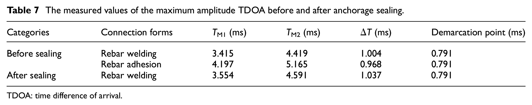
TDOA: time difference of arrival.
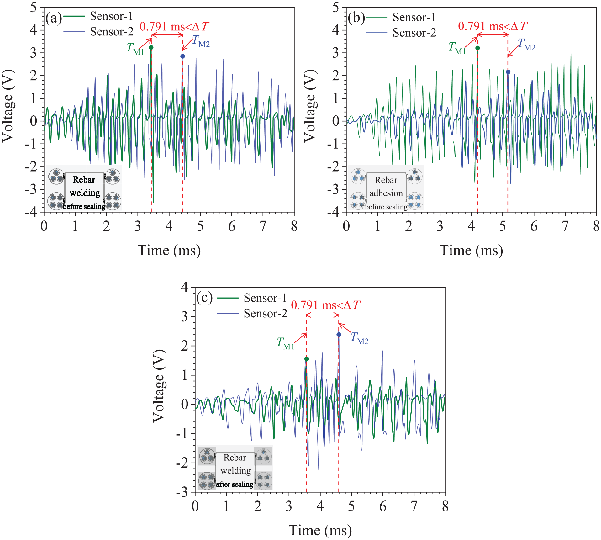
Localization effectiveness before and after anchorage sealing in the real girder: (a) rebar welding before sealing,(b) rebar adhesion before sealing, and (c) rebar welding after sealing.
Conclusion
To reduce the long-term monitoring costs of in-service bridges, a dual-sensor AE localization method using the waveguide rod is presented in this study to localize the damaged steel tendon in prestressed concrete girders. The waveguide rods were easily and quickly installed before the final anchorage sealing of the full-scale girder. Independent of the effects of ambient noise, this localization method can identify the damaged steel tendon using the TDOA of the damage signal captured with only two sensors arranged on the waveguide rod. Following is a summary of the main findings.
The values of demarcation points corresponding to AE waves’ different modes in the damage signal differ. The theoretical and measured values of the demarcation point for the head wave TDOA under rebar welding are ±0.255 and ±0.292, respectively. To the maximum amplitude TDOA, the theoretical and measured values are ±0.464 and ±0.527, respectively. The measured values of the demarcation points approximate the theoretical values and the measurement errors are small.
The TDOA of the damage signal calculated from the maximum amplitude and the head wave enables the localization of the damaged steel tendon. In applications, the maximum amplitude TDOA is recommended to localize the damaged steel tendon to ensure the safety of bridges.
The type of waveguide rods and their fixing method will not affect the localization results of the proposed method. The measured values of the demarcation points depend only on the type of waveguide rods. Considering the spatial position of anchorages in the real girder, the rebar waveguide rod is recommended in engineering.
The practicality of the dual-sensor AE localization method has been verified by analyzing the localization effectiveness in the real girder. Factors such as anchorage sealing, girder concrete, and non-prestressed reinforcement do not affect the localization effectiveness of the proposed method.
The values of the demarcation points of the rebar waveguide rods before and after the improvement are different. When the waveguide rods are modified corresponding to the cross-sectional form of prestressed concrete girder bridges, the value of the demarcation point should be recalculated and re-measured.
The PLB and hammering were used in this study to generate excitation to simulate damaged prestressed steel tendons. The characteristics of these artificially excited signals are similar to the characteristics of the damage signals of real bridge steel tendons and have better consistency and repeatability. Many scholars have used them to simulate the damage signals.
This localization method could effectively reduce the long-term health monitoring cost of in-service bridges and has a broad application prospect. The practicality of this localization method will be further verified with more practical applications in the field. Compared to wire breakage, AE signals generated by prestress loss and corrosion are low in amplitude and easily drowned out by ambient noise, making it difficult to monitor such damage with the localization method proposed in this paper. In subsequent studies, the authors will aim to develop a method to quantify the residual prestress or corrosion degree in steel tendons by combining other detection means (e.g., ultrasonic guided waves, etc.) based on the proposed localization method.
It is worth noting that this localization method has been successfully applied to the post-tensioned prestressed hollow slab girder. The waveguide rod should be improved according to the specific structural form of the bridge. Theoretically, this localization method is also suitable for box girder bridges, but it has not yet been validated on prestressed concrete girder bridges with other cross-sectional forms.
Footnotes
Appendix
Explanation of acronyms.
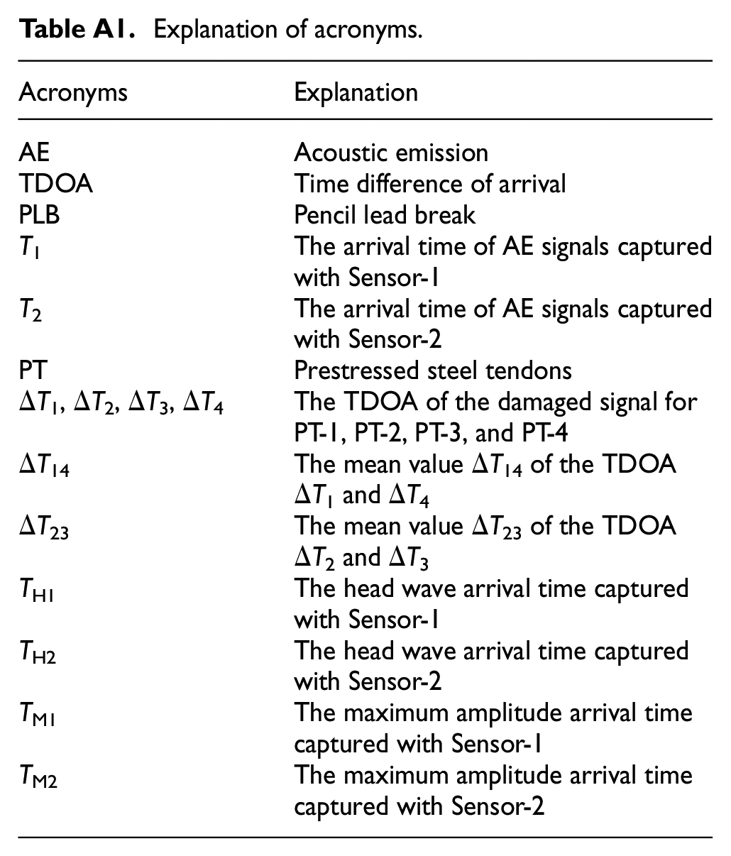
| Acronyms | Explanation |
|---|---|
| AE | Acoustic emission |
| TDOA | Time difference of arrival |
| PLB | Pencil lead break |
| T 1 | The arrival time of AE signals capturedwith Sensor-1 |
| T 2 | The arrival time of AE signals capturedwith Sensor-2 |
| PT | Prestressed steel tendons |
| ΔT1, ΔT2, ΔT3, ΔT4 | The TDOA of the damaged signal forPT-1, PT-2, PT-3, and PT-4 |
| ΔT14 | The mean value ΔT14 of the TDOAΔT1 and ΔT4 |
| ΔT23 | The mean value ΔT23 of the TDOAΔT2 and ΔT3 |
| T H1 | The head wave arrival time capturedwith Sensor-1 |
| T H2 | The head wave arrival time captured with Sensor-2 |
| T M1 | The maximum amplitude arrival time captured with Sensor-1 |
| T M2 | The maximum amplitude arrival timecaptured with Sensor-2 |
Declaration of conflicting interests
The author(s) declared no potential conflicts of interest with respect to the research, authorship, and/or publication of this article.
Funding
The author(s) disclosed receipt of the following financial support for the research, authorship, and/or publication of this article: The authors are grateful for the financial support from the National Natural Science Foundation of China (52208323), Henan Provincial Science and Technology Research Project (232102320010, 212102310975, 222102 320436), and Zhongyuan Sci-Tech Innovation Leading Talents (254000510019).