
Abstract
This study introduces an innovative sensor system using micro energy harvesters based on micro-electro-mechanical systems (MEMS) integrated with Sacrificial Anode Metal Sheets (SAMS) for monitoring chloride-induced steel corrosion in reinforced concrete (RC) structures. MEMS devices enable real-time structural health monitoring by tracking changes in frequency and amplitude due to vibration-based electrostatic power generation. Among the tested SAMS materials (aluminum, copper, iron, and zinc), Fe demonstrated the highest sensitivity, with consistent frequency drops of 250 Hz under wet and dry conditions, creating it as the most suitable for MEMS integration. Parametric experiments also identified optimal target frequencies for energy harvesting: 300 and 350 Hz for a 20 mm cantilever length, and 150 and 200 Hz for a 30 mm cantilever. This proactive approach enables early detection of corrosion in RC structures, enhancing infrastructure safety and advancing corrosion detection methodologies.
Introduction
Chloride ion conventional monitoring
Appropriate maintenance of chloride-induced corrosion in reinforced concrete (RC) structures is a significant challenge, particularly in coastal and marine environments, where airborne chlorides accelerate steel reinforcement deterioration. This issue is especially urgent in Japan, where aging infrastructure demands costly and frequent repairs. Currently, 30% of bridges are over 50 years old, with this figure projected to reach 55% within the next decade. 1 Tunnels over 50 years old are expected to rise from 22 to 36% in the same period. Chloride-induced corrosion contributes to an annual maintenance cost of approximately 4.5 trillion yen, according to the Ministry of Land, Infrastructure, Transport and Tourism. 2 Traditional inspections, while essential, are labor-intensive and costly and often provide only localized or periodic data, delaying timely interventions. Therefore, continuous monitoring of chloride accumulation is critical to ensure the structural integrity and long-term durability of RC structures in corrosive environments.
Several conventional methods for detecting chloride deposits and steel corrosion have been reported, including the gauze method,3,4 patch exposure test, 5 and wire sensor method,6,7 offering distinct advantages and limitations, respectively. The gauze method is recognized for its simplicity and cost-effectiveness, using basic equipment to measure airborne chloride, and it is therefore well-suited for small-scale monitoring.3,4 In contrast, its limitations include potential inaccuracies due to chloride particle bypassing, which can lead to unreliable data, and challenges in monitoring larger structures. Factors such as material heterogeneity and surface contamination can further affect accuracy. The patch exposure test utilizes a bonded patch specimen on the structure’s surface, giving localized assessments of corrosion conditions and enabling targeted monitoring in specific areas of concern. 5 However, it cannot provide a comprehensive overview of chloride distribution across large structures, limiting its effectiveness for broader applications. On the other hand, the wire sensor method or half-cell potential (HCP) measurement employs sensors directly embedded in RC structures to monitor steel corrosion remotely. The advantage of this method is its ability to collect continuous data, supplying ongoing insights into corrosion activity without frequent manual intervention.6,7 However, the installation process presents challenges, as drilling into the concrete may cause minor damage to the structure, and the higher installation costs make the operation less economical than the other methods such as gauze and patch tests.
Advancements in structural health monitoring (SHM) for RC structures in marine environments require solutions that overcome the limitations of traditional chloride detection methods. Conventional techniques, such as gauze tests and wire sensors, often provide only localized, labor-intensive measurements, which hinder comprehensive, real-time monitoring. These methods can struggle to provide broad and continuous data across large structures, making it difficult to assess the full extent of chloride penetration and corrosion over time. Various SHM techniques have been explored to address these challenges. One widely studied approach is the electro-mechanical impedance (EMI) method, which is effective in detecting early-stage damage in RC members.8–11 This technique is based on changes in electrical impedance caused by structural damage and can provide high sensitivity in localized areas. However, EMI often requires wiring to connect the Lead Zirconate Titanate (PZT) patches to the impedance analyzer for both actuation and sensing and it can be challenging for EMI techniques to differentiate between corrosion damage and other types of structural damage (e.g., cracks, loosening of joints) based solely on impedance changes, limiting the potential for large-scale distributed sensing.
To address these limitations, this study investigates the utilization of Micro-Electro-Mechanical Systems (MEMS) energy harvesting technology for chloride ion environment monitoring. MEMS devices, specifically micro energy harvesters (MEHs), offer a modern solution by integrating compact, battery-free sensors that can be deployed in large numbers. Their flexibility allows for installation in various locations and quantities, enabling precise detection of chloride levels at specific points. This localized detection capability is crucial for identifying vulnerable spots within a structure, allowing for more proactive maintenance and extending the lifespan of RC structures. By integrating MEMS-MEH technology into SHM systems, a more comprehensive and efficient approach to managing chloride-induced corrosion can be achieved, ultimately enhancing critical infrastructure safety, durability, and economic viability.
This study develops a MEMS-based monitoring system using MEH technology to identify chloride-induced corrosion-prone areas in RC structures. Unlike conventional MEMS-based SHM,8–13 which mainly detects mechanical changes with structural behavior of targeted infrastructure such as bridges and buildings, this system integrates sacrificial anode metal sheets (SAMS) into MEMS-MEH devices, enabling both corrosion detection of SAMS and energy harvesting for monitoring of the exposure environment. The novelty lies in using SAMS to track corrosion through frequency shifts while also generating power, making the system self-sustaining by observing the potential of corrosive conditions.
This research establishes a direct link between corrosion status and electrical response from the proposed sensor device, optimizing metal sheet materials for specific environments. The findings will help to define the target frequencies for reliable MEMS-MEH performance in predicting corrosion conditions of RC structures.
MEMS vibrational energy harvester
SHM plays a vital role in evaluating the condition of structures over time by using sensors to measure parameters such as strain, vibration, and temperature. This enables early detection of damage or anomalies, facilitating timely interventions and reducing the risk of structural failure.14–16 SHM improves structural reliability, safety, and longevity while minimizing maintenance costs and optimizing resources. Integrating advanced technologies, especially the Internet of Things (IoT), further enhances SHM by providing the infrastructure to manage extensive sensor networks.17–19 Through IoT, real-time data collection, transmission, and analysis are streamlined, enabling comprehensive and continuous monitoring of critical structures. This integration boosts the effectiveness of SHM systems.
However, a key challenge in IoT-SHM systems is providing a sustainable power source for widespread, long-term operation. Vibrational energy harvesting has emerged as a promising solution by converting ambient vibrations into electrical energy, which can either directly power sensors or charge batteries, thereby reducing the need for frequent battery replacements or wired connections. MEMS with MEH technology has significantly advanced the development of compact, efficient vibrational energy harvesters,20,21 enhancing their practicality for SHM applications. 22
The success of SHM and IoT integration also hinges on the selection of appropriate sensing technologies. MEMS sensors are highly suited for this role, offering a unique combination of advantages including low cost, low power consumption, high sensitivity, and compatibility with mass production. These characteristics make MEMS ideal for embedding within structures to monitor a wide range of parameters unobtrusively. By integrating MEMS sensors within an IoT framework, SHM systems can become more efficient, reliable, and scalable. MEMS-based SHM systems enable engineers and asset managers to make well-informed decisions regarding structural maintenance and repair. This integrated approach has the potential to transform infrastructure management by enhancing safety, operational efficiency, and sustainability.
In the field of MEMS technology, significant progress has been achieved through research on electret vibrational energy harvesters, which are MEHs. These studies have focused on analyzing vibrations influenced by environmental and structural characteristics of bridges, intending to quantify the electrical potential harvested from natural ambient vibrations. One notable advancement is the development of comb-shaped silicon electrets, as shown in Figure 1. Silicon electrets have garnered attention in MEMS applications due to their ability to generate power directly via electrostatic induction current. 23 This process converts mechanical vibrations into electrical energy by leveraging the electrostatic properties of the silicon electrets.24,25 The comb-shaped design maximizes the interaction between the vibrating components and the electret material, thereby enhancing the energy conversion efficiency. 26
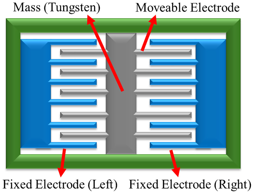
A schematic model of vibrational-based MEMS device. MEMS: micro-electro-mechanical systems.
Given the wide range of frequencies encountered in different environmental conditions, considerable research has been devoted to improving the mechanical performance of MEMS devices. This includes optimizing design parameters to align with the dominant ambient vibration frequencies, enabling the energy harvesters to perform more efficiently across various environments, whether in urban areas with high-frequency vibrations or rural settings with lower-frequency oscillations. 27 Previous studies have demonstrated that the mechanical performance of MEMS energy harvesters is influenced by factors such as the mass of movable components, the quality factor of resonating elements, and the spring constant of the mechanical system. Fine-tuning these parameters can result in more stable and efficient energy harvesting, ensuring compatibility with the vibrational characteristics of specific deployment environments.
Moreover, advancements in material properties and structural design have enhanced the durability and performance of MEMS devices. The use of high-quality silicon materials and innovative fabrication techniques has produced MEMS devices that are not only more efficient but also more resilient to environmental conditions, further improving their reliability and longevity in practical applications.28–30
This article presents a MEMS-based model as the foundation for an innovative sensor designed to monitor chloride ion environments. 31 The device is fabricated from a 300-μm thick device layer of a silicon-on-insulator wafer and incorporates a significant 14.4 g proof mass. Utilizing advanced silicon micromachining techniques, the fabrication process ensures high precision and reliability in designing the sensor.
A major advantage of this MEMS device is its ability to generate over 110 μWRMS of (root-mean-square) power with an acceleration of only 0.003 GRMS (G: the acceleration of gravity), showcasing its efficiency in energy harvesting even in low-vibration environments. 31 In a controlled charging experiment, the device successfully accumulated and stored 4.8 mJ of energy in a 44-μF capacitor over 90 min, using an acceleration waveform measured from a viaduct. 32 This capability to harness ambient vibrations underscores the device’s potential for autonomous operation, eliminating the need for external power supplies.
In addition to its functional performance, the MEMS device is comparable in size to a 10 JPY coin (23 × 23 mm) and offers multiple advantages as presented in Figure 2. First, the reduced size lowers material costs by minimizing packaging requirements and enables cost-effective mass production, thereby increasing the sensor’s affordability. Second, the compact nature of the device enhances its versatility, allowing it to be easily installed in various locations, including confined or hard-to-reach areas. This makes the sensor ideal for monitoring infrastructure such as bridges, buildings, and other critical structures, where it can be strategically positioned to monitor environmental factors like chloride ion concentration, essential for assessing corrosion risks.
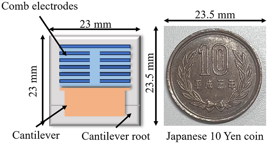
A model of the applied vibration-based MEH device (reproduced from [31]). MEH: micro energy harvester.
The sensor employs comb-shaped silicon electrets to convert mechanical vibrations into electrical energy without the need for batteries. As illustrated in Figure 3, the electret MEMS operates by exploiting changes in the overlapping areas between the movable and fixed comb electrodes when the cantilever vibrates out of plane. 32 These variations in overlapping areas cause changes in the capacitance between the comb electrodes, which in turn alter the electric field within the device. The fluctuating electric field drives the movement of free electrons in the fixed comb electrodes, generating electric currents. These currents can be harnessed for energy generation or to provide real-time data on vibrational behavior of the cantilever. The efficiency of this energy conversion process is dependent on the precision of the MEMS design, the material properties of the comb electrodes, and the characteristics of the ambient vibrations. This ability to efficiently convert mechanical vibrations into electrical energy provide highly valuable for applications such as energy harvesting and SHM into MEMS devices.
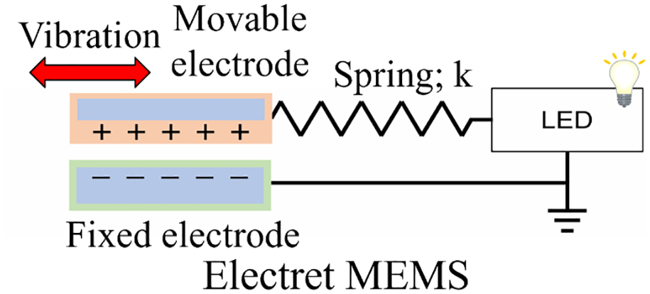
Electret MEMS vibration power generation device. MEMS: micro-electro-mechanical systems.
MEMS sensor design to monitor corrosion
The design of MEMS devices has already been successfully implemented in practical applications, demonstrating their effectiveness in real-world conditions. Studies have shown that the vibrational MEH responds to shifts in modal frequency and amplitude changes in the target structure, 33 highlighting its potential for continuous and long-term SHM. This capability positions MEMS-MEH devices as a valuable complement to traditional bridge monitoring systems.
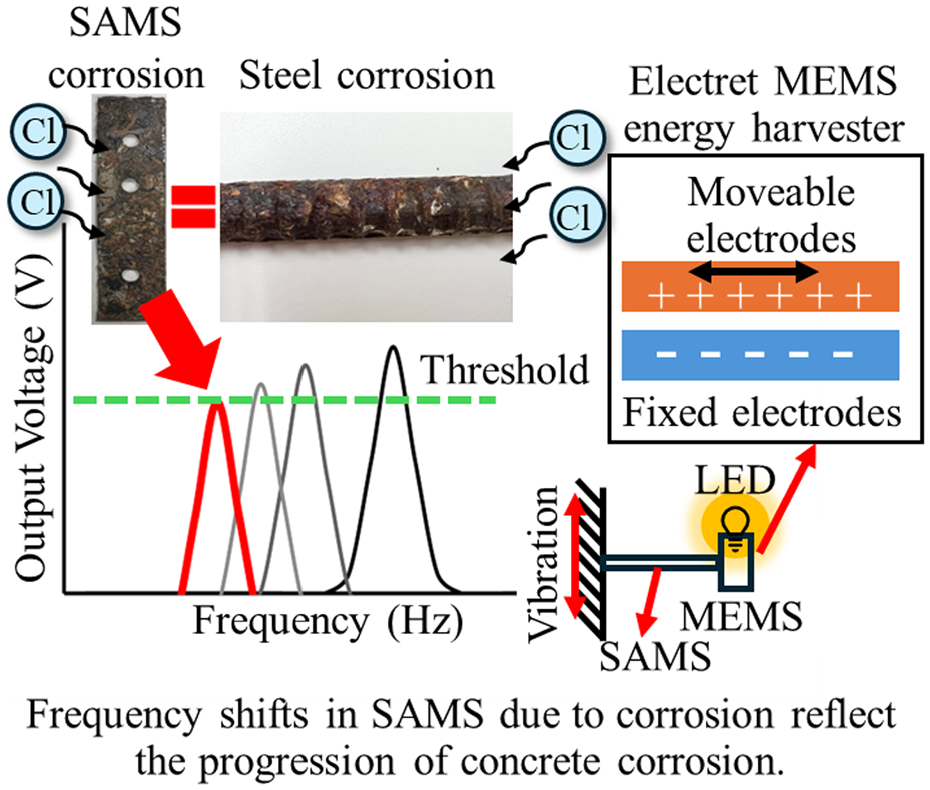
Corrosion affects how metal plates vibrate, enabling damage detection. A previous study used ultrasonic guided waves to analyze how corrosion alters vibration patterns in steel plates, demonstrating that specific frequency shifts can indicate structural damage. 34 Building on these findings, this study integrates SAMS into MEMS devices for corrosion monitoring in chloride-rich environments. SAMS are selected because their dominant frequency changes as they corrode, allowing real-time tracking of corrosion risks. SAMS provide both predictable corrosion behavior and mechanical stability, making them ideal for integration into MEMS energy harvesters. By leveraging these properties, SAMS improves corrosion detection while supporting the dual functionality of MEMS-MEH systems. Figure 4 illustrates the integration of SAMS into MEMS devices for structural corrosion monitoring.
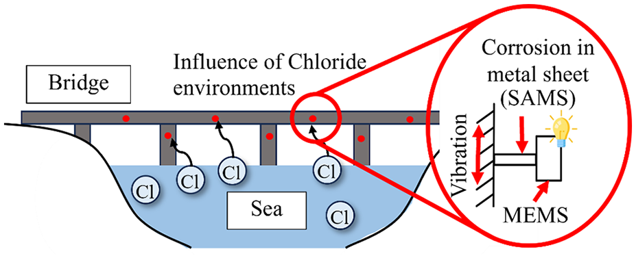
Application of SAMS integrated into MEMS device to monitor corrosion in structures. SAMS: sacrificial anode metal sheets; MEMS: micro-electro-mechanical systems.
Chloride ions, particularly from coastal or seawater sources, unpredictably accelerate steel corrosion in RC structures. The MEMS sensors detect vibrations from the corroding SAMS, and frequency degradation serves as an indicator of corrosion progression, which in turn affects the energy harvesting efficiency from MEMS-MEH device. These MEMS sensors not only monitor corrosion but also serve as energy harvesters, converting environmental vibrations into usable energy, eliminating the need for external batteries. However, maintaining consistent vibration frequencies is essential for ensuring a stable energy output.
The monitoring system is connected to a circuit with resistance components, while Light-Emitting Diodes (LEDs) indicate voltage changes, signaling corrosion when SAMS resonance frequencies decrease. This LED signal provides a visual indicator of corrosion, aiding in timely assessment. Furthermore, the harvested energy powers wireless transmission modules, enabling real-time monitoring of chloride concentration and the associated risk of corrosion. This IoT-enabled feature allows for remote monitoring and proactive maintenance, enhancing the safety and longevity of infrastructure.
When the generated electric power reaches a preset threshold, MEMS sensor activates LED light flashing, indicating corrosive conditions. As the frequency of the corroding SAMS decreases, the frequency response of the electret MEMS changes, leading to variations in the generated current. The electret MEMS, attached to the tip of the corroding SAMS, increases power output as the SAMS’s frequency approaches the designed target frequency. This behavior enables clear detection of SAMS degradation by monitoring changes in generated current, visualized through LED indicators. Figure 5 depicts this process, where the LED lights up as corrosion advances, providing a clear visual cue for corrosion assessment.
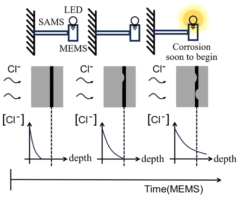
Model of the relationship between MEMS-SAMS with MEH system and corrosion in concrete. MEMS: micro-electro-mechanical systems; SAMS: sacrificial anode metal sheets; MEH: micro energy harvester.
This study highlights the importance of identifying the optimal target frequencies by examining the relationship between cantilever length, material properties, and energy harvester mode. Tuning the system to the optimal target frequency ensures maximum energy harvesting efficiency and precise corrosion monitoring. As the SAMS frequency decreases, indicating advancing corrosion, the harvested energy powers an LED, providing a visual signal that alerts users to the structural health condition. This technical approach establishes an early warning system, helping to safeguard RC structures from chloride-induced corrosion by enhancing durability and safety.
This approach emphasizes the need for maintaining stable vibrational frequencies to guarantee consistent energy generation and timely corrosion detection. Implementing the technical concept as a sensor helps to protect the structural integrity of RC structures, offering an early warning system that enhances both safety and durability in environments vulnerable to chloride-induced corrosion (Figure 6).
Application of SAMS integrated into MEMS device to monitor corrosion in structures. MEMS: micro-electro-mechanical systems; SAMS: sacrificial anode metal sheets.
Materials and methods
Materials
Four types of metals were considered to investigate the corrosion and vibration behavior of metal plates: aluminum (Al), copper (Cu), iron (Fe), and zinc (Zn). These metals were selected due to their distinct physical, mechanical, and electrochemical properties, making them suitable for studying varying corrosion resistance and vibrational characteristics. Al was chosen for its high corrosion resistance and lightweight properties, Cu for its excellent conductivity and moderate corrosion resistance, Fe for its susceptibility to corrosion and widespread industrial use, and zinc for its sacrificial behavior in corrosion protection systems. The samples are 12 × 50 × 0.6 mm sized, with the drilling of three holes of 3 mm diameter to implement vibration measurement distances with lengths of 20 and 30 mm, respectively, as demonstrated in Figure 7.
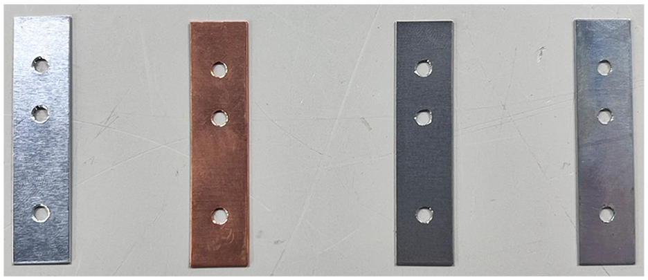
Four types of metal sheets: Al, Cu, Fe, and Zn, from left to right, respectively. Al: aluminum; Cu: copper; Fe: iron; Zn: zinc.
Eight distinct conditions were examined to investigate the effects of environmental exposure on metal sheets, as summarized in Table 1. This study employs a systematic sample naming convention to clearly identify the different exposure scenarios. The abbreviations are structured to represent a combination of temperature, solution type, and exposure conditions. Namely, 20 represents 20°C and 40 for 40°C. N refers to the 3% sodium chloride (NaCl) solution, and H indicates deionized water. The exposure conditions are denoted by D for wet and dry condition and S for full submersion. For instance, a sample exposed to 3% NaCl solution at 20°C under wet and dry condition would be labeled as 20ND, whereas a sample submerged in deionized water at 40°C would be abbreviated as 40HS. This naming convention allows straightforward identification of exposure conditions for each experimental case throughout the study.
Environmental scenarios for exposure conditions.
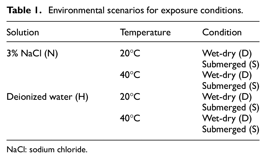
NaCl: sodium chloride.
To simulate the environmental impact in real situations on metal specimens, two types of solutions were used, deionized water and 3% NaCl, to represent different chloride concentrations. The metal sheets were subjected to either wet-dry cycles or full submersion to replicate common environmental conditions. The experiments were conducted under tightly controlled settings, with temperatures maintained at either 20 or 40°C and humidity held at 95% to accelerate corrosion processes. 35 Separate environmental chambers were used to control the temperature for the 20 and 40°C conditions. Each chamber was calibrated to maintain consistent temperature and humidity levels, ensuring that the exposure environments remained stable and uniform throughout the study. For each experimental condition, three specimens of each metal type were used, resulting in a total of 96 metal sheets (eight conditions × four metals × three replicates). Using multiple specimens for each condition ensures the accuracy and reliability of the results by minimizing the effects of variability and enabling statistical analysis of the data. Through detailed analysis of data collected from these carefully controlled experiments, this study seeks to enhance the understanding of corrosion mechanisms and improve strategies for monitoring metal degradation across diverse environments.
In the wet and dry condition, each metal sheet was wrapped in a fabric thoroughly soaked with either deionized water or a NaCl solution. This fabric served as a medium to sustain a consistent wet environment on the metal surfaces. The prepared samples were placed in sealed containers to prevent evaporation and ensure continuous exposure, simulating real-world conditions where metal structures undergo intermittent wet and dry cycles. 36 For the fully submerged condition, the metal sheets were entirely immersed in containers filled with either deionized water or NaCl solution. This setup provided continuous exposure of the entire metal surface to the liquid environment, contrasting with the intermittent exposure to the wet and dry condition, as illustrated in Figure 8. This approach aimed to evaluate how constant immersion impacts the corrosion and vibrational behavior of different metals.
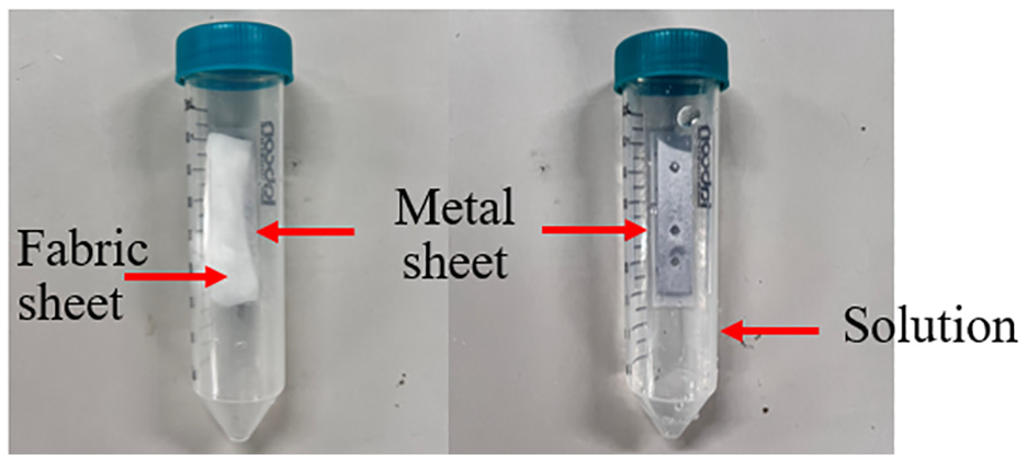
The metal sheets in container with a lid in deionized water or NaCl solution for wet and dry condition (left) and submerged condition (right). NaCl: sodium chloride.
The resonance frequency of metal sheet exposed in each condition was measured every 2 weeks for 24 weeks. Figure 9 represents the measurement equipment and provides an overview of the process for measuring the vibration waveform of the metal sheets. To determine the characteristic peak frequencies, an audio speaker was used to generate mechanical vibrations in the test samples, with frequencies ranging from 20 to 1000 Hz. These vibrations were transmitted at a constant frequency and volume setting for each measurement to ensure consistency. The metal sheets were securely positioned on a stainless-steel apparatus base designed to minimize external disturbances that could affect the readings of the signals. To further enhance measurement accuracy, a rubber mat was placed under the audio speaker to dampen external vibration and prevent unintended noise interference. The accelerometer was carefully attached to the specimens to precisely capture their dynamic response. This setup effectively reduced noise and allowed for consistent tracking of frequency shifts over time, providing reliable data on corrosion-induced changes in the resonance behavior of the metal sheets.
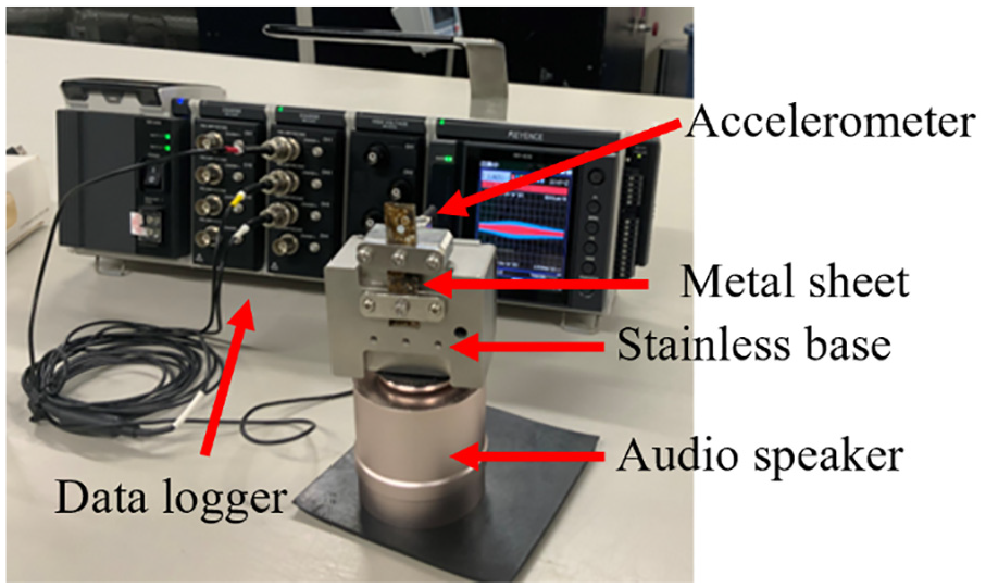
Vibration measuring equipment.
Following the data collection, the frequency spectrum of the detected waveforms is analyzed using fast Fourier transform (FFT). The accelerometer records vibration data as waveforms in the time domain, capturing the dynamic response of the metal sheets. FFT is a mathematical algorithm that transforms these time-domain waveforms into their frequency-domain representation. 37 The FFT algorithm decomposes the complex waveform data into individual sinusoidal components, enabling the detection of dominant frequencies associated with the resonance behavior of the metal sheets. The analysis achieves high-resolution frequency detection, with a sampling rate set at 2000 Hz and a total of 131,072 data points per measurement session. Since the recorded data in each session is approximately 120,000 data points, it remains within the system’s capacity and enough to identify the targeting frequency component in the spectrum. This resolution ensures that even subtle shifts in frequency over time due to corrosion progression are captured effectively.
Figure 10 presents examples of FFT-derived spectra, illustrating the natural frequencies of the metal sheets at distances of 20 and 30 mm, respectively. In each graph, two prominent frequency peaks are observed, representing significant vibration modes for both measurement distances. This analysis provides valuable insights into the vibrational response of the metal sheets, offering a deeper understanding of their structural integrity and potential weaknesses. The second largest amplitude peak was selected because the first peak shows minimal frequency changes, likely due to damping effects. The second peak is more sensitive to frequency shifts, proving it appropriate for detecting corrosion progression.
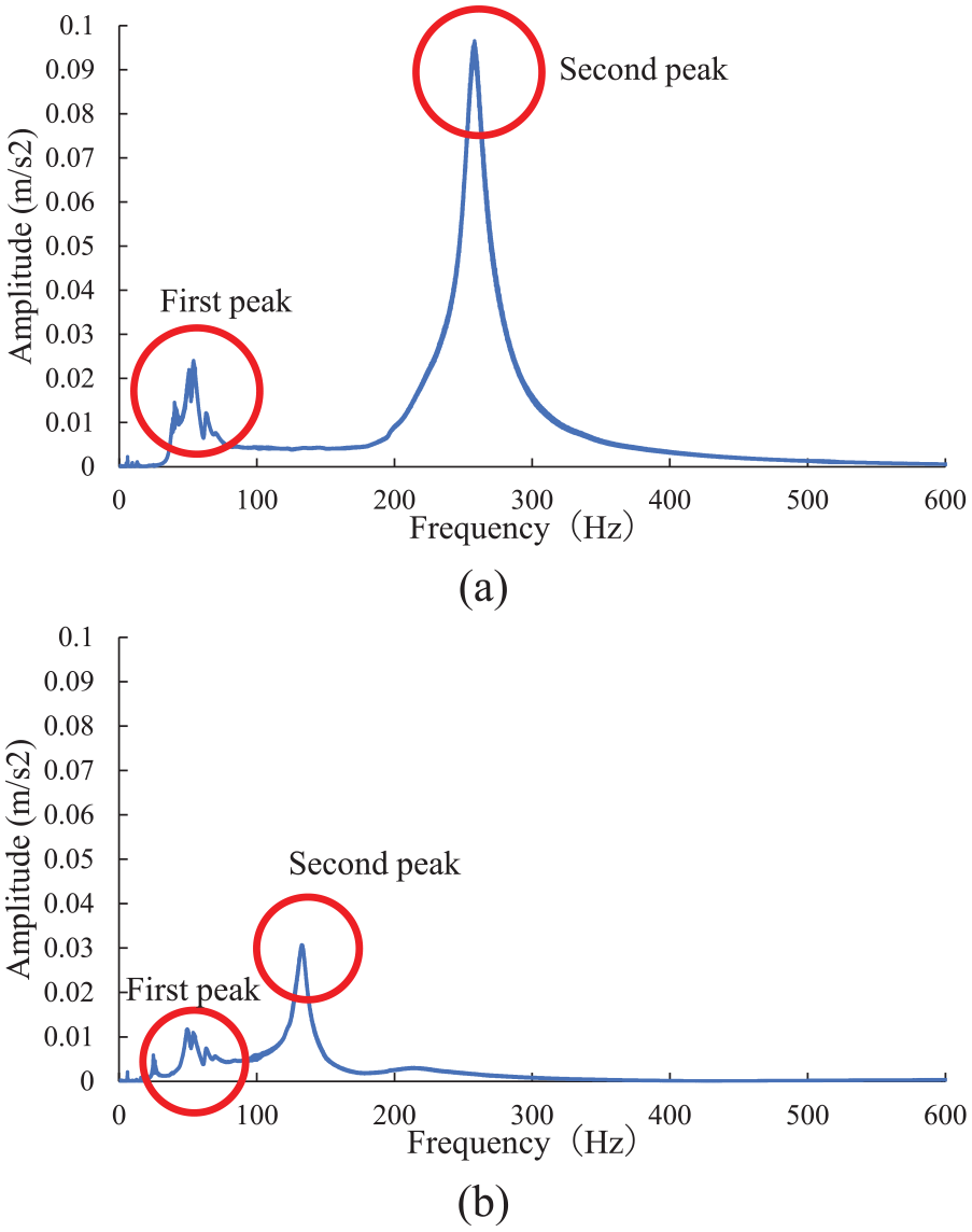
FFT-derived frequency peaks: (a) at 20 mm and(b) at 30 mm. FFT: fast Fourier transform.
Output power calculations
The output power of a vibrational energy harvester, specifically an electrostatic energy harvester, can be modeled using the velocity-damped resonant generator model. 38 This model enables to understand how mechanical vibrations are converted into electrical power. When the movable body of the harvester oscillates at its resonance frequency, the expected root mean square output power P can be calculated as presented in Equations (1) and (2):


where P is the power generation amount in watts (W), m is the mass of the moveable body in kilograms (kg),
Structural and material properties of MEH.
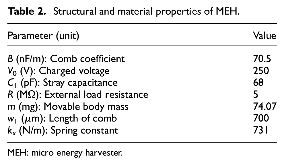
MEH: micro energy harvester.
Experimental results and discussions
Change in resonance frequency
After obtaining the peak frequencies and the amplitude in the FFT spectrum for vibration analysis, identifying the resonance frequency, and the resonance frequency change during the 24-week exposure timeframe is observed. The graphs in Figures 11 and 12 demonstrate the decrease in the resonance frequency over time for metal sheets of Al, Cu, Fe, and Zinc are exposed to 20 and 40°C NaCl in wet and dry condition. The dominant frequency refers to the frequency with the highest peak amplitude in the FFT spectrum each week. This peak indicates the most responsive frequency of the material’s vibration and is used to track resonance changes over time. In all exposure conditions, the initial dominant frequency of Fe is the highest, followed by Zinc, Cu, and AL, respectively. Al and Cu show a constant decline in frequency, whereas the more corrosive metals, Fe and Zinc, generally show greater reductions in frequency.
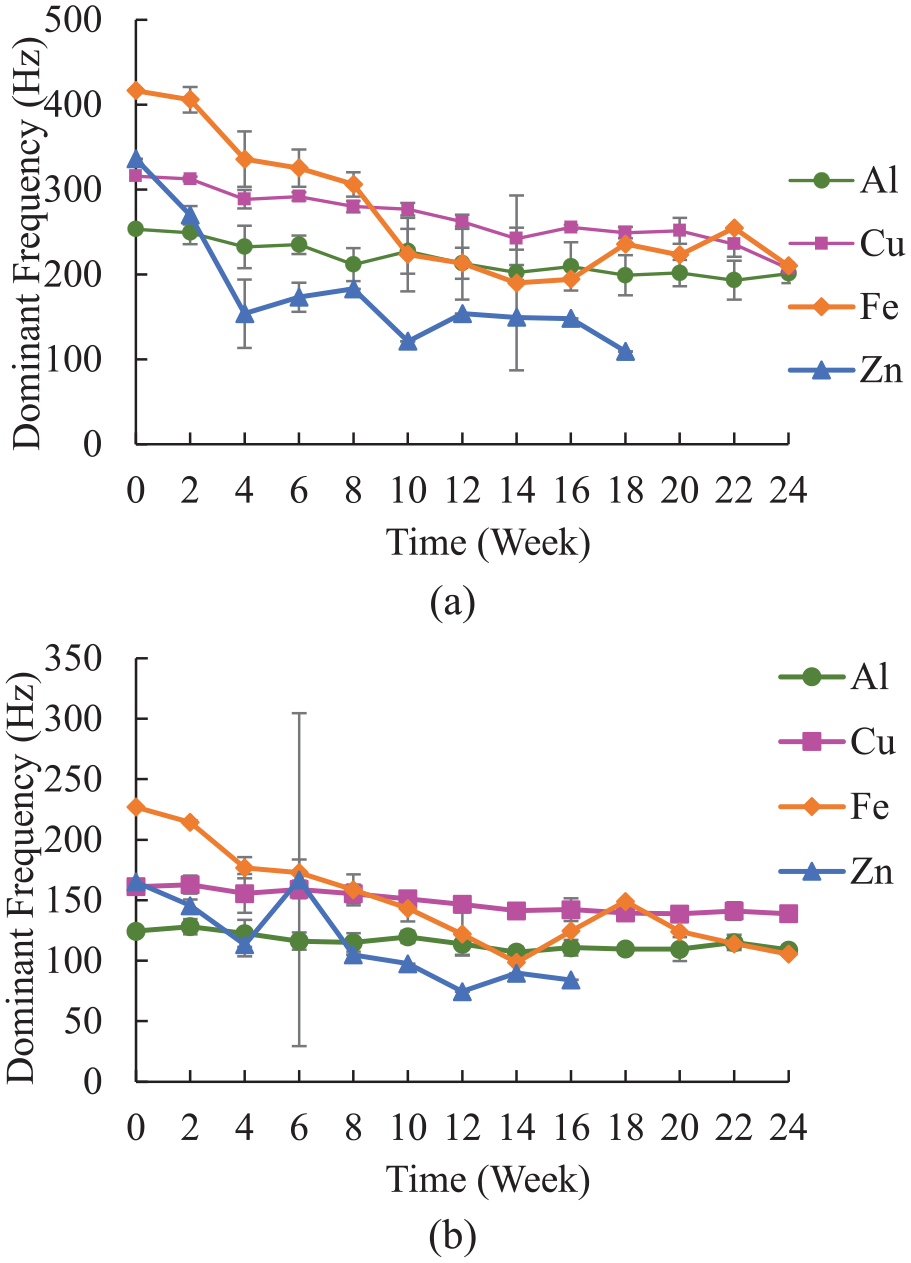
Decreased resonance frequency over time for 20°C NaCl in wet and dry condition: (a) at 20 mm and (b) at 30 mm. NaCl: sodium chloride.
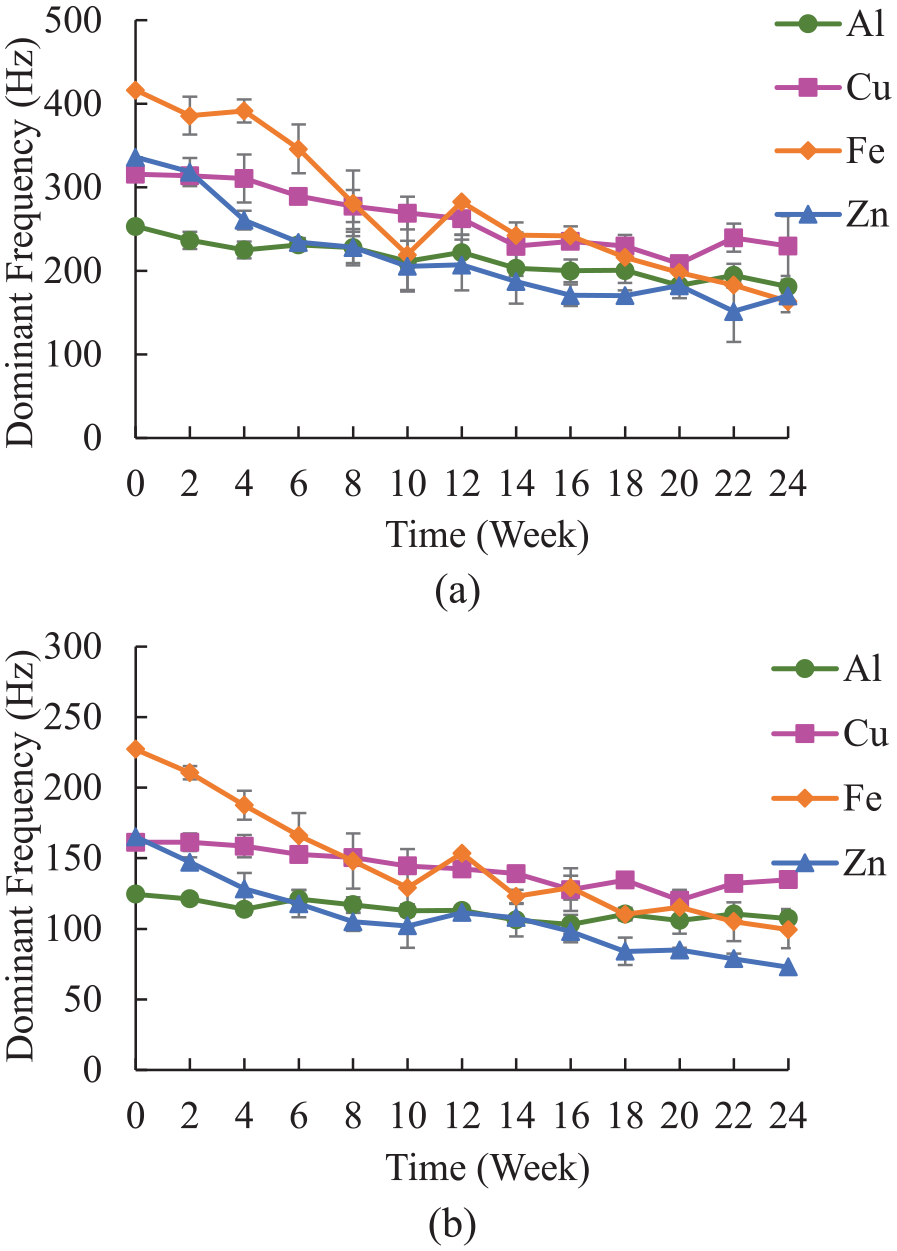
Decreased resonance frequency over time for 40°C NaCl in wet and dry condition: (a) at 20 mm and (b) at 30 mm. NaCl: sodium chloride.
In particular, Figure 11(a) and (b), which illustrate the results under 20°C with NaCl solution in wet and dry condition, it can be observed that Zinc is particularly prone to corrosion, demonstrating a rapid decline in frequency. The cantilever length also significantly influences vibration behavior by altering the mode shape and natural frequency. As shown in Figures 12 (a) and (b), the overall frequency at a 30 mm cantilever length is lower than that at 20 mm, emphasizing that increased length lowers the system’s natural frequency.
The high vibration frequencies in this study come from the material properties of the metal sheets in the MEMS-SAMS system. These thin, small sheets are designed to vibrate at high frequencies, making them very sensitive to corrosion. Even small amounts of corrosion cause noticeable frequency changes, allowing for accurate monitoring. Importantly, MEMS-SAMS focuses only on the vibrations of the metal sheet itself, ensuring it is unaffected by external noise such as wind or traffic. The high starting frequency is an important feature that helps track corrosion clearly and reliably.
To assess the impact of chloride-induced environmental conditions on frequency change, the reduction in resonance frequency from the initial value to the final value for all conditions is analyzed to provide a clear indicator of material degradation over time. The effect of changing temperature from 20 to 40°C is also investigated, revealing that temperature changes did not significantly affect the frequency trends, implying that the frequency change is invariant to temperature. From Figure 13, it is evident that Fe and Zn exhibit a frequency difference of more than 200 Hz at 20 mm and 50 Hz at 30 mm, whereas Al and Cu show smaller differences, less than 200 and 50 Hz, respectively. This indicates that Fe and Zn have a broader range of frequencies compared to Al and Cu in all conditions, suggesting that Fe and Zn are more susceptible to corrosion.
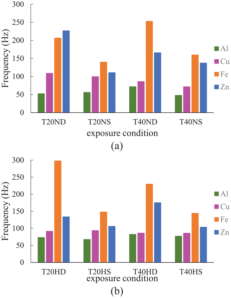
Frequency reduction from initial value to final value measured at 20 mm: (a) NaCl solution and (b) deionized water solution. NaCl: sodium chloride.
The loss cross-section ratio, derived from the reduction in natural frequency, offers valuable insights into the material loss caused by corrosion. This ratio is crucial for selecting materials that perform well in specific environments, as it reveals the correlation between frequency reduction and physical material loss. When comparing the results of Figures 13 and 14, the decrease in frequency from the initial to the final value and the loss of cross-section ratio follow the same trend. For example, when Fe and Zn experience a significant decrease in reduction potential, also exhibit greater cross-sectional area loss, confirming their vulnerability to corrosion. This consistency suggests that Fe and Zn, due to their substantial frequency reduction and corresponding material loss, are more susceptible to corrosion. This consistency further validates the effectiveness of using frequency drop as a corrosion indicator.
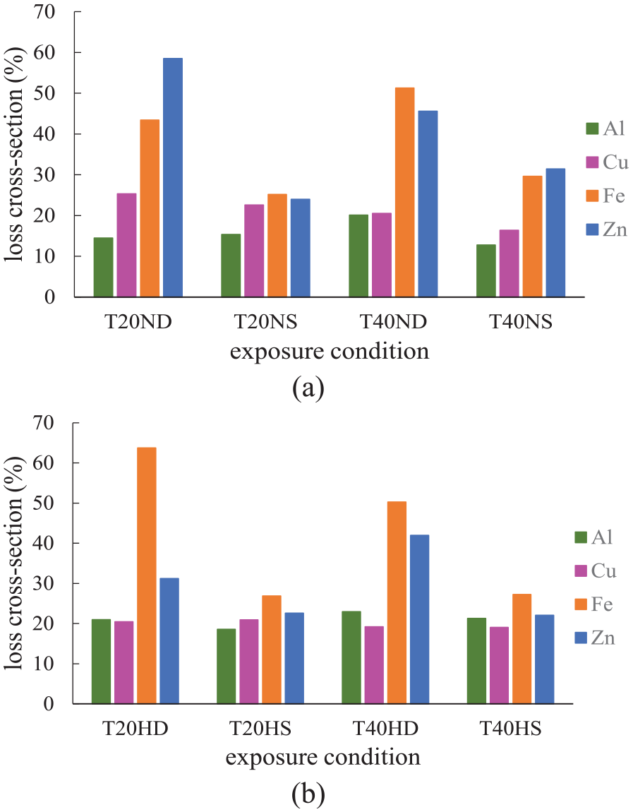
Loss cross-section ratio measured at 20 mm:(a) NaCl solution and (b) deionized water solution.
Even minor corrosion on Fe or Zn surfaces in chloride environments can cause significant frequency shifts in MEMS sensors. This sensitivity is vital for MEMS vibrational energy harvesters, which detect external changes driven by frequency drops. Both Fe and Zn prove to be effective materials for SAMS in MEMS devices, given their distinct responses to corrosion. The correlation between frequency reduction and loss of cross-sectional areas highlights their suitability for monitoring chloride environments, enabling accurate structural health assessment.
To further understand the mechanisms behind metal sheet degradation, X-ray fluorescence (XRF) analysis was conducted (Figure 15) to determine chloride ion concentrations on metal surfaces. Results indicate a higher chloride accumulation on Zn compared to Fe, attributed to the formation of soluble zinc chloride. Fe remains more susceptible to chloride penetration while forming a protective oxide layer. The corrosive impact of chloride ions is amplified in NaCl solutions.43,44 The higher chloride concentrations in NaCl solutions reflect more aggressive corrosion conditions, which are vital for designing monitoring systems in infrastructure.
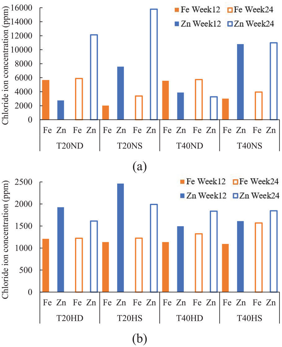
Chloride concentration of Fe and Zn: (a) NaCl solution and (b) deionized water solution. NaCl: sodium chloride; Fe: iron; Zn: zinc.
While XRF detects initial chloride presence, its limitations in identifying subtle changes in Fe oxide composition require laser-induced breakdown spectroscopy (LIBS).45–47 LIBS offers higher precision for identifying Fe oxide phases (FeO, Fe2O3, and Fe3O4) by determining the weight percentages of Fe and oxygen. These values are visualized in ternary plots, which show the progression of oxidation and the dominant corrosion products. The ternary plot in Figure 16 highlights the influence of temperature, water, and chloride ions on the corrosion products forming in the layer of Fe under varying conditions. Exposure to 20°C deionized water (20HD) and 40°C NaCl (40ND) in wet-dry environments leads to elevated levels of FeO, signifying aggressive corrosion. Higher temperatures, such as 40°C, accelerate FeO formation due to rapid initial oxidation in the presence of NaCl, which acts as a catalyst for corrosion by disrupting protective oxide layers. Chloride ions penetrate the oxide films, causing localized pitting and an increase in FeO. Even at lower temperatures (20°C), the corrosion rate remains significant in deionized water, leading to notable FeO formation. Wet-dry cycles further intensify FeO formation by exposing Fe to repeated cycles of oxidation and corrosion, while submerged conditions tend to favor the formation of more stable oxides like Fe2O3 and Fe3O4, indicative of slower, more controlled oxidation processes.48,49 These findings demonstrate the ability to distinguish between severe and mild corrosion environments based on the corrosion products formed, positioning Fe as a suitable candidate for SAMS integration in MEMS devices for monitoring diverse environmental conditions.
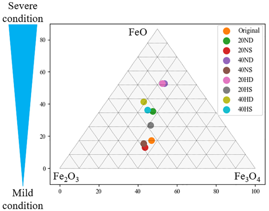
Ternary plot of corrosion products of Fe in all exposure conditions. Fe: iron.
Physical and chemical analyses identified Fe as the optimal SAMS for MEMS integration. Al and Cu showed minimal frequency degradation, making them ineffective for corrosion monitoring. Zn exhibited significant degradation but corroded too rapidly, reducing its long-term stability. Fe was chosen for its balance of durability, stability, and sensitivity to corrosion. LIBS analysis confirmed the formation of protective Fe oxide layers (FeO, Fe2O3, and Fe3O4), which prevent excessive material loss, unlike Zn, which forms soluble corrosion products (ZnCl2). The loss cross-section ratio, based on frequency reduction, indicated controlled degradation, making Fe a reliable corrosion indicator. Additionally, Fe’s distinct frequency shifts under corrosive conditions ensure clear, measurable signals for monitoring. Its predictable degradation and protective oxide formation make it the ideal choice for long-term SHM in MEMS applications.
Electrical output
The output voltage of a cantilever beam generator significantly decreases when the excitation frequency deviates from its resonance point. This resonance frequency is crucial because, at this point, the energy transfer efficiency is maximized, leading to optimal power generation. In this MEMS-based SHM system, the dominant frequencies detected come specifically from the vibrations of the SAMS metal sheet. When this dominant frequency closely matches the target frequency of the MEMS device, it results in a high peak of output power. The amplitude of the vibrations at this dominant frequency further influences the amount of electrical power generated. When the natural frequency aligns with the target frequencies, it results in efficient energy harvesting and serves as a clear indication of corrosion progression.
When the natural frequency of the SAMS aligns with the selected target frequency, efficient energy harvesting is achieved. This also serves as a clear marker of corrosion progression in MEH-implemented MEMS-based SHM systems. By establishing target frequencies as thresholds, MEMS devices can accurately detect corrosion activity across various stages. Calibrating the device to detect these frequency changes ensures reliable, real-time corrosion monitoring, enhancing the system’s sensitivity and responsiveness to structural health changes.
Given that the initial resonance frequency of Fe measured at a cantilever length of 20 mm is 416 Hz. Accordingly, target frequencies of 400, 350, 300, 250, 200, 150, and 100 Hz are evaluated. For Fe measured at 30 mm, with an initial frequency of 227 Hz, the target frequencies are set at 200, 150, and 100 Hz. Figure 17 illustrates the power generation peaks set for cantilever lengths of 20 and 30 mm samples in 40°C NaCl solution in wet and dry condition, power generation exhibits noticeable peaks at certain frequencies over 24 weeks. These peaks correspond to distinct environmental events or conditions that indicate the likelihood of corrosion occurring in the metal. Explicitly, as the frequency decreases over time, the MEMS-SAMS device detects and monitors corrosion activity through power generation spikes, which occur at certain weeks, reflecting the alteration in the environment and material degradation.
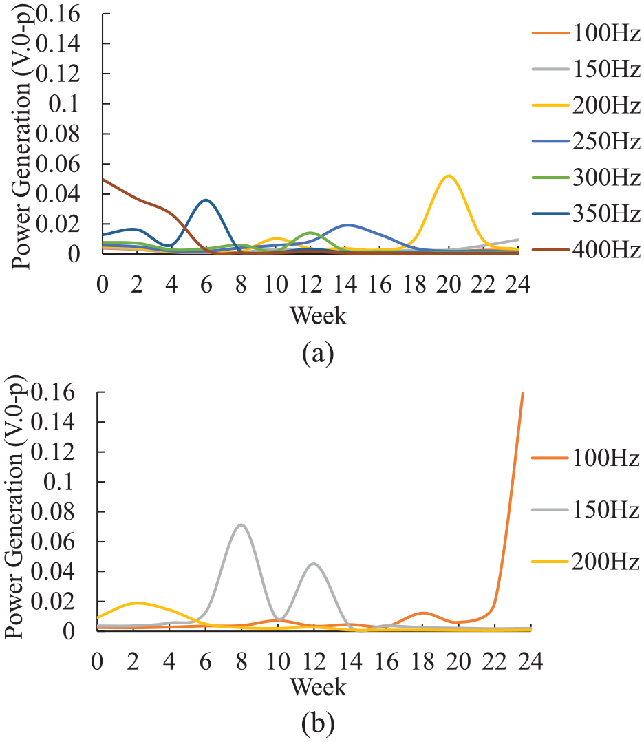
Power generation of 40°C NaCl wet and dry condition in every target frequency: (a) at 20 mm and (b) at 30 mm. NaCl: sodium chloride.
For a cantilever length of 20 mm, the target frequencies of 350 and 300 Hz offer valuable insights into the system’s effectiveness in detecting corrosion. Figure 18 depicts the power generation over 24 weeks for the two target frequencies across four different conditions. The data reveal that, for the 350 Hz frequency, submerged conditions are the most detectable, with higher power generation observed at 40°C compared to 20°C as displayed in Figure 18(b) and (d). As presented in Figure 18(a) and (c), deionized water typically produces higher power than NaCl, especially in the early weeks. In the early weeks, submerged conditions exhibit a slower frequency decrease than wet and dry conditions, allowing stable resonance and larger vibration amplitudes, leading to higher power generation. This stability is more evident in deionized water, where the absence of chloride ions enables a protective corrosion layer to form, minimizing disruptions to MEMS-SAMS resonance. 50 In contrast, NaCl accelerates uneven corrosion, disrupting resonance and causing fluctuating power generation.
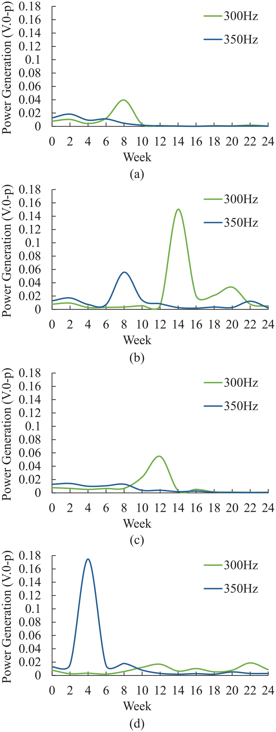
Power generation of target frequency at 350 and 300 Hz: (a) 20°C NaCl in wet and dry condition, (b) 40°C NaCl under submerged condition, (c) 20°C deionized water in wet and dry condition, and (d) 40°C deionized water under submerged condition. NaCl: sodium chloride.
Wet and dry condition further amplify corrosion due to frequent oxygen and chloride exposure, promoting unstable rust formation (β-FeOOH), 51 leading to a sharper frequency drop. Environmental factors like temperature and humidity also influence corrosion rates, with higher temperatures increasing metal reactivity and humidity facilitating electrochemical reactions.52,53 Over time, NaCl conditions cause more significant frequency shifts due to structural weakening, while submerged environments sustain electrochemical activity longer despite an initially slower corrosion rate.
At 300 Hz target frequency, significant power generation begins later in the experiment, with the first noticeable peak under 20°C NaCl solution in wet and dry condition occurring around week 8 (Figure 18(a)). This implies that power generation in wet and dry conditions is generally detected earlier than in submerged conditions at this frequency. However, deionized water and submerged environments produce higher power outputs compared to NaCl and wet-dry conditions. While NaCl accelerates the corrosion process, the resulting power generation is lower due to the aggressive and uneven corrosion patterns, which disrupt the resonance conditions more than in deionized water.
The target frequencies of 200 and 150 Hz in a 30 mm cantilever length are key for detecting corrosion-related changes. Figure 19 (power generation of target frequencies at 200 and 150 Hz under varying conditions) provides an analysis of these frequencies across four scenarios. In both 200 and 150 Hz, the 40°C conditions consistently produce higher and earlier power peaks compared to 20°C. This suggests that corrosion begins earlier and progresses more rapidly at 40°C, while the case with 20°C shows slower and more stable corrosion rates.
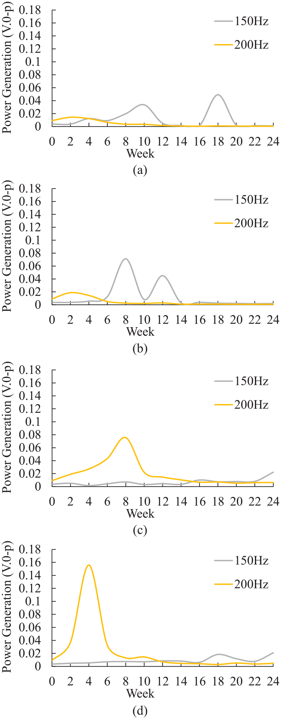
Power generation of target frequency at 200 and 150 Hz: (a) 20°C NaCl in wet and dry condition, (b) 40°C NaCl in wet and dry condition, (c) 20°C deionized water under submerged condition, and (d) 40°C deionized water under submerged condition. NaCl: sodium chloride.
Regarding 200 Hz frequency, submerged conditions consistently show higher power generation than wet and dry conditions. The higher power in submerged conditions results from lower corrosion rates, producing stronger vibrations and, consequently, more power generation. The distinct power differences between submerged and wet-dry environments make 200 Hz optimal for distinguishing between them. The system can accurately detect and identify the submerged state by setting a power threshold above the wet and dry conditions. At 150 Hz, the 40°C NaCl in wet and dry condition displays an early and more prominent power peak, indicating more severe corrosion in that environment. This makes 150 Hz an ideal frequency for the rapid detection of aggressive corrosion, especially in environments containing NaCl. In contrast, submerged conditions are less detectable at 150 Hz due to slower and less severe corrosion processes. This frequency allows for early detection of corrosion in more aggressive environments.
These frequencies enable accurate and early detection of environmental conditions, ensuring effective monitoring. In summary, for the overall detection at a 30 mm cantilever length, 200 and 150 Hz are recommended due to their balance of early detection and alignment with actual corrosion patterns; 200 Hz is suited for early environmental identification, while 150 Hz is preferable for detecting the onset of aggressive corrosion.
Based on the overall results of the electrical output at the target frequencies, the observed changes at 350 and 300 Hz for 20 mm measurements, and 200 and 150 Hz for 30 mm measurements, suggest that these values are indicative of the onset of corrosion or can help differentiate between environmental conditions. By using two target frequencies, the system can detect corrosion at different stages and distinguish between areas exposed to different environmental factors. For example, one frequency may reflect early corrosion onset, while the second may signal more severe degradation. This dual-frequency approach allows for more accurate identification of corrosion-prone areas and ensures better adaptability to varying structural and environmental conditions. These frequencies were identified as significant markers in the earlier analysis of power generation and corrosion detection.
The findings show that MEMS-SAMS devices effectively monitor corrosion by wind degradation across various environments. In marine settings with constant NaCl exposure, monitoring at target frequencies enables early detection of aggressive corrosion before structural integrity is compromised. While submerged conditions initially cause slower corrosion, sustained electrochemical activity impacts material properties, making long-term monitoring crucial. Using MEMS-SAMS in marine structures can enhance predictive maintenance, reduce failure risks, and extend service life.
Traditional SHM methods, such as wire sensors3,4,54 and gauze techniques,5,55 often lack real-time data, making it difficult to track corrosion progression effectively. In contrast, MEMS-SAMS technology offers significant advantages, as highlighted in Table 3. By integrating SAMS into MEMS, it provides continuous, battery-free corrosion monitoring in chloride-rich environments. MEMS-SAMS is a compact, self-powered system designed for large-scale infrastructure applications, such as bridges, ports, and offshore structures. Unlike traditional monitoring systems that require complex wiring and external power sources, MEMS-SAMS can be easily installed on RC surfaces to provide real-time corrosion data. Since the components, including MEMS sensors and Fe-based SAMS, are affordable and widely available, large-scale adoption would further reduce production costs. As demand increases, economies of scale will drive prices lower, making MEMS-SAMS an even more cost-effective solution. Additionally, its minimal maintenance requirements result in lower long-term costs compared to traditional methods. By integrating MEMS-SAMS into existing SHM frameworks, infrastructure managers can efficiently monitor corrosion, make timely maintenance decisions, and extend the lifespan of critical structures.
Traditional methods versus MEMS-SAMS.
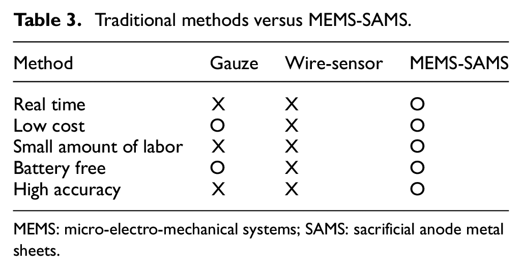
MEMS: micro-electro-mechanical systems; SAMS: sacrificial anode metal sheets.
However, this experiment in the present study is based solely on the environmental conditions around the structure. To align these predictions with the actual corrosion of rebar in concrete structures, further investigation on HCP measurements should be conducted to establish a relationship between the corrosion environment and concrete behavior. Correlation between electrical output and HCP measurements will provide deeper insights. It has also been observed that as corrosion increases, particularly in wet and dry conditions, power generation decreases significantly. This severe corrosion necessitates ensuring that the power generated is sufficient to trigger corrosion alerts from MEMS-MEH device. Future experiments should consider whether the target frequency and amplitude in each condition are enough to provide the necessary energy for these alerts. Furthermore, while Fe was selected as the optimal material for SAMS, its long-term durability under extreme environmental conditions requires further study. Understanding how material degradation affects frequency response over extended periods will enhance the reliability of MEMS-SAMS for practical applications.
Future research should cover a broader scope to ensure comprehensive understanding before practical application in real situations. Validation of the MEMS-SAMS system in field conditions is essential to ensure its reliability and applicability. Real-world environments introduce complex variables, such as wind-induced vibrations and traffic loads that could interfere with the sensor’s ability to detect corrosion signals. Although the system is designed to focus on vibrations caused by changes in the material properties of the sacrificial anode, it is important to evaluate these external factors to ensure they do not interfere with their primary measurements. Field testing should include deploying MEMS-SAMS sensors in different structural settings, such as bridges and buildings, to examine their performance under various environmental conditions. Addressing these challenges will help demonstrate the feasibility of integrating MEMS-SAMS systems into established SHM frameworks. A detailed investigation of these factors in real-world scenarios is essential to improve the system’s reliability and effectiveness.
Conclusions
This study aimed to develop an integrated system using MEMS devices and SAMS to detect high-risk corrosion zones, particularly in chloride-rich environments. This research advances evolving SHM for RC structures by combining the sensitivity of SAMS with the precision of MEMS-based frequency monitoring.
Fe was confirmed as the most effective sacrificial material, exhibiting significant and consistent frequency degradation under varying exposure conditions, reinforcing its suitability for integration with MEMS devices.
This work addresses key challenges in corrosion detection, including material selection and system performance, which provides a solid foundation for future developments. Future research should focus on field validation of the proposed system and exploring the long-term performance of the system in real-world infrastructure monitoring.
Footnotes
Declaration of conflicting interests
The author(s) declared no potential conflicts of interest with respect to the research, authorship, and/or publication of this article.
Funding
The author(s) disclosed receipt of the following financial support for the research, authorship, and/or publication of this article: This research was supported by JST-JICA SATREPS and JST SPRING (Grant Number: JPMJSP2119).