






Abstract
This work presents an experimental investigation of a stand alone directional structural health monitoring (SHM) system based on a frequency-steerable acoustic transducer (FSAT) operating in pulse–echo mode. A single transducer bonded at the center of a 1000 × 1000 × 1 mm aluminum plate was used to perform damage detection and localization by exploiting the frequency-dependent beam steering characteristics of the FSAT. Directional scanning of the surrounding structure was achieved without mechanical movement or phased-array electronics. Damage detection employed baseline comparison using a root mean square metric applied to reflected Lamb wave signals. Both directional detection at fixed actuation frequencies and spatial scanning via frequency sweeps were experimentally demonstrated. The system successfully detected and localized multiple damage types, including drilled holes and attached disk masses with a diameter of
Introduction
Ultrasonic guided waves (UGWs), a class of elastic waves that propagate within structural components, have garnered considerable attention in the fields of structural health monitoring (SHM) and nondestructive testing and evaluation across diverse industries. Their applications encompass inspection and flaw detection in transportation infrastructure,
1
including the assessment of corrosion growth in ships as presented by Zima et al.
2
and petrochemical systems as exposed by Wang et al.,
3
as well as in aerospace structures. In particular, UGWs have demonstrated notable efficacy in detecting debonding in composite stiffened structures,
4
among other defect types. This increasing interest is attributed to their significant potential for damage detection, characterized by their ability to propagate over long distances with relatively low amplitude attenuation while maintaining sensitivity to various forms of structural defects as demonstrated by Abuassal et al.
5
and Zima.
6
Consequently, UGWs are especially valuable for continuous, embedded inspection of complex structures.7,8 When the structural thickness is on the order of the UGW wavelength, Lamb waves propagate along both surfaces of plate-like structures. These waves have been extensively studied and, when combined with wavelet analysis, offer an effective method for quantification
9
and extraction of relevant structural information. Lamb waves exhibit two distinctive dispersion characteristics, with modes whose propagation differs relative to the structure’s axis of symmetry, known as the symmetric (S) and antisymmetric (A) modes. The study by Kalgutkar and Banerjee
10
shows that the energy of scattered responses is predominantly governed by the
In SHM, the generation and acquisition of UGWs are commonly achieved using piezoelectric transducers, particularly lead zirconate titanate (PZT) devices, which remain among the most widely adopted sensing technologies.11,12
Among these approaches, phased arrays (PAs) composed of multiple transducers have been extensively investigated due to their ability to perform dynamic beam steering and focusing without mechanical movement of the transducers. 13 Such capabilities enable rapid inspection and high spatial resolution over relatively large areas, demonstrating effectiveness in damage detection and localization in both metallic and composite structures. 14 For instance, advanced array configurations can selectively generate and steer guided wave modes to achieve precise defect localization.
However, despite these advantages, phased-array-based SHM systems present significant practical limitations that hinder their widespread deployment in real structures. Their operation relies on numerous individual transducer elements, each requiring dedicated wiring, actuation, and acquisition channels. This results in substantial increases in system weight, installation effort, and hardware complexity, particularly in large-scale applications such as aerospace or transportation systems. 15 Moreover, the scalability of such systems is constrained by the rapid growth in cabling and data acquisition requirements as the monitored area increases.
These challenges are well illustrated by the work of Yu and Giurgiutiu, 16 where a two-dimensional array required a minimum of 16 transducers and extensive wiring to achieve full 360° directional coverage. While such configurations provide powerful imaging capabilities, their implementation complexity highlights a key barrier for practical, large-scale SHM deployment. In this context, frequency-steerable acoustic transducers (FSATs) offer a promising alternative approach to directional guided-wave excitation. Instead of relying on spatially distributed arrays, FSATs achieve beam steering through frequency-dependent wave-number characteristics, enabling directional control using a single transducer element as exposed by Senesi and Ruzzene 17 and Baravelli et al. 18 This mechanism eliminates the need for multielement synchronization and significantly reduces cabling and instrumentation requirements. As a result, FSAT-based systems provide a compelling solution for SHM applications where low system complexity, reduced wiring, and ease of integration are critical. In particular, they enable large-area inspection and angular damage localization using a minimal number of channels, offering a favorable trade-off between directional capability and practical deployability compared to conventional phased-array approaches.
The FSAT concept has been progressively developed over the past decade as a promising alternative to conventional, highly instrumented PAs for guided-wave inspection and localization. Early work demonstrated the capability of spiral FSAT designs to perform two-dimensional imaging and direction-dependent signal mapping using a dual-channel configuration. 19 Subsequent developments employed FSATs for source localization in plate structures, 18 with further validation of their directional capabilities through finite element simulations and experimental characterization. 20 More recently, unidirectional FSAT designs have been proposed to mitigate directional ambiguities inherent in earlier FSAT implementations, enabling improved guided wave damage imaging. 21 Despite these advances, prior studies have largely focused on simplified scatterers or demonstrations of source localization, often examining only a single scatterer such as a magnet at a time. They have not fully addressed the complex interactions between FSAT actuation/sensing and real physical structural damage exhibiting complex scattering behavior. In contrast, the present study uniquely investigates the pulse-echo interaction of FSAT actuation and sensing with multiple concurrent physical damages, demonstrating simultaneous detection and localization of multiple scatterers with complex wave interactions. In this context, the present work makes the following distinct contributions:
Incorporation of real structural damages, resulting in complex scattering behaviors that surpass those of the simplified magnetic or artificial scatterers used in prior FSAT research.
Systematic demonstration of complete polar-coordinate damage localization
Parametric analysis of excitation signal parameters and damage–sensor distances, leveraging an established reference damage methodology.
Successful detection, localization, and discrimination of multiple physically realized damages exhibiting complex scattering.
Identification and discussion of limitations in the latest FSAT design concerning wavefield transmission efficiency in different directions.
This work presents a directional damage detection system for SHM based on a FSAT operating in pulse–echo mode using UGW for practical applications. The proposed system leverages key advantages of PAs while mitigating several of their inherent limitations, enabling both local and large-area structural monitoring. 22 The focus is placed on the development of a sensitive and efficient system capable of interrogating extensive structural regions while processing the acquired data in a manner that yields accurate, intuitive, and application-oriented results.
The remainder of this article is organized as follows: The second section presents the theoretical background, including the operating principles and wavenumber-domain directivity characteristics of the FSAT, as well as the influence of plate geometry on UGW velocity. The third section describes the experimental setup, detailing the SHM system, introducing a PZT sensor network that works only as support for the study of the stand alone FSAT damage detection, the induced damage scenarios, and the signal characteristics used for damage detection. The fourth section presents and discusses the damage detection and signal processing results, providing a comparative evaluation of the employed methods under varying damage conditions and system parameters. Finally, the fifth section summarizes the main findings and contributions of the study.
Theoretical background
Frequency-steered acoustic transducers and wave dispersion
FSATs exploit the dispersive nature of UGW in plate-like structures to achieve directional control of acoustic radiation through frequency variation. Unlike conventional PAs, which rely on spatially distributed phase delays, they encode directionality into their spatial geometry based on the underlying principle of directional selectivity obtained through controlled excitation in the wavenumber domain.
In the wavenumber domain, the directivity of wave propagation in thin plates is governed by dispersion relations that link excitation frequency
The frequency-dependent directivity of an FSAT can be expressed as

where
The directivity can be interpreted as the spatial Fourier transform of
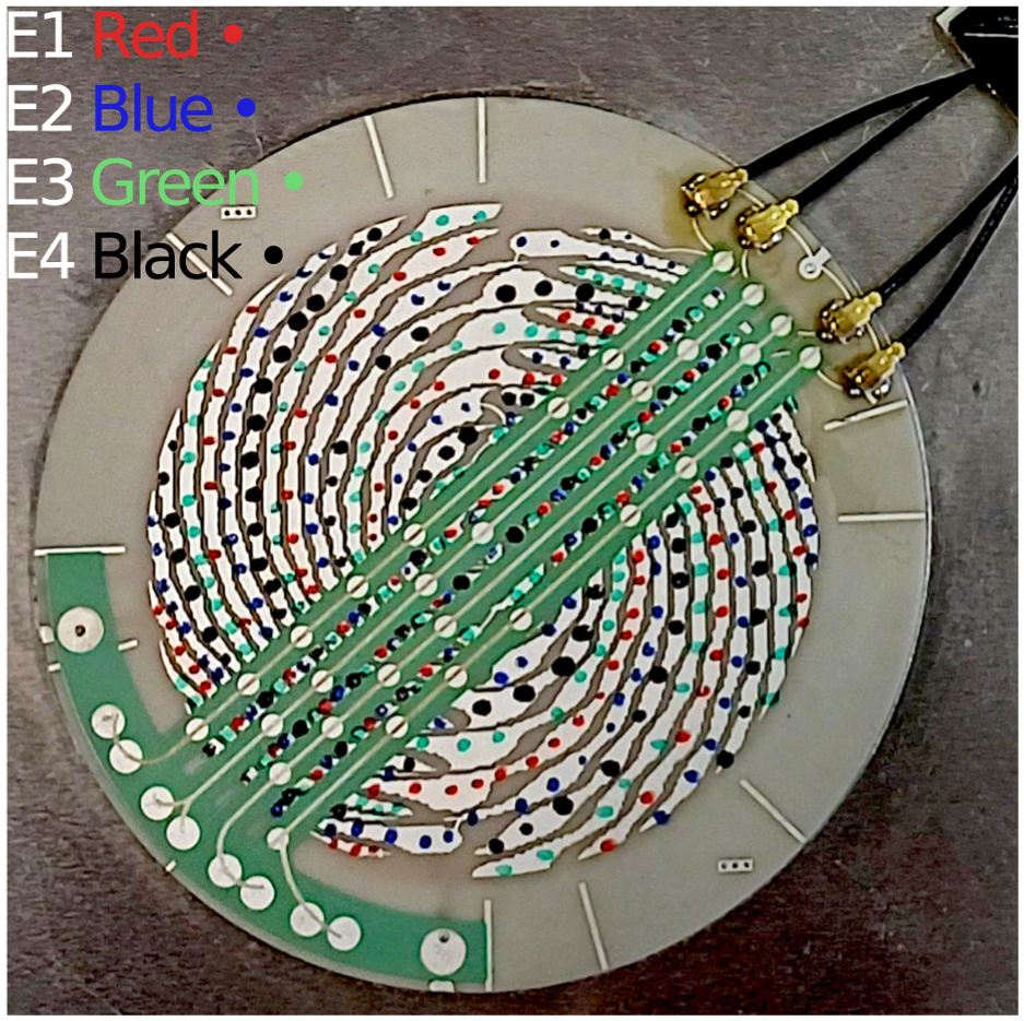
Close-up photograph of the FSAT showing the four electrodes (E1–E4) and their connections to the electronic hardware through UF.L connectors. This image provides a visual reference for the electrode configuration. FSAT: frequency-steerable acoustic transducer.
In essence, the transducer acts by filtering narrow wavenumber bands. In the FSAT approach, the central wavenumber of each band varies with the angle.20,23,24 So, depending on the angle of propagation, the transducer produces a variable wavenumber filtering effect. Knowing the dispersion curves of the inspected medium, it is possible to associate a specific frequency to each wavenumber and, consequently, to the angle of propagation, as illustrated in Figure 2. It is worth noting that the 180° ambiguity in the frequency to angle conversion can be removed by driving the channels corresponding to the four electrodes with quadrature signals, as extensively discussed by Mohammadgholiha et al. 21
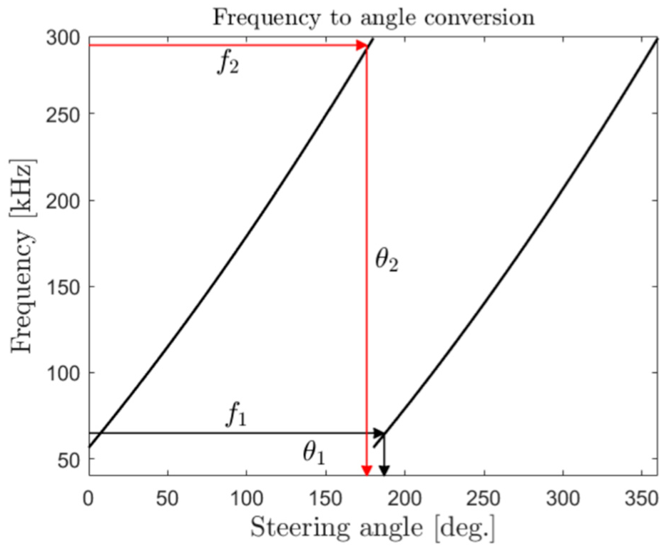
Frequency to angle conversion as derived from the wavenumber–angle relation determined by the FSAT design and the frequency to wavenumber relation imposed by the dispersion curve of the
Rayleigh–Lamb wave dispersion in plates
The guided waves employed in this study while they propagate in thin plates exhibit frequency-dependent dispersion behavior, such that their group velocities vary with frequency. This behavior is governed by the Rayleigh–Lamb equations, which describe the propagation of symmetric (

where

and

The Rayleigh–Lamb equations are solved numerically, taking into account the material and geometric properties of the propagation medium, in order to obtain the dispersion relations. For this study, the wave propagation is considered in a

The corresponding group velocity dispersion curves for the
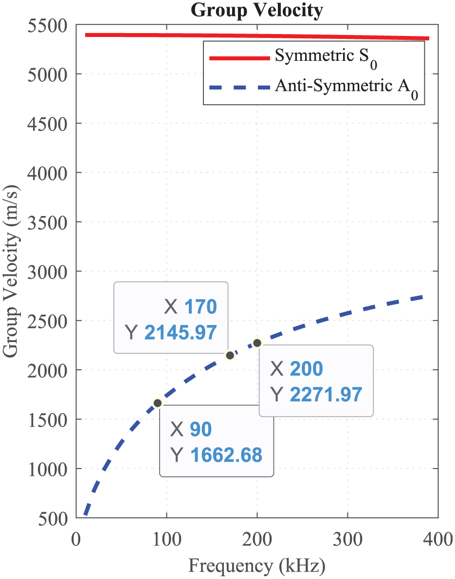
Dispersion curves for the
System description
Experimental setup
The experimental setup comprises an aluminum plate measuring
A total of 11 sensors are arranged in a ring around the FSAT with a radius of
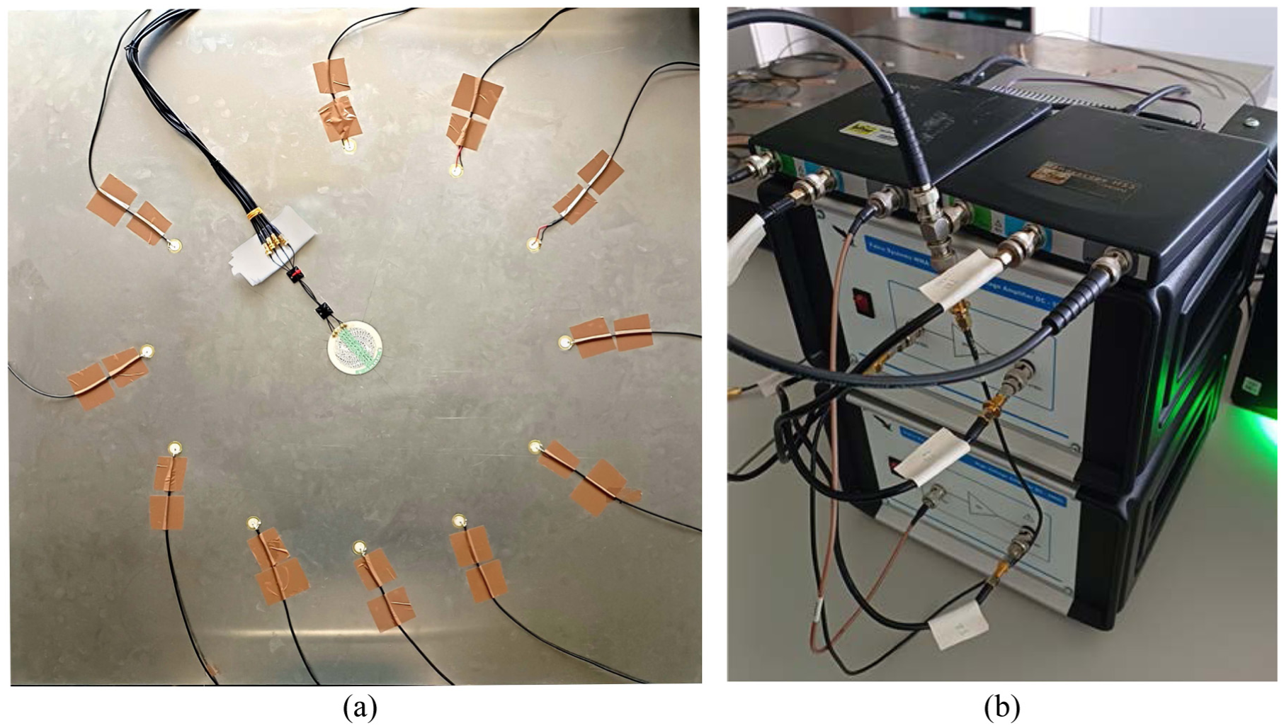
Experimental setup employed in this study: (a) instrumented aluminum plate featuring the FSAT and auxiliary PZT network and (b) corresponding actuation system. (a) Experimental setup illustrating the FSAT transducer bonded to an aluminum plate, accompanied by an auxiliary surrounding PZT sensor network used for pitch-catch measurements. This network provides an independent reference to validate the pulse-echo-based damage localization approach. Damage localization is conducted using the FSAT in a standalone pulse-echo configuration. (b) Actuation system comprising two Handyscope HS5 data acquisition units and two high-speed, high-voltage WMA-300 amplifiers, enabling precise excitation of the FSAT. FSAT: frequency-steerable acoustic transducer; PZT: lead zirconate titanate.
Excitation and signal acquisition
The actuation signals consist of sinusoidal burst waveforms modulated by a Hann window with carrier frequencies ranging from 60 to 300 kHz, generating Lamb wave fields. As demonstrated by Reyes et al.,26,27 the FSAT exhibits an angle–frequency relationship within this frequency range, enabling wave field steering from 0 to 180°, with the angles referenced in Figure 7. According to the study by Mohammadgholiha et al., 23 unambiguous steering of UGWs by the FSAT requires a double excitation signal in quadrature, as depicted in Figure 5. This phase shift between the actuation bursts is maintained consistently across the entire frequency range.
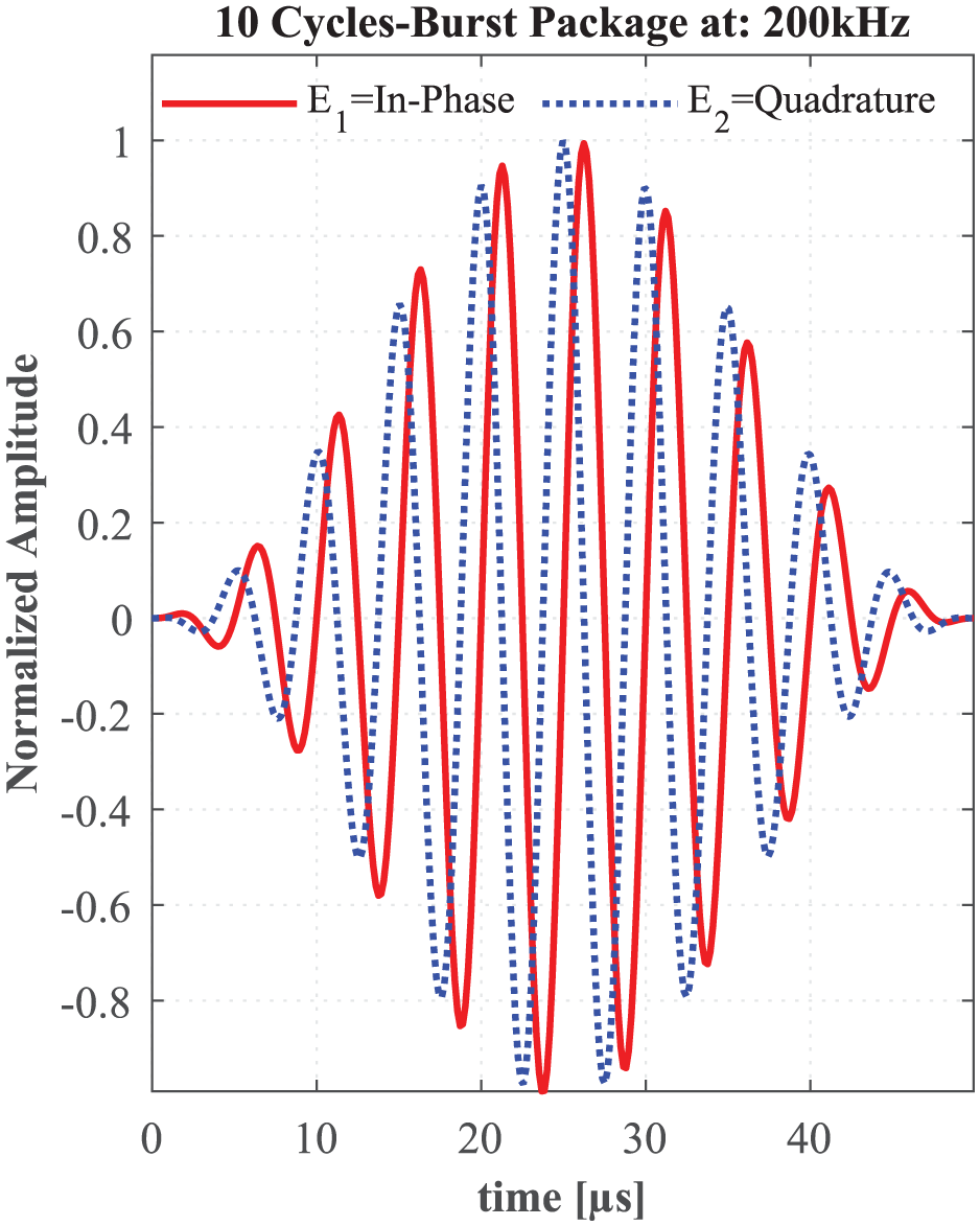
Exemplary tone-burst excitation signals at 200 kHz, applied in quadrature to electrode 1 (in-phase) and electrode 2 (quadrature-phase), used to drive the FSAT and generate a main lobe of guided waves in the 120° direction. Switching the phases of E1 and E2 redirects the main lobe to the 300° direction. FSAT: frequency-steerable acoustic transducer.
Signal generation and acquisition are performed using two Handyscope HS5 units (TiePie Engineering, Sneek, The Netherlands) paired with two high-speed, high-voltage WMA-300 amplifiers (Falco Systems, Amsterdam, The Netherlands), as shown in Figure 4(b). The Handyscopes generate and synchronize the actuation signals across the full frequency range, which are then amplified by the WMA-300 units and delivered to the FSAT electrodes E1 and E2 to produce ultrasonic waves. To cover the entire plate area surrounding the FSAT, the Handyscopes implement channel switching to alternate between the upper (North) and lower (South) sensor regions, as illustrated in Figure 7.
For sensing, the Handyscope acquisition channels are connected both to the piezoelectric sensor network to perform pitch-catch measurements, and to FSAT electrodes E3 and E4, which serve as piezoelectric sensors for pulse-echo measurements. The acquired signals are digitized with a 14-bit analog-to-digital converter at a sampling frequency of 100 MHz. The system does not rely exclusively on measurements of the out-of-plane wave components, such as those obtained using laser Doppler vibrometers. The objective was to develop a SHM system capable of discriminating damage by analyzing comprehensive data from all measured wave components.
Damage types and placement
Two types of damage were introduced at various locations on the plate:
Artificial (reference) damage: Reversible reference defects were implemented by attaching thin cylindrical aluminum masses (
Drilled holes: Four holes with diameters of
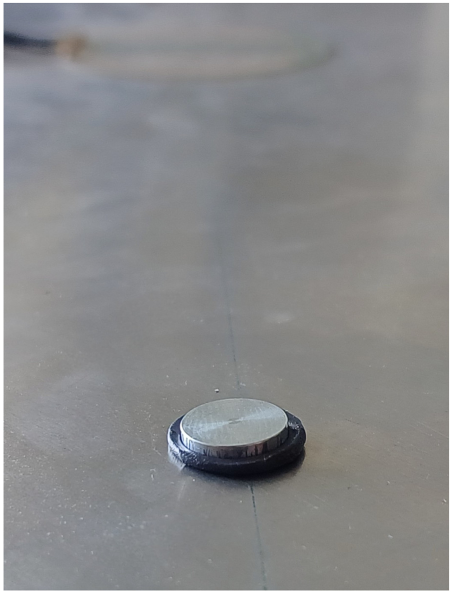
Photograph of the reversible (reference) damage model in the form of an aluminum disk with a diameter of
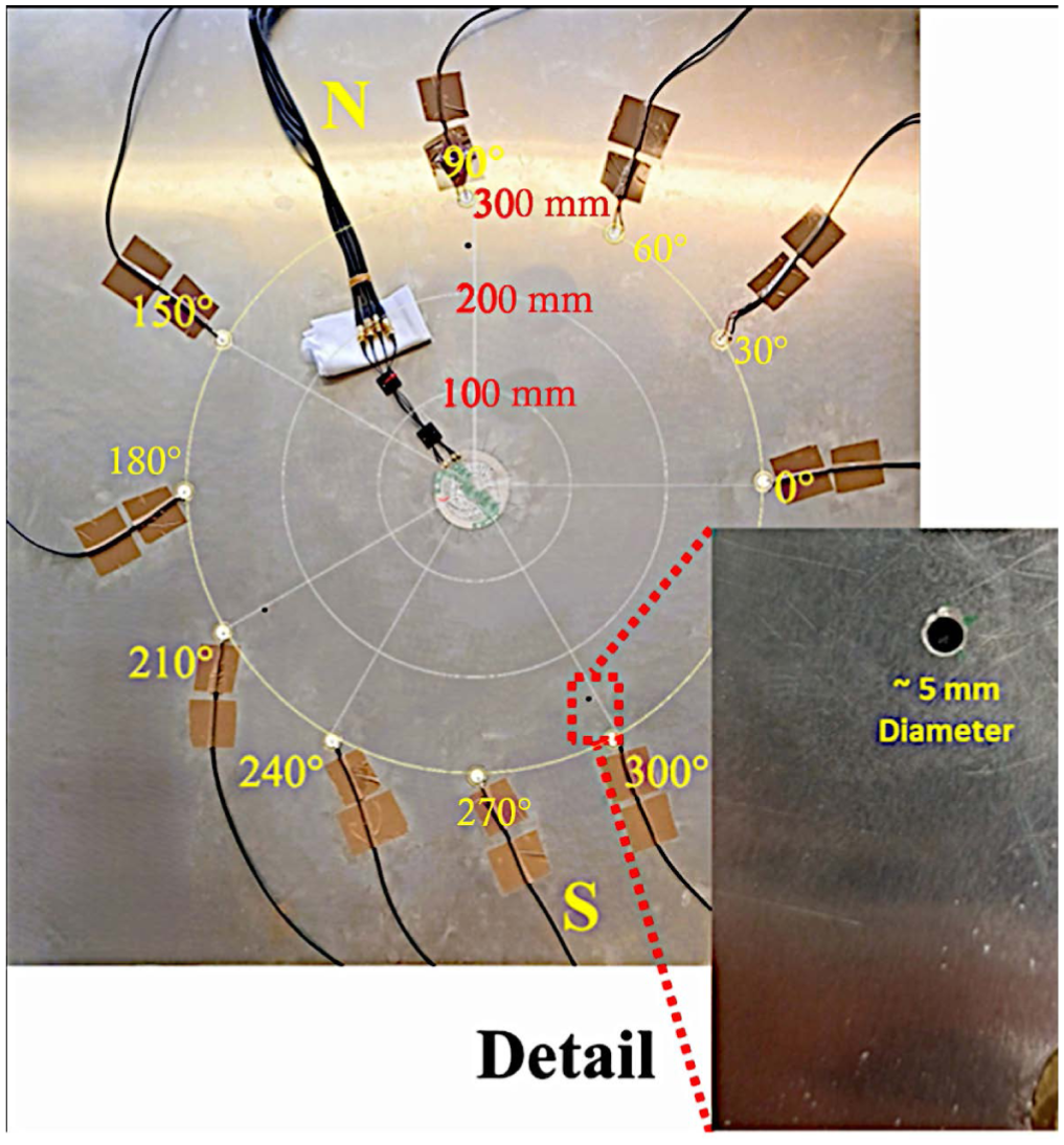
Structure under study: aluminum plate measuring
Damage detection methods
Damage detection was performed simultaneously using two complementary approaches:
Pitch-catch measurements: Utilizing the sensor network, where one transducer acts as the actuator and others as receivers.
Pulse-echo measurements: Using the FSAT electrodes E3 and E4, which act as both actuator and sensor to capture reflected signals from defects.
Measurements were conducted at various distances and azimuthal angles to evaluate the FSAT’s capability to detect damage based on its location around the transducer.
Data acquisition and damage identification procedure
For each damage location, a set of 50 measurements was acquired, complemented by an additional 50 measurements on the pristine (undamaged) structure. This approach ensured a statistically significant number of independent samples, accounting for variability due to electronic noise, temperature fluctuations, electromagnetic crosstalk, and other sources of measurement uncertainty. The resulting dataset thus includes a comprehensive family of noise data.
To evaluate the FSAT’s directional and distance-dependent damage detection capabilities and its wave-field behavior, actuation signal bursts with varying cycle lengths were employed, specifically comprising 7, 10, and 13 cycles. Longer wave packets are expected to generate a more directive main lobe, which can improve the angular resolution in damage detection. However, for pulse-echo testing at short distances, longer wave packets—such as those with 13 cycles—may introduce measurement artifacts. This occurs because the total duration of the actuation burst increases with the number of cycles, and when the damage is located close to the FSAT (i.e., in the transducer blind zone ), the reflected wave arrives while the actuation signal is still being emitted. This effect is particularly pronounced at direction for lower frequencies, where the longer cycle durations may exacerbate the overlap. Moreover, due to the time-bandwidth uncertainty, narrower band pulses worsen the temporal resolution in the estimation of wave ToF.
The acquired dataset spans a frequency range from 60 to 300 kHz in 10 kHz increments, providing a balance between data volume and angular resolution for wave field steering and sensor coverage. For the analysis presented here, a subset of the full dataset was used, including all damage scenarios and actuator-sensor pairs, with selected representative positions highlighted. This focus facilitates evaluation of the FSAT’s performance under the given experimental conditions, particularly its interaction with the dominant
All acquired signals underwent preprocessing via a Butterworth bandpass filter centered on the carrier frequency with a bandwidth of
Although differential signal processing and filtering reduce unwanted artifacts, UGWs are inherently susceptible to reflections and interference effects, which can influence the results. To mitigate these effects during damage detection and localization, a time-windowing approach was applied. This windowing was based on the group velocity of the excited
As described previously a signal energy-based DI based on RMS values was selected for directional detection analysis. This indicator has demonstrated sensitivity to both reversible (artificial) 29 and permanent damage types, 30 enabling comparative evaluation. The DI is defined as the energy difference between damaged and undamaged states, computed from the pulse-echo signals across the scanned frequency range and spatial surface. For pitch-catch measurements, the DI is calculated using signals from a sensor located near the damage site.
The schematic diagram in Figure 8 provides an overview of the damage detection process and illustrates the signal propagation pathway. The procedure begins with the generation and synchronization of excitation signals using the two Handyscope devices. These signals are then amplified by two WMA-300 amplifiers before being transmitted as UGW by the FSAT towards the target damage area. The resulting echoes or received signals are captured, digitized, and transferred for processing and visualization, enabling the user to interpret the inspection results. This setup supports both pulse-echo and pitch-catch techniques.
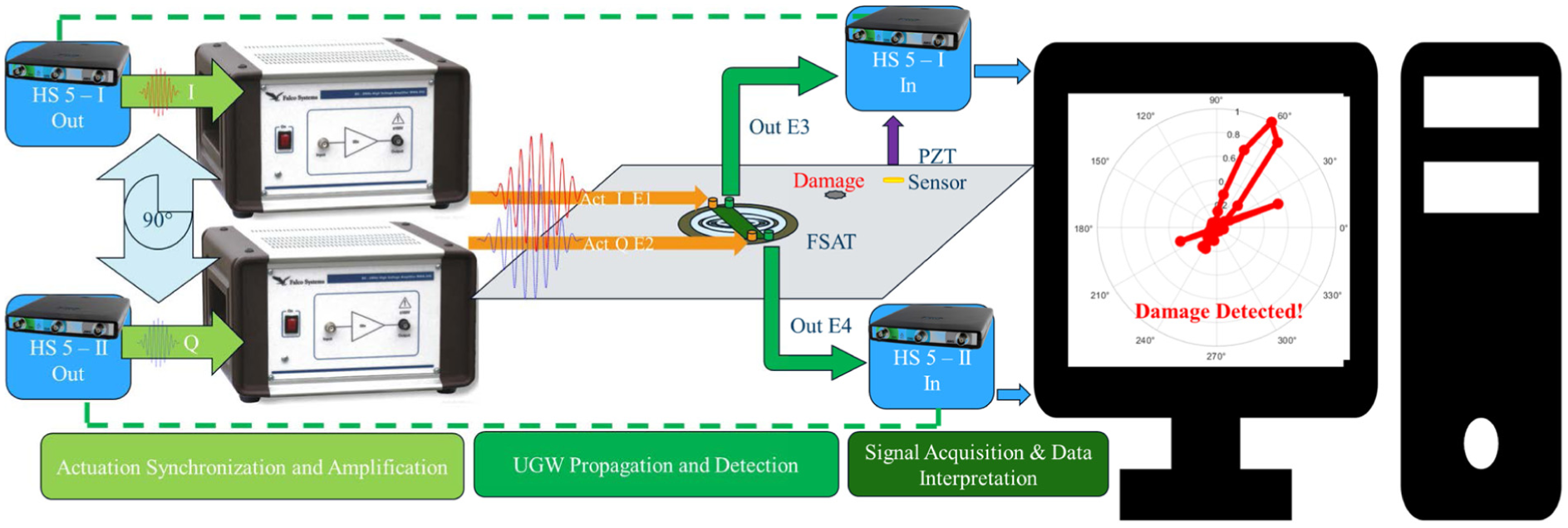
Schematic block diagram of the directional damage detection application.
Results
Damage detection
The damage detection analysis is structured into two main components for comparative evaluation: first, the results obtained via the pitch-catch method using the sensor network surrounding the FSAT are presented; subsequently, the pulse-echo method is applied following the same principles to enable a direct comparison between the two approaches.
Pitch-catch damage detection
The influence of damage—modeled as a drilled hole or the used reference damage, as detailed in the previous section on the UGWs, were recorded by the piezoelectric sensor disks as support and for comparison of the pulse-echo approach used here by the FSAT. The recorded signals of the piezo-disk positioned at 30° is illustrated in the top-left subplot of Figure 9, titled “Pitch-Catch: 90 kHz, Sensor at 30 and 300 mm.” A thorough examination reveals a consistent attenuation in amplitude and a phase shift across all 50 repetitions compared to baseline signals (in blue color) recorded prior to damage introduction.
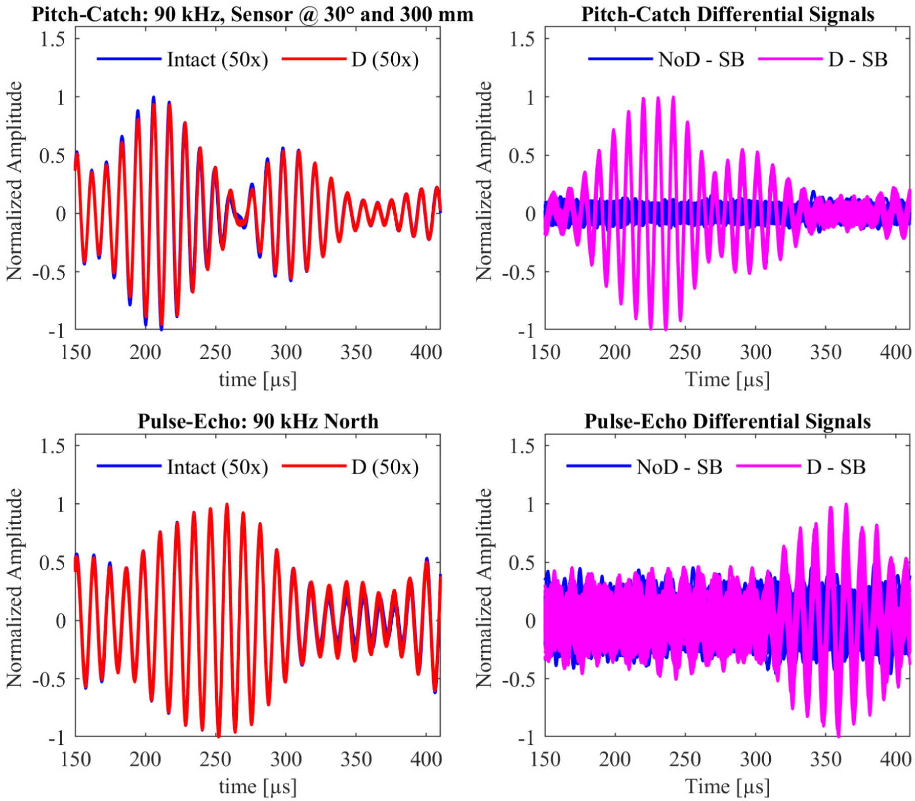
Comparison of pulse-echo and pitch–catch signals for a reference damage located 250 mm away at an angular position of 30°. For the pitch–catch method, the receiving sensor is positioned at 30° and a distance of 300 mm. The signals were recorded using the FSAT in pulse-echo mode and a PZT disk sensor in pitch–catch mode. Differential signals are calculated by subtracting the SB—the average of 50 measurements from the pristine (intact) structure—from each measurement, with NoD–SB representing the difference between intact measurements and the SB, and D–SB representing the difference between measurements after the reference damage was attached and the SB. The observed ToF of the incident and reflected waves agrees well with the expected values for the respective propagation distances, confirming localization of the damage at approximately
A 90 kHz tone burst in pitch–catch actuated on the FSAT predominantly excites the

Accordingly, the wave packet and the associated signal variations are expected to arrive at the sensor after approximately
Pulse-echo damage detection
A similar approach was adopted as for the pitch–catch method: a 90 kHz tone-burst signal was actuated by the FSAT, generating UGW propagating toward the damage located at 30°. Again, the group velocity of the
SNR in dB at different damage locations on the structure, measured in pulse-echo mode.

SNR: signal-to-noise ratio; dB: decibels.
The values illustrate the variation of SNR depending on the angular position of the damage.
DI and angular damage localization
DIs are derived from the energy content of differential signals obtained by subtracting the SB from each measured signal (before and after damage). For each angular segment, 50 differential signals are evaluated. To isolate the damage-reflected wave packet, an adaptive time gate is applied based on the calculated ToF of the
Within this time window, the RMS value is calculated as

where
The normalized polar plot consolidates all measurement data into a single, interpretable visualization, enhancing understanding of FSAT behavior. Notably, the emergence of sidelobes confirms excitation of UGW in directions other than the main lobe, consistent with prior FSAT simulation studies. 26
Another key observation pertains to damage localization at low frequencies. As the actuation frequency approaches the lower operational limit (60 kHz), significant sidelobes arise opposite to the damage direction, similar to those observed in earlier FSAT versions. 26 An example of this behavior is shown in Figure 10(b), corresponding to a damage location near a low frequency area around 90 kHz.
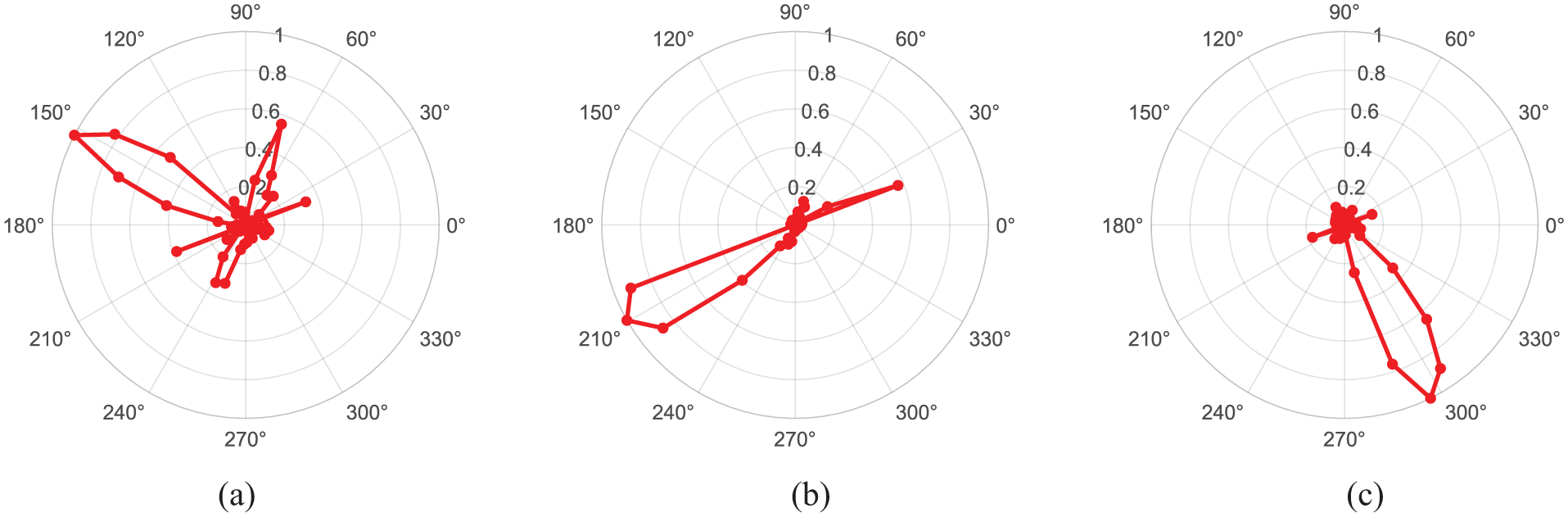
Successful damage localization using the FSAT in standalone pulse-echo mode, represented by one 3 mm and two 5 mm diameter drilled holes, positioned at various angles and located 250 mm from the transducer. (a) Main lobe pointing toward a 3 mm diameter damage at 150°, with transducer actuation frequency of 250 kHz. (b) Main lobe pointing toward a 5 mm diameter damage at 210°, with a transducer actuation frequency of 90 kHz. (c) Main lobe pointing toward a 5 mm diameter damage at 300°, with transducer actuation frequency of 200 kHz. FSAT: frequency-steerable acoustic transducer.
Furthermore, considerable variability in damage detection was observed at frequencies exceeding
For visualization purposes, the DIs are normalized individually for each measurement. This choice is motivated by the strong frequency-dependent amplitude variations arising from attenuation, dispersion, and mode-tuning effects, which would otherwise obscure lower-amplitude responses under a unified scaling. To ensure comparability across cases, an additional representation in logarithmic (dB) scale is provided (see Figure 11).

Frequency-dependent directivity of the DIs represented in logarithmic (dB) scale. The plot shows the DI energy-based distribution as a function of propagation direction for the investigated excitation frequencies. The logarithmic scaling enables comparison across measurements with significantly different amplitude levels. DI: damage indicator; dB: decibels.
Radial damage localization
After performing an angular scan of the structure around the FSAT and determining the angular location of damage, a method similar to those proposed by Márquez-Reyes et al.
26
and Mohammadgholha et al.
21
was implemented to estimate the radial position of damages. This estimation is based on the ToF as described in Equation (2), considering the entire wave path from the FSAT to the damage and back in pulse-echo mode. However, unlike the cited approaches, the method presented here does not directly use the actuated wave signals to determine the distance to the damage. Instead, it relies on differential signals, which highlight deviations from the baseline behavior. These differential signals are governed by the ToF of the carrier frequency used in a given direction, after accounting for the complex interplay of electromagnetic crosstalk and acoustic wave sensing. The performance of the pulse-echo system for damage detection at varying distances was evaluated by positioning a reference damage along a line extending from the FSAT to the circular arrangement of PZT sensors. The reference damage was placed at increments of
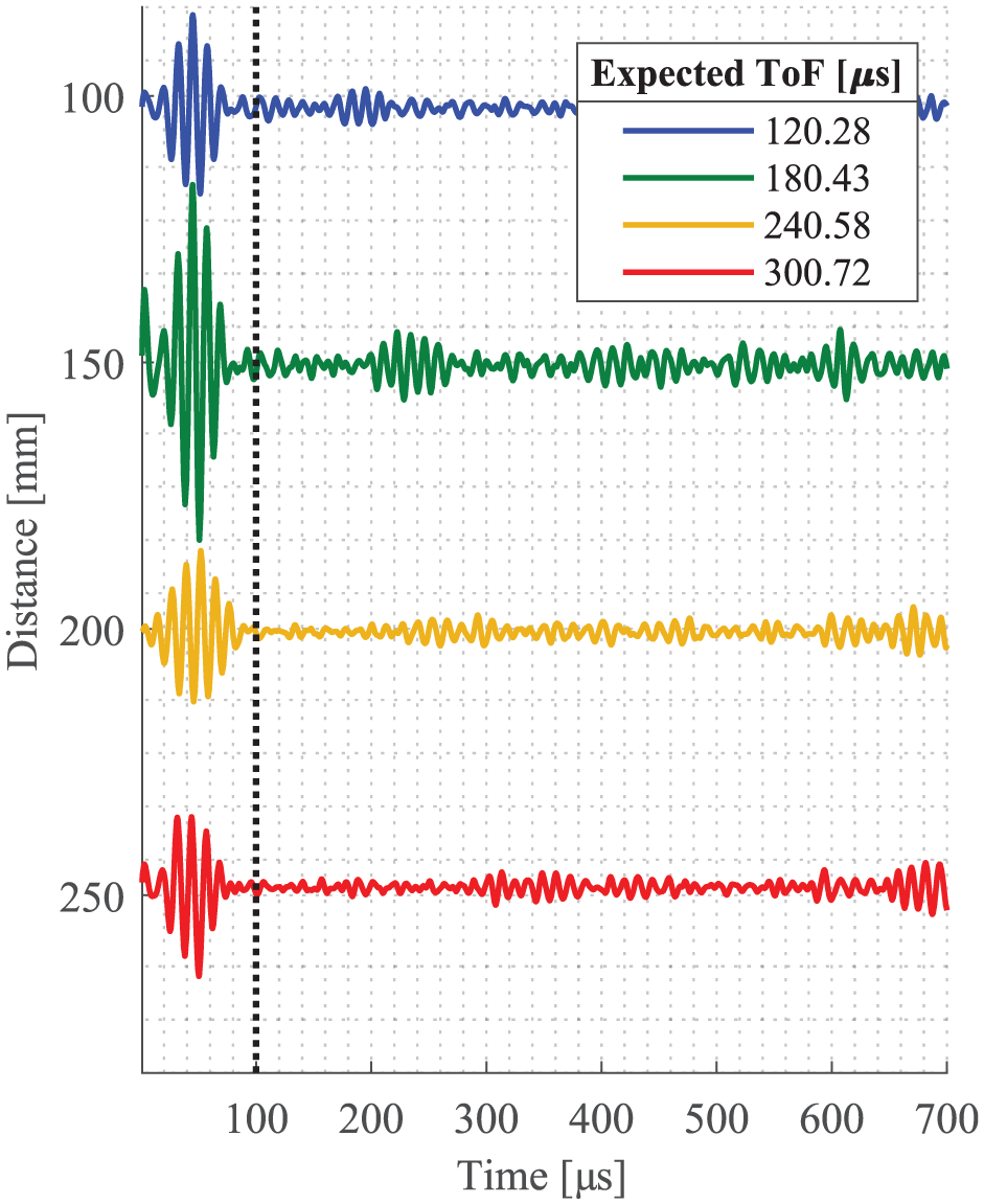
Differential signals for reference damages in the 210° direction at 90 kHz, illustrating the measured ToF of perturbations for different propagation distances. The legend indicates the corresponding estimated ToF values based on the excitation frequency, propagation direction, and damage location, showing reasonable agreement with the experimental observations. ToF: time-of-flight.
It is also noteworthy that the amplitude of the reflections tends to decrease with increasing distance. This attenuation contributes to variations in the measured DIs. However, the adjustment of the damage position required manual attachment and detachment of the reference damage at each location, introducing significant variability due to inconsistent pressure during attachment. This limitation affects the reliability of direct comparisons of DIs across different positions. Despite these challenges, the results presented in Figures 12 and 13 are broadly representative of similar observations in other directions. Notably, damage located at
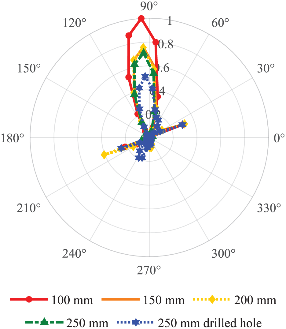
Pulse-echo localization of reference damage and comparison of various distances and real damage at 90° and 250 mm away from transducer.
An additional observation is that the main lobe corresponding to actual damage at
Actuation cycle variation
The spectral characteristics of a wave packet with a defined carrier frequency depend on its duration, commonly measured by the number of cycles of the carrier frequency. According to signal processing and antenna theory, increasing the number of cycles in the wave packet results in a narrower spectral bandwidth concentrated around the carrier frequency. This occurs because a longer time-domain signal corresponds to improved frequency resolution in the spectral domain.
For instance, a wave packet consisting of five cycles exhibits a relatively broad spectral distribution, with energy spread over a wider frequency range around the carrier. In contrast, a 10-cycle packet has a narrower spectral bandwidth and a more pronounced peak at the carrier frequency, concentrating energy closer to the center frequency. Thus, longer excitation pulses with more cycles produce a sharper spectral peak, focusing energy near the carrier frequency.
This principle was extended to the current transducer design, hypothesizing that longer wave packets would concentrate energy more effectively near the carrier frequency and the desired wave propagation direction, thereby enhancing the detection of small damages.
To investigate this, wave packets comprising 7, 10, and 13 cycles were employed to detect both reference and actual damages.
To investigate this effect, wave packets comprising 7, 10, and 13 cycles were employed for both reference and actual damage detection. Figure 14 shows the results for a reference damage located at
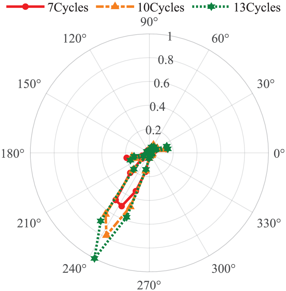
Pulse-echo localization of reference damage at 240°: comparison of actuation signals with 7, 10, and 13 cycles.
SNR comparison for different actuation cycle lengths for a
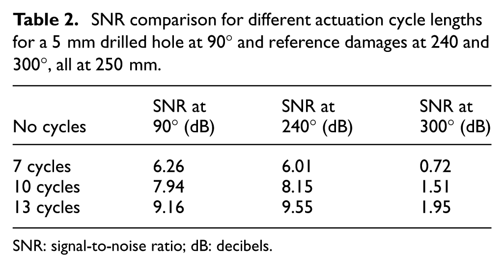
SNR: signal-to-noise ratio; dB: decibels.
The results presented in Figure 14 are representative of similar findings across other directions, where damage localization was achieved regardless of wave packet length. However, a practical application of this phenomenon emerged for locations associated with higher frequencies, where the influence of the
While longer actuation signals enhance wave energy focusing and may improve damage identification at higher frequencies, it is important to consider that extended wave packets can interfere with echo measurements. This is particularly relevant for low-frequency applications, where inherently longer wave packets are used, or when damage is located in close proximity to the FSAT.
Multiple damage localization
Following successful detection and localization of single damages of two distinct types at various positions on the aluminum structure, the more complex challenge of detecting, localizing, and discriminating multiple damages was subsequently addressed. Kalgutkar et al.
32
propose a method for multiple damage localization in wind turbine blades using guided waves. Their approach identifies several damages within a simulation-based framework employing a network of distributed transducers, where localization is achieved through spatial imaging techniques. In contrast, the present study leverages the inherent spatial scanning capabilities of the FSAT to detect variations in reflected UGWs along specific directions. To evaluate this approach, a first reference damage was positioned at a distance of
The pulse-echo guided wave responses obtained with the FSAT, illustrating the progressive detection and localization of multiple damages on the aluminum structure. Each subplot corresponds to increasing complexity in damage scenarios: (a) a single damage at 90°, (b) two damages at 90 and 225°, and (c) three damages at 90, 225, and 30°. The main lobes in each plot represent the spatial directions of the reflected signals associated with the respective damages, highlighting the FSAT’s inherent directional scanning capability for effective multidamage discrimination and localization. FSAT: frequency-steerable acoustic transducer.
Comparison of observed and expected ToF values for multiple damage localization.
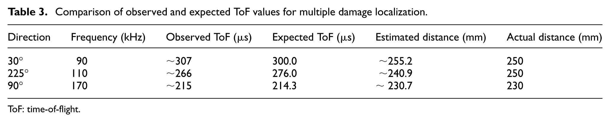
ToF: time-of-flight.
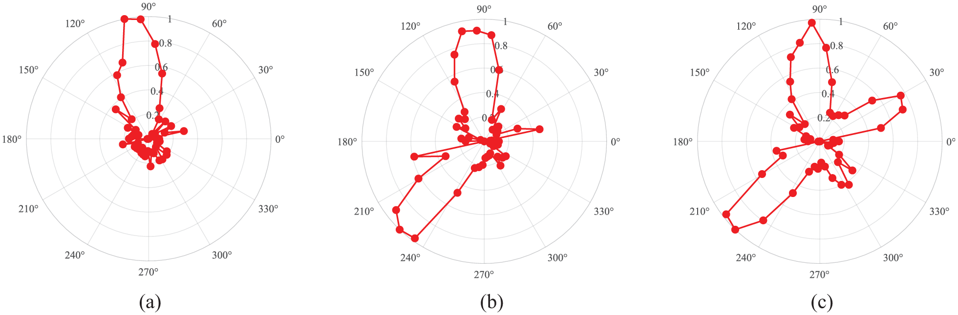
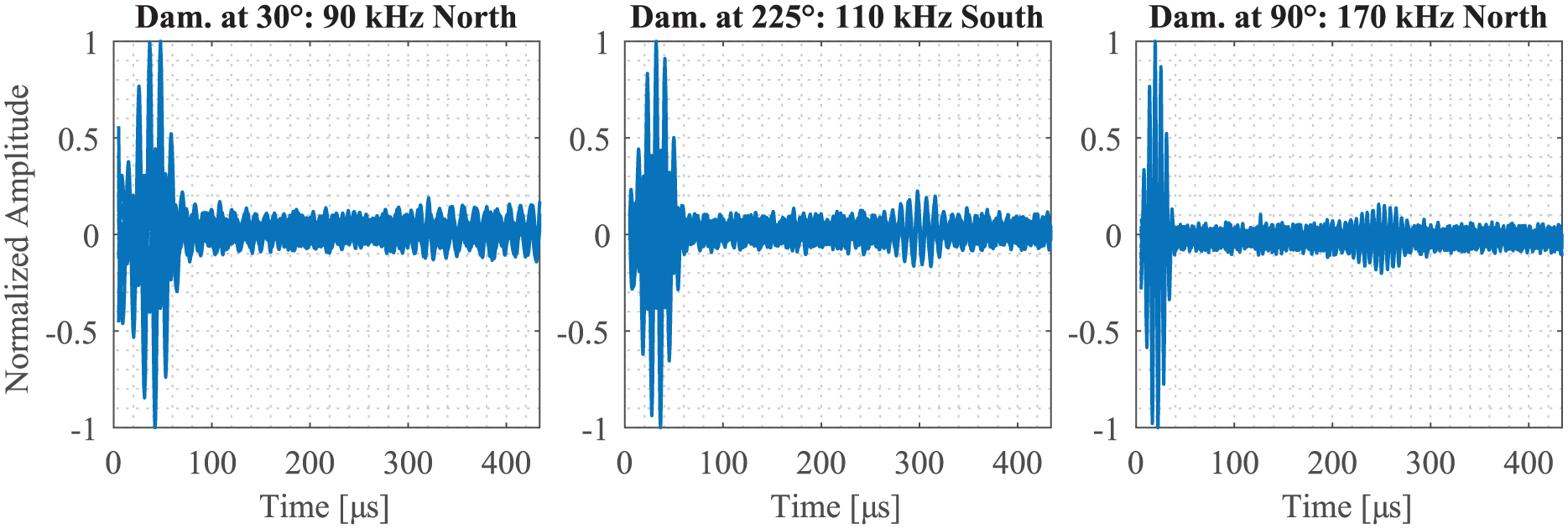
Differential signals corresponding to damages located at 30, 225, and 90°, excited, respectively, at 90, 110, and 170 kHz. The subplots (from left to right) display the differential signals extracted from the pulse-echo measurements, highlighting the disturbances in the reflected UGWs. The ToF of such perturbation in each plot corresponds to the propagation distance from the FSAT to the respective damage site. These signals underpin the multidamage localization approach, leveraging the FSAT’s spatial scanning capabilities to discriminate and locate multiple damages on the aluminum structure along distinct directions. (a) Pulse-echo response showing a distinct main lobe directed toward the damage located at 90° corresponding to 170 kHz, indicating localization of the single damage. (b) Pulse-echo response displaying two main lobes corresponding to damages at 90 and 225°, actuation frequencies for the main lobes correspond to 170 and 110 kHz, respectively, demonstrating the system’s ability to detect and localize multiple damages simultaneously along different directions. (c) Pulse-echo response illustrating three main lobes pointing toward damages at 90, 225, and 30° with the last direction corresponds to 90 kHz, confirming the FSAT’s capability to discriminate and localize multiple damages distributed at distinct angular positions on the aluminum structure. UGW: ultrasonic guided wave; FSAT: frequency-steerable acoustic transducer; ToF: time-of-flight.
Conclusion
Experimental results demonstrated that the directional damage detection system based on the FSAT transducer operating in pulse–echo mode is capable of effective damage detection and directional localization in practical applications by exploiting the transducer’s steerable beamforming capabilities. The system successfully detected different damage types, represented by drilled holes and small attached disk masses, at various locations, including defects with characteristic dimensions as small as 3 mm. Notably, the approach proved effective in simultaneously detecting and discriminating multiple damages positioned at distinct angular locations, as confirmed by the progressive identification of single, double, and triple damage scenarios. This capability underscores the system’s potential for complex SHM tasks involving multiple concurrent defects. The proposed approach enables simpler, lighter, and more scalable autonomous SHM systems, as it requires fewer transducers to interrogate larger inspection areas compared with conventional phased-array configurations or dense omnidirectional sensor networks, while remaining suitable for industrial applications. Furthermore, compatibility with conventional ultrasonic sensor networks was demonstrated, indicating that the proposed system can enhance inspection flexibility and localization accuracy when deployed within hybrid UWG-based SHM architectures. Finally, the observed relationship between beam focusing, echo energy variation, and ToF measurements as a function of defect distance provides a sound basis for full polar-coordinate localization
Footnotes
Acknowledgements
The authors sincerely appreciate the reviewers for their thorough evaluation and constructive feedback, which has significantly improved the quality and clarity of this manuscript. The authors gratefully acknowledge the support and collaboration of the HotWalls project team.

Ethical considerations
This article does not contain any studies with human or animal participants.
Consent to participate
There are no human participants in this article and informed consent is not required.
Funding
The authors disclosed receipt of the following financial support for the research, authorship, and/or publication of this article: This work was partially supported by the German Federal Ministry for Economic Affairs and Energy (BMWE), grant number 03EN4088D, and the German Research Foundation, grant number 349435502.
Declaration of conflicting interests
The authors declared no potential conflicts of interest with respect to the research, authorship, and/or publication of this article.