
Abstract
Transverse matrix cracking is the predominant failure mode in the early stages of progressive degradation, making its accurate identification crucial for ensuring the safety of carbon fiber reinforced plastics (CFRP) composite structures. However, when models trained on guided wave sensor data from one structure are applied to predict crack density in another structure with a different ply orientation, conventional deep learning methods face significant challenges due to the sensitivity of this regression task to feature scale and ply orientation. To address these challenges, we propose a domain adaptive relational graph convolutional network (DA-RGCN) model specifically designed for crack density prediction, leveraging deep domain adaptation to transfer identification knowledge learned from one laminate to another with completely different ply orientation. First, crack damage-related features are automatically extracted from sensor signals by capturing their temporal relationships during guided wave propagation. These features, along with geometric information from sensor networks, are embedded as node features within a graph structure, allowing for the learning of enhanced feature representations through the fusion of information from neighboring nodes. Subsequently, the fused features are utilized to identify crack density along each path by measuring its spatial distance from two reference states (baseline and saturation). Additionally, we employ a representation subspace distance based on principal angles to minimize distribution discrepancies between features without altering their scales. As a result, combined with the physical guidance from the damage index model, the extracted features achieve domain invariance, significantly enhancing the cross-structural generalization of the DA-RGCN. To validate the model’s capability for cross-structural identification of transverse matrix cracks, we designed transfer tasks between two layups using the CFRP Composites Dataset. The results indicate that the proposed DA-RGCN achieves an average root mean square error of 1.1841 in crack density identification, demonstrating the lowest error compared to other deep transfer learning-based and purely physics-based methods.
Keywords
Introduction
Carbon fiber-reinforced plastics (CFRP) are high-performance materials widely used in the aerospace industry due to their excellent mechanical performance and lightweight design.1–3 Laminates are the most prevalent form of CFRP composites, which consist of multiple ply layers bonded together in a specific orientation and stacking sequence. This unique layup induces strong in-ply anisotropy within the laminates, leading to the initiation and coupling of various damage modes under fatigue loading. 4 To prevent catastrophic structural failure due to damage growth, structural health monitoring (SHM) employing ultrasonic-guided waves (UGW) has been developed to detect fatigue damages promptly.2,5,6 By attaching piezoelectric transducer (PZT) sensors to the structure, UGWs can be actuated at one end of the structure and propagate along the monitoring path to sensors at the other end. The sensed UGWs are then converted to electrical signals and output as the monitoring data. Due to their small energy loss during long-distance propagation and high sensitivity to localized defects, UGWs are highly effective for detecting fatigue damages in laminates. However, the inherent dispersion and multimode 7 characteristics of UGW signals pose challenges in extracting damage-related information from these low signal-to-noise ratio signals.
Matrix cracks 8 and ply delamination 9 are the two primary failure modes during the progressive degradation of CFRP composites. These damages are sequentially induced under fatigue loading and then develop in a coupled manner, eventually leading to the complete failure of the structure. Delamination significantly degrades the mechanical properties of a structure, and existing methods10–12 have been able to accurately diagnose its severity, including the area and location of delamination. However, for matrix cracks that develop in the early stage, there remains a lack of a specially designed damage identification model to enable highly accurate crack identification across structures. There are two main challenges in developing identification models for matrix cracks.
The first challenge is that determining the existence of delamination in a path is a classification problem, whereas identifying the accumulation of cracks is typically a regression problem. To conveniently recognize the damage state of each path, existing researchers usually convert the damage identification of delamination into a binary classification task and then apply machine learning (ML) and deep learning (DL) methods to discriminate the state of paths. 13 Approaches, including convolutional neural networks (CNN), 14 convolutional autoencoders, 15 fully convolutional networks, 16 and convolutional long-short-term memory, 17 have also been validated to accurately diagnose delamination damages. Inspired by those successful applications, researchers attempted to reuse these methods directly in the identification of matrix cracks. Since the accumulation of cracks is a continuous process, the crack density, that is, the number of transverse matrix cracks per unit length, was used to assess the severity of cracks in each propagation path. For example, CNN-based methods include cross-scale damage identification, 18 full-field predictions of stress and cracks in composite microstructures, 19 and fatigue damage characterization using convolutional autoencoders. 20 Among these approaches, graph neural networks (GNNs) have gained attention for their efficiency in handling complex structural information and capturing both local and global features, making them suitable for crack identification in SHM. Notable examples include the adversarial transfer multiorder graph neural network for detecting crack damage in compressors, 21 the dual channel visible graph convolutional network for monitoring microleaks in nuclear power pipeline welds, 22 and GNNs for crack pattern identification in cementitious materials using acoustic emission and ML. 23 However, GNNs in these applications typically identify cracks as one of many damage modes rather than providing precise predictions of crack density. Moreover, the application of GNN-based methods for crack identification in CFRP composite structures requires further investigation. As a typical regression problem, crack density identification usually requires a more precise mapping between damage-related features and the degree of crack growth. This implies that the identification model should be able to capture the progressive degradation trends of the structure from its run-to-failure monitoring data, which is challenging for most DL and ML models designed for classification problems. In addition, the waveforms of UGW signals also vary with the angle and length of the propagation path, further increasing the difficulty of feature extraction. Therefore, there is still a need for a high-performance feature extraction network specifically designed for UGW signals. The network needs to capture the temporal relationships between the wave packets in the UGW signal and hence learn from them a robust feature representation for downstream regression tasks.
The second challenge is that the regression performance for crack identification is more sensitive to feature scaling, whereas the classification performance of delamination identification is not. 24 Consequently, when transferring the damage identification model to a different composite structure, crack identification shows significantly weaker performance compared to delamination in terms of reusability and generalization. 25 The Softmax function ensures that as long as the relative order of its outputs remains constant, the classification model can maintain stable performance regardless of feature scaling. In contrast, regression models, which typically use the Sigmoid function or the final neuron to predict crack density, suffer degradation when feature scales vary due to changes in the layup and geometry of composite structures. To address this issue, deep transfer learning is employed to enhance model generalization for cross-structural damage identification. By defining UGW signals obtained from different specimens as domains with varying data distributions, domain adaptation emerges as a promising approach to align these distributions and mitigate domain shifts, facilitating effective transfer learning. 26 This approach allows the model to extract damage-related features with domain invariance from the source domain and apply them to crack identification in the target domain. Generally, both discrepancy-based and adversarial-based approaches are utilized to reduce the distribution discrepancy between domains. 27 Discrepancy-based methods address domain shift by establishing statistic criteria in a high-dimensional representation space. For instance, maximum mean discrepancy (MMD) is a widely used statistical metric for measuring the distance between feature distributions, with numerous studies demonstrating its effectiveness in training transferable damage identification models, particularly for delamination.28–30 Building on this, local MMD 31 was proposed to segment the feature space into subspaces based on categories, thus achieving a more precise alignment of distributions within each subspace. To adapt such metrics for regression problems like crack density identification, several discrete methods for regression labels32,33 have been proposed to partition them into independent intervals. Data within each interval can then be treated as a distinct category, enabling local domain adaptation. Other statistical criteria, including Wasserstein distance, 34 maximum density divergence, 35 and Coral 36 have also been utilized for discrepancy-based adaptation. On the other hand, adversarial-based approaches enhance the domain invariance of extracted features by training a domain discriminator to be unable to distinguish whether features originate from the source or target domain. Considering differences in edge distribution, 37 conditional distribution, 38 and label distribution, 39 various adversarial-based strategies have been proposed. For example, Xu proposed a deep adversarial domain adaptation strategy that identifies a shared latent space to minimize the discrepancy between domains, enabling the automatic localization and imaging of hidden delamination defects in composites. 40 Gong combined distance metrics with domain classification loss to propose a deep transfer learning model for detecting inclusion defects in aeronautics composite materials, achieving 96% classification accuracy. 41 However, domain adversarial often relies on specific data distribution assumptions, making them less robust and applicable in most scenarios. Additionally, the conflict between the discriminability of the identification model and the domain discriminator during training can reduce data utilization and complicate model training. 42 Most importantly, the theory of domain adversarial adaptation does not guarantee that the features from different domains will align correctly according to the same labels. 43 Therefore, adversarial-based approaches may struggle with domain adaptation in regression problems. To effectively achieve cross-structural crack identification, a deep domain adaptation method specifically developed for the regression task is essential to enhance the generalization and robustness.
To address the above challenges, we propose a domain adaptive relational graph convolutional network (DA-RGCN) model for cross-structural crack density identification. This model is specifically designed for crack density regression. Initially, UGW signals acquired from different specimens are processed through a feature extractor, which captures features related to crack growth by modeling their temporal relationship with the corresponding actuator signals. These features are then converted into node features within a graph structure and fused with the geometric information of the sensor network through a feature fuser. By consolidating data from various receptive fields into a single node, the model learns a more robust feature representation. Next, we measure the similarities between the fused features and those from baseline (signals without crack) and saturation states (signals with maximum crack density) to generate relation scores that indicate crack accumulation. By mapping crack accumulation to a range of [0, 1], the damage regressor captures a representative asymptotic degradation trend for identifying matrix cracks. Furthermore, we utilize representation subspace distance (RSD) based on principal angle to align the distributions of the source and target domains without altering feature scales. Guided by the damage index (DI) model, the DA-RGCN effectively extracts damage-related features with domain invariance from UGW signals, enabling high-precision crack density identification across structures.
The remainder of this article is organized as follows. Section “Methodology” presents the overall framework of the proposed DA-RGCN. The principles and specific structures of the three main modules are detailed in subsequent sections. The design of the loss function is explained in section “Design of the loss function.” Section “Case study” outlines the dataset details. Following the preprocessing discussed in section “Preprocessing of UGW signals,” the training process of DA-RGCN is demonstrated and analyzed in section “Training of DA-RGCN,” with hyperparameters identified in section “Hyperparameter tuning.” Section “Transferable crack identification across domains” evaluates the performance of nine different transfer tasks. The impact of each module and loss function on model performance is further explored in section “Ablation experiments.” Section “Comparison with popular methods” compares the proposed method against other deep transfer learning approaches. Finally, conclusions and future work are summarized in the section “Conclusion.”
Problem statement
This research addresses the challenge of predicting the density of transverse matrix cracks in composite laminates with varying layup structures. We propose a crack identification model that utilizes monitoring data, including guided wave signals and geometric information from the sensor network, to output the total crack density along the corresponding signal path.
Given a composite laminate with known ply orientation, after cyclic fatigue loads, our goal is to predict crack density in the laminate from a set of Lamb wave data generated from built-in PZT sensors/actuators based on a DL-based model that was trained from a different ply orientation. To overcome the limitations of conventional DL-based approaches, which are typically restricted to the specific laminate on which they were trained, we integrate transfer learning techniques, GNNs and physics-guided DL. This approach enhances the model’s generalizability, enabling it to learn transferable knowledge of crack identification from one laminate and remain effective when applied to a new laminate with a different layup. Consequently, our damage identification model can accurately measure crack density across various structures. From an engineering perspective, the proposed method is intended for SHM of load-bearing CFRP components in which matrix cracking develops before severe stiffness loss or delamination becomes visible. Typical application scenarios include aerospace skin panels, wind turbine blades, and lightweight automotive structures, where early-stage matrix cracks serve as a precursor to more critical damage. In such cases, path-level crack density estimation can provide a quantitative indicator of progressive degradation, thereby supporting condition assessment, maintenance planning, and risk-informed operation.
Methodology
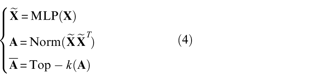
In this study, UGW monitoring signals
As illustrated in Figure 1, the proposed DA-RGCN comprises three modules: the feature extractor
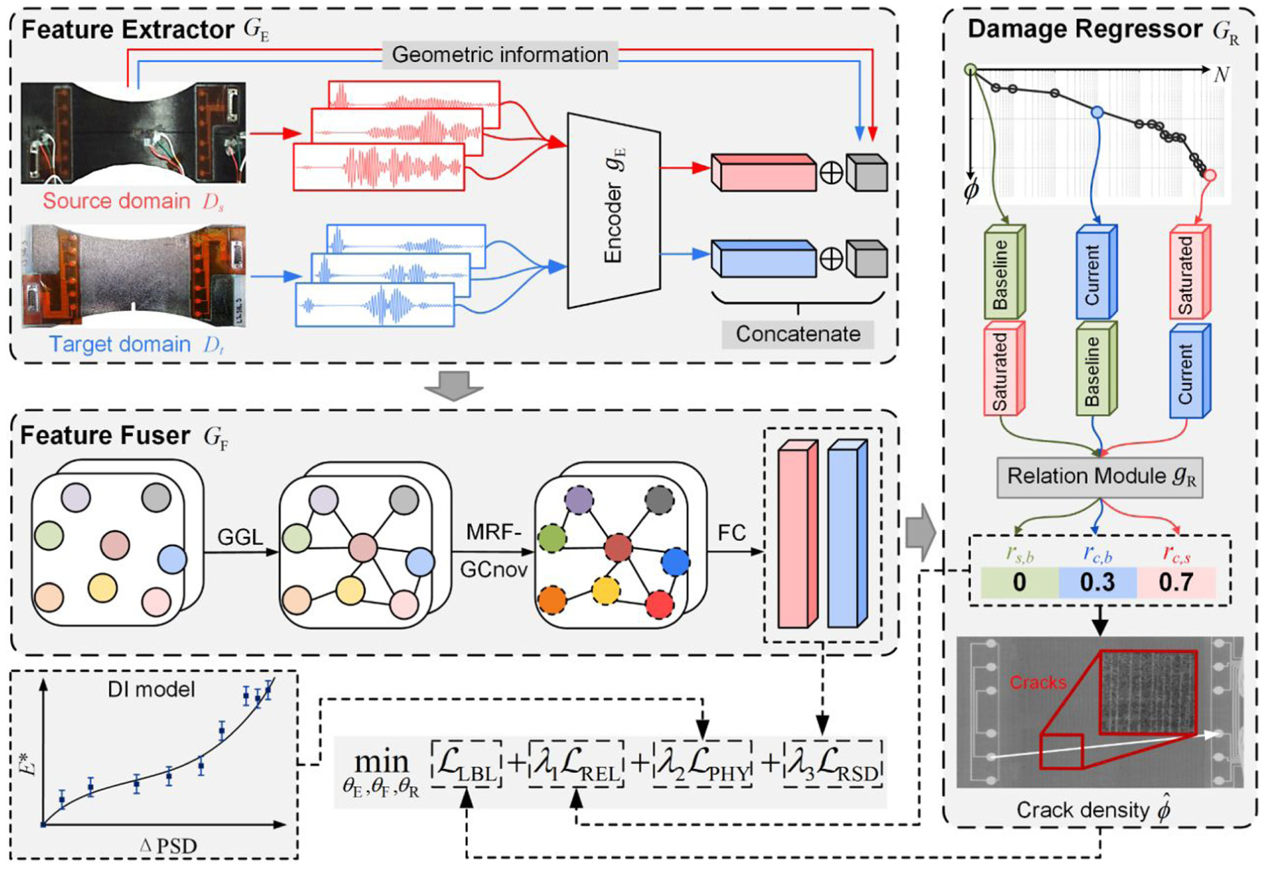
Overall framework of the proposed approach for crack identification in composite structures.
Temporal convolutional layer for feature encoding
Analyzing the temporal variations of actuation wave packets in actuator and sensor signals is crucial for understanding guided wave propagation patterns. To this end, we designed an encoder
As illustrated in Figure 2(a), the design of
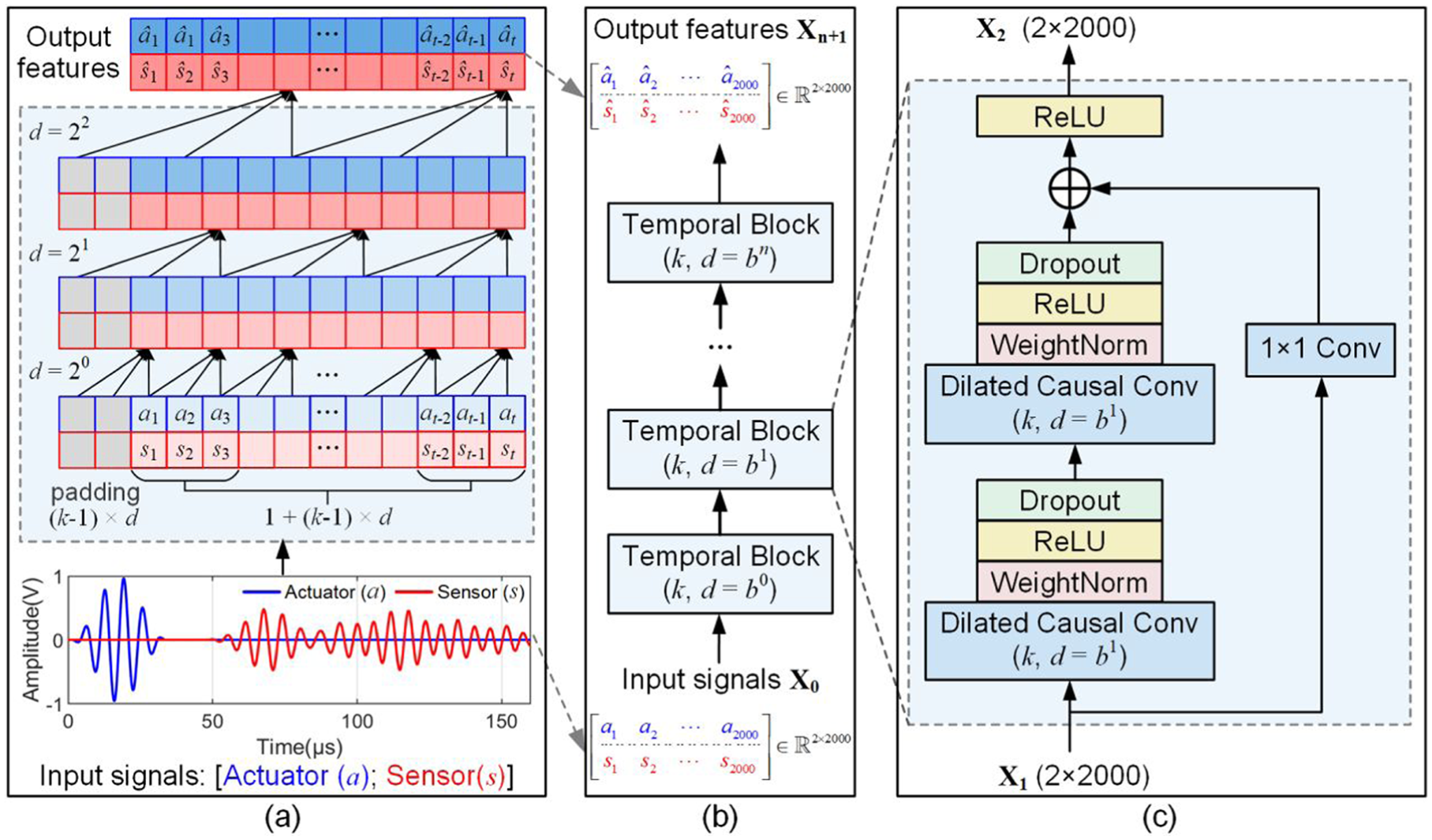
Illustration of the encoder
The sequential structure of the encoder

where
Here,

where
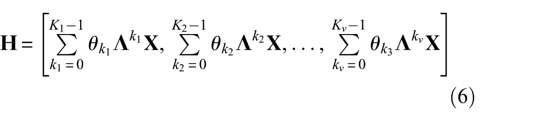
Multireceptive field graph convolutional layer for feature fusion
Consider a batch of guided wave signals
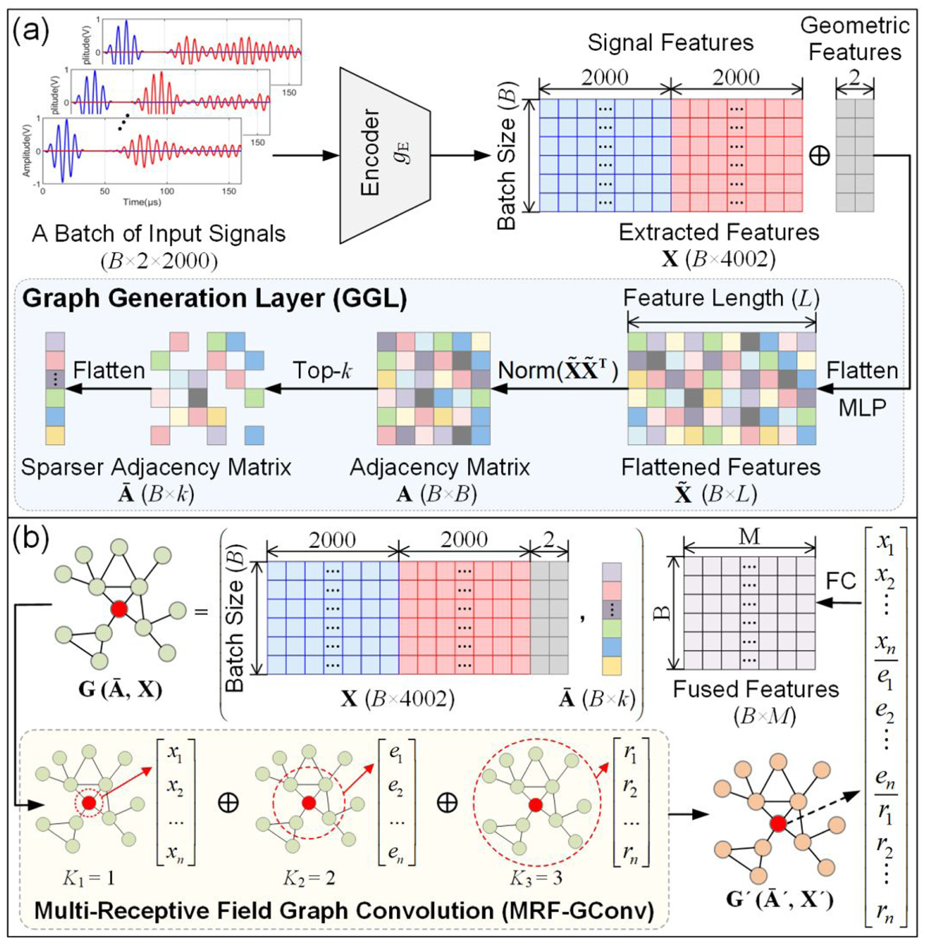
Illustration of the feature fusion between signal features and geometric features within the feature fuser
Specifically, the extracted features
where
Through these steps, we construct a graph

where
The characteristics of graph CNN generally lead to a large number of parameters. Therefore, we need to analyze the computational complexity of the proposed MRF-GConv to provide a theoretical reference for balancing accuracy and efficiency. For each ChebConv layer in MRF-GConv, the time complexity consists of the product of the adjacency matrix and the feature matrix, along with the product of the weights and the feature matrix, with complexities of
Relation layer for crack density identification
To capture the degradation trend of composite structures, the damage regressor
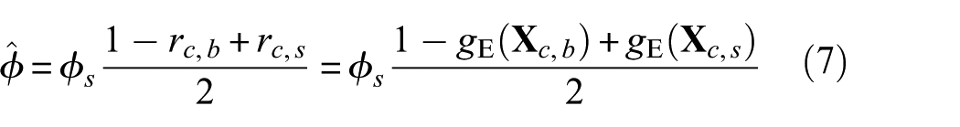
where
where b, c, and s represent the damage-free baseline state (crack density = 0), the current state, and the saturation state (maximum crack density =
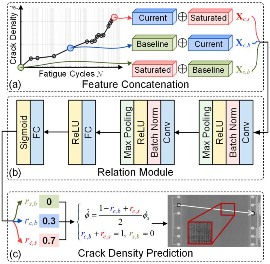
Illustration of the damage regressor
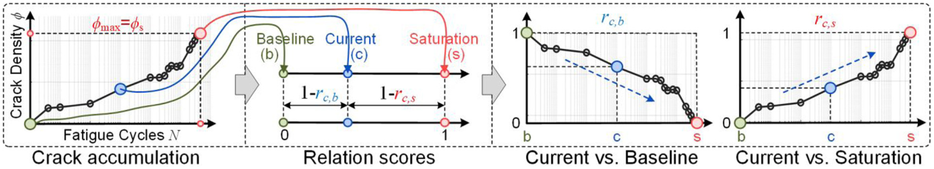
Normalize the crack accumulation process to the range [0, 1] using the relation scores
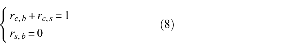
Specifically, for the crack accumulation process along a given path, we regard the baseline state (b) and saturation state (s) as the starting and ending points of damage evolution, respectively. When fatigue loading is applied to the structure, the current state (c) gradually transitions from the baseline state toward the saturation state. In this process, we can use
In Figure 4(c), we use relation scores of 0, 0.3, and 0.7 as examples, which satisfy the constraints defined in Equation 8. Based on these relation scores, we then apply Equation 7 to calculate the final predicted crack density. In this case, crack densities varying across different ranges were converted to relation scores within the range of [0, 1]. On the one hand, the aligned label space mitigates the influence of channel distance differences on labels, enabling DA-RGCN to capture a representative degradation trend from various angles and lengths of paths. On the other hand, the degradation trends of different composite structures are constrained to the same range, facilitating the transfer of learned identification knowledge from the source domain to the target domain.
Design of the loss function
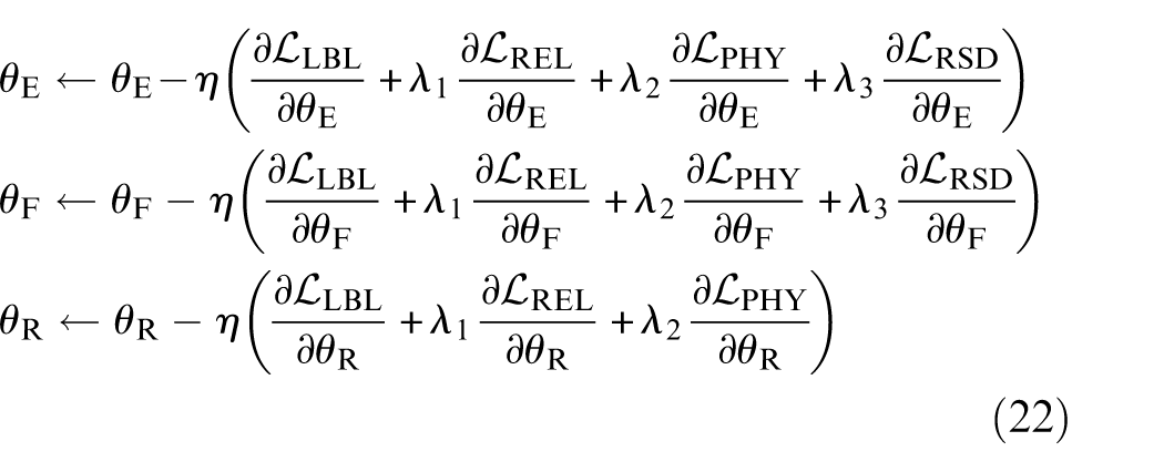
The optimization goal of the proposed DA-RGCN can be expressed as follows in Equation (9):
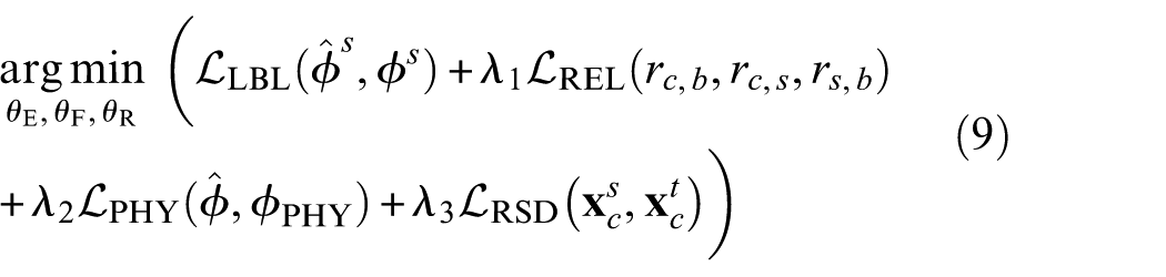
where
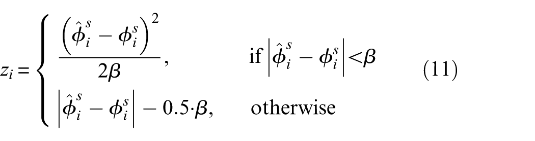
Specifically, the identification errors

where
where
According to the constraints defined in Equation (8) regarding the relation scores, the relational error
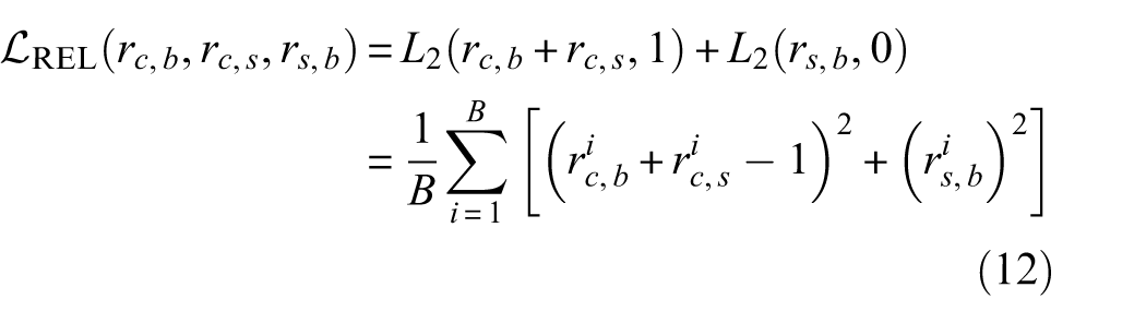
where
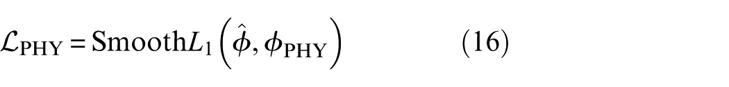
The identification error relative to the physical model,
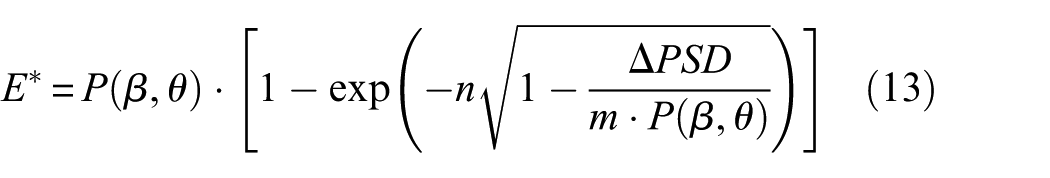
where
where
The identification result of DA-RGCN must align with
For domain adaptation between the source representation space

where
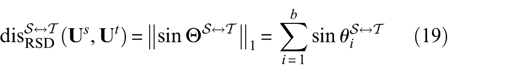
As illustrated in Figure 6, the two b-dimensional subspaces
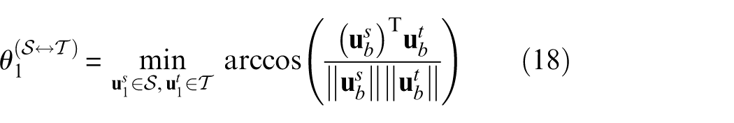
where
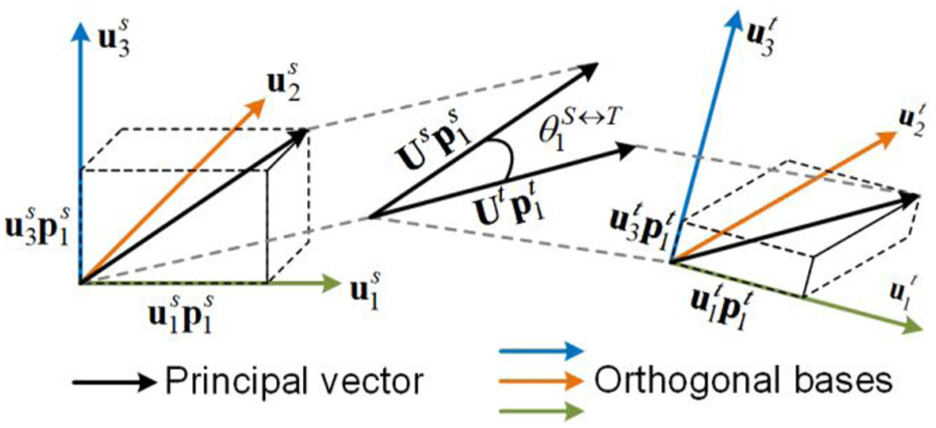
The calculation process of principal angles.
Additionally, since the domains differ in the importance rankings of orthogonal bases, an extra constraint is needed to ensure that orthogonal bases representing similar semantic information are reasonably matched. To maintain the geometric structure of feature representations, a mismatch penalization (BMP) term is introduced, expressed as Equation (20):

where

Let
Case study
Introduction to datasets
To validate the proposed DA-RGCN for diagnosing transverse cracks in composite structures, CFRP data set collected during accelerated aging experiments of composite laminates were used. 54 Both sides of the laminates were fixed on the Materials Test System (MTS) machine during the experiments, simulating the progressive degradation of laminates by applying controlled cyclic loadings. The two types of laminates in the experiments, made from Torayca T700G unidirectional carbon-prepreg material with dogbone geometry, are shown in Figure 7(a). The sizes of unnotched and notched specimens are 15.24 cm × 25.4 cm and 15.24 cm × 20.32 cm, respectively. A sensor network consisting of two sets of six PZT sensors SMART Layer®55 was attached to the specimen, utilizing 6 × 6 = 36 paths to periodically excite and collect guided-wave signals in a pitch-catch configuration. This sensing configuration is consistent with practical guided-wave monitoring systems for composite structures. In engineering applications, the PZT transducers can be surface-bonded or embedded into the laminate, and the monitoring data are acquired by actively exciting one transducer and recording the responses at the remaining sensors through a multichannel acquisition unit. In the present study, signals were collected periodically during fatigue testing and were paired with X-ray-based crack observations to establish the reference labels. The approach is attractive for field deployment because PZT networks are lightweight, low-cost, and capable of monitoring relatively large areas with limited hardware. Although long-term sensor durability, environmental variability, and measurement noise remain important practical concerns, these issues can be alleviated by protective packaging, regular calibration, and robust signal processing. Additionally, three strain rosettes were affixed at the ends and center of each specimen to monitor structural stiffness degradation under fatigue loading. The detailed layup configurations of these specimens are shown in Figure 7(b): (a) Unnotched: Layup 1 [02/904]S; (b) Notched: Layup 3 [902/45/-45]2S. The layup direction and sequence of unidirectional plies determine the anisotropic characteristics of CFRP composite structures, leading to significant differences in wave velocities across various propagation directions. Furthermore, strong and anisotropic damping effects from the fiber and matrix constituents can alter the excitability and attenuation of guided waves. 56 As a result, even signals collected under the same crack damage condition can exhibit noticeable discrepancies when sourced from different paths, posing challenges for crack identification in composite structures.
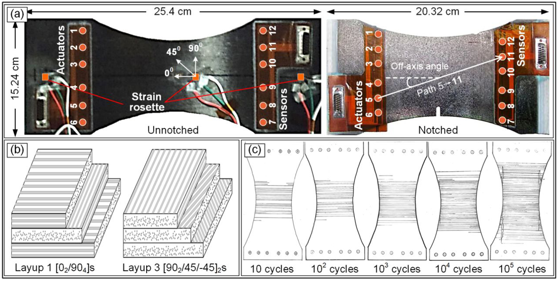
Overview of accelerated aging experiments: (a) two types of specimens with an attached sensor network and strain rosettes, (b) structural details of the two layups, and (c) X-ray images collected under varying fatigue loading cycles.
To assess the actual level of damage growth, X-ray images were periodically taken to serve as the ground truth. As depicted in Figure 7(c), several hand-drawn images provided by the dataset publisher were considered the ground truth for damage progression after fatigue loading. Transverse matrix cracks were induced in the middle of the laminate and accumulated under fatigue loading until their density saturated and delamination occurred. The crack density

where
As shown in Figure 8, the sensor signals collected from paths 3–9 exhibit energy scattering and phase shifts as crack density increases. The propagation of guided waves in the laminate is influenced by its layup. The first and second wave packets in signals from T19F, T21F, and T22F (Figure 8(b) to (d)) are quite similar, as they all have the same structure, Layup 1. In contrast, the first wave packet in the signals from L3S13, which has a Layup 3 structure, arrives earlier and has a narrower width, as shown in Figure 8(a). Moreover, differences in signals can occur even among specimens with identical structures. This variability arises from the differing layouts of the sensor network in each specimen, which can alter the off-axis angle
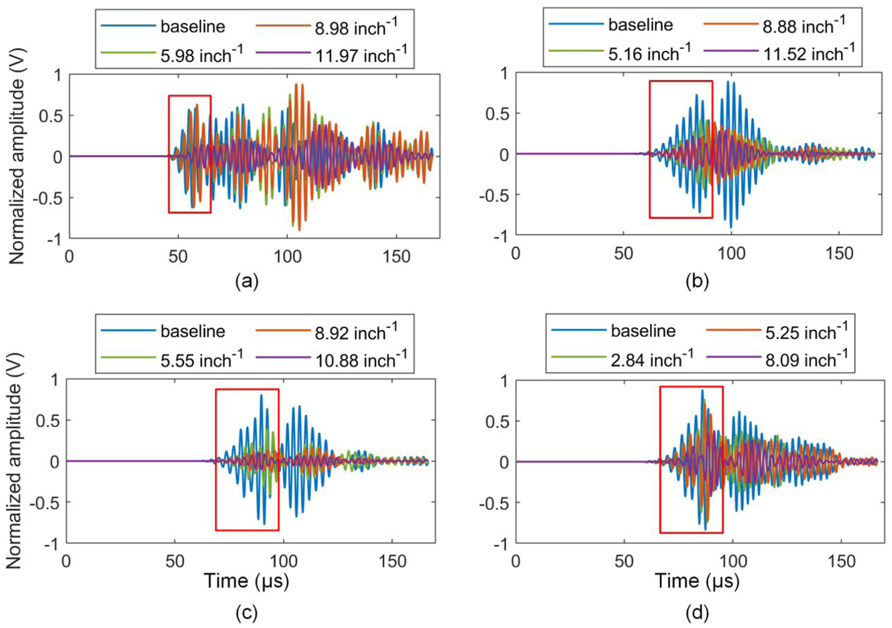
UGW signals collected from the path 3–9 in four different specimens as crack density increased. Layup 3: (a) L3S13; Layup 1: (b) T19F, (c) T21F, and (d) T22F.
Preprocessing of UGW signals
In the accelerated aging experiments, UGW signals were collected using ScanScentry data actuation and acquisition hardware with various input voltages
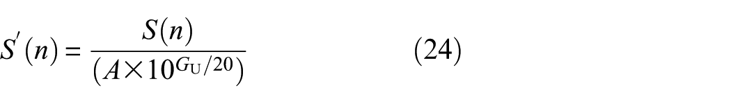
Each pair of sensor and actuator signals was then organized into data instances with a shape of (2, 2000), respectively. To avoid interference from delamination in crack identification, only data before reaching saturated crack densities were selected. The selected data and the corresponding crack density labels were grouped into four datasets, representing four distinct domains in this study. Details of the four selected datasets, including specimen type, fatigue-cycle range, and the number of retained instances, are summarized in Table 1.
Details of four specimens used for crack density identification across different structures.
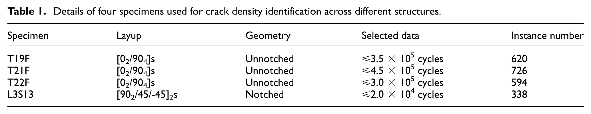
In total, the final dataset used in this study contains 2278 guided-wave instances collected from four CFRP specimens, namely T19F, T21F, T22F, and L3S13. The three unnotched specimens were selected because they share the same layup and capture the natural initiation and accumulation of matrix cracks throughout fatigue loading, which makes them suitable for learning the progressive degradation trend under relatively consistent structural conditions. The notched specimen L3S13 was further included to evaluate transferability under a more challenging setting, as it differs in both stacking sequence and geometry while still exhibiting matrix-cracking-dominated damage evolution in the early stage. This combination of specimens enables the proposed method to be examined under both intra-layup and cross-structure distribution shifts.
To ensure data quality and reproducibility, only monitoring paths whose direct actuator-sensor trajectories remained fully within the laminate boundaries were retained for analysis. This criterion helps preserve clearly identifiable direct-wave packets and reduces interference from boundary reflections, which is essential for stable feature extraction and fair comparison across different specimens. In addition, only signals collected under traction-free conditions and before delamination-dominated stages were used, so that the labels primarily reflect the evolution of transverse matrix cracking rather than mixed damage mechanisms.
Hyperparameter tuning
The detailed parameter settings for the DA-RGCN model are provided in Table 2. The model comprises three main modules, as illustrated in Figure 1, and includes a total of 3,665,249 trainable parameters. Let
Parameter configurations for the proposed DA-RGCN model.
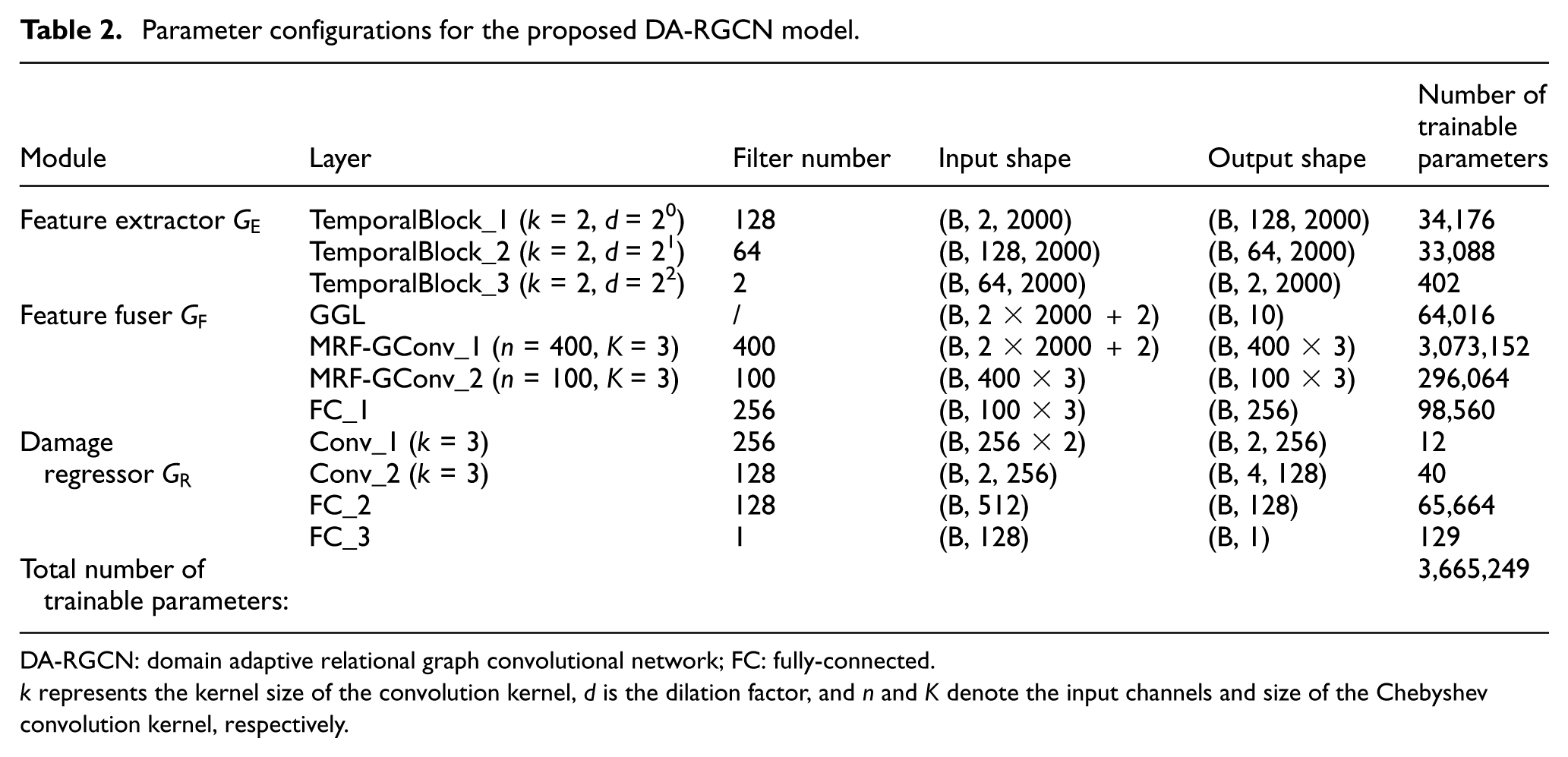
DA-RGCN: domain adaptive relational graph convolutional network; FC: fully-connected.
Before training, three hyperparameters
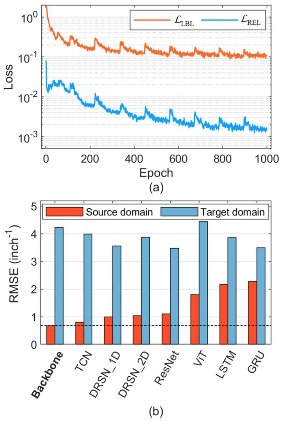
Performance of the DA-RGCN backbone network in the transfer task TT19F→T21F: (a) both losses decrease synchronously during training and (b) comparison with other deep learning networks for crack density identification.
However, even though T19F and T21F share the same layup, differences in data distribution prevent the direct transfer of all methods to the target domain, resulting in high identification errors, as shown in Figure 9(b). To address this, we employed a cosine annealing learning rate decay strategy during model training, with
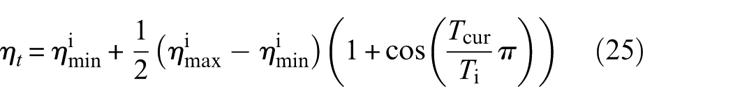
where
Specifically,
Training of DA-RGCN
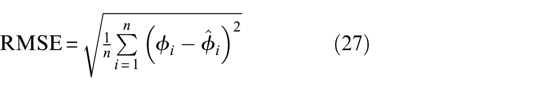
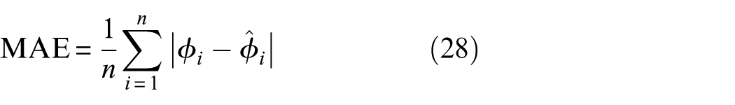
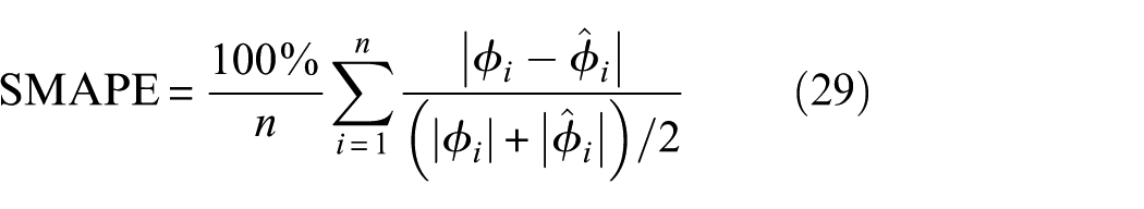
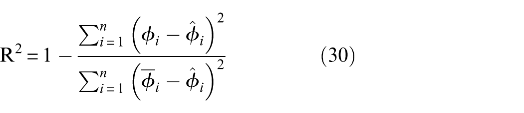
With all hyperparameters established, nine transfer tasks were designed to train and test the DA-RGCN model, as outlined in Table 3, so that its transferability could be examined across both similar specimens and structurally distinct laminates. Six transfer tasks between T19F, T21F, and T21F aim to verify whether the learned identification knowledge can be transferred among composite structures with different sensor layouts. Additionally, the remaining transfer tasks from T19F, T21F, and T21F to L3S13 are intended to assess the feasibility of transferring damage diagnosis knowledge between composite structures with distinct plane geometries, both notched and unnotched. To evaluate the performance of the well-trained model in the target domain, we employed a set of metrics that address absolute accuracy, outlier sensitivity, and explanatory power. The RMSE and MAE serve as primary measures, providing error estimates in the original units of crack density for better physical interpretability. Specifically, MAE tracks the average error magnitude, while RMSE highlights large deviations to test robustness against catastrophic failures. For relative error, we adopted symmetric mean absolute percentage error (SMAPE) instead of mean absolute percentage error (MAPE) to maintain numerical stability when dealing with near-zero ground truth values. Furthermore, the coefficient of determination (R2) was used to measure the proportion of explained variance, enabling standardized comparisons across different models. By integrating these metrics, we facilitate a multidimensional assessment of accuracy and reliability under challenging conditions. For
Performance of DA-RGCN on nine transfer tasks.
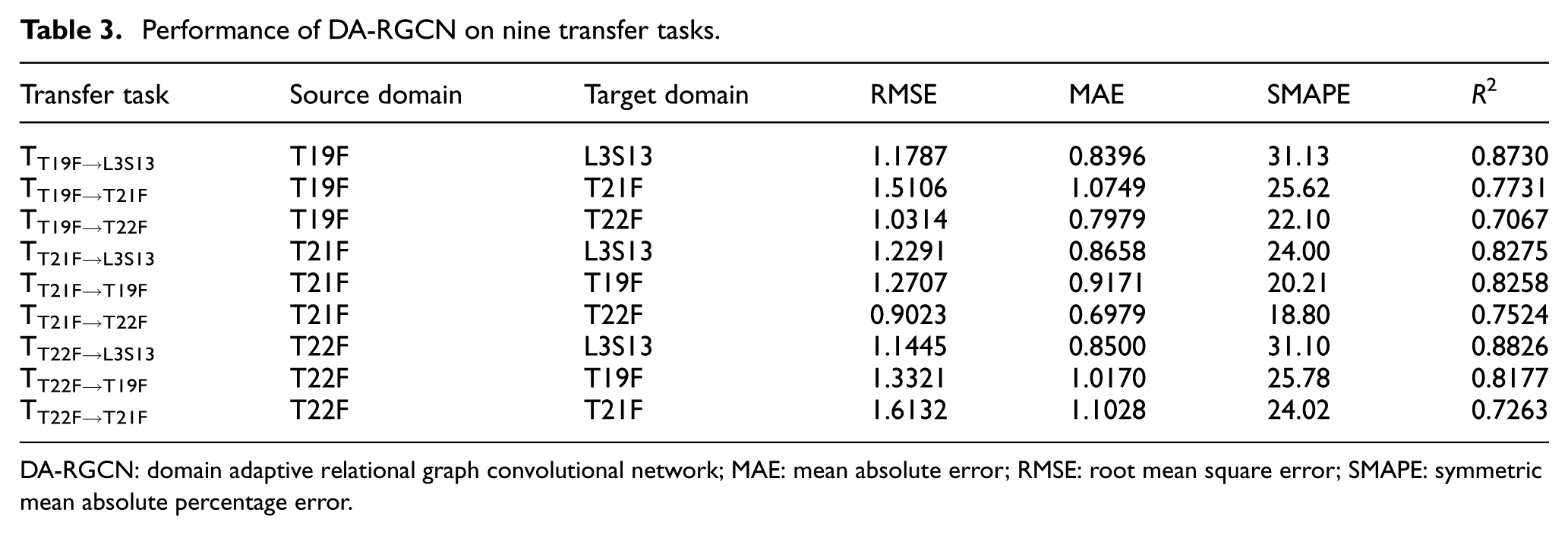
DA-RGCN: domain adaptive relational graph convolutional network; MAE: mean absolute error; RMSE: root mean square error; SMAPE: symmetric mean absolute percentage error.
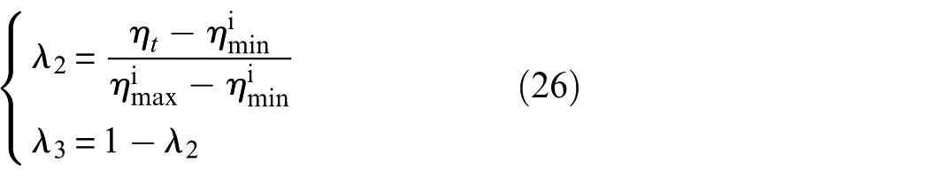
Using the training of TT19F→L3S13 as an example, all labeled data from the source domain and 50% of unlabeled data from the target domain were used to train the model. The remaining 50% of the target domain were utilized to assess the transfer performance of the well-trained model. Additionally, two data groups representing the baseline and saturation states were selected from each specimen to calculate the relation score. For a given path, the baseline state corresponds to the guided wave signals collected at cycle 0, while the saturation state corresponds to signals collected when the crack density is at its maximum. Since there are 36 different paths in the sensor network, each data group contain 36 guided wave signals. The batch size was set to 32, and the learning rate was dynamically adjusted within the range of [2 × 10⁻⁴, 2 × 10⁻⁷] according to Equation (25). Figure 10 presents the trajectories of the learning rate, loss function components, and test results. During the 1000-epoch training process, each learning rate restart enables the model to escape local optima, facilitating a renewed downward trend in the loss curves toward a more global minimum. The fluctuation amplitude of these curves is governed by the weight decay strategy defined in Equation (26). As the weighting coefficient
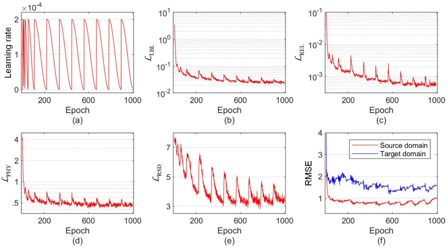
Training process of the proposed DA-RGCN: (a) learning rate curve, (b) source domain identification error
Transferable crack identification across domains
The remaining transfer tasks were conducted in the same settings, and the corresponding results for two specimens are presented in Table 3. The generalization ability of the proposed model beyond the primary training specimens was evaluated through nine transfer tasks covering both within-layup and cross-structure scenarios. In particular, TT19F→L3S13, TT21F→L3S13, and TT22F→L3S13 serve as direct case studies for cross-structural transfer, because the target specimen differs from the source specimens in both geometry and layup. Consistent predictive performance on these tasks indicates that the proposed model does not merely fit specimen-specific signal patterns, but is able to preserve crack-related knowledge under substantial distribution shifts.
For example, in the transfer tasks TT19F→T22F and TT21F→T22F, where T22F served as the target domain, the DA-RGCN achieved identification errors of 1.0314 and 0.9023, respectively. When T21F was the target domain in the tasks TT19F→T21F and TT22F→T21F, the identification errors were 1.5106 and 1.6132, respectively. The difference in performances across these transfer tasks can be attributed primarily to the shorter degradation trend time range learned from T22F (≤3.0 × 10⁵ cycles) compared to the other two specimens (T19F: ≤3.5 × 10⁵ cycles, T21F: ≤4.5 × 10⁵ cycles). The absence of this critical identification knowledge diminished model performance in the target domains. Assuming similar cracks accumulation across the three specimens, T19F and T21F provided data with higher loading cycles, allowing the DA-RGCN to learn a degradation trend over a longer time range than T22F. Consequently, when transferring to T22F, the degradation trend learned from the source domain encompassed the identification knowledge required for the target domain, leading to improved damage diagnosis performance. Conversely, when the target domain contains data with higher loading cycles than the source domain, the identification knowledge needed exceeds what the model learned, resulting in a decline in performance, albeit remaining acceptable.
For L3S13, which has a completely different layup compared to the other three specimens, the DA-RGCN achieved identification errors (RMSE) of 1.1787, 1.2291, and 1.1445 in TT19F→L3S13, TT21F→L3S13, TT22F→L3S13, respectively. Theoretically, variations in the layup direction and thickness of the samples will alter the propagation characteristics of guided waves within the structure, leading to inconsistencies in the data distribution of guided wave signals collected from the two samples. This typically results in a significant reduction in the performance of conventional data-driven models that rely on the assumption of independent and identically distributed training and testing data. In contrast, the proposed DA-RGCN learns the transition trends of a given signal from a baseline state to a saturated state by calculating relation scores based on metric learning. Additionally, it employs transfer learning to facilitate the transfer and reuse of damage diagnosis knowledge within a fixed range of [0, 1] for different samples. Consequently, the average identification error (RMSE) for DA-RGCN from T specimens (T19F, T21F, T22F) to L3S13 is 1.1841. The predicted results from these well-trained models in the target domain are illustrated in Figure 11.
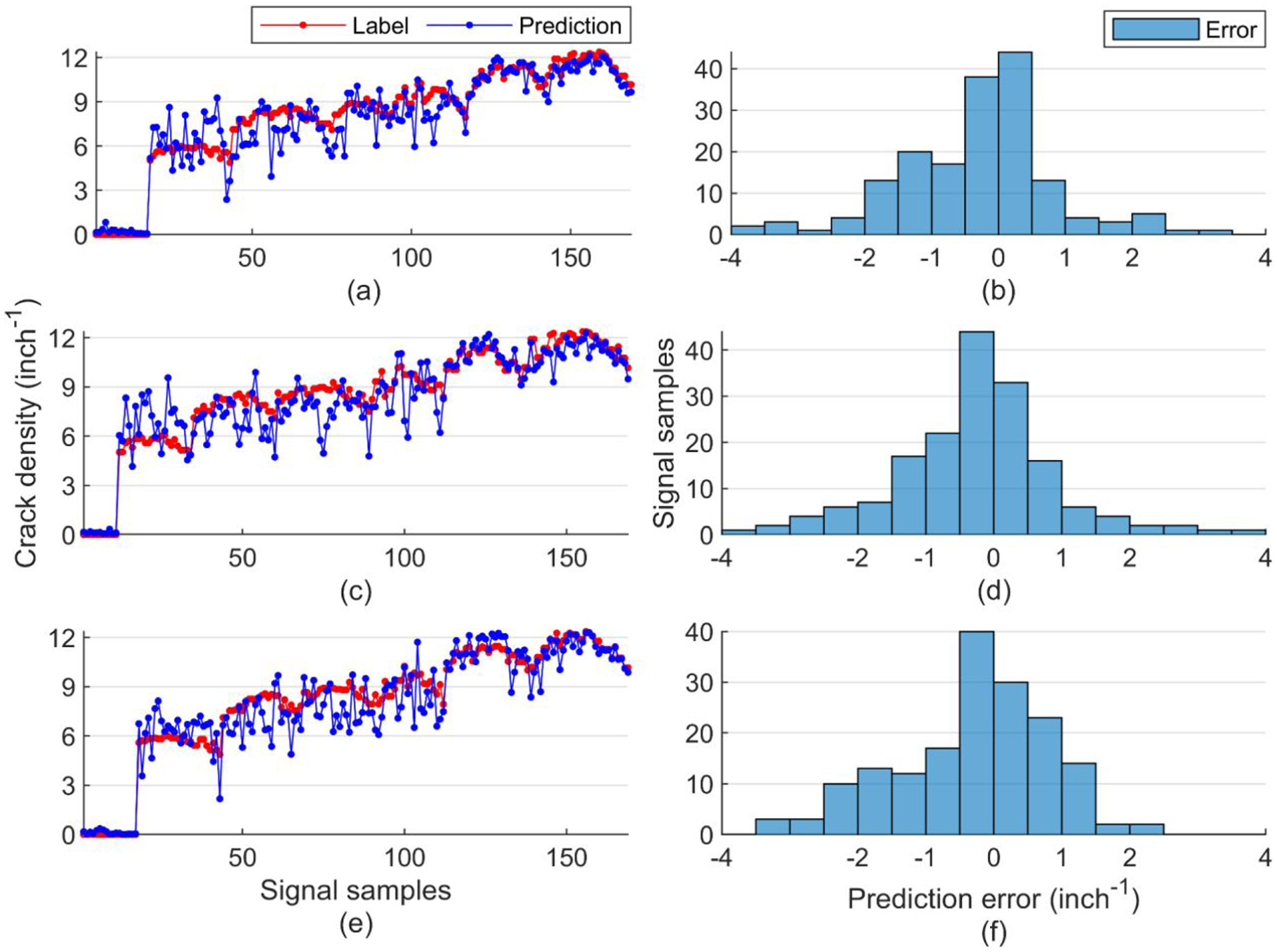
Identification results for three transfer tasks in cross-structural crack diagnosis. Curves of predicted crack densities and corresponding identification errors: (a)–(b) TT19F→L3S13, (c)–(d) TT21F→L3S13, and (e)–(f) TT22F→L3S13.
Compared to the actual crack density labels, the identification errors for both the baseline and saturation state are minimal. As the value of crack density increases, the model’s identification error gradually decreases, reaching zero when the crack density is saturated. Statistics presented in Figure 11 indicate that most identification errors fall within the range of [−1, 1], which aligns with the RMSE calculated in Table 3. Overall, these results demonstrate that the proposed DA-RGCN effectively achieves high precision in the transfer of damage diagnosis across composite structures with different layups.
Ablation experiments
To further analyze the contributions of each component in the proposed DA-RGCN, two groups of ablation experiments were designed to assess the effects of network architecture and loss function on model performance in the target domain. In the first group of experiments, the damage regressor
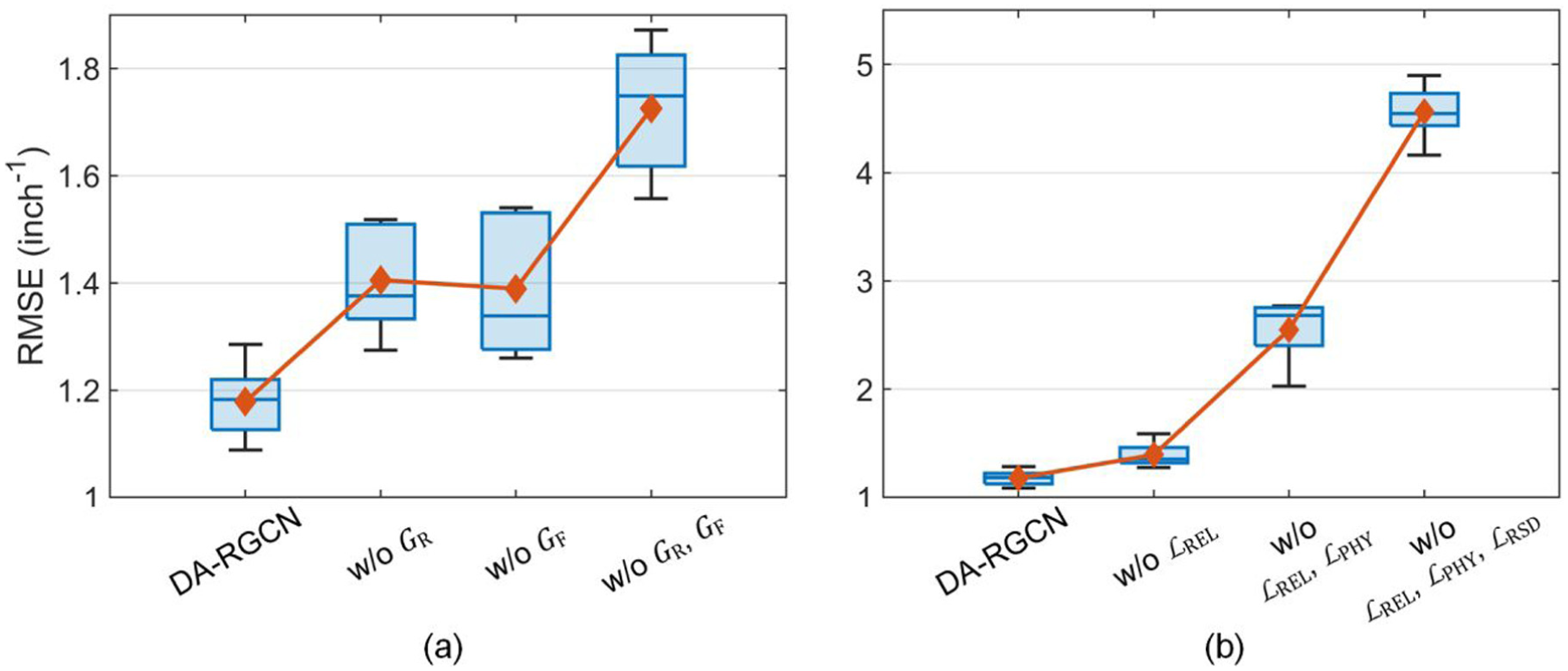
Results of the ablation experiments on the (a) network architecture and (b) loss function.
In the second group of ablation experiments, all terms except the label loss
Comparison with popular methods
We also compare the proposed DA-RGCN with other deep transfer learning-based approaches in task TT19→L3S13, which utilize domain adaptation, domain adversarial techniques, or a combination of both to facilitate transfer. Approaches such as the dynamic adversarial adaptation network, deep subdomain adaption network, and multiple domain adaptive and adversarial network require label categories to partition the feature representation space into corresponding subspaces. To address this, we introduced a soft label to divide the crack density label into ten intervals. Each interval was treated as a distinct category, allowing transfer learning to be implemented in these models. Specifically, we utilized a transfer learning toolbox 62 to implement these methods, which incorporates various popular transfer learning models using the PyTorch framework and provides an efficient and unified training and inference process. Unlike the default image-based input, we modified the ResNet-50 backbone to accept time-series data used in this study. For fairness, all models were trained with the Adam optimizer with a learning rate of 0.001 for 1000 epochs, using early stopping based on the target-domain RMSE. To achieve optimal performance on the target-domain test set, the transfer-loss weight was tuned within the range [0.5, 1.0, 10]. We evaluated the model performance using multiple criteria, including regression metrics to assess predictive accuracy, as well as computational efficiency indicators such as parameters, floating point operations (FLOPs), and inference time. As shown in Table 4, all approaches except the proposed method yielded an identification error RMSE exceeding 4, which is unacceptable for damage diagnosis in the target domain. Unlike discrete category labels used in the classification tasks, the continuous crack density labels hinder these approaches from effectively aligning the joint probability distribution of the source and the target domain, resulting in poor performance. In contrast, the proposed method incorporates three unique modules for crack density regression and employs a specially designed loss function to facilitate the transfer of identification knowledge. Consequently, the proposed DA-RGCN achieves superior performance in the target domain, with a minimum identification error RMSE of 1.1787. Although DA-RGCN does not have a parameter scale advantage, its specially designed modules for extracting damage-related features and the tailored loss function for transfer regression tasks enable it to maximize the model’s nonlinear fitting capabilities, achieving higher predictive performance with fewer parameters. Moreover, these newly introduced modules are highly efficient, resulting in no significant increase in model parameters or FLOPs. Compared with other transfer learning methods, DA-RGCN still maintains millisecond-level inference speed, which is advantageous for deployment in engineering applications.
Comparison of the proposed method with other deep transfer learning approaches.
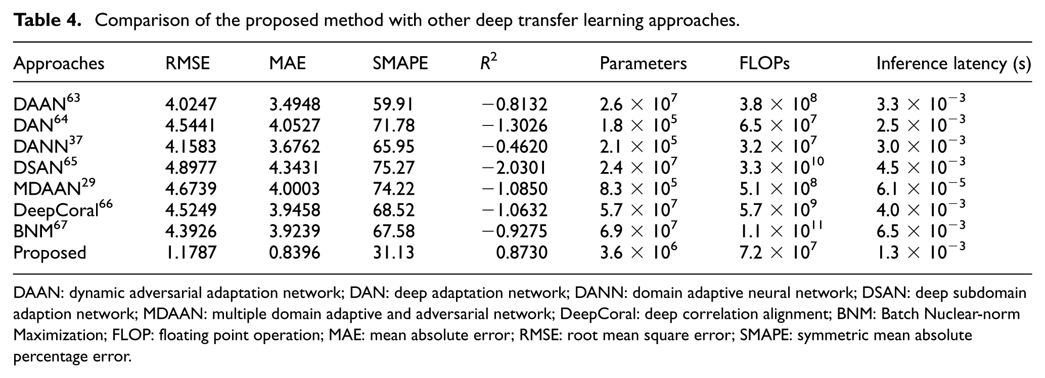
DAAN: dynamic adversarial adaptation network; DAN: deep adaptation network; DANN: domain adaptive neural network; DSAN: deep subdomain adaption network; MDAAN: multiple domain adaptive and adversarial network; DeepCoral: deep correlation alignment; BNM: Batch Nuclear-norm Maximization; FLOP: floating point operation; MAE: mean absolute error; RMSE: root mean square error; SMAPE: symmetric mean absolute percentage error.
Considering that the DA-RGCN leverages the DI model to accelerate convergence in the early stage of training, it is essential to compare its performance with that of the DI model used directly for predicting data in the target domain. Figure 13 illustrates the crack density results from the traditional DI model (marked in red), our proposed DA-RGCN method (marked in blue), and the ground truth data (marked in black) across the corresponding fatigue cycles. For each fatigue cycle, nine paths with varying off-axis angle
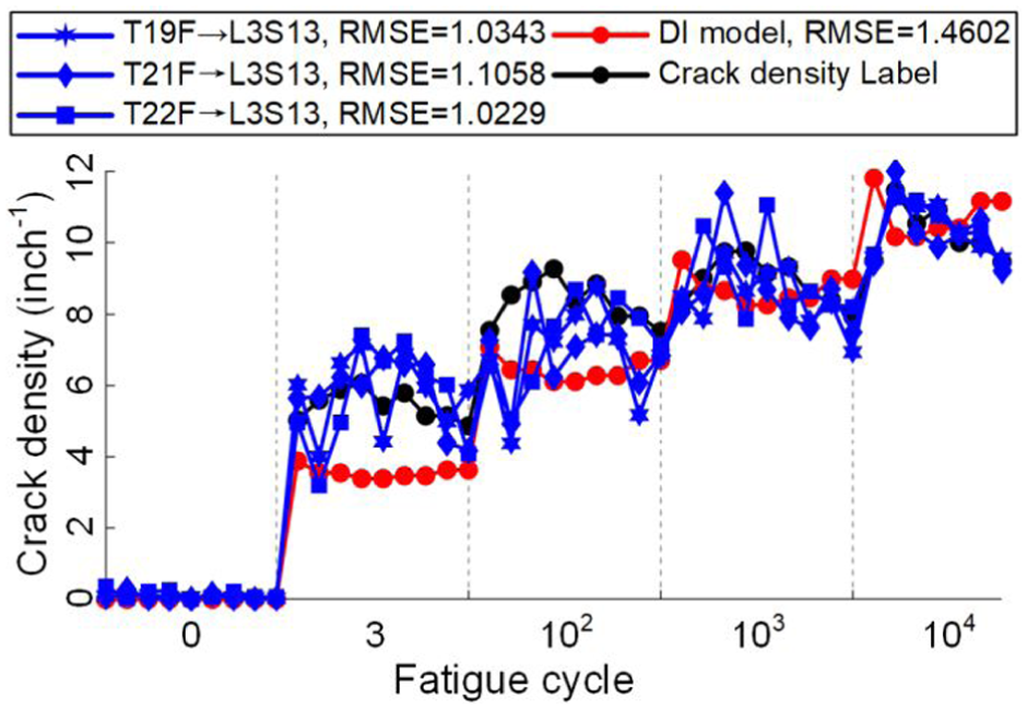
Identification results from DA-RGCN and the DI model. For each fatigue cycle, nine paths with varying off-axis angles
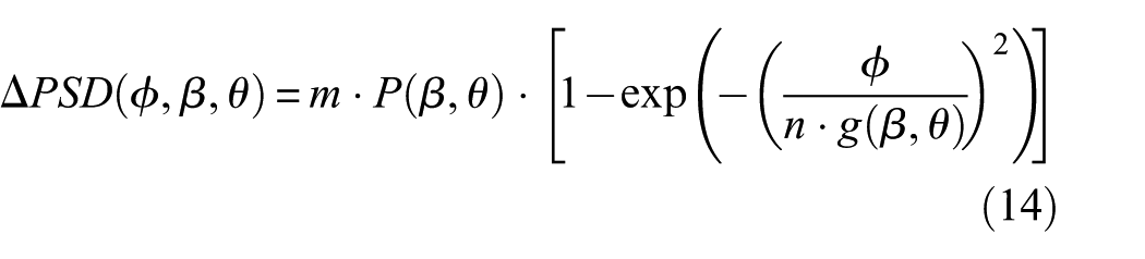
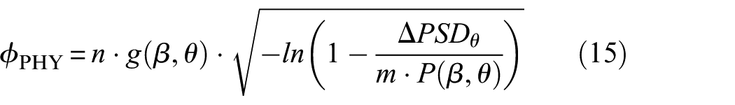
To address these challenges, the conventional DI model employs ΔPSD to indicate crack growth, constructing statistical models based on signals from two specific paths. Parameters
In contrast, our proposed DA-RGCN model utilizes a TCN-based backbone network to analyze signal changes throughout the propagation process and automatically extract high-dimensional features related to cracks. These embedded features provide a comprehensive representation of crack accumulation compared to the ΔPSD-based approach, enabling better utilization of the signal. To mitigate the impact of path differences, we define the baseline state (signals with no cracks) and the saturated state (signals with maximum crack density) as the lower and upper bounds of crack growth. By comparing the similarity between the extracted features and these boundaries, we calculate relation scores
The predicted crack density for each path in L3S13, as determined by the DA-RGCN, is shown in Figure 14. The hand-drawn horizontal lines in the images represent the transverse matrix cracks recorded during the accelerated aging experiments, while the lines connecting the actuators and sensors indicate the 36 paths in the sensor network. As the number of fatigue cycles increased, cracks extended from the center of the laminate outward, resulting in an increased crack density along each path. Additionally, delamination damage was initiated at the notch and progressed inward within the laminate. For paths with varying off-axis angles and lengths, the DA-RGCN accurately predicts crack density, maintaining the identification error within the range of [−1, 1].
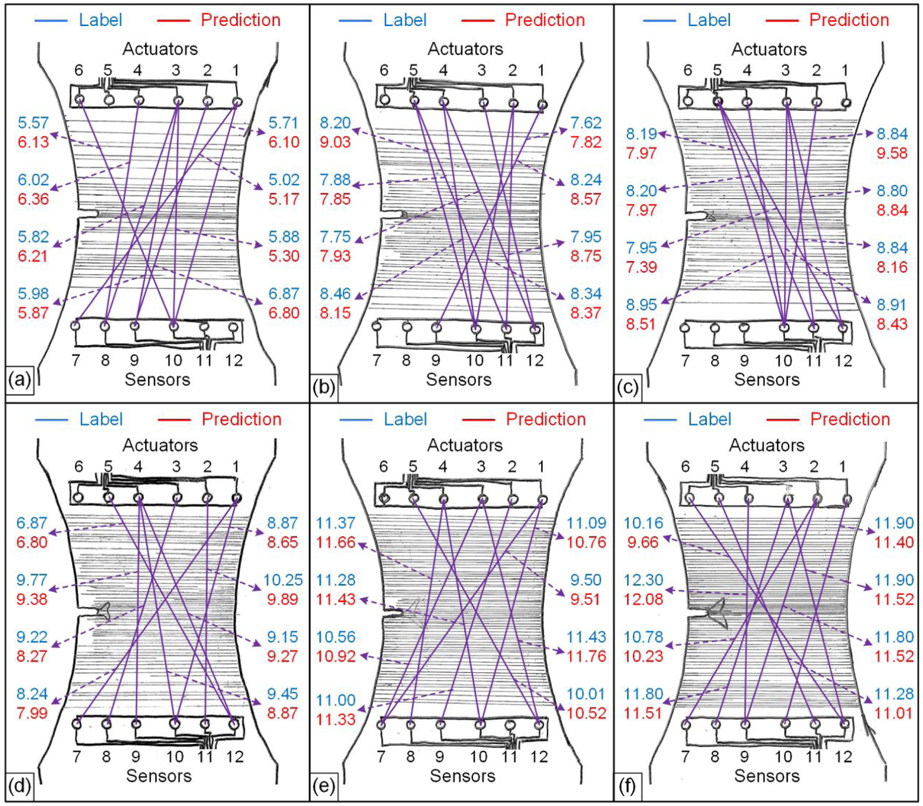
Visualization of crack density identification results for L3S13 by DA-RGCN: (a) cycle = 3, (b) cycle = 20, (c) cycle = 100, (d) cycle = 1000, (e) cycle = 10,000, and (f) cycle = 20,000.
Conclusion
In this study, we propose a DA-RGCN model for predicting the crack density in composite structures, which is capable of being transferred to other structures with varying layups and two-dimensional geometrics. To learn robust feature representation from UGW monitoring signals, a TCN-based feature extractor is employed to extract damage-related features from both actuator and sensor signals. These features are then transformed into graphs in the feature fuser, where geometric information of the sensor network is fused with the extracted signal features. By calculating the relation scores between the fused features and the baseline and saturation states, we align the label spaces of different specimens to predict the crack density in the damage regressor. Additionally, the DI model and RSD loss are incorporated into the loss function to guide model training and ensure domain invariance in the fused features. A series of transfer tasks were conducted to validate the effectiveness of the proposed method for cross-structural damage diagnosis. Two groups of ablation experiments were also performed to assess the impact of these components on model performance. Ultimately, the model achieved an average RMSE of 1.1841 in crack density identification across structures, outperforming other deep transfer learning approaches. The limitation of this study is that the proposed method still requires unlabeled data from the target domain for effective domain adaptation. In some real-world applications, obtaining target domain data from new laminates for training may be challenging, which can hinder the transferability of the crack identification model. To address this limitation, future work will focus on further reducing the reliance of the crack identification model on data from new laminates, and augmenting the training dataset with data from other sources, such as the finite element simulation. Additionally, extending the proposed method to structures with more complex geometries, such as those that possess stiffeners and holes, could further enhance its applicability.
Footnotes
Funding
The authors disclosed receipt of the following financial support for the research, authorship, and/or publication of this article: This research is supported by the National Natural Science Foundation of China under Grant No. 52405164 and the New Faculty Startup Fund from City University of Hong Kong under Grant No. 9610612.
Declaration of conflicting interests
The authors declared no potential conflicts of interest with respect to the research, authorship, and/or publication of this article.