
Abstract
There are vast numbers of light-emitting diode (LED) luminaires to choose from, but not all LED luminaires perform reliably. More than half of the input electrical power to a LED luminaire is wasted in the form of heat. Heat management is the one of the most critical issues faced by LED luminaire designers. The long term reliability of a LED luminaire is mainly dependent on the junction temperature of the LEDs. Hence, accurate junction temperature information during luminaire operation is critical for monitoring and assessing the health of the luminaire. In practice, it is extremely difficult to measure the junction temperature of LEDs in modern day luminaires. With the optical system and heat sink surrounding the tiny LED, measurement of junction temperature with direct methods like infrared cameras and thermocouples becomes more complex. This paper explores the possibility of monitoring and measuring the junction temperature of LEDs in a luminaire by making use of the strong correlation between the forward voltage drop at the LED junction and the temperature of that junction. Results of thermal investigations of a LED downlight are presented. The results suggest that the inherent forward voltage/ junction temperature dependency of LEDs can be used to measure and monitor LED junction temperature in a luminaire under operational conditions.
1. Introduction
Though light-emitting diode (LED) lighting is relatively new concept, LED luminaires have been operating in many indoor and outdoor installations for more than five years. LED luminaires are fully compliant with the EU Restriction of Hazardous Substances Directive and other environmental regulations and deliver up to 80% energy savings over conventional lighting technologies. LED devices have a very long service life. This useful service life of LEDs can provide added value to any lighting installation if the electronic circuitry including controls and drivers used in LED luminaires are as reliable as the LEDs. The components in a LED luminaire must be able to survive the unforgiving conditions of the environments in which they are installed. LED luminaires have only been introduced into the global market over the last few years so there is inadequate data available that can address the life expectancy of the LED device or the power supply electronics.
Street lighting, parking area lighting and downlighting are a few of the niche applications where many manufacturers have released LED-based lighting products. These products are in direct competition with traditional lighting products. The photometric performance and useful operating life of LED luminaires vary with application area and operating environment. With vast number of LED luminaires to choose from, not all LED luminaires perform reliably. The LED as a separate item can be of good quality but the way in which the LED is integrated into a luminaire is critical to the success of the LED luminaire.
LED luminaires are popular for their energy efficiency when compared to their traditional counterparts but nearly 60–70% of input electrical power to a LED luminaire is wasted in the form of heat. Heat management of the LED luminaire is the one of the most critical issues for luminaire designers. Improper heat management during operation increases the temperature inside the luminaire which will, in turn, increase the LED junction temperature. This will negatively impact light output and reduce the service life of the LEDs in the luminaire.
The junction temperature is dependent on the drive current provided to the LED and the environment in which the LED is operated. Desired light output and service life can be ensured for a LED luminaire if the p–n junction of the LEDs is maintained within a specified temperature band and the heat generated is dissipated away from the p–n junction to the heat management system of the luminaire and from there to ambient air. The accurate estimation of the useful operating life and long term reliability of a LED luminaire therefore depends on the availability of accurate junction temperature information during luminaire operation.
The junction temperature is significant for other reasons. The internal quantum efficiency of LEDs directly depends on the junction temperature. High junction temperatures will lead to higher device temperature which will lead to deterioration of the encapsulate material. It therefore becomes vital to know the operating junction temperature of the LEDs in the luminaire.
Junction temperature is extremely difficult to measure in practice. With the optical system and heat sink surrounding the tiny LED, measurement of junction temperature with direct methods like infrared cameras and thermocouples becomes more complex. Advances in semiconductor technology are further helping LED manufacturers to shrink the size of the LED, thereby making it impossible to directly measure their junction temperature. However, the LED junction has an inherent forward voltage/ junction temperature dependency and this relation is linear under normal operating environments up to 70–100℃. Nonlinearity in this relation exists at higher temperatures which can be experimentally determined. Making use of this theory, the LED junction itself can be used as a temperature sensor and LED luminaire designers can reliably measure and monitor the junction temperature in a LED luminaire.
This paper explores the possibility of monitoring and measuring the junction temperature of LEDs in a luminaire by making use of the strong correlation between the forward voltage drop of a LED junction and the temperature of that junction.
2. Background
Markets today, especially in developing countries, are flooded with cheap LED lighting products that are of extremely poor quality. Most of these cheap LED lighting products show signs of common failures that arise from poor design, substandard component quality and poor manufacturing practices. LED lighting products that fail to function properly are causing market spoilage, wherein consumers have become more and more cautious and at times chosen traditional lighting products over LED lighting products. One of the reasons for poor quality LED lighting products in the market is the lack of knowledge amongst luminaire manufacturers on quality checks and verification of the LED luminaire design.
With ready availability of LEDs in the market, assembling LED lighting products is a fairly easy job. A low investment requirement and readily available simple technology create a lot of business opportunities for low skilled individuals from rural and urban areas in developing countries. One can easily start a home-based LED lighting manufacturing unit in India for under US$100. Most LED lighting manufacturers in the unorganised sector in developing countries do not have proper test facilities and will have to pay huge fees for testing their luminaires in government or accredited private laboratories to get certified. With few sophisticated test facilities to hand, manufacturers have to wait for months to get their products tested before releasing them onto the market. Most of the time, manufacturers do not want to face these hindrances and hence release their products onto the market without testing. Such products come into the market with false information about their performance on their packs. This type of market spoilage is a grave concern for the growth of the LED lighting market.
Another reason for market spoilage of LED lighting products is counterfeit copies of the popular LED lighting products of reputable companies but made from substandard components. Most of the time LED manufacturers try to replicate the performance of popular LED products by assembling off-the-shelf components of different companies. Most of the times there will not be a proper match amongst the different components used to make the LED luminaire, e.g. the LED module will be powered by an improper driver or the LED module may be mounted on a heat sink of improper heat dissipation capability. If a LED luminaire is made, it should be tested in-house first and, based on in-house test results, be refined and tested in accredited laboratories before release onto the market. The objective of this work is to propose a methodology for luminaire designers to verify one of the critical aspects of a LED luminaire, the thermal management system.
Light output from LEDs will reduce and their device efficiency will go down if they are operated at temperatures above the maximum junction temperature recommended by the manufacturers. Elevated junction temperatures can severely affect the useful lifetime and reliability of LEDs and that of the luminaire. Most of the LED failure mechanisms reported in literature are related to thermal issues. 1 LED luminaires are strictly regulated for safety and quality standards; therefore it is the duty of the LED luminaire designer to guarantee that the LEDs do not overheat.
LED manufacturers recommend measuring solder point temperature of LEDs in order to estimate the junction temperature.2,3 However, this method can only be employed for LEDs and multi-LED arrays on a printed circuit board (PCB). It cannot be employed for LEDs in a market-ready luminaire. In a market-ready luminaire there is no direct access to the solder point or the PCBs. The only measuring point is the power supply leads from the LED light engine emerging through the heat sink connected to the driver module.
When estimating the junction temperature by measuring solder point temperature, the thermal resistance between the junction and solder point needs to be found from the manufacturer’s datasheet. Junction temperature then can be estimated using solder point temperature, thermal resistance from junction to solder point and power dissipated in the path from the junction to solder point. However, application of the solder point temperature measurement method is difficult when thermal investigations are done on a randomly picked luminaire from the market. In this case, there may not be adequate data available about the luminaire, the LEDs or the thermal resistance information (junction to solder point).
To perform this junction temperature measurement, the luminaire needs to be disassembled and then the solder point temperature is measured, but the value of the measurements is reduced as the tests are done on parts of a luminaire rather than a complete luminaire. Further, solder point temperature is measured using a thermocouple. This must involve proper contact between the solder point and the thermocouple otherwise a systematic error is introduced which will affect the accuracy of the measurements.
The methodology proposed in this paper can easily be applied to any randomly picked LED luminaire for measuring and monitoring its junction temperature. This methodology does not require any data regarding the luminaire, LED package, solder point temperature or thermal resistances for estimating junction temperature. This test can be done on an integrated luminaire without having to disassemble it.
Diodes are extensively used as temperature sensors in electronic circuits. Diodes exhibit a linear relationship between changes in their forward voltage to changes in their junction temperature. Diodes are the cheapest and reasonably accurate devices amongst all temperature sensors and are best suited as temperature sensors in low cost and low precision applications. The fundamentals of a diode’s forward voltage have to be studied and understood in order to take steps to make accurate temperature measurements using them.
The current flowing through the ideal semiconductor diode when it is forward biased for positive applied voltages is approximated and given by the simplified equations below,
4


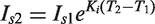
In equation (1), I is the current flowing through the diode. The reverse saturation current is I s . This is junction temperature dependent. VF is the diode’s forward voltage. VT is the thermal voltage of the diode given by equation (2), ‘n’ is the ideality factor (a constant which has value from 1 to 2). In equation (2), ‘k’ is Boltzmann’s constant, Tj is the junction temperature and ‘q’ is the electron charge. The effect of temperature on the reverse saturation current can be quantified using equation (3). This makes it possible to calculate the change in Is at two temperatures T1 and T2 (where T2 > T1). The constant ‘Ki’ in equation (3) is expressed in terms ‘/℃’ and is dependent on the type of semiconductor material.
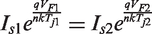
For a constant current ‘I’ flowing through the diode, when the junction is maintained at two different temperatures Tj1 and Tj2 (where Tj2 > Tj1), we have current ‘I’ expressed as equation (4) when junction temperature is Tj1 with forward voltage VF1 and reverse saturation current Is1. Similarly, equation (5) expresses current ‘I’ when junction temperature is Tj2 with forward voltage VF2 and reverse saturation current Is2 (where VF1 > VF2).


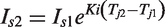
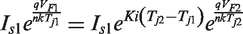
From equation (3), Is2 can be expressed in terms of Is1 as shown in equation (6),
Equating equations (4) and (5) as the current ‘I’ is maintained constant at two different junction temperatures Tj1 and Tj2,
After cancelling out Is1 from both left-hand and right-hand sides and taking the natural logarithm on both sides and after rearranging, equation (7) can be expressed as follows,
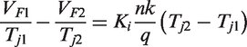
It can be seen from equation (8) that the relation between forward voltage VF and junction temperature Tj is linear under constant diode current. If the corresponding forward voltages and junction temperatures are plotted against each other a descending straight line is obtained as shown in Figure 1. Sometimes the VF–Tj relationship may be slightly non-linear however generally not enough to considerably influence thermal data. From the linear relationship it can be observed that a change in junction temperature produces a corresponding change in forward voltage with a constant correlation factor ‘K’ given by (Tj2–Tj1)/(VF1−VF2), expressed in terms of ‘℃/mV’. The ‘K’ factor is highly dependent on the diode current ‘I’. This linear VF–Tj relation can be used to measure junction temperature by measuring forward voltage under constant current conditions.
Linear relationship between forward voltage (VF) and junction temperature (Tj) under constant diode current.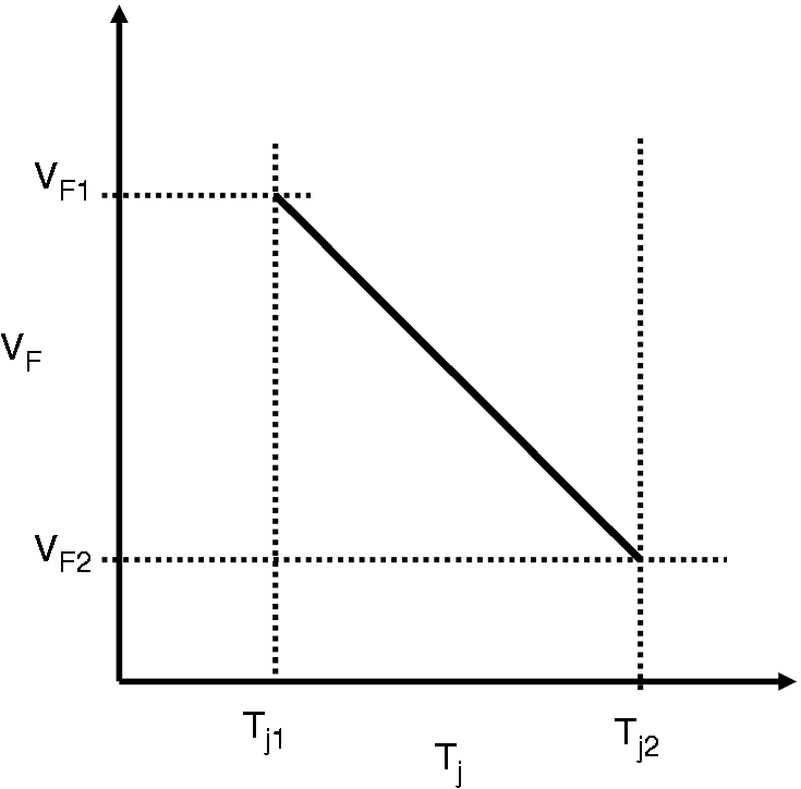
3. Objective
The objective of this work is to propose a methodology for luminaire designers to estimate the junction temperature of LEDs in a luminaire. The proposed method makes use of the VF–Tj linear relation under constant current conditions to estimate the operating junction temperature of LEDs. By recording the change in forward voltage under constant current conditions, the change in junction temperature can be estimated. The same principle can be extended to estimate junction temperature by measuring forward voltage under a given diode current. The total forward voltage VF-total across a LED string where ‘N’ LEDs are connected in series is given by equation (9),
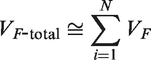
Hence the proposed method can be easily adopted for any kind of LED luminaire, no matter whether LEDs are arranged in series or parallel or in a combination of series-parallel strings.
4. Experiment
4.1 Method
The proposed method is based on forward voltage measurements for estimating junction temperature which has been widely used by researchers and manufacturers.5–7 The method adopted is illustrated in Figure 2. In this method, a LED luminaire is placed inside a temperature controlled oven. The temperature of the oven is initially set at 25℃. The LED luminaire is allowed to attain thermal equilibrium at this temperature which may take up to 30 minutes. Once thermal equilibrium is attained it can be assumed that the junctions of the LEDs inside the luminaire are also at 25℃, the same temperature as that of the oven. The next step is to pass a short duration current pulse through the LED luminaire and measure the forward voltage drop. The LED luminaire is injected with a small magnitude (around 1 mA) current pulse for a duration of less than 1 ms or with a pulse train of duty cycle 0.1% (on period of less than 1 ms). This ensures that the current pulse will not introduce self-heating of the junction and it does not affect Tj. With the low duty cycle, heat dissipated from LED can be ignored so the oven temperature can be assumed to be the same as the LED junction temperature. The same procedure must be repeated at different temperatures to obtain the VF–Tj relationship.
Experimental setup to obtain the VF–Tj relationship of a LED downlight.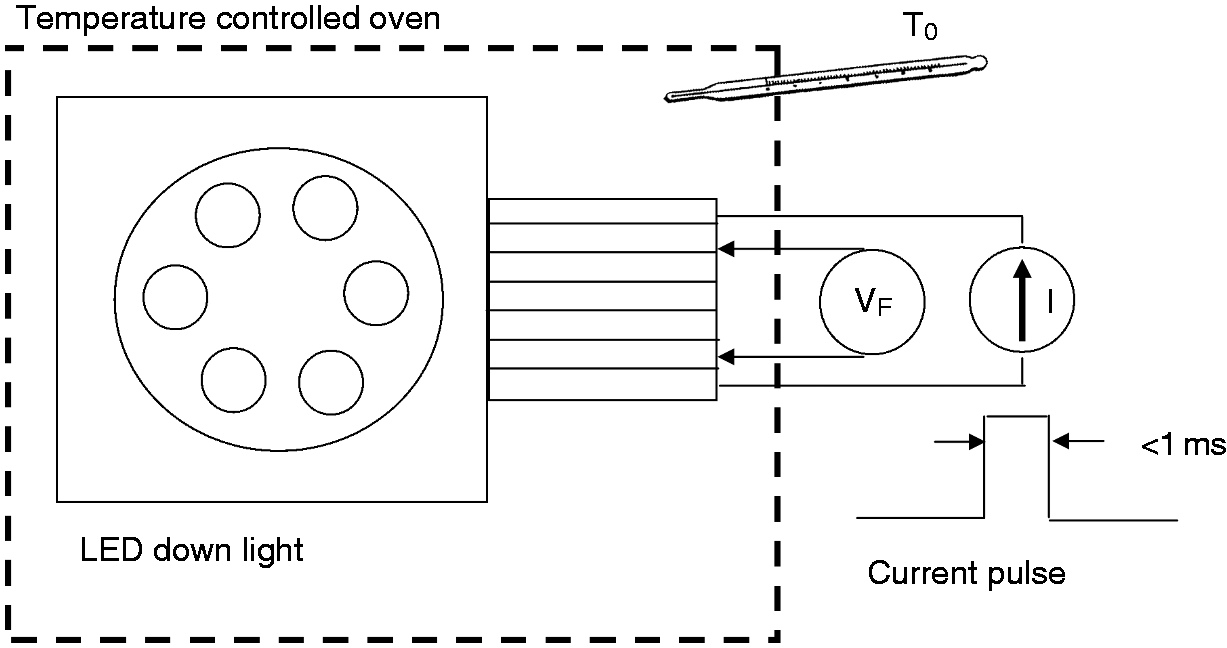
Selection of current magnitude is critical for this type of measurement. No one value of measurement current is appropriate for all LED luminaires. An important tip to select current levels is that the current levels should be small enough to avoid self heating of the LED junction and large enough to differentiate the signal from the noise. In this case, the selection of measurement current is based on the rated parameters of the LED luminaire. The current levels that were chosen in this study ranged from 5 mA to 270 mA. This covers a wide measurement range. The lower current level is the level at which the LEDs in the luminaire just start conducting and the upper level is the rated drive current of the luminaire under normal operating conditions. Higher current levels and long duration pulses may distort the results by heating the junction. This can be overcome by ensuring a very short duration current pulse and a very fast forward voltage measurement.
Measurement of VF is done under different oven temperatures for different currents. The oven temperatures were changed from 10℃ to 100℃ in steps of 10℃. There is an interval of 1 hour between successive measurements, giving enough time for the LED luminaire to reach thermal equilibrium under the new oven temperature. The measurements were repeated five times and mean values are used in all calculations and plots.
4.2 Measurement details
Properties of the LED downlight tested.
The rated lumen output of the LED luminaire was measured using absolute photometry on a manually operated C-type goniophotometer using a Konica-Minolta Chromameter CL200 as a photodetector. Care was taken to ensure that the burning position of the luminaire was unchanged and the speed of rotation of the equipment had negligible influence on the thermal performance and thermal equilibrium of the luminaire. Air temperature around the luminaire was maintained in the range 24–26℃ with adequate care taken to ensure proper shielding of the luminaire from direct radiation. Air flow around the luminaire was maintained at less than 0.2 m/s. The heat conduction through luminaire support structures was ensured to be negligible and had minimal impact on the thermal equilibrium of the luminaire and on its performance.
The AC power supply produced a sinewave with ≤3% distortion of the fundamental frequency. The voltage regulation was maintained at ±0.2% of the rated value. No seasoning of LED luminaire was done prior to testing. The steady state of the LED luminaire was decided by considering the lumen output and input electrical power when the variation of last three readings over a period of 45 minutes, measured 15 minutes apart, was less than 0.5%. Meters used for measuring electrical parameters like AC current, voltage, power and DC current and voltage had calibration uncertainties of
5. Results
This section discusses the results of applying the forward voltage method to estimate junction temperature of LEDs in a downlight. Recessed downlights constitute a wide range of luminaires. Downlights are typically installed above the ceiling and emit light through an opening. Downlights are common in both commercial and domestic applications; they provide both ambient and accent illumination. With billions of incandescent lamp-based downlights installed worldwide, there is potential for substantial energy savings by retrofitting traditional downlights with high-efficacy LED lighting products.
The LED luminaire used for this study is shown in Figure 3. It is a LED based downlight picked from a local lighting store. It is one of the several LED lighting products available in the market which come without appropriate labelling and certifications from government agencies or accredited laboratories. When a sample is requested from a manufacturer for testing, they will provide the best samples for testing, while releasing cheaper, lower quality units for sale in the market. LED downlights worldwide have stringent installation requirements to prevent excessive temperature rise of the luminaire and driver so as to prevent ignition of combustible materials. Hence, it becomes essential to measure and monitor temperature rise in a LED downlight. Junction temperature is one of the important parameters which directly give indication about the health of the thermal management system.
The LED downlight with an external driver selected for junction temperature measurement.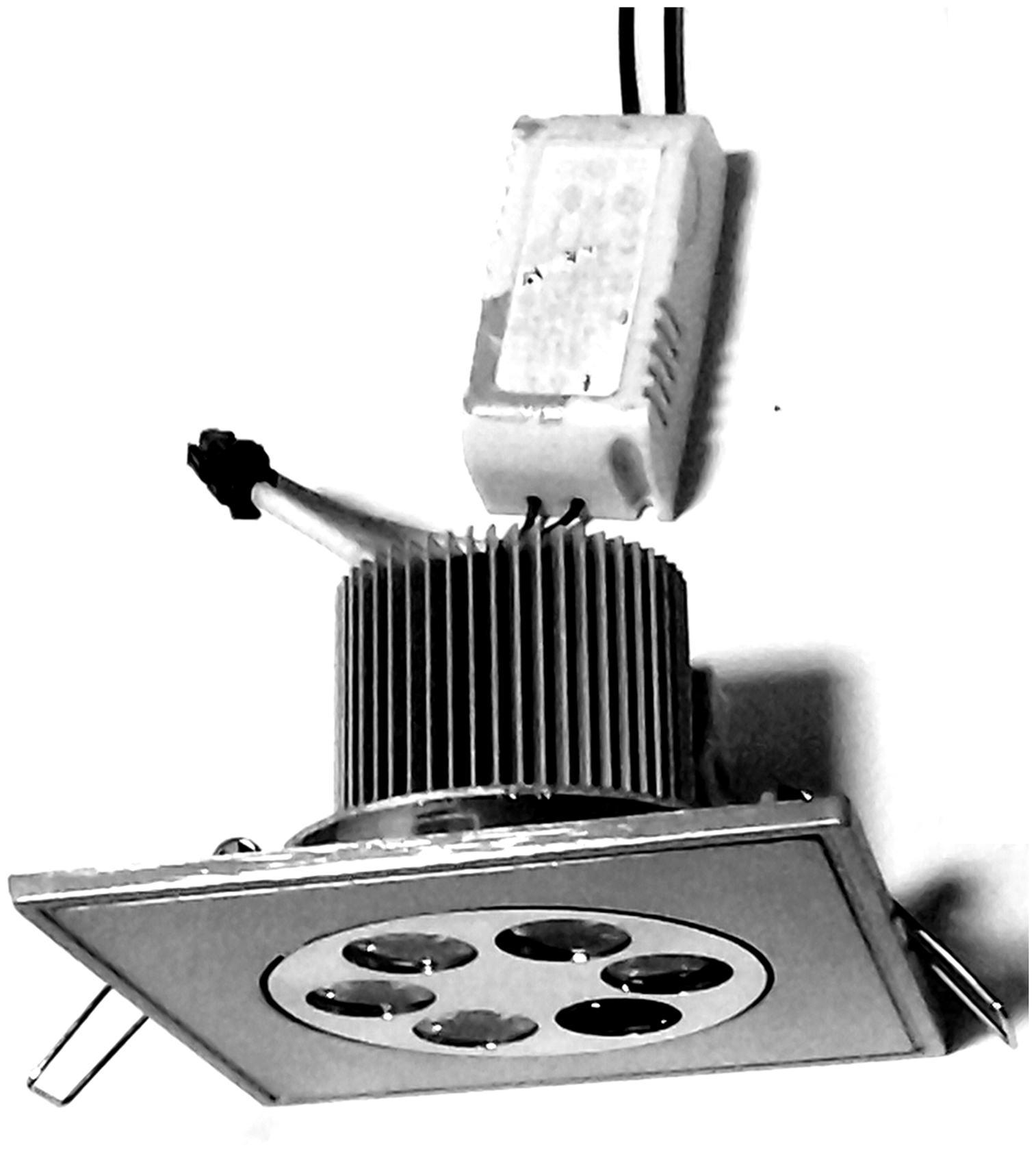
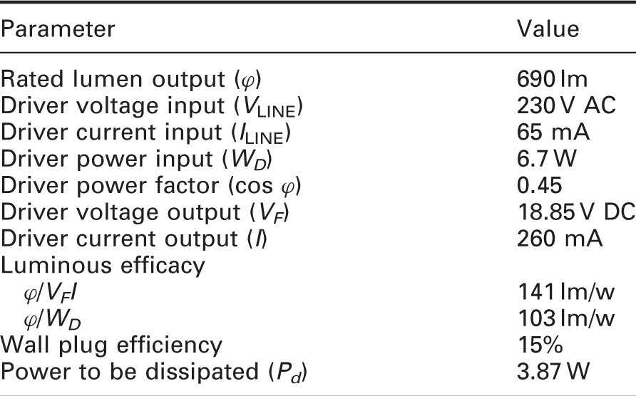
The luminaire selected for testing has six high power LEDs, whose make and rated parameters are not known. Each LED is covered with a clear plastic lens. A large finned heat sink surrounds the back of the luminaire body. The driver is external to the luminaire body. The operating parameters were recorded and tabulated (Table 1). These operating parameters were recorded after five measurement rounds and their mean is presented in the table.
The rated lumen output of the LED luminaire is 690 lumens. The wall plug efficiency (WPE) is calculated by considering the driver power input (WD) of 6.7 W. This will take into account the driver losses in calculating the overall WPE of the luminaire. WPE is also referred to as ‘overall luminous efficiency’ when expressed in dimensionless form (for example, as a fraction of the maximum possible luminous efficacy). Considering the luminous efficacy of 103 lm/W for a driver input power of WD = 6.7 W, the WPE was calculated as 15% (i.e. WPE = ϕ/WD = 103/683).
The power to be dissipated Pd is calculated by considering the losses at the luminaire. The driver is external to the luminaire, any heat generated at the driver will have minimal impact on the LED luminaire’s performance and its thermal equilibrium. An approximate value of luminous efficiency of the LED luminaire is calculated by considering the luminous efficacy of the LED luminaire without considering driver losses (i.e. ϕ/VFI = 141 lm/W). The corresponding luminous efficiency is approximately 21% and hence the power to be dissipated by the thermal management system is 79% multiplied by product of VF and I that is approximately equal to 3.87 W.
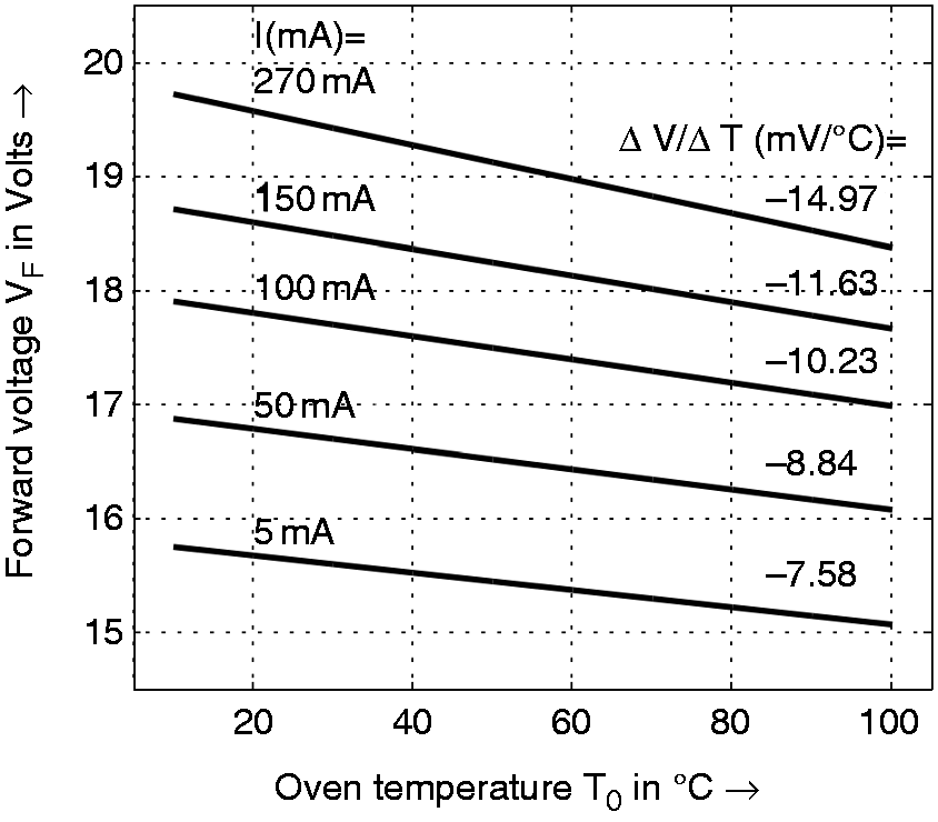
Experimental results shown in Figure 4 establish the relation between forward voltage VF of the LED downlight and the oven temperature. The heat generated by the current pulse can be neglected and the junction temperature can be assumed to be equal to the oven temperature (T0). The same procedure is repeated for different current (pulsed) levels. The relation between VF and T0 is linear and can be expressed as equation (10),
LED luminaire forward voltage VF under constant current I for different oven temperatures.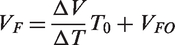
In equation (10), ΔV/ΔT is the slope of the VF–T0 relationship and VFO is the intercept on VF axis. Using the VF–T0 relationship, the junction temperature at any current level can be obtained from equation (11) provided the VF–T0 relationship data exists at the desired current level.
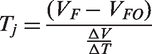
As seen from Figure 4, the slope of the VF–T0 relationship becomes steeper with the increase in drive current. The slope reduces from −7.58 mV/℃ to −14.97 mV/℃ when the current is varied from 5 mA to 270 mA. In order to overcome a number of uncertainties, measurement of VF against Tj needs to be performed at different current levels. Hence, it is important first to perform calibration measurements and then perform actual junction temperature measurements.
As seen from Figure 5 a strong temperature dependence can be clearly seen in the I–VF characteristics of the LED luminaire. When the oven temperature is changed from 10℃ to 90℃, corresponding to a drive current of 270 mA the drop in VF is little more than 1.5 V.
LED luminaire VF and I characteristics for different oven temperatures.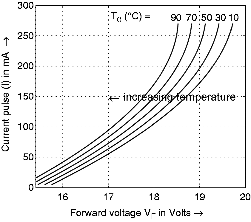
After the measurements in the temperature controlled oven had been done the actual junction temperature measurements were performed on the LED luminaire. The LED luminaire was switched on with the driver and the forward voltage VF and drive current ‘I’ was measured at ambient conditions similar to the actual operating environment of the LED downlight. During this time, the temperature of the heat sink and the driver temperature were also monitored using thermocouples. The variations of LED luminaire drive current ‘I’, forward voltage VF and luminous flux are shown in Figure 6. The LED luminaire was allowed to operate for period of 1 hour until the light output stabilized. After this period, the data were recorded and used for analysis. It was observed that with 24 hour continuous operation of the LED downlight no significant changes in light output or other operational parameters were noted. Hence 1 hour recorded data is sufficient for analysis.
LED luminaire drive current, forward voltage and luminous flux variations with time.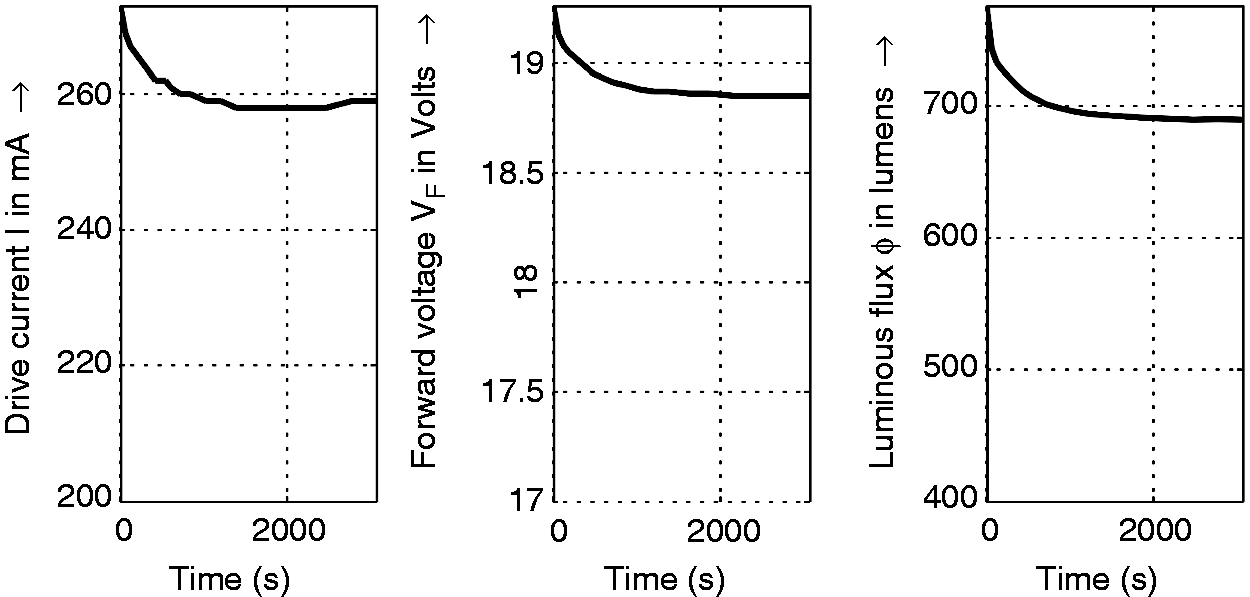
The procedure for obtaining junction temperature values from the recorded forward voltage and drive current is graphically illustrated in Figure 7. Making use of the recorded values of drive current ‘I’, the forward voltage VF during the LED downlight operation, the VF–Tj relationship corresponding to the drive current of interest and equation (11), the junction temperature of the LEDs during operation can be estimated. Just after switching on the LED downlight, VF = 19.26 V and I = 270 mA and the corresponding junction temperature is approximately Tj = 41℃. A straight line corresponding to VF = 19.26 V is drawn such that it intersects the VF–Tj line corresponding to current level of 270 mA (point A). The intersection point is the approximate junction temperature of the LEDs at that point in time. Similarly Tj corresponding to the final steady state can be found out with steady state values of VF = 18.85 V and I = 258 mA (point B). As seen from Figure 7, it is approximately 66℃. The same method is applied to estimate the junction temperature from forward voltage VF and drive current ‘I’ values recorded from the start till the steady state is reached. This estimated junction temperature is plotted with temperatures of the driver and heat sink and is shown in Figure 8a.
Illustration of the method for estimating Tj from the VF–Tj relation. (a) Temperature variation profile of the junction, driver and heat sink. (b) Thermal characterisation parameter from junction to heat sink.
By making use of the thermal performance metric defined in the Joint Electron Device Engineering Council (JEDEC) recommendation
8
we can validate the accuracy of the junction temperature results obtained using the forward voltage method. JEDEC defines a thermal characterization parameter (Ψ). This is used to calculate junction temperatures of semiconductor packages for an application environment. As shown in equation (12) it is used to associate the junction temperature Tj with TX the temperature of a specified region along the heat flow path. Ψ is expressed in terms of ℃/W.
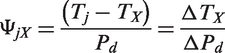
In equation (12), ΨjX represents the thermal characterization parameter from the junction to point ‘X’ along the heat conduction path, it considers only the heat that flows along the path under consideration until point ‘X’. Alternatively, under steady state conditions ΨjX can be expressed as the change in the temperature at point ‘X’ for unit power applied. If ΨjX, TX and Pd are known, then junction temperature Tj can be estimated using equation (12).
The method of estimating thermal characterization parameter Ψ along heat conduction path as defined in JEDEC 8 is taken as a reference; it is not adopted completely or measured as it is defined in the recommendation. This work looks at the possibility of introducing a concept of thermal characterization parameter for LED luminaires with a heat sink under normal operating conditions; this is on similar lines to Ψ as defined in JEDEC. 8 The thermal characterization parameter can be reported by the LED luminaire manufacturers, and can be used to compare the thermal performance of various LED luminaires under identical test conditions.
The proposed work looks into the fact that standardized results obtained by applying the concept of Ψ as defined in JEDEC can help to compare the relative thermal performances of different LED luminaires. An added meaningful assessment is possible if the measurement conditions are understood along with the aspects affecting thermal performance of the LED luminaires. The temperature rise along the heat sink and the heat conduction path is due to the rise in the junction temperature of the LEDs; this condition requires a thermal metric relating the junction and the temperature of a point on the heat sink along the heat conduction path. The thermal characterization parameter Ψ in this work refers to ratio of change in temperature at a point along the heat conduction path on the heat sink to the power to be dissipated as shown in equation (12). This is similar to the concept of thermal resistance.
In this work, Ψ is the thermal metric and is measured under actual operating conditions at a point on the heat sink of the luminaire. As most of the heat flows from the heat sink, a point on the heat sink is chosen for temperature measurements. This point can be any random point on heat sink. It is important that the temperature monitoring at this point should be done continuously till the steady state is reached. This measurement is done along with the photometric and electrical measurements as per national and international standards. The profiles of the operational parameters recorded during the luminaire operation are shown in Figures 6 and 8.
By measuring the temperature rise of the heat sink and power dissipated, the thermal characterization parameter from junction to heat sink (ΨjHS) can be found using equation (12). Under steady state conditions, the thermal characterization parameter ΨjHS was found to be 9.31℃/W and its profile over operating time is shown in Figure 8b. The same thermal characterization parameter ΨjHS was found using junction temperature values measured using VF−Tj method, heat sink temperature and power dissipated. Its value under steady state conditions was found to be around 7.90℃/W. Its profile over operating time is shown in Figure 8b. The difference between values of ΨjHS obtained using two methods is 1.41℃/W. The heat sink temperature rise was measured using a K-type thermocouple with an error of ±1.1℃. Hence the values of ΨjHS calculated using two methods can be accepted.
The junction temperature Tj estimated from ΨjHS measurement under steady state conditions is around 72.10℃. The profile of Tj during operating time estimated from ΨjHS measurement is shown in Figure 8a. The profile of Tj during operating time measured using VF–Tj method is also plotted in Figure 8a. Under steady state condition using VF–Tj method, Tj is around 66.66℃. The difference between values of Tj obtained using the two methods is 5.44℃. This difference is due to uncertainties in thermocouple measurements of the heat sink temperature and the propagation of this error in the calculation of Tj. The junction temperature values obtained using the VF–Tj method and ΨjHS are separated by a constant factor and are close enough to each other, hence junction temperature measurement done using the VF–Tj method can be accepted as representative of the junction temperature of LEDs in the LED downlight. Thus, the VF–Tj method based on forward voltage measurement can be proposed as one of the methods to monitor and measure the junction temperature of LEDs in a LED luminaire.
6. Conclusions
The weakest links in an LED luminaire are the power supply and the thermal management system. The majority of LED luminaire failures are related to thermal issues; the LED’s useful life and performance are directly related to thermal management and the resulting junction temperature of the LED. Higher junction temperatures cause a reduction in light output and speeds up LED aging. Proper thermal management of an LED luminaire and mechanical construction are vital for performance. This work proposes a method based on the strong correlation between the forward voltage drop of a LED junction and the temperature of that junction to measure and monitor the junction temperature of LEDs in a luminaire. This non-invasive method can be used by LED luminaire designers to estimate junction temperature of LEDs in a market-ready luminaire.
Comparing junction temperature measurement of a stand-alone LED light engine with the measurements taken for the same light engine inside a market-ready luminaire is the future scope for this study. Measurements can be made to compare the photometric and thermal performance of a stand-alone LED light engine and a LED luminaire under steady state conditions.
Footnotes
Funding
This research received no specific grant from any funding agency in the public, commercial or not-for-profit sectors.