
Abstract
In this paper, we propose a method combining a deconvolution algorithm and a feedback modification to design a freeform lens for structured light illumination. The deconvolution algorithm can alleviate the blur effect caused by the extended light source and the feedback modification can further improve the quality of the structured light by iteration. A lens for a linear sinusoidal pattern is designed by the proposed method. Simulation results show the contrast is 89%, compared to 57% achieved by the conventional design method.
1. Introduction
Nowadays, structured light illumination systems have been widely used in fluorescence microscopy for higher resolution1,2 and 3D shape measurement for contactless and precise measurements.3,4 Most of the systems generate the structured light by a grating or spatial light modulator,5–7 but these are complicated and expensive. As light-emitting diodes (LEDs) become widely used in common life and industry and freeform optics are widely used in non-imaging optics8–12 and imaging optics13–16 an LED with a freeform optical element has become an alternative way to achieve structured illumination with less cost and difficulty.
Most freeform optics design methods for LEDs are based on an ideal point source. However, the actual extended sources will blur the patterns, and decrease the contrast. In this paper, we consider the actual pattern generated by an extended source as the convolution of the pattern generated by a point source and the point spread function (PSF) of the freeform optical element. Then we introduce the deconvolution algorithm to calculate a new pattern generated by the point source that can eliminate the blur effect. Finally, a feedback modification method is used to improve to quality of the structured light. Using the methods proposed in this paper, a freeform lens is designed. It can generate a linear sinusoidal pattern on the target plane, and the contrast is 88%, demonstrating the suitability of a freeform optical element for designing structured light illumination systems.
2. Design method
2.1. The grids division of the light source
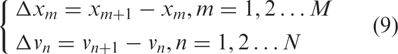
In this paper, our goal is to design a freeform lens to generate a linear sinusoidal illumination pattern on the target plane. The light source is an LED chip with a size of 1 mm × 1 mm. The linear sinusoidal pattern means the illuminance distributes sinusoidally in one direction, but uniformly in the vertical direction. Considering the characteristic of the illumination pattern and matching the rectangular grids on the target plane, the grids of the light source are divided in the The 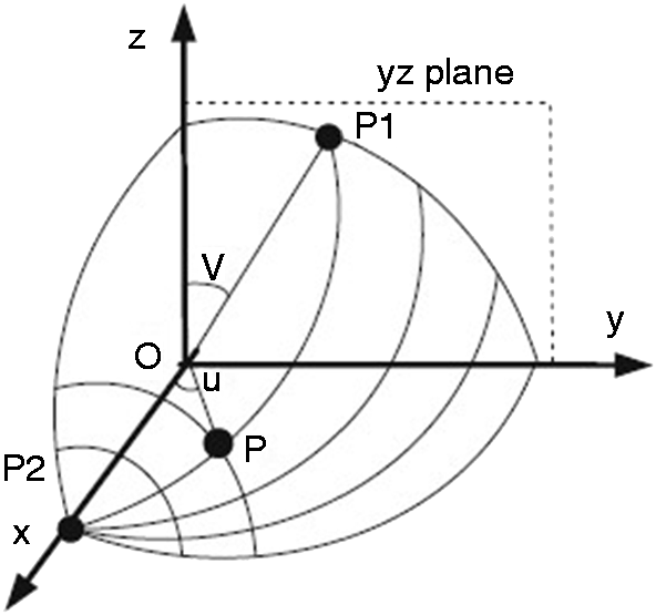
The relationship between
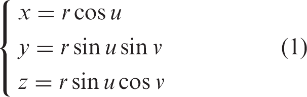

The LED source usually can be approximated as a Lambertian emitter, so the luminous intensity of the light source is:

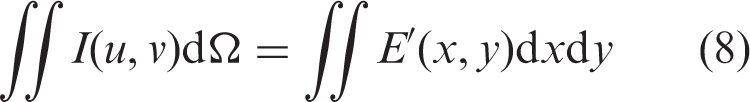
Equation (4) is the formula to calculate the luminous flux in an arbitrary solid angle, which can help establish the mapping relationship between the light source and the target plane later.
2.2. Deconvolution method
While designing a freeform optical element for uniform illumination, the actual LED can be assumed as an ideal point light source if its size is small enough compared to the optical element. However, when designing a structured light illumination system which requires high contrast, the blur effect of the extended source has to be considered. If the extended source is considered as a bunch of point sources during the design, the actual illumination pattern can be described as the convolution of the desired sinusoidal illumination pattern and the PSF of the optical element.3,9,16 So, the ideal sinusoidal pattern will deteriorate and decrease the contrast of the fringes.
The convolution of the designed sinusoidal illumination pattern and the PSF can be described as:

Because in this design, the illuminances distribute sinusoidally only along the y direction, so, we only consider the blur effect on y direction. In equation (5),
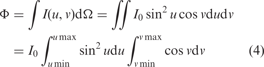
So, in order to eliminate the blur effect, the designed illuminance distribution along y direction should be:
(a) The sinusoidal pattern (b) the rectangular PSF, and (c) the target pattern of the point source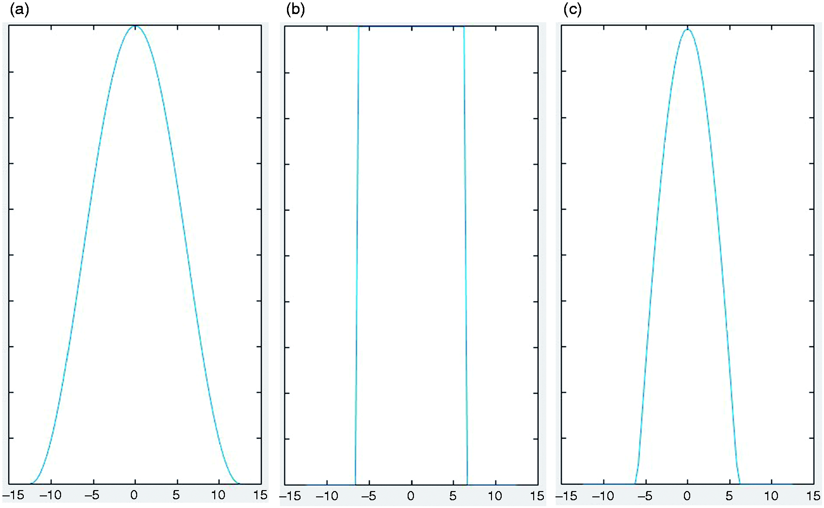

2.3. Calculating the mapping relationship and constructing the freeform lens
After obtaining
The mapping relationship can be calculated by using equation (4) and the numerical integration of the illuminance on the target plane. The mapping relationship is showed in Figure 3. In this design case, x on the target plane only corresponds to u, and y only corresponds to v.
Mapping the relationship between source and target plane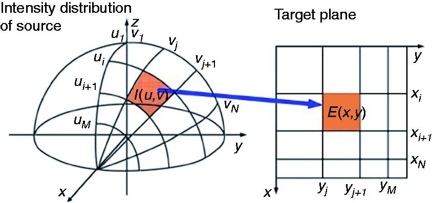
Then, after the mapping relationship between
2.4. Feedback modification
Through the steps from Section 2.1 to 2.3, a freeform lens is designed and constructed. However, because of the calculation error during the surface construction, 11 the error of the deconvolution algorithm and numerical integration, the approximation of the PSF, and the energy loss when the rays passes through the lens surfaces, the simulation result may have a large deviation from the ideal one. So, we introduce a feedback modification method10,12 to adjust the mapping relationship obtained in Section 2.3.
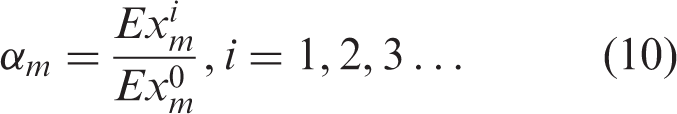
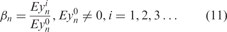
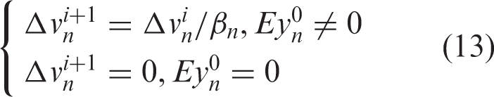
Considering the characteristics of the illuminance pattern and the relationship, the x and v are modified by the simulation data, respectively. Let

3. Design example
The example is to generate a linear sinusoidal pattern on the target plane, whose period is 25 mm, the width of the LED chip is
Using the design method we propose in Section 2, a freeform lens is designed and iteratively modified 15 times. The top view side, side view and the 3D model of the optimized lens are showed in Figure 4, and the basic sizes of the lens are marked.
(a) Top view, (b) side view and (c) a 3D model of the freeform lens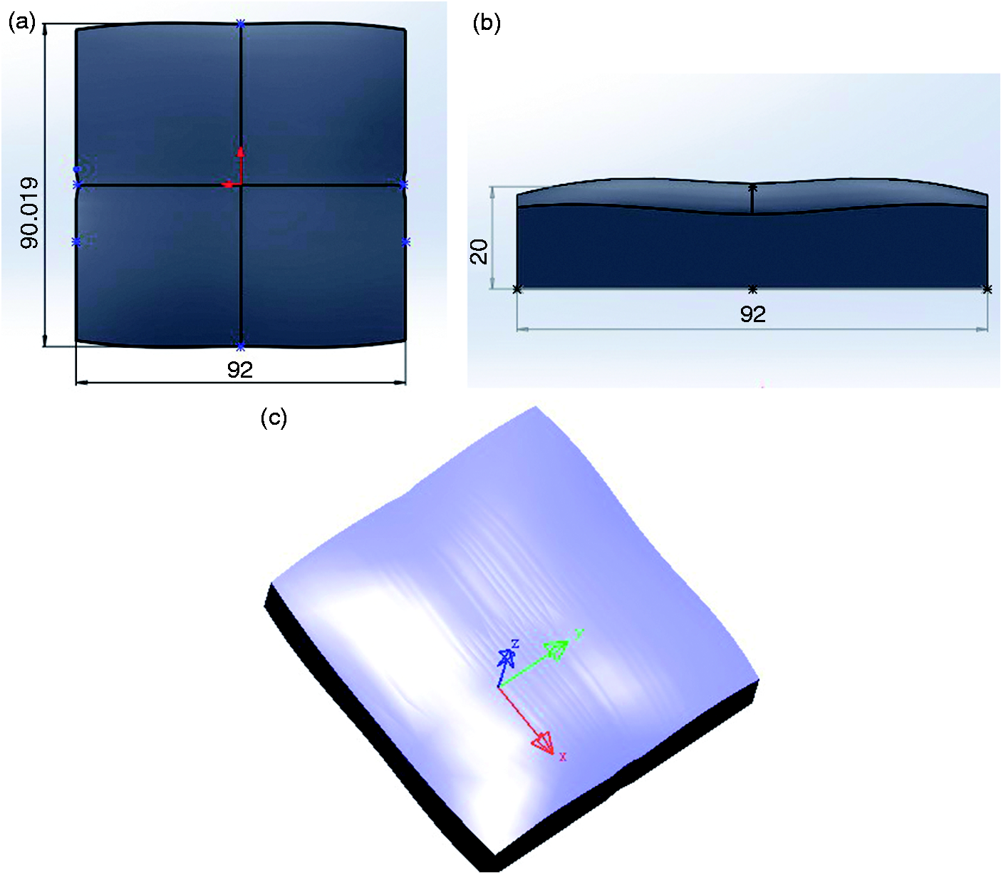
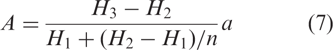
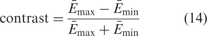
We also designed a lens for structured light illumination without using the deconvolution method and feedback modification for comparison. The simulation result is showed in Figure 5. To evaluate the quality of the structured light, we define the contrast as:
Simulation result of the lens without using the deconvolution method and feedback modification Simulation result of the lens designed using the deconvolution method and feedback modification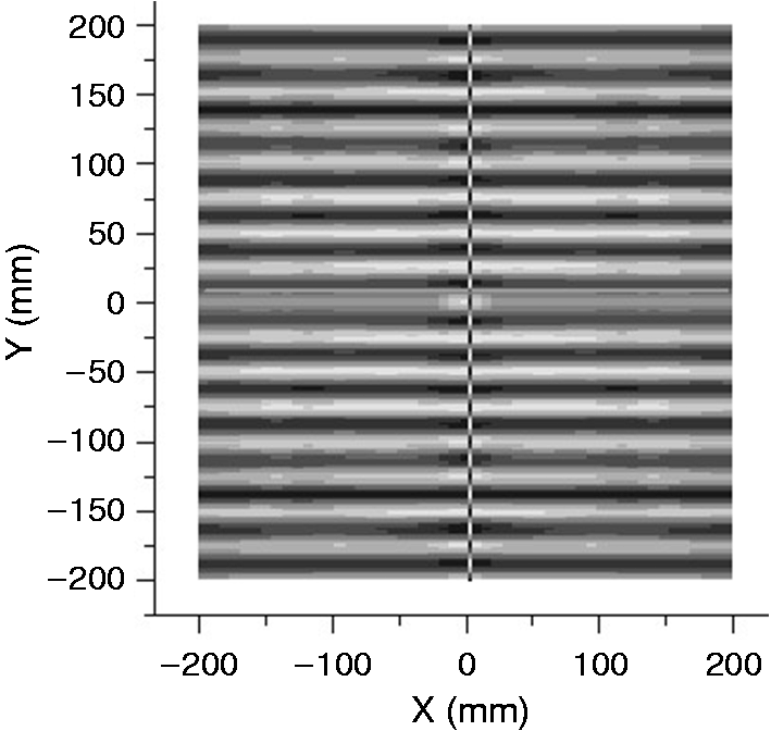
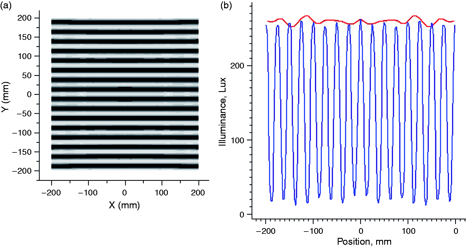
From the simulation data of the final lens,
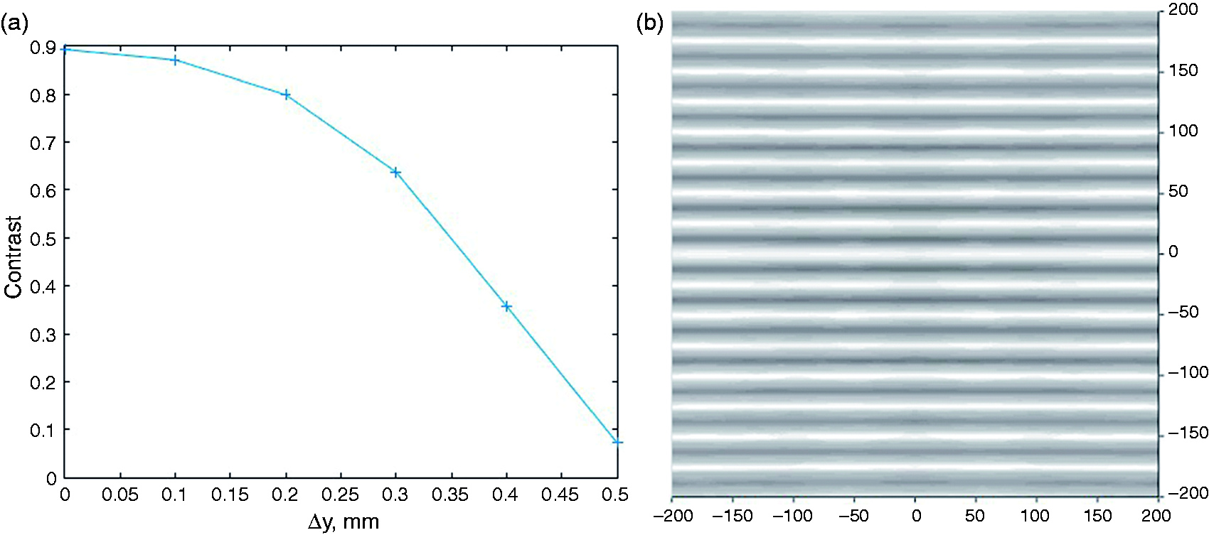
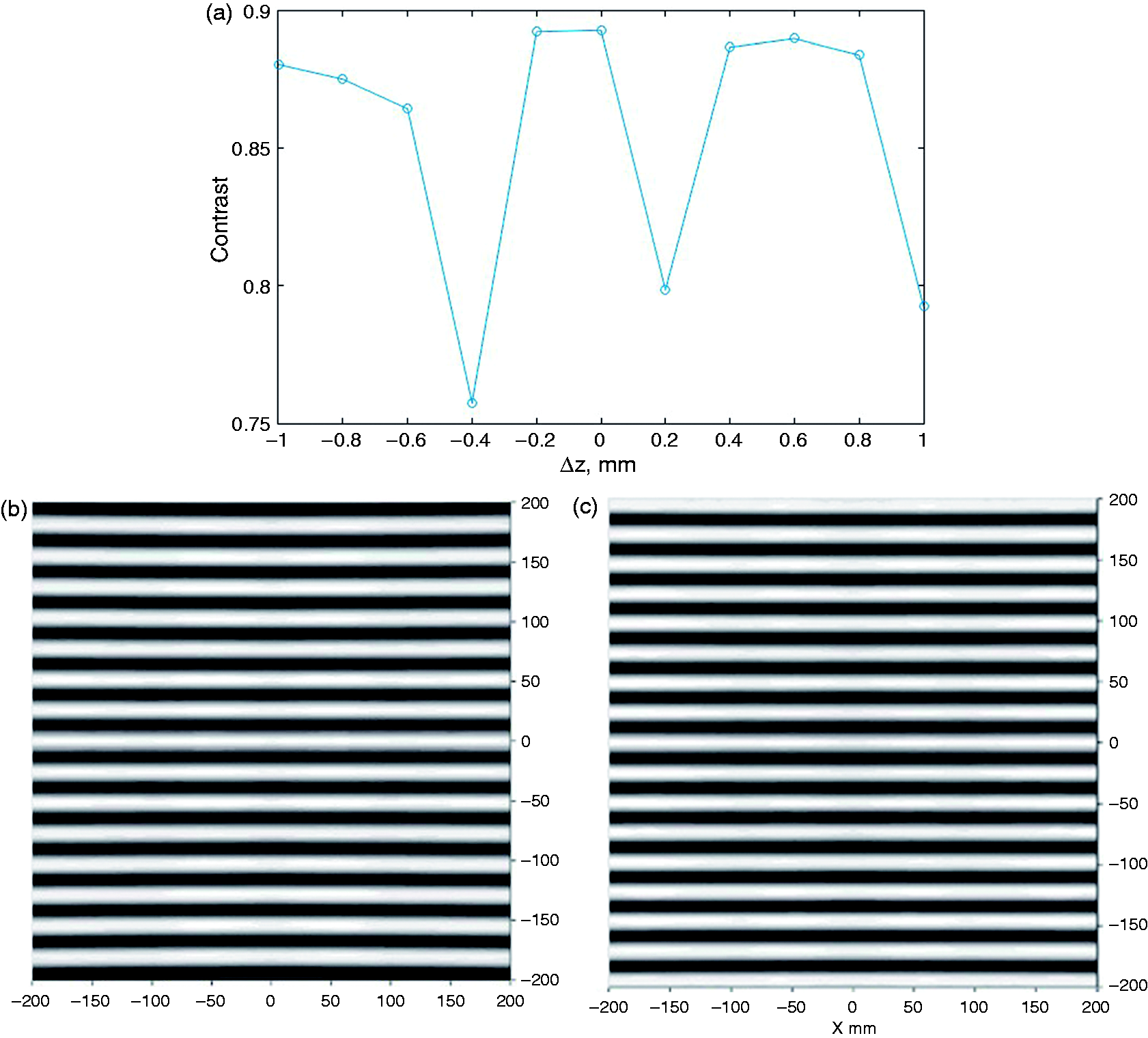
In addition, we should discuss the positional tolerance between the LED and the lens, which will help in the assembly of the system. Firstly, we discuss how the position error along the x axis ( (a) The change of contrast and RMS with (a) The change of contrast with (a) The change of contrast with 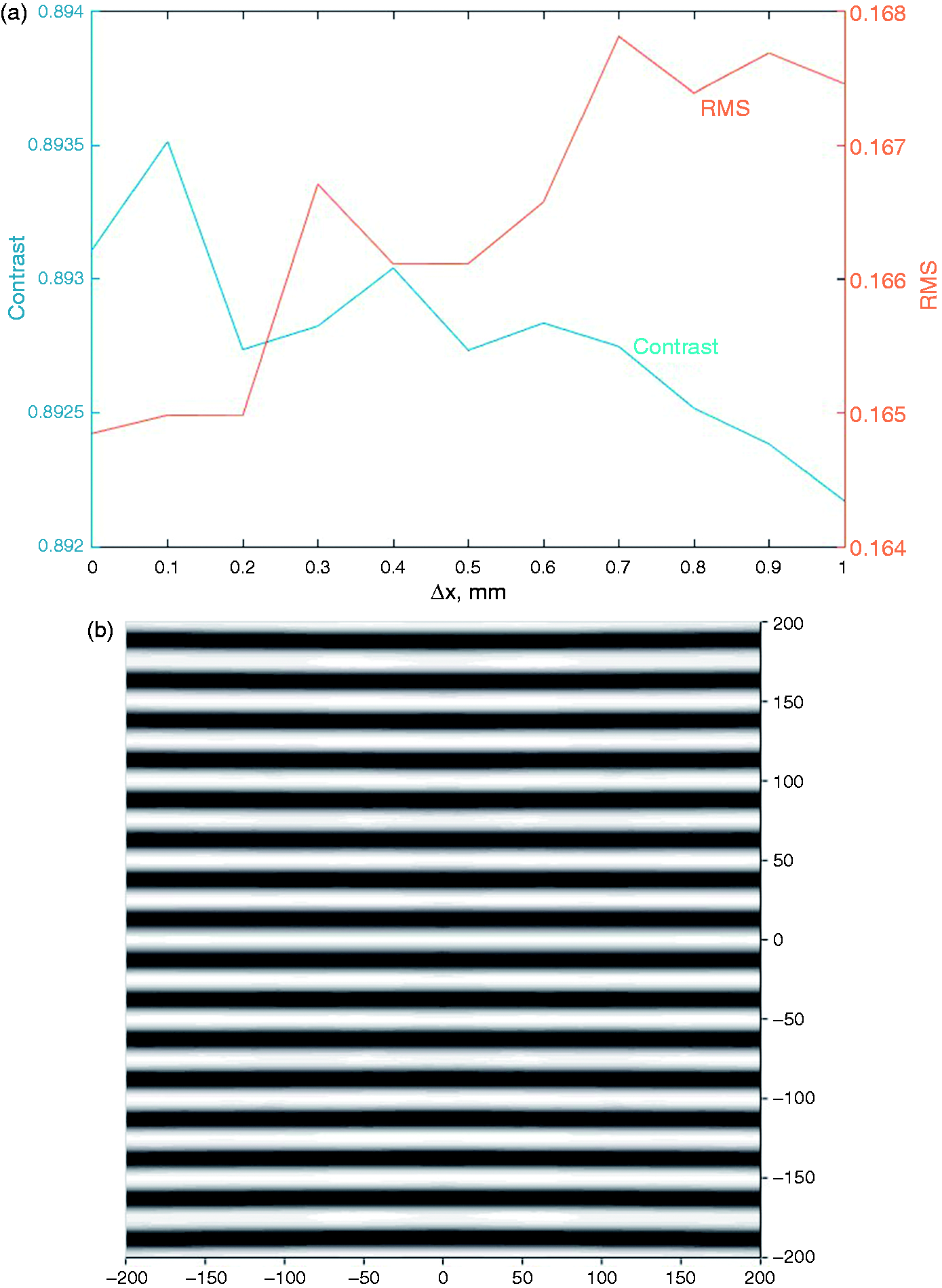
4. Conclusion
In this paper, we develop a method which combines a deconvolution algorithm and feedback modification. This method can achieve an accurate linear sinusoidal structured light illumination, and it can be used to design structured light in other periodic patterns as well, for example, a triangle fringe pattern. To realize that, we should replace the sinusoidal distribution of illumination
Footnotes
Declaration of conflicting interests
The authors declared no potential conflicts of interest with respect to the research, authorship, and/or publication of this article.
Funding
The authors disclosed receipt of the following financial support for the research, authorship, and/or publication of this article: This work was supported by the National Key Research and Development Program of China (2016YFF0101400), Natural Science Foundation of Guangdong Province (2016A030313473, 2015A030310278), the Key Technologies R&D Program of Guangdong Province (2016B090918057), the Key Technologies R&D Program of Guangzhou City (201704020038, 201704020182), and supported by State Key Laboratory of Pulp and Paper Engineering (No. 201537).