
Abstract
Daylighting using natural illumination system (NILS) is gaining popularity due to transition to the renewable and non-conventional energy resources. In the proposed work, optomechanical design, numerical analysis, experimentation and integration of a modular Fresnel lens for NILS to effectively harness the sunlight is discussed. The modular and integrated design delivers uniform light at the receiving area of the daylight transportation system. This modular Fresnel lens is a combination of linear Fresnel lenses designed to offer a moderate concentration ratio to avoid hot spots. The distribution of solar radiation on the focal plane/entry section of the plastic optical fibre bundle (daylight transportation system) is simulated using the ray-trace technique for a lens system with a concentration ratio of 81. The irradiance distributions at the focal plane were found uniform with a radiometric and photometric transmission efficiency of 72.45% and 85.96%, respectively, for the lens element. The overall photometric transmission efficiency of the system with 10 m long plastic/acrylic optical fibre cable was found as 40.97%.
1. Introduction
With the proliferation of the human population, energy demand is escalating at exponential rates. The annual per capita consumption of electricity has increased from 631 kWh (2005–2006) to 1181 kWh (2018–2019) in India. 1 The main source for bolstering energy generation has been fossil fuels. These fuels are sparse and require a long time to regenerate. The coal consumption for power generation in 2004–2005 was 278 million tonnes which increased to 628.90 million tonnes in 2018–2019. 1 As per the Ministry of Power of India report July 2020, about 62.2% of the power need is fulfilled using thermal fuel which consists of coal, lignite, gas and diesel. 2 The major issue with freighting these resources is that they are exhaustible and also a rich source of pollution. The use of renewable energy resources is the best alternative for this problem. Due to the incessant rise in the population, the living spaces are shrinking and multi-story buildings are being constructed in full swing. The gargantuan buildings are restricting the sunlight to reach the working area. The use of windows is not sufficient to lighten the buildings. The continuous use of artificial light is harmful to humans as it is limited to aggravating depression, aggression, eye strain, muscle atrophy, obesity as well as diabetes. 3 These circumstances can be remedied to great extent by daylighting. Daylighting has advantages over artificial lighting, for example, it is good for occupants’ health, provides visual comfort and thermal comfort, eco-friendly in nature, imparts natural colour rendering, good for the wellbeing of the occupant and helps in reduction of carbon footprints. Lighting’s share in the total residential electricity consumption in India is estimated to be in the range of 18%–27%, 4 whereas the electrical lighting cost is approximately 40–50% of the total energy cost. 5 If a suitable daylight system is used, it is estimated that approximately 50–80% of lighting costs may be reduced. 6 Thus, the importance of the daylighting system strengthens.
The daylighting system utilizes the sun, a free source of energy, for lighting purposes in the different working areas. Various conventional daylighting systems like windows or shelves are not able to illuminate the distant spaces and also provide uneven distribution of light. A technically more advanced type of innovative daylighting systems classified as a passive daylighting system (no sun tracking) and an active daylighting system (with sun tracking) are being used for illuminating deep spaces. In the case of passive systems, the mirror light pipe (MLP) is integrated with a daylight collector following basic light redirecting laws and mounted on the top of the entry section of MLP.7–10 In the case of active daylighting devices, the light is propagated in the optical fibre bundle. It has been observed that the passive daylighting systems are easy to construct and they cost less as compared to the active system, but the efficiency of an active system is much higher than the passive systems.11,12 In an active system, the beam component of sunlight is focused on the fibre bundle inlet using a concentrator, for example, Fresnel lens and parabolic mirrors. 11 A very high temperature is attained at the focus plane while concentrating the beam sunlight which leads to various design challenges. Normally, the conventional Fresnel lens is designed using cuts according to an aspheric surface profile in order to minimize the imaging optical aberrations.13,14 The continuous aspheric surface of the lens is collapsed onto a plane. As the refractive power of a lens is contained only at the optical interfaces (i.e. the lens surfaces), the optical material is removed as much as possible while still maintaining the surface curvature. A Fresnel lens is used as a cost-effective, lightweight alternative to conventional continuous surface optics. When the conventional Fresnel lenses are used as a collector for the active daylighting system, then due to their point focus design, the entire sunlight is focused at a point on the fibre inlet section. This damages the entrance of the optical fibre especially when polymethyl methacrylate (PMMA) is used as the fibre material which cannot work under a temperature exceeding 70°C. 15 Only silica optical fibre (SOF) can work with such high temperatures (more than 700°C). 16 Though SOF can work with high temperatures but are expensive, whereas PMMA optical fibres are of low cost. To use PMMA optical fibres as a light transport system, controlled temperature at the interface is the prime challenge.
In the last few decades, some prototypes of tracking-based active daylighting systems were made commercial, for example, Himawari 17 and Parans. 18 Both systems have a similar principle of operation. They use quartz optical fibres as a light transporting medium. This leads to less light transmission loss and also the system overcomes the heating problem. However, the use of quartz optical fibre makes the system very costly which limits it to be utilized widely by common households. This is the reason this innovation has not been broadly spread in the market up until now. Some other prototypes of tracking-based daylighting system use a combination of both silica and PMMA optical fibres as a light transport system. A shorter length of SOF is used before plastic optical fibre (POF). This results in overcoming the heating problem but leads to optimized integration challenges.19,20 A matching gel is required for the purpose to join SOF to POF.21,22 It makes the system complex and increases losses due to material medium interfacings between SOF, index matching gel, and POF. Generally, the point focusing conventional Fresnel lens is used in the daylighting system; therefore, the secondary optics is used to get uniformly concentrated light at the fibre bundle entry. This further makes the daylighting setup complex in design.22–24
In the proposed work, an active daylighting system using a modular Fresnel lens as a sunlight concentrator and POF as a light transport medium has been used to illuminate the deep dark spaces.
2. System description
Generally, the conventional Fresnel lens is concentric (point focused) or linear (line focused). The proposed modular Fresnel lens is a combination of both concentric as well as linear Fresnel lens. It overcomes the limitations of the conventional concentric Fresnel lens (CCFL) which focuses the light over a point resulting in a high-temperature zone at the receiver end. The purposed design of the modular Fresnel lens is area focus instead of point focus. This distributes the concentrated sunlight uniformly over the area on the focal plane which enables the use of POF alone as a light transporting device. The additional advantage of using PMMA fibre is its flexibility which makes it suitable for application in complex-shaped buildings to transport the light on target areas. The purposed system can work with low-cost optical fibre cable (OFC) by providing low-temperature and uniform illumination at the entrance of the OFC. This system comprises a modular Fresnel lens and transporting device as shown in Figure 1. Here, this modular Fresnel lens works as a collector. The collector is used to collect beam or direct sunlight and redirects it to the focal plane, that is, surface at the entrance of OFC instead of a point. The bundle of optical fibres made up of PMMA is used as a transporting device. Different parameters for sustainable design have been analysed. Numerical analysis has been performed to find the working efficiency of the proposed Fresnel lens. Experimental analysis is performed using the fabricated model of the designed lens. Daylight system using the Fresnel lens and optical fibre cable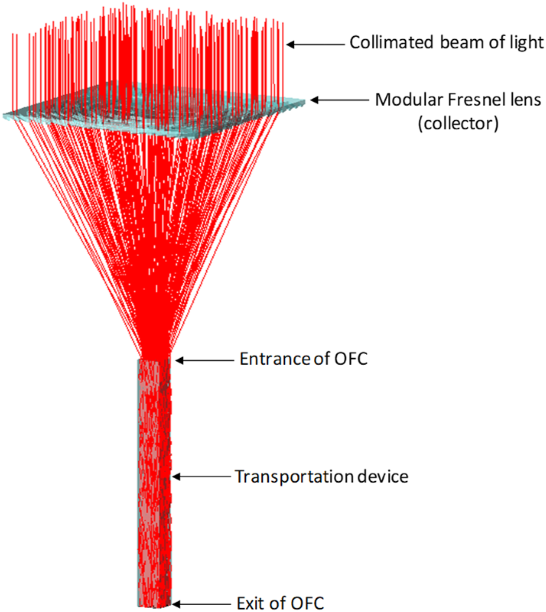
3. Design of the collector lens
The proposed modular Fresnel lens concentrates beam or directs sunlight to uniformly illuminate the entrance of OFC. The lens consists of a set of designed blocks; each of its blocks has the same dimension but the varying configuration of prisms.
25
The target surface area where light has to focus, that is, OFC inlet has the same dimension as the dimension of the individual block. The square-shaped lens design consists of 81 blocks. The light redirected from all the individual blocks focuses uniformly on the OFC inlet. The uniform illumination is obtained by the superposition of flux distributions resulted from modularly faceted individually designed blocks of the Fresnel lens. Figure 2 and Supplemental Figure S1 (see supplementary data) show the nomenclature and model of the modular Fresnel lens, respectively. In Figure 2, Nomenclature of the modular Fresnel lens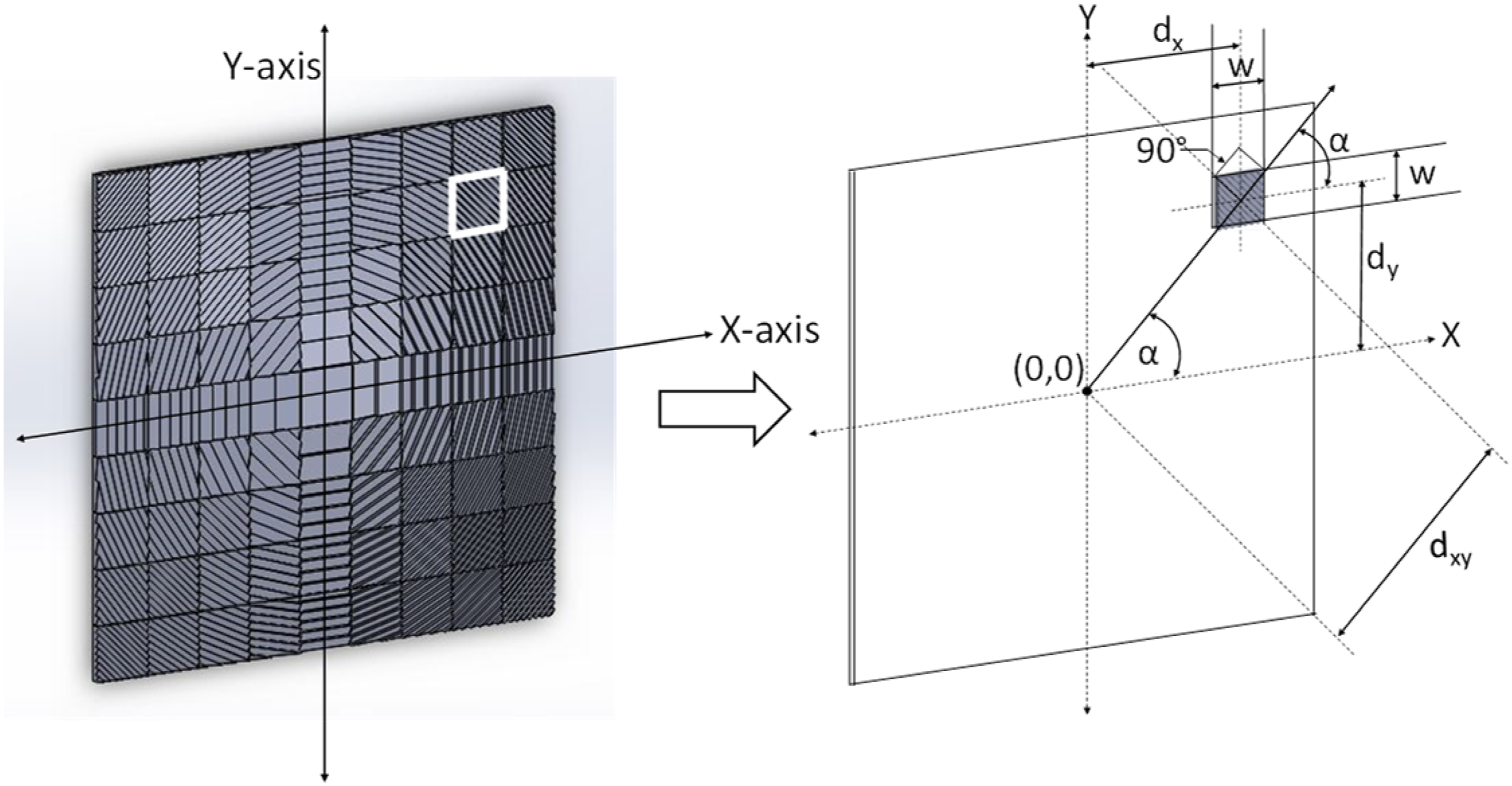
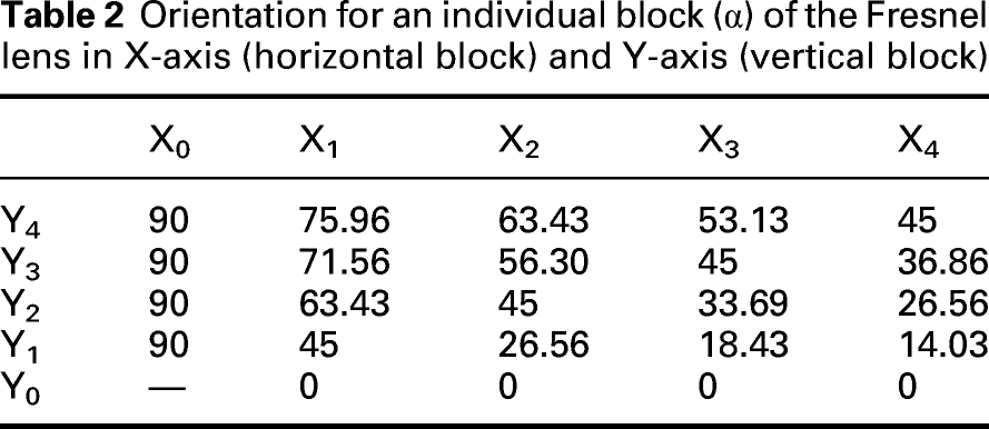
Each one of these 81 blocks was placed at a specific position on the Cartesian x-y plane. The x- and y-axis position of each block is denoted by ith and jth number, respectively. Gt and Tt show groove thickness of the prism and the thickness of the lens, respectively, as shown in Supplemental Figure S1 (see supplementary data). The central block has no grooves as the block directly faces the target area and does not require to redirect or bend incident rays. Rest all 80 blocks contain facet angle (α + 90) of Fresnel lens and facet angle for grooves (ϕ). Alpha (α) is the orientation of each block by taking the x-axis as a reference axis. This angle is different for each block as this angle is formed between the x-axis and the line formed by joining the origin (centre of the lens) and centre of the block as shown in Supplemental Figure S1 (see supplementary data).
Mathematically, angle (α) is defined as shown in equation (1)

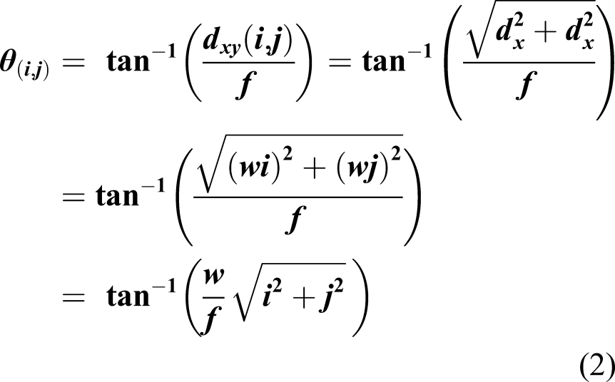
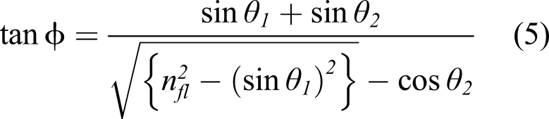
The incidence angle Ѳ for the redirected ray is given as shown in equation (2)
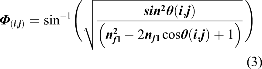
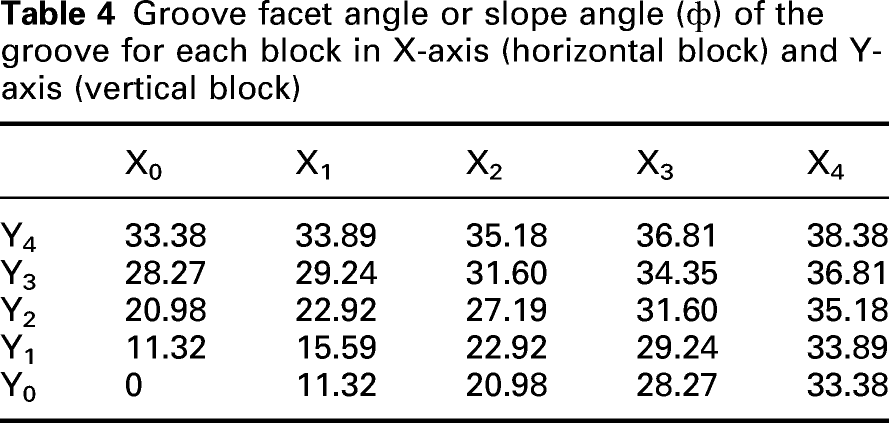
Groove facet angle (ϕ) may also be called a slope angle. The slope angle is the angle formed between the slope face of the prism groove and a plane parallel to the base of the block. The groove’s direction for each block of the Fresnel lens has to extend into a particular direction to refract light rays towards the desired direction.
Facet angle (i, j) derived by Snell’s law is given as shown in equation (3)
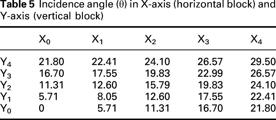
The ray trajectory through the transverse section of the lens and individual block element of the Fresnel lens towards the entrance of the OFC is shown in Supplemental Figure S2(a) (see supplementary data) and Supplemental Figure S2(b) (see supplementary data), respectively. The incidence angle (Ѳ) of a ray to the inlet of the optical fibre increases as the block is far from the centre of the Fresnel lens. Supplemental Figure S3(a) (see supplementary data) shows the ray trajectory through an individually designed block element and Supplemental Figure S3(b) (see supplementary data) shows the perspective view of the designed Fresnel lens converging the light towards the square-shaped target at the focal plane.
4 Numerical and experimental analysis
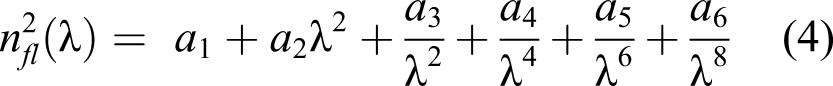
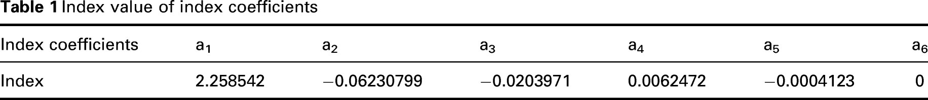
The numerical analysis was carried out to analyse the performance of the CCFL and the designed modular Fresnel lens. The lens model is drawn in three-dimensional (3D) in SolidWorks software. The ray-tracing technique in TracePro is used to estimate the structure and lighting performance of the lens system. The configuration and dimensions of the two lens systems are shown in 6(a) and (b). The radiometric and photometric analysis was done for the equal lens area and the equal focal length of the two lens systems. The effective transmission and the uniformity of the concentration optics were estimated at the focal plane by using solar emulator utility in TracePro. The refractive index (nf1) value of 1.492 was used in the determination of the groove facet angles for both the compared lens system. For radiometric analysis, the wavelength spectrum considered is from 1 nm to 3000 nm. This covers more than 98% of the magnitude of incident radiation from the sun. A total of 300 wavelength samples were considered in between 1 nm and 3000 nm, that is, wavelength sampling, every 10 nm was adopted in the ray tracing. The wavelength band from ∼380 nm to ∼750 nm is responsible for photometric measurements. The refractive index of PMMA, as a function of wavelength, varies as per equation (4) throughout the solar spectrum. Note that the assumption of zero absorption loss is considered for the lens material for the entire wavelength band. Reflection losses (Fresnel losses) have been considered at interfacings
Index value of index coefficients
Orientation for an individual block (α) of the Fresnel lens in X-axis (horizontal block) and Y-axis (vertical block)
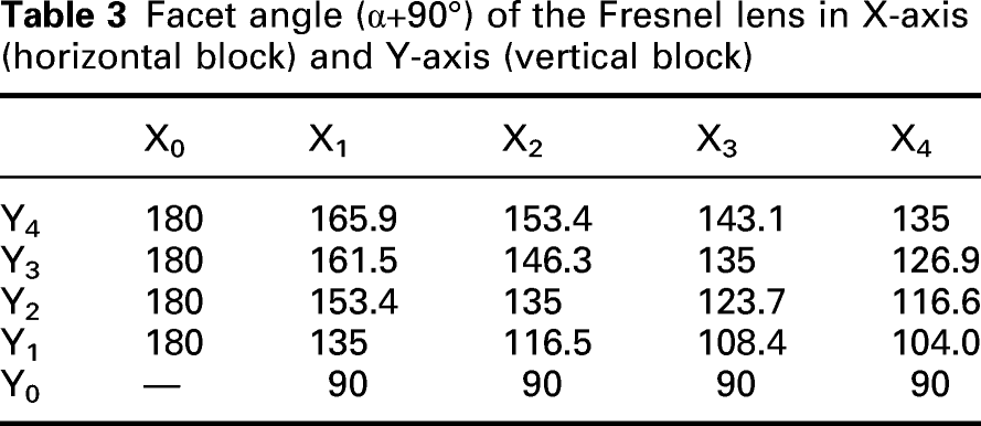
Facet angle (α+90°) of the Fresnel lens in X-axis (horizontal block) and Y-axis (vertical block)
Groove facet angle or slope angle (ф) of the groove for each block in X-axis (horizontal block) and Y-axis (vertical block)
Incidence angle (θ) in X-axis (horizontal block) and Y-axis (vertical block)
The solar emulator utility was used to compare the performance of the CCFL lens and the modular Fresnel lens with the stated parameters. Numerical analysis is considered for direct normal illuminance of 87 090 lux which was observed on 21st June, 12:30 p.m. for the Chandigarh region India (30.71°N and 76.78°E). Also, nearly at this time of the day, maximum altitude is attained by the sun in the entire year span. Therefore, this value of direct normal illuminance on a clear sky day can be regarded as nearly the maximum value of the beam or direct sunlight for the above-mentioned geographical location. This maximum value of beam illuminance can also be regarded as the design value for the proposed lens system. The magnitude of radiometric and photometric results should be equal to or less than the results corresponding to direct normal illuminance of 87 090 lux. Based on the maximum value of direct normal illuminance/irradiance observed in a particular location, an appropriate value of concentration ratio can be assigned to have optimum lens design without hot spot problem. Generally, a large value of the concentration ratio of the lens system is one of the major reasons for the heating problem at the focal plane.
The concentration ratio of the lens (C) is given as per the relation given in equation (6)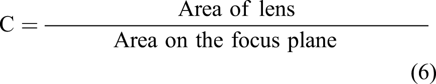
For a modular Fresnel lens of width 90 mm and having a square-shaped target area (entrance surface area of OFC) of width 10 mm, C = 902/102 = 81.
In this study, the concentration ratio for the designed lens is considered as 81. In the case of CCFL, the focused sunlight is also analysed on the circular focus area of 100 mm2 (diameter = 11.28 mm), that is, area similar to the square focus area of the designed lens. Both the lens systems have been analysed and compared for the same area on the focal plane. Though theoretically, the concentration ratio is the same, light distribution/uniformity on the focus area comes out different in both cases. It has been assumed that there is a zero-tracking error while plotting the results of ray tracing.
The performance comparison between CCFL and the designed modular Fresnel lens is depicted in the various subsection of Figure 3 showing the effective transmission and the uniformity of the radiative flux and luminous flux at the focal plane. Figure 3(a) and (b) shows ray tracing in CCFL and the designed modular Fresnel lens. Figure 3(c) and (d) shows the distribution of radiative flux on the focal plane using CCFL and designed Fresnel lens, respectively, while Figure 3(e) and (f) shows the distribution of luminous flux on the focal plane using CCFL and designed Fresnel lens, respectively. Configuration and performance comparison of CCFL and designed Fresnel lens: (a) Concentric Conventional Fresnel lens (CCFL); (b) designed Fresnel lens; (c) radiative flux distribution at fibre bundle inlet using CCFL; (d) radiative flux distribution at fibre bundle inlet using a designed Fresnel lens; (e) luminous flux distribution at fibre bundle inlet using CCFL; and (f) luminous flux distribution at fibre bundle inlet using a designed Fresnel lens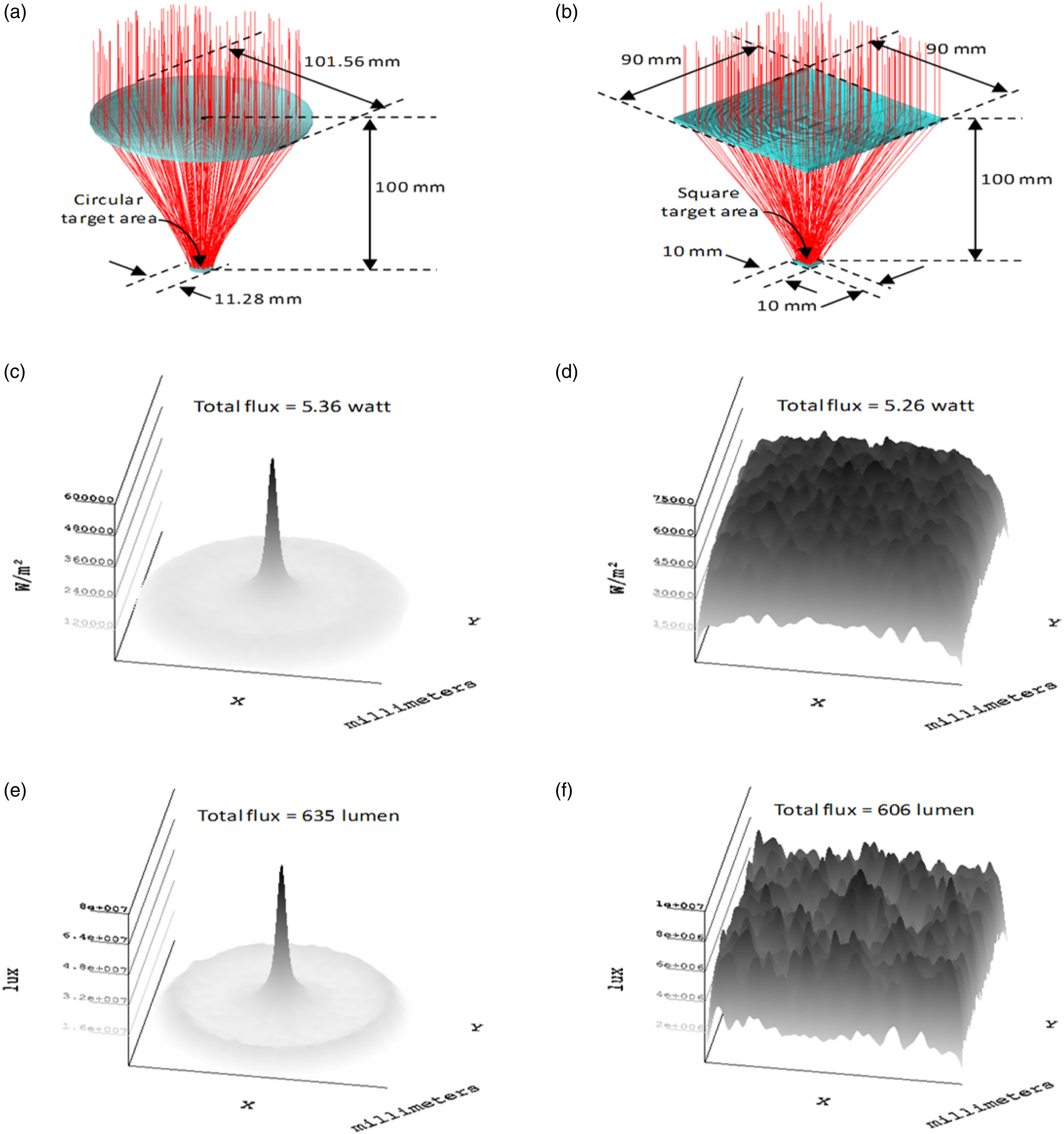
We can see that using CCFL as a light concentrator results in high heat and light value at the centre of the focus plane. The Fresnel point focusing lens (aspheric curvature) is designed for wavelength = 546 nm, that is, corresponding to this wavelength, the lens is going to perfectly converge the incident light at a point on the focal plane. As the refractive index of the lens material is different for different wavelengths, the rest of the light corresponding to other wavelengths travels different trajectories of paths resulting in distributed flux on the target plane. Though the flux is distributed, it is more concentrated on the central region as shown in Figure 3(c) and (e).
Supplemental Figure S4 (see supplementary data) provides conceptual illustration (in side-profile) of collapsing a continuous surface aspheric lens into an equivalent power circular-shaped Fresnel lens with nomenclature conventions. The uniformly distributed heat and light values are observed at the focus plane using a modular Fresnel lens. The radiometric optical efficiency of both the lens system was found more than 70%, while photometric optical efficiency of CCFL and designed modular Fresnel lens came out as 90.07% and 85.96%, respectively. The slight decrease in photometric optical efficiency of the modular Fresnel lens can be attributed to the dispersion of the lens material. The individual sun ray gets dispersed into constituent wavelengths while refracting across the lens prism as shown in Supplemental Figure S5(a) (see supplementary data).
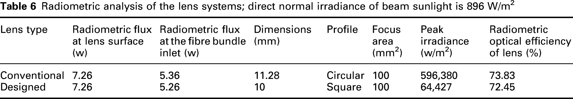
Radiometric analysis of the lens systems; direct normal irradiance of beam sunlight is 896 W/m2
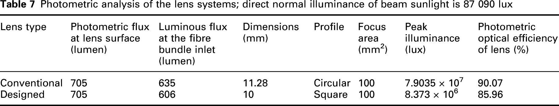
Photometric analysis of the lens systems; direct normal illuminance of beam sunlight is 87 090 lux
Parameters considered for numerical analysis of visible light transmission through optical fibre
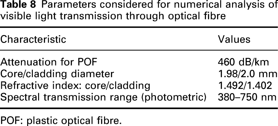
POF: plastic optical fibre.
Light is transferred through the fibre based on the law of total internal reflection (TIR), which occurs due to the difference between the refractive indices of the material medium of cladding and core (ncore > nclad). The numerical aperture (NA) of an optical fibre depends on the refractive indices of the core, cladding, and outer medium of the fibre. If outer medium is air, then NA is defined as shown in equation (7) Maximum incidence angle falling under acceptance angle limit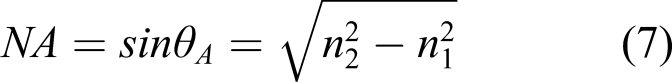

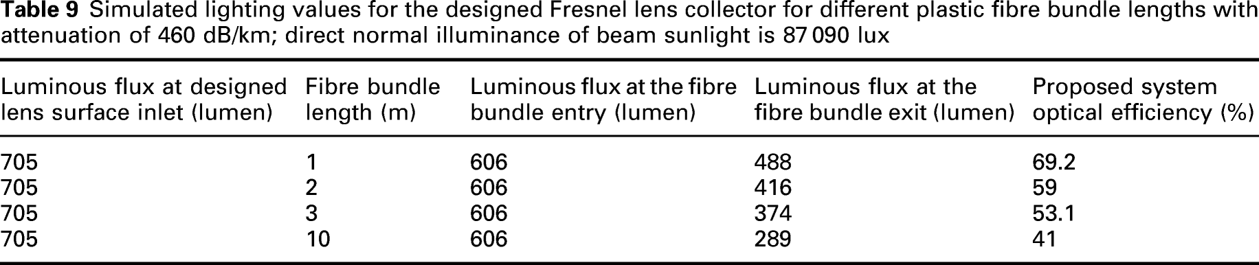
Simulated lighting values for the designed Fresnel lens collector for different plastic fibre bundle lengths with attenuation of 460 dB/km; direct normal illuminance of beam sunlight is 87 090 lux
As the position of the sun regularly changes all the time, a tracking system is required for tracking the sun’s position. The tolerance of the components of setup positioning is needed to consider because errors can exist in the manufacturing process and the alignment technique during installation, etc. The tracking error is considered acceptable up to the condition where illumination value over the receiver drops to 90% of its maximum.26,27 Considering this as the reference, the tilt angles along different axis were noted for light collection efficiency of 90%. The allowable tracking error of ±0.5° about x- and y-axis and ±0.4° about the diagonal axis was found as shown in Supplemental Figure S7 (see supplementary data). The efficiency of the proposed setup corresponding to relative misalignment between lens plane and fibre entry plane was also analysed. It was found that the tilt of 1.4° of the lens element along the X-axis or Y-axis (as shown in Supplemental Figure S8 (see supplementary data)) results in 90% photometric efficiency of the system. Similarly, a tilt of 1.6° along the diagonal axis also led to 90% efficiency of the system. The assumption here is that the surface vector of the fibre entry plane is along the incident sunlight direction. The permissible tilt angle for alignment error is quite large in comparison to the permissible tracking error of the system (i.e. entire setup tilt with respect to incident sunlight).
An array of the proposed design of the modular Fresnel lens may be used to light interiors for required lighting levels. Supplemental Figure S9 (see supplementary data) shows 4 × 4 array of the designed lens acting as a daylight collector. The fibre bundle dimension corresponding to a single lens system is 10 mm × 10 mm as discussed earlier. Therefore, the fibre bundle dimension corresponding to an entire array of the lens system will be 40 mm × 40 mm. The proposed system may be an economically feasible alternative to light pipe systems for lighting requirements at depths up to 10 m, especially when architectural constraints giving large slots in the roof/ceiling system for daylighting is not feasible. The flexibility of POF enables daylight to reach through complicated architectural passages to light target areas without compromising with the lighting levels.
Numerical analysis was carried out to determine the light output through a 10 m long POF bundle integrated with single-lens system setup. Corresponding to direct normal illuminance (DNI) of 87 090 lux, the lighting value received at the exit of 10 m long fibre bundle was 288.84 lumen (i.e. 40.97% efficiency of the system) as shown in Supplemental Figure S10 (see supplementary data).
The candela (angular) distribution of the light emitting from the fibre bundle (of 4 × 4 lens array) at 10 m depth (at 12:30 p.m., DNI = 87 090 lux) is shown in Figure 5(a). Most of the light is between +/−23.7 degree cone as shown in the rectangular candela curve in Figure 5(b). The illuminance values at various depths corresponding to the candela curve are shown in Supplemental Figure S11 (see supplementary data). The relative position of the fibre bundle exit and target area can be adjusted for required lighting levels. If we further want to adjust the beam pattern in order to have the required area to be lit with uniformity, a diffuser of appropriate configuration needs to be installed at the exit of the fibre bundle. However, this comes at the cost of slightly reduced efficiency due to losses at diffuser interfacings. The illuminance graph is for the light received at the exit of 4 × 4 lens array system (16 × 289 lumen = 4624 lumen) [for DNI = 87 090 lux]. (a) Polar candela curve for the light rays exiting the 10 m long fibre bundle (4 × 4 lens array system) and (b) rectangular candela curve for the light rays exiting the 10 m long fibre bundle with FWHM (full-width half maxima) of +/− 26.3°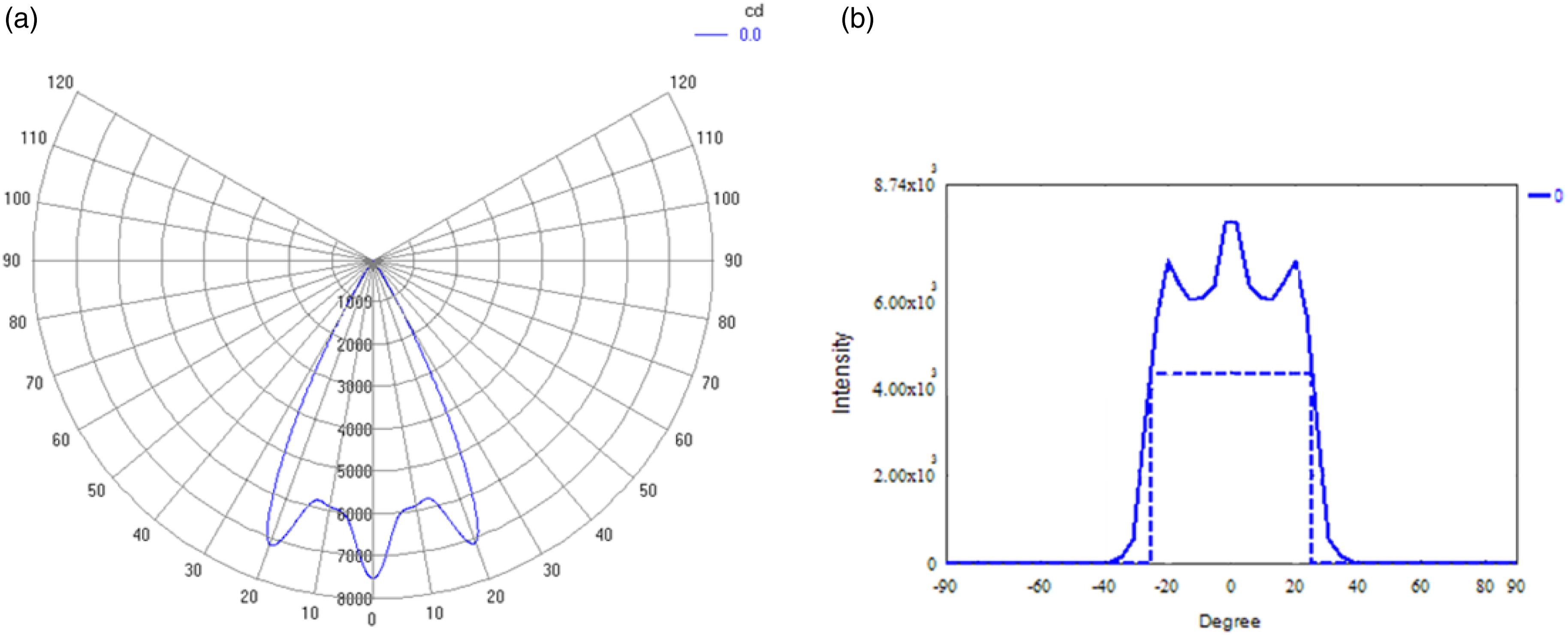
5 Experimentation and integration
Based upon the numerical analysis, the optimized design of the Fresnel lens with 2 mm groove thickness (Gt) and 4 mm total thickness (Tt) was fabricated. Its experimentation was done by using POF as a light transport system. The entrance of the OFC was placed at the focal length of the Fresnel lens. Figure 6 shows the outdoor experimentation of the designed Fresnel lens. Figure 6(a) shows the sunlight getting focused on the black matt surface (perfect absorber) depicting the square-shaped pattern of the focused light on the focus plane. When outdoor experimentation was performed, the ambient temperature was recorded as 40°C. The temperature measured at the focal spot over the black matt surface was ∼85°C using Fluke 17B+ digital multimeter. Figure 6(b) shows the designed Fresnel lens integrated with POF. The temperature measured at the focal spot over the optical fibre entry surface was ∼60°C. Uniform lighting values, at the entrance of the optical fibre, was observed by taking the number of observations at randomly chosen points over the entrance area of OFC. The illuminance values of 1.6 million lux to 1.8 million lux were observed. However, the absolute values of the illuminance may greatly vary from the observed readings since the readings observed were highly sensitive to the position of the light sensor. Any small deviation between the sensor plane and lens plane greatly influences the observed value. A P-9710 optometer from Gigahertz Optik was used for the illuminance readings. Outdoor experiment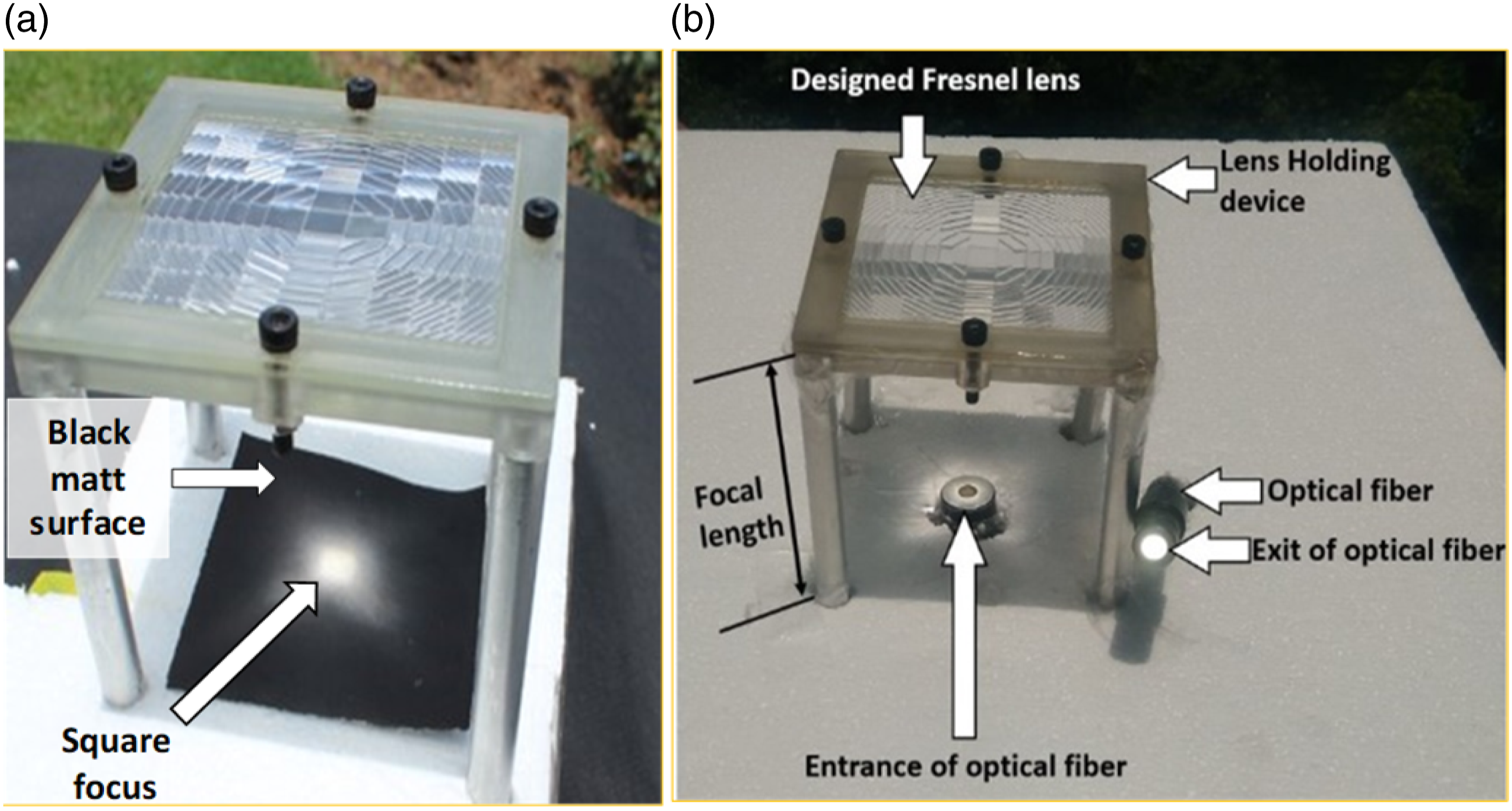
As the illumination provided by the daylight system in the chamber was difficult to sight during the daytime, an artificial light source was used in the lab to show illuminance effects by daylighting device. For indoor experimentation, an artificial collimated light source was used to illuminate the Fresnel lens as shown in Supplemental Figure S12 (see supplementary data). The light is focused at the entrance of the OFC using a designed modular Fresnel lens. When the exit of OFC is inserted in the chamber ceiling, the illuminated chamber can be seen in Supplemental Figure S12(c) (see supplementary data).
6 Daylight collection capability and cost comparison
The high cost of glass fibre [US$140 per metre] 28 in daylighting applications is a well-known fact. In fact, the cost of a glass fibre bundle is quite high as compared to the overall cost of the assembled daylighting device. A 4 × 4 array of the designed lens is considered for appropriate comparison with a few commercialized fibre-based daylighting systems. The fibre bundle dimension corresponding to a single-lens system is 10 mm × 10 mm. This square-shaped fibre bundle consists of 33 POF as shown in Supplemental Figure S6 (see supplementary data).
Cost of one bundle (2 mm dia., 350m long) of POF is 40 US dollar. 29 For the 4 × 4 array of the designed lens with a 10 m long POF bundle, a total of ∼16 bundle will be required. A few references have been taken into consideration in order to compare the cost of the proposed device and lighting performance. 30
Estimated cost of the proposed system (16 lens system)
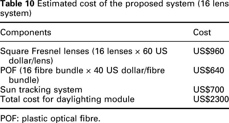
POF: plastic optical fibre.
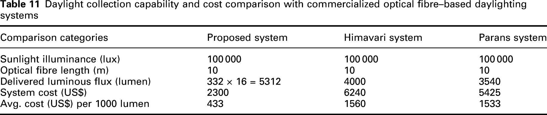
Therefore, luminous flux at fibre exit corresponding to DNI of 100 000 lux will be = (288.84 × 100 000)/87 090 = 331.65, that is, ∼332 lumen.
Daylight collection capability and cost comparison with commercialized optical fibre–based daylighting systems
7 Results and discussions
The design greatly helped in overcoming the hot spot problem due to the lens’s focal spot size of 10 mm × 10 mm. The conventional Fresnel lens is point focus, which makes hot spots by providing very high temperatures at a focused point. Therefore, they are not suitable to work with POF alone. PMMA can only work up to 70°C. A temperature higher than 70°C can burn/melt/diffuse the entrance of PMMA fibre. In the experimental setup, the temperature measured at the focal spot over the optical fibre entry surface was ∼60°C. This confirms the feasibility of the proposed lens system to be integrated with POF corresponding to a concentration ratio of 81.
In the numerical analysis results, CCFL as a light concentrator results in high heat and light values at the centre of the focus plane, while uniformly distributed heat and light values are observed at the focus plane using a modular Fresnel lens. The radiometric optical efficiency was found similar in both the lens systems. The peak irradiance (watt/m2) achieved on the focus plane of CCFL is more than 9 times the peak irradiance achieved using a modular Fresnel lens. Therefore, a significant reduction in the hot spot can be realized from numerical values. Similarly, the peak illuminance (lux) achieved on the focus plane of CCFL is more than 9 times the peak illuminance achieved using a modular Fresnel lens. Therefore, a more uniform distribution of light magnitude into the fibre bundle is achieved which is placed on the focus plane of the modular Fresnel lens. This means that each fibre in the bundle is going to transmit a fairly similar magnitude of luminous flux which is desirable. However, the photometric optical efficiency of CCFL and designed modular Fresnel lens came out as 90.07% and 85.96%, respectively. As the designed lens can concentrate the sunlight uniformly on the entry section of the fibre bundle, therefore, a slightly less photometric optical efficiency of the designed modular Fresnel lens is acceptable. Also, the system does not require any secondary optics/system to get homogeneous irradiance; thus, efficiency received by the system is an acceptable value.
The use of POF alone as the light transporting media was found feasible without a hot spot problem. No use of silica optical fibre (SOP) makes the system less complex and inexpensive though daylight is achieved to moderate depths. An array of the proposed design of the modular Fresnel lens may be used to light interiors for required lighting levels. However, the fibre bundle will be relatively thick (still flexible) compared to the glass fibre bundle used in commercial systems. The proposed system is a possible substitute to light pipe systems, especially when architectural constraints giving large-diameter slots in the roof system is not feasible. The proposed system can serve as an economically feasible alternative to the tubular daylighting device for complex architectural houses where installing the mirror light pipe is a challenging task.
8 Conclusion
This study was basically for the designing of a hybrid lens, having properties of both the linear as well as concentric Fresnel lens for the purpose to uniformly distribute heat and light at the focus area using designed modular blocks. Based on the present study, it was found that a modular Fresnel lens could be an efficient daylight collector in daylighting devices.
The radiometric optical efficiencies of CCFL and designed modular Fresnel lenses were 73.83% and 72.45%, respectively. The photometric optical efficiency of CCFL and designed modular Fresnel lenses were 90.07% and 85.96%, respectively.
The configuration of the proposed solar concentration optics resulted in achieving a uniform flux on the focal plane by the superposition of flux distributions resulted from modularly faceted Fresnel lenses/blocks. The proposed lens design significantly overcomes the problem of the hot spot at the focal plane.
As the heating problem is overcome by the proposed design, we can use only POF as the light-transmitting media for a daylighting system corresponding to a suitable concentration ratio of the lens system. Also, this technique helps to reduce the daylighting system cost by using POFs to transfer the sunlight.
This system can effectively work with ±0.5⁰ tracking error about x- and y-axis while ±0.4⁰ about the diagonal axis. Similarly, the alignment error of ±1.4⁰ about x- and y-axis and ±1.6⁰ about the diagonal axis led to 90% efficiency of the system.
This designed Fresnel lens overcomes existing challenges like hot spot problem and non-uniformity at the entry surface of OFC. During a bright sunny day, the temperature measured at the focus of the Fresnel lens was 60°C, when the ambient temperature was 40°C. Since POF can work up to 70°C without getting damage, therefore, the system can work with POF alone, so no need to use costly SOF which makes the system costly.
The outcome of the study shows significant value addition to the conventional tracking-based daylighting devices. The system is less complex (no extra interfacings at fibre entry) and still gives comparable lighting values with reduced cost.
9 Future work
The lighting performance of the proposed system under the various magnitude of beam sunlight gives satisfactory lighting levels needed for visual tasks, 31 though the illuminance values can be further improved using a concentrator of relatively larger focal length. Since the transmission efficiency is better for light rays with low incidence angle,32,14 the larger focal length of the concentrator results in smaller optical path length travelled by light rays which decreases losses incurred due to attenuation in the fibre. In the proposed system, the maximum incidence angle/refraction angle is very close to the acceptance angle. This leads to more attenuation losses by the light while travelling through the fibre length. But simultaneously, the lesser the F-number, the more will be the dispersion of the light refracted through the prisms. This dispersion factor along with the proposed modular design can be attributed to lessen the heat component (IR) onto the fibre bundle. Therefore, the system feasibility and performance of the proposed model for the various focal length of the concentrator need to be studied.
For large lighting requirements, instead of giving an array of lens systems, the individual lens system may be scaled up. The individual block size and focus spot size (square) will be increased. Since the fibre bundle size is equal to the focus size, a relatively thick fibre bundle will do the needful lighting. The feasibility of the system can be checked, especially the temperature attained at the focal plane is a point of concern.
The colour temperature of the visible sunlight transported interior is an important study for the proposed daylighting system.
Supplemental Material
sj-pdf-1-lrt-10.1177_14771535211063624 – Supplemental Material for Analysis, evaluation and integration of modular natural illumination system using a rectangular Fresnel lens for high performance
Supplemental Material, sj-pdf-1-lrt-10.1177_14771535211063624 for Analysis, evaluation and integration of modular natural illumination system using a rectangular Fresnel lens for high performance by H Garg, DS Bisht, K Sharma, V Kumar, K Kaur and N Garg in Lighting Research & Technology
Footnotes
Acknowledgements
The authors are thankful to the Director of CSIR–CSIO, Chandigarh, for providing the necessary facilities for carrying out this work.
Declaration of conflicting interests
The authors declared no potential conflicts of interest with respect to the research, authorship, and/or publication of this article.
Funding
The authors received no financial support for the research, authorship, and/or publication of this article.
Supplemental material
Supplemental material for this article is available online.
References
Supplementary Material
Please find the following supplemental material available below.
For Open Access articles published under a Creative Commons License, all supplemental material carries the same license as the article it is associated with.
For non-Open Access articles published, all supplemental material carries a non-exclusive license, and permission requests for re-use of supplemental material or any part of supplemental material shall be sent directly to the copyright owner as specified in the copyright notice associated with the article.