
Abstract
In recent times, polymer composites have played an epochal role in transforming material science. Some of their properties such as toughness, strength, flexibility and rigidity have helped them supplant conventional materials such as iron, steel, and aluminium on several occasions. Apart from this, they are light in weight and more cost-efficient, which make them a viable alternative. They have found their application in several fields such as automobile industry, aerospace industry, construction and pipeline industry. Owing to its excellent impact strength, tensile and hardness, natural fibres serve as an excellent replacement. Natural fibres are an environmental friendly, biodegradable and are readily available. The present investigation uses a new fibre for manufacturing the eco-friendly composite material. Mechanical properties such as tensile strength, shear stress, flexural rigidity, impact strength and hardness of a coconut fibre-reinforced polymer composite material are evaluated as per respective ASTM standards. A surface analysis of the material using a scanning electron microscope is also performed. The results are categorized and tabulated accordingly. The values obtained appear to fall in line with the experimental data and hence can be espoused as an alternative material especially in the automotive sector.
Keywords
Introduction
The ever-burgeoning need for humanity to make tougher, lighter and cost-effective material leads to the development of composite materials. Ever since its creation, composite materials have found themselves to be ubiquitous. This research activity deals with natural fibres being used as viable alternatives for traditionally used materials. Samuel et al. 1 evaluated the possibilities of natural fibres such as banana, sisal and coconut fibres in engineering applications. Various tests such as tensile, bending, compressive test and impact test were performed and the strength of the material was evaluated. Abdullah et al. 2 inferred that fibres produced from natural resource give better results than fillers of other sources. Ashik and Sharma 3 studied the properties of jute, hemp and bamboo, which are potential replacement for glass fibres. These fillers have also been properly studied and chosen in the field of constructions and other mechanical applications. Nwankwo and Job 4 identified sisal fibres are in huge numbers in tropical countries like Nigeria. They investigated properties of sisal fibres by blending them with fly ash and used them for constructional purposes like concrete bricks. Aktar et al. 5 made an analysis on the effect of spathe fibre on a high-density polyethylene (HDPE) composite. They found that the thermal conductivity of the composite is increased by 20% and electrical resistivity is gradually increased proportional to spathe-fibre reinforced. The conclusion of their research is coconut spathe-fibre HDPE behaved like an insulator. Sapuan et al. 6 performed tensile and flexural tests with spathe-fibre-reinforced epoxy resin and concluded that it shows inferior results to other natural fibres like banana fibres. Hence, proving that fibre treatment might be necessary depending upon the application that is used in.
The need for natural fibres is increasing exponentially day by day. Vijayakumar et al. 7 made a composite material using coconut spathe fibre and conducted an extensive research on mechanical properties of coconut spathe–kenauf epoxy composites. Lavoratti et al. 8 performed experiments on unsaturated polyester hardwood and studied the dynamic mechanical properties and thermal properties of the composite. It is observed that when the dynamic properties of eucalyptus are increased, the thermal stability also improved.
Al-Maadeed and Labidi 9 classified different types of natural fibres and their effect on recycled polymers. The improvement of physical, environmental and mechanical changes was also discussed. Al-Oqla and Sapuan 10 discussed the possibility of using date palm fibres in fibre-reinforced polymer composite fender for the automotive industry. The study presented a comparative data of the various natural fibres used in the automotive industry. Wȩcławski et al. 11 studied the compressive behaviour in the elastic region and post-collapse behaviour of natural fibre composite. Fiore et al. 12 studied the use of Arundo Donax fibres and reported chemical composition and microstructure of the composite. Ramesh et al. 13 studied the banana fibre-reinforced polymer composite and conducted the surface analysis of the composite through the scanning electron microscope (SEM). Srinivasan et al. 14 also studied glass fibre reinforcement and evaluated the mechanical properties of the composite. It has been observed that hybrid composites tend to have better strength than single fibre composites.
Pantamanatsopa et al. 15 studied the effects of a modified jute fibre on the mechanical properties of green rubber composites. The comparison between natural rubber/untreated jute and natural rubber/treated jute was made. It is identified that natural rubber/untreated jute improves the properties of the composite. Gan et al. 16 reported that the interaction between compressive through-thickness stress and out-of-plane shear stress can enhance the shear stress of the composite at which delamination is initiated. The experimental, analytical and numerical results were presented in their research. Akil and Zamri 17 performed mechanical tests on natural fibre-reinforced composite using dynamic mechanical analysis. They reported the effect of loading and strain rate based on fibre loading and water absorption properties of the composite. Ho et al. 18 identified the critical factors involved in the manufacturing of natural fibre composites and reported various mechanical and thermal properties of natural fibre composites. Bansala et al. 19 studied the composition of bamboo, jute and coir fibre individually, all with epoxy resin. They found the major differences in the mechanical properties from the results of impact test, Fourier-transform infrared and hardness tests and reported that bamboo being more efficient than other fillers. The interfacial matrix adhesion between the matrix and the fibre plays an important role according to Ku et al. 20 They reported that the tensile strength improves with more content of fibre in the composite up to an optimum level after which the strength starts to decrease. Fogorasi and Barbu 21 carried out a detailed study on the chemical composition, microstructure and mechanical properties of cellulosic lignocellulosic fibres. It was aimed to provide a view of greener surface treatments without using dangerous materials. Kane et al. 22 carried out a research on the effect of a coconut fibre trunk on the mechanical properties using fly ash. It was concluded that the coconut fibre contributed to the improvement of the mechanical and microstructure properties of geopolymer composites. Craciun et al. 23 performed a tribological study to determine the characteristics of the friction product by using coconut natural fibre-reinforced aluminium composite. This material was put to test on a brake pad and further tested for tribological behaviour.
To determine Young’s modulus of a composite in accordance with different mixtures, Halpintsai equation is being used as follows:

where
In the present investigations, fibres produced from coconut spathe are used for synthesizing reinforced polyester polymer composite. The spathe fibres are different from the coir fibres and are complementarily stronger than the latter. The resultant composite of different weight fraction of the filler is prepared through compression moulding method. The mechanical properties such as tensile, shear, flexural and impact properties are studied. The interlaminar strength of the composite material is studied. The interfacial arrangement of the fracture is also studied using SEM and the results are presented in detail.
Materials and methods
Nowadays, plant fibres are finding improved and increased applications in many fields, such as automobiles, sports, goods manufacturing and laser equipment. The adverse effect on the environment by the usage of synthetic fibres can be replaced by natural fibres. Hence, the coconut flower cover, which is used for the construction of huts in rural villages of India, was used as a natural fibre in the current investigations. The use of such renewable source as a filler is considered to be a new attempt towards the preparation of composites for industrial applications. General-purpose polyester resin that has good temperature properties, good tensile elongation and extremely high resistivity was used as a base matrix. It is widely used in marine applications, fire retardants and so on. The compression moulding process was adopted for the fabrication of the composite. Firstly, the fibres were extracted from coconut flower covers which readily available. These fibres are known for their high-specific strength and stiffness, low density and low cost, abundant availability and renewable nature. They are also an environmental friendly alternative when compared to glass fibre-reinforced composites.
Processing of composite and characterisation
The composite material was prepared using the hot compression moulding process. The fibres were firstly chopped into smaller pieces and spread uniformly over the surface of the mould. The fibres were distributed in a random orientation. The measured quantity of polyester resin was then applied over the chopped fibres. Three variations of polyster/fibre samples were done having compositions: (i) 20% fibre and 80% polyester resin, (ii) 30% fibre and 70% resin and (iii) 40% fibre and 60% resin. Concomitantly, a compression force of about 200–300 N was applied over the fibres to obtain the desired sample. The environmental friendly composite of dimensions 250 × 250 × 3 mm3 was obtained after allowed them to cool in room temperature. Figure 1 shows the coconut flower cover fibre and composite sample prepared from compression moulding.
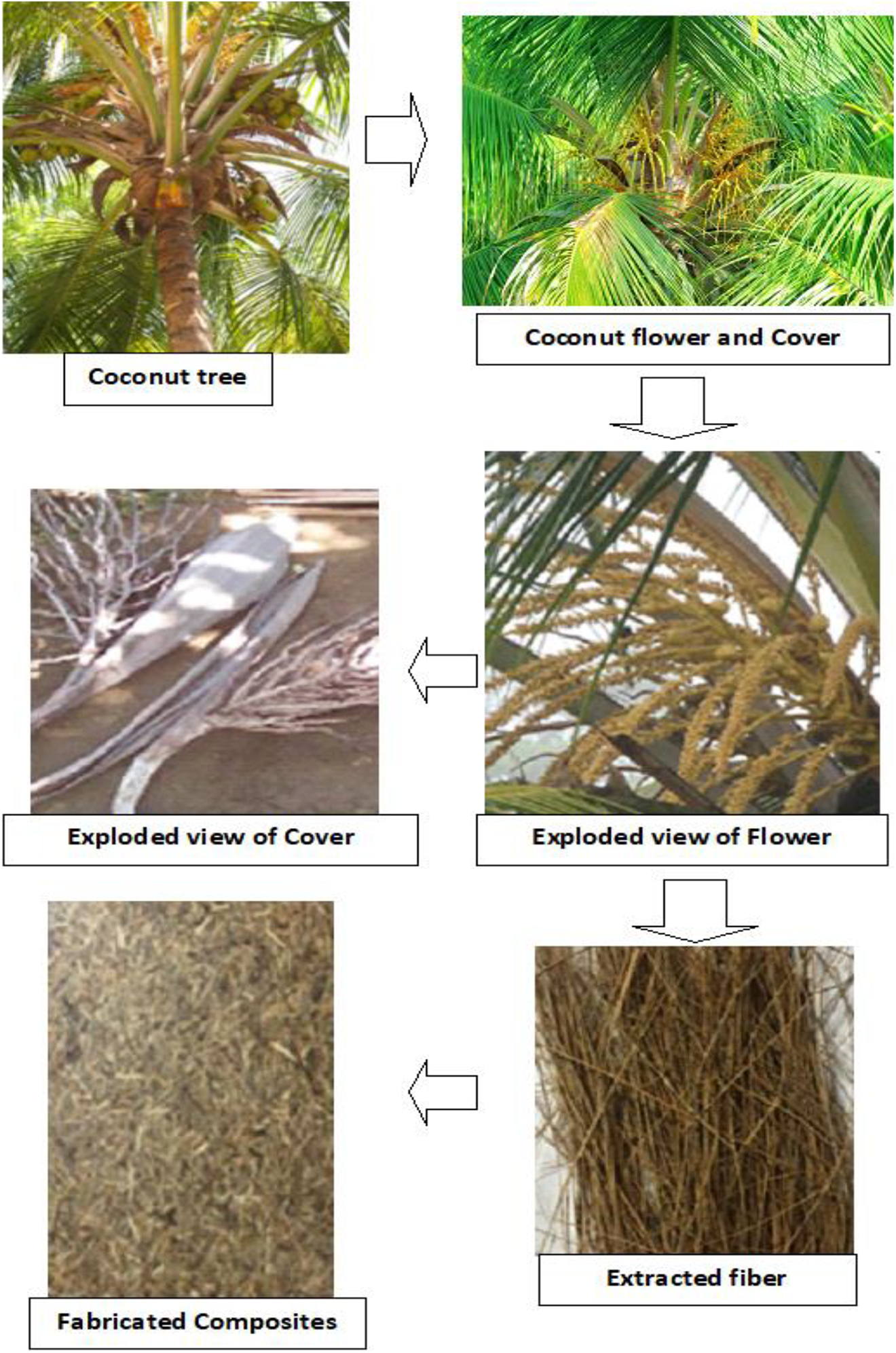
Coconut flower cover fibres and the fabricated composite sample.
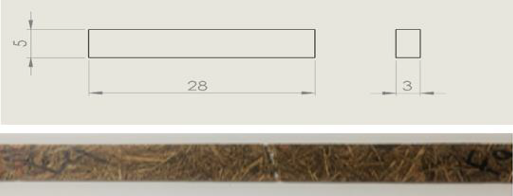
These samples were then subjected to further various tests such as tensile test, flexural test, shear test, impact test and SEM surface analysis. A tensile test was carried out as per ASTM D638 using a standard universal tensile testing machine. The dimensions of the tensile test specimen are thickness = 3 mm, neck width = 13 mm, gauge length = 50 mm and area being 36 mm2. In this test, a tensile force tends to pull the members apart, thereby building tensile stress within the material, which tends to resist the force. The tests were performed on a total of 15 samples of all the three compositions with 5 samples in each composition. Figure 2 shows a broken sample from the tensile test.
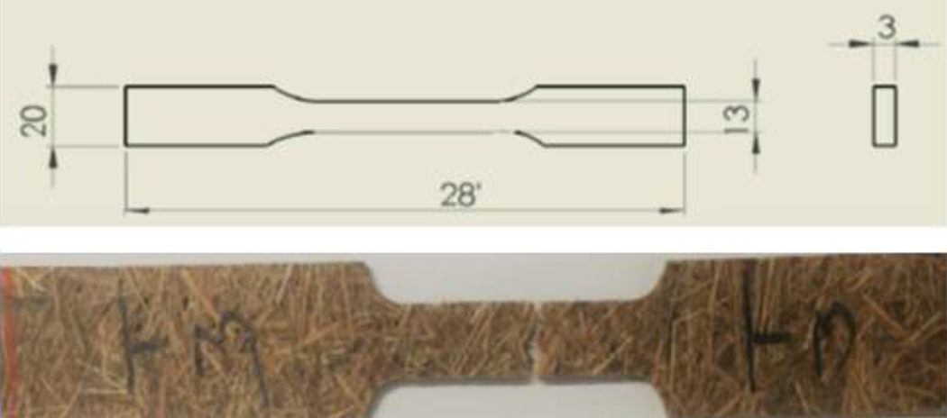
Tensile standard and tested specimen.
Interlaminar shear test was performed on the samples using the ASTM D2344 standard. It was done by measuring the short-beam strength of the composite. This method determined the shear stress that exists between the laminated layers of the composite material. The dimensions of the specimen include a thickness of 3 mm, a width of 26 mm, area of 78 mm2 and a gauge length being 50 mm. Similar to the tensile test, a total of 15 samples were tested with 5 samples from each composition. Figure 3 shows a standard shear test specimen.
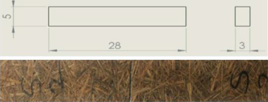
Standard shear and shear test specimen.
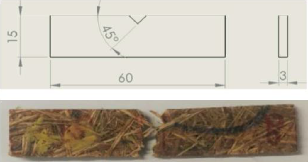
Flexural test was carried out on the samples using the ASTM D790 standard. In the flexural test, when a range of loads acts across the depth, the material experiences both tensile stress and compressive stress. The maximum tensile stress is usually produced at the bottom fibres and the maximum compression stress at the top fibres. The thickness of the prepared specimen is 3 mm, the width being 26 mm and the surface area found to be 85 mm2. Five samples for each composition were taken for testing. Figure 4 shows the flexural test specimen.
Standard flexural and flexural test specimen.
Impact test on the samples was performed by sticking to the ASTM D256 standard. In the impact test, the samples are subjected to sudden impact loads and impact stress is measured. The dimensions of the specimen used are 3 mm thickness and 12 mm width and the surface area is found to be 40 mm2. Figure 5 shows an impact test specimen.
Standard impact and impact test specimen.
Further, SEM analysis was performed on the samples using SEM equipment that has a magnification of 5× to 3,00,000× with a resolution of 3.0 nm (30-Kw high-voltage mode). The vacuum system used for the machine was Turbo-molecular pump (TMP)/Rotary pump (RP) based. The coating unit has an iron sputter coater with a gold target. This method involves in-depth scanning of the surface of the material by focussing a beam of electrons. Broken samples of tensile test, flexural test and impact test were analysed thoroughly to determine the region of strong intermolecular bonding and regions of pores and cavities.
Results and discussions
The shear properties of the composite material measured by interlaminar shear test, tensile and flexural properties observed in the universal testing machine, impact strength measured from impact test and microscopic study done by SEM images are presented and discussed in the following sections.
Tensile strength
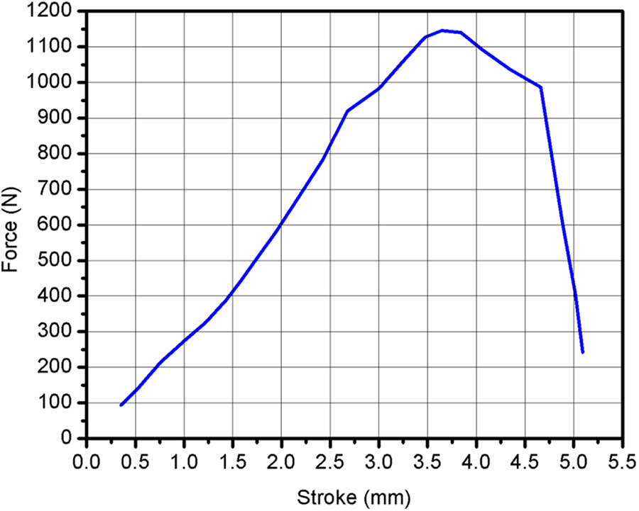
The tensile testing of the fabricated composite material was carried out as per the ASTM D638 standard. Figure 6 shows the force versus stroke observed for the materials tested. The figure illustrates that the application of force increases up to certain level and then falls. The breaking occurs at approximately between 2.6 mm and 2.8 mm of stroke. The maximum force observed for the composite is around 460 N. Further increase in force does not possible. The force–displacement curve does not provide the exact result for the material being tested. Instead, the result may vary by the size of the sample used and the strain rate at which the test being conducted. Generally, force is replaced by stress, S = F/A, and the stroke or displacement, u, is replaced by the engineering strain: e = u/L.
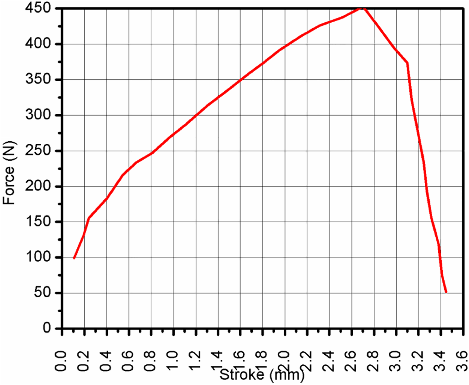
Load versus stroke for the tensile specimen.
The tensile strength of the composite with respect to the increase in weight precentage of fibre is represented in Figure 7. The corresponding average tensile strength of the different fibre weight percentages is 12.17 MPa, 13.82 MPa and 16.72 MPa for 20%, 30% and 40%, respectively. The variation in strength between 20% and 30% is comparatively less than that of 30% and 40% fibre reinforcement. Naturally, the fibres are load-carrying components in fibre-reinforced composite materials. By adopting the proper usage of the fibre content in the composite, the tensile strength of the composite may be improved.
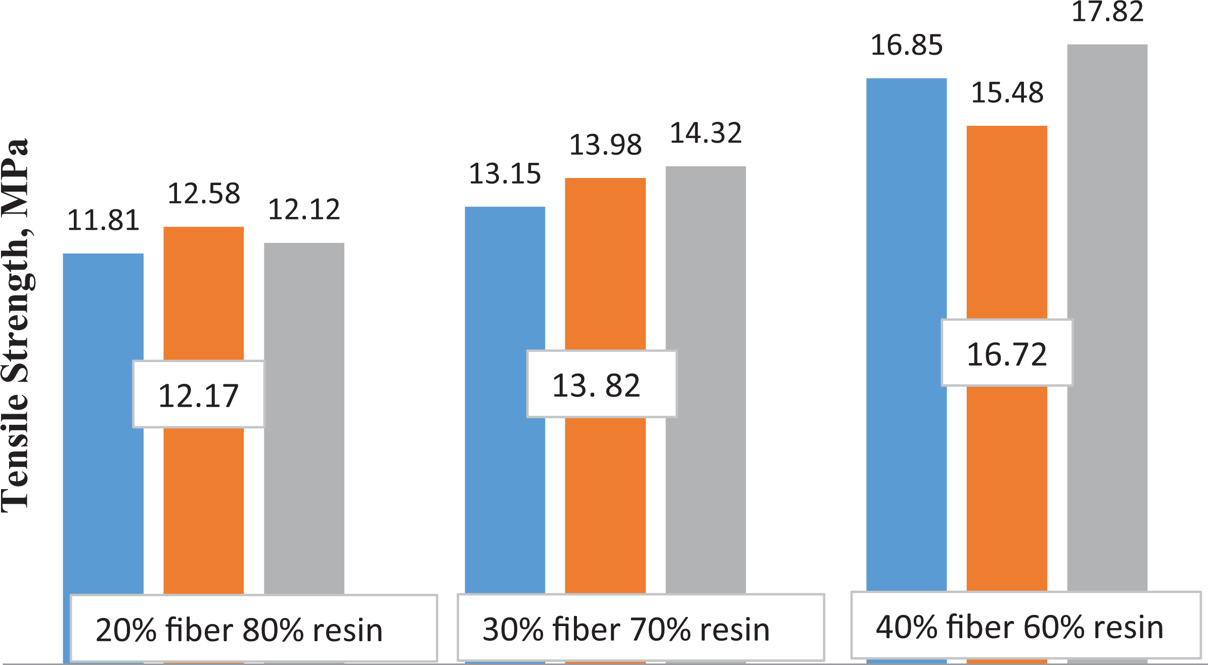
Tensile strength of the composite at different filler variations.
The similar kind of increase in strength was recorded in the past as well. 24 -26 The reason for the better result in the strength is that the fillers carried out the stresses in the loaded material by way ‘elastic matrix – rigid filler’, resulting the perfect reinforcing function. The increasing of filler concentration generally leads to growth in strength until some limiting content. In fibre-reinforced composites, fibres are normally the load-carrying elements, whereas the polymers are the cause of the shape of the composite. This is what exactly noticed in the current results as well. But the strength of the composite decreases when the filler percentage exceeds 40%. This is due to the insufficient distribution of resin and fibres throughout the composites.
Interlaminar shear strength
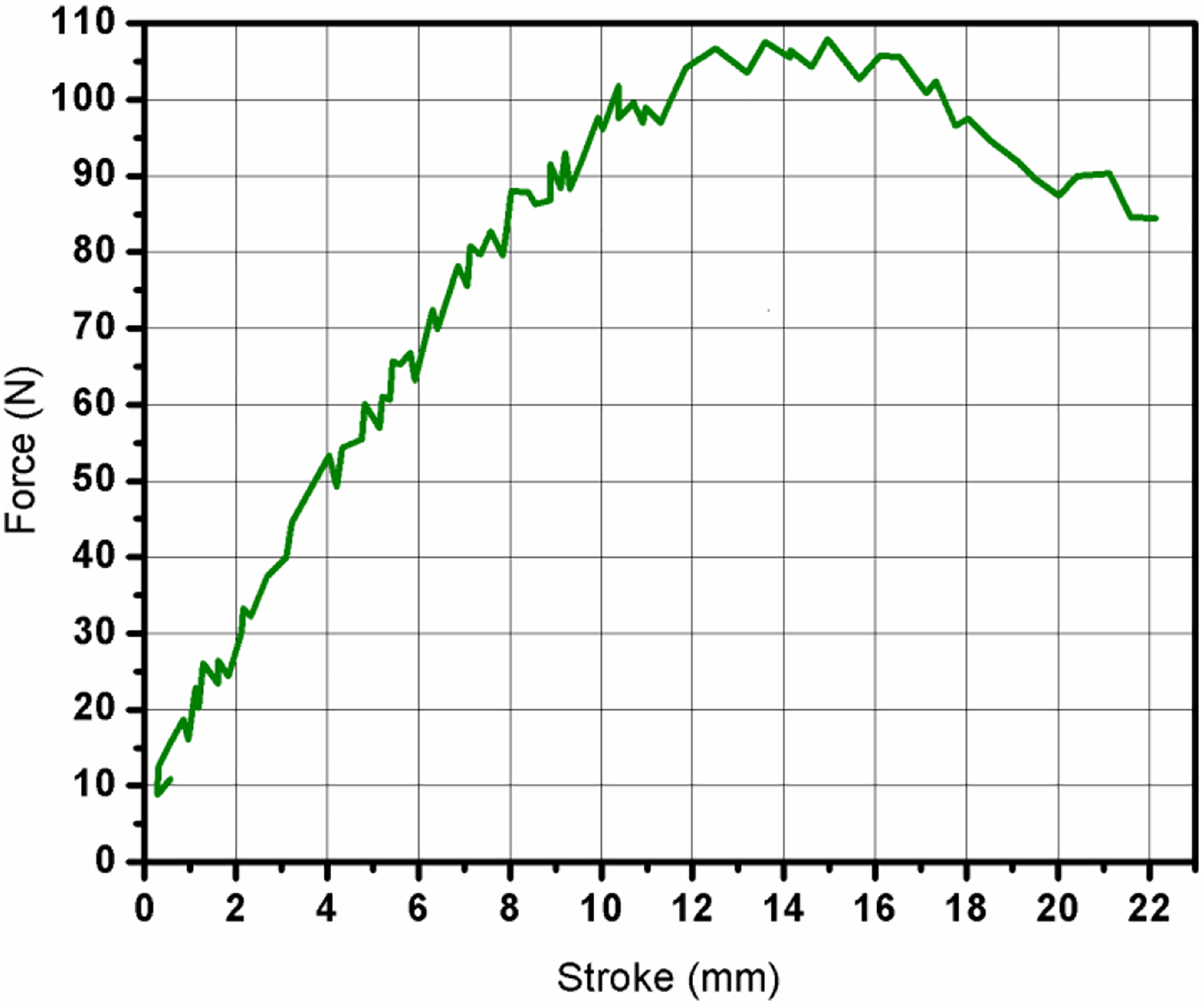
The load versus displacement as a stroke in millimetre observed for the composite during the shear test is presented in Figure 8. Generally, the result of the reinforced composite is in a non-linear pattern. But in the current result, the displacement curve increases linearly and then it tends to fall at the breaking point. For understanding the mechanism or rational of it and for obtaining the real results, the interlaminar shear stress (ILSS) was calculated as presented in the following.
Load versus stroke for the shear specimen.
The ILSS of the composite material was calculated by using the short-beam shear method. After examining five samples in each composition, three best results were considered. The ILSS was calculated by using the following formula:

where ILSS is the interlaminar shear stress (MPa), P is the maximum-recorded load for the sample (kN), B is the breadth or width of the specimen (mm) and T is the thickness of the specimen (mm).
It can be clearly observed from Figure 9 that the value of ILSS increases with the rise in the concentration of the fibre, thereby supporting the claim that the increase in the fibre content results in the increase in strength. Therefore, it can be concurred that by the addition of an appropriate quantity of fibre, the shear strength of the composite material can be increased.

ILSS of the composite at different filler variations.
The current better result is due to a good interface between the matrix and the filler. The high modulus or high strength filler acts as a load-carrying element and enables the resultant composite to withstand the shear load. The major advantage in the reinforcement of fibres is to increase energy-absorbing capability and to transform a base matrix material into a pseudoductile material. It may create a stage of slow crack propagation and gradual failure. This is what evidenced in the current results from ILSS tests.
Flexural strength
Modulus of rupture or the flexural strength of the natural fibre composite was measured by adhering to the ASTM D790 standard of testing. As per the ASTM D790 standard for the flexural test, a rectangular cross-section of the natural fibre composite is subjected to load until it bends. Figure 10 shows the load versus stroke observed for the flexural specimen during the test.
Load versus stroke for flexural specimen.
Five samples in each composition were examined and the best three solutions and the average value were considered for the analysis. From Figure 11, it can be observed that the sample with the maximum fibre content has a greater flexural strength. The maximum flexural load at which the specimen started bending is 0.05, 0.075 and 0.11 kN for 20%, 30% and 40%, respectively.
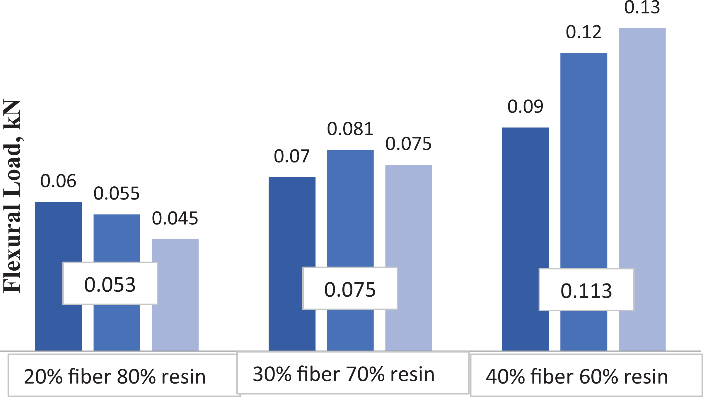
Flexural load of the composite at different filler variations.
Flexural strength of the material is the ultimate of a material when the flexural load is applied. For the reinforced composite material, the flexural strength depends on the base matrix, the orientation of fibres, respective strength of base matrix and filler and so on. In the laminate arrangement, the fibre orientation and the fibre percentage are primary properties affecting the strength of the flexural specimen. Normally for the ductile material, compressive strength is always less than the tensile strength and hence the failure may be initiated as a compression failure rather than the tensile failure. The flexural strength and modulus may be used in the design as the transverse tensile property of the composites.
Impact strength
Notched samples were used in the Izod impact test as per the ASTM D256 standard. The notching procedure was carried out to prevent the deformation of the specimen upon impact. A total of five samples were examined in each composition and the best three average values of the five samples were taken. The result of the impact test is represented in Figure 12. Upon careful inspection, it can be observed that there is a linear relationship between the impact strength and the weight fraction of the filler. The measured impact strength of the composites is 2, 2.95 and 3.66 Joules for 20%, 30% and 40%, respectively. Hence, it can be discerned that the impact strength of the natural fibre composite can be enhanced by espousing the right composition.
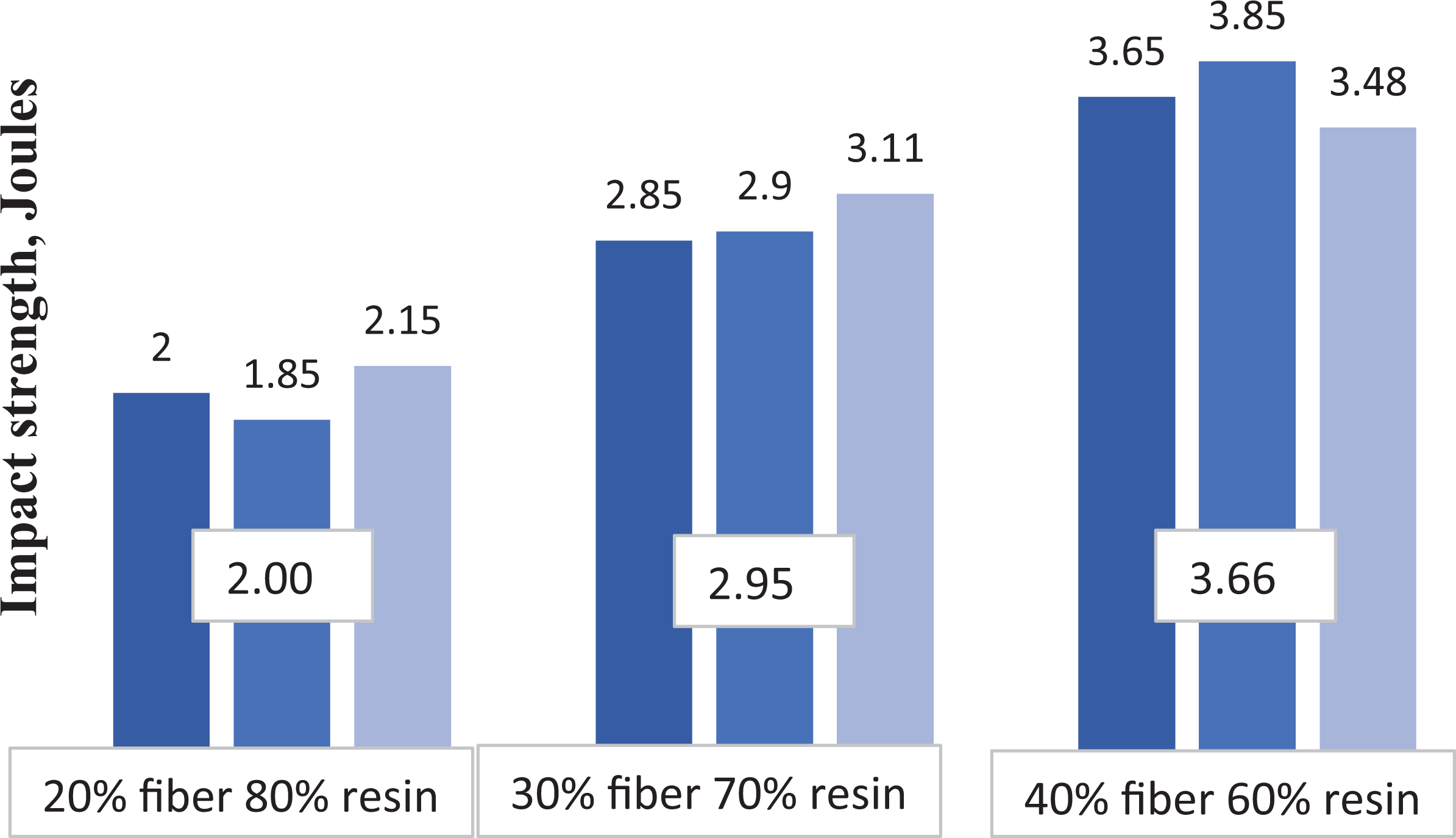
Impact strength of the composite at different filler variations.
Table 1 depicts the consolidated results obtained from the above tests. From the results, it is presumed that the fibre percentage plays a major role in deciding the strength of the composite materials. It is deduced from the results that 40% fibre- and 60% resin-reinforced composite materials give better strength in all aspects.
Tensile, shear, flexural and impact strength observed at various filler fractions.
ILSS: interlaminar shear stress.
SEM analysis
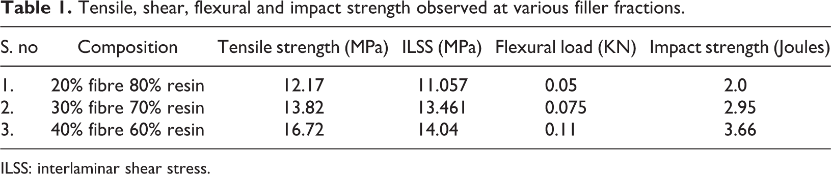
The fractured samples in different mechanical tests were examined in SEM. SEM micrograph of a fractured sample in the tensile test is presented in Figure 13(a) and (b). The images of the fractured surface of the tensile specimen with the maximum filler (40%) show that the fracture occurred at the interface of the specimen. A less number of existences of voids and imperfections was also observed on the fractured surface. This void could be due to insufficient distribution of the matrix material in the composite laminate. On the other hand, it is clearly observed that there is a fibre pull out, which is caused by the application of tensile load on the material. The fracture observed on the specimen is brittle fracture, in which the fibres are cut. There is a fibre pull out occurred owing to the application of tensile load. The fracture mechanism clearly indicates that the bonding between the fibre and resin is reduced, when the tensile load is applied. The SEM micrograph also indicates porous holes, insufficient distribution of the matrix materials and other discontinuities. The reason could be the laminated arrangement of many layers of resin and reinforcing fibres in the resultant composite. These discontinuities may be reduced by adopting any other kind of best manufacturing technique, which may reduce the inconsistency in the material.

(a) and (b) SEM micrographs of a fractured sample in the tensile test.
Figure 14(a) and (b) represents the SEM images of the fractured sample with the maximum filler (40%) from interlaminar shear test. They show the presence of fracture at the interface of the specimen. In the case of Figure 14(a), the presence of voids and pull outs are shown. This void formation is a direct consequence of insufficient distribution of matrix material in the composite. The pull out of the fibre is caused due to the application of a shear load on the composite material.
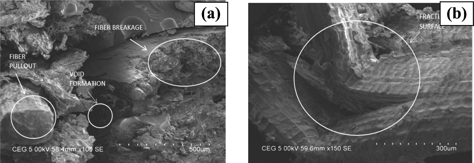
(a) and (b) SEM micrographs of a fractured sample in the shear test.
It indicates the sheared fibres because of the application of the shear load. There is a void found between the fractured surfaces. Tiny holes also found on the surface of the tested specimen. The fibres are not cut or broke into the regular passion; rather, it follows a differential pattern in which the shearing is not uniform. This may be due to the manufacturing of the composite materials and could be avoided by applying the suitable other methods. The high percentage of fibre in the composite makes the material formation valid and good, but it is limited to 40% of filler. Figure 14(b) shows the fracture caused by the insufficient load carrying at the interface. This microstructure was taken at a magnification of 300×, which clearly shows the fracture surface and related irregularities. The SEM images of the samples broken in the flexural test are shown in Figure 15(a) and (b). The flexural test results indicate that there is a fibre fracture but not more violent as discussed earlier. The formation of pull outs is seen in the fractured sample due to the application of flexural load on the fibre. The fractured surface is observed at the interface of the composite. A distinct surface is clearly visible in the image.
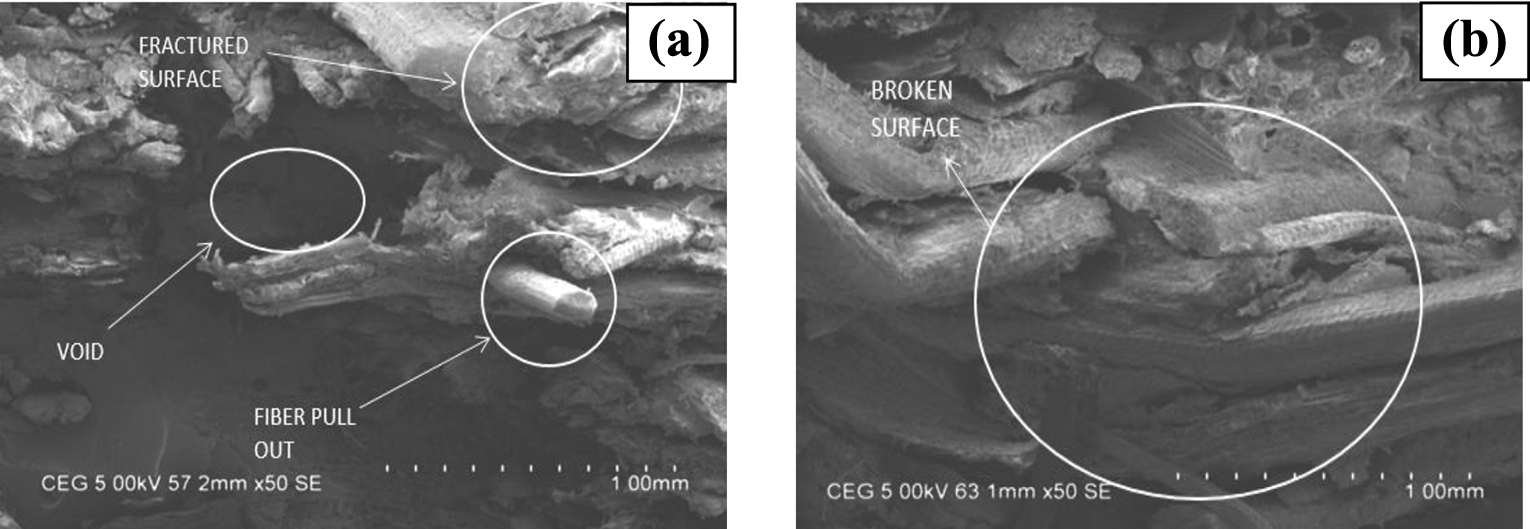
(a) and (b) SEM micrographs of a fractured sample in the flexural test.
Figure 16(a) and (b) shows SEM images of the fractured sample from impact tests. The distinct presence of fractures and voids is clearly seen in the images. It can be concluded that fractures occurred at the interface of the specimen due to the pull outs initiated by the load. The impact specimen indicates the different forms of failure, which entirely due to the application of impact loads. By using proper fibre arrangement, material thickness and sufficient manufacturing process, the strength of these composites can be increased. This kind of material can be used for automobile parts, domestic goods and related applications.
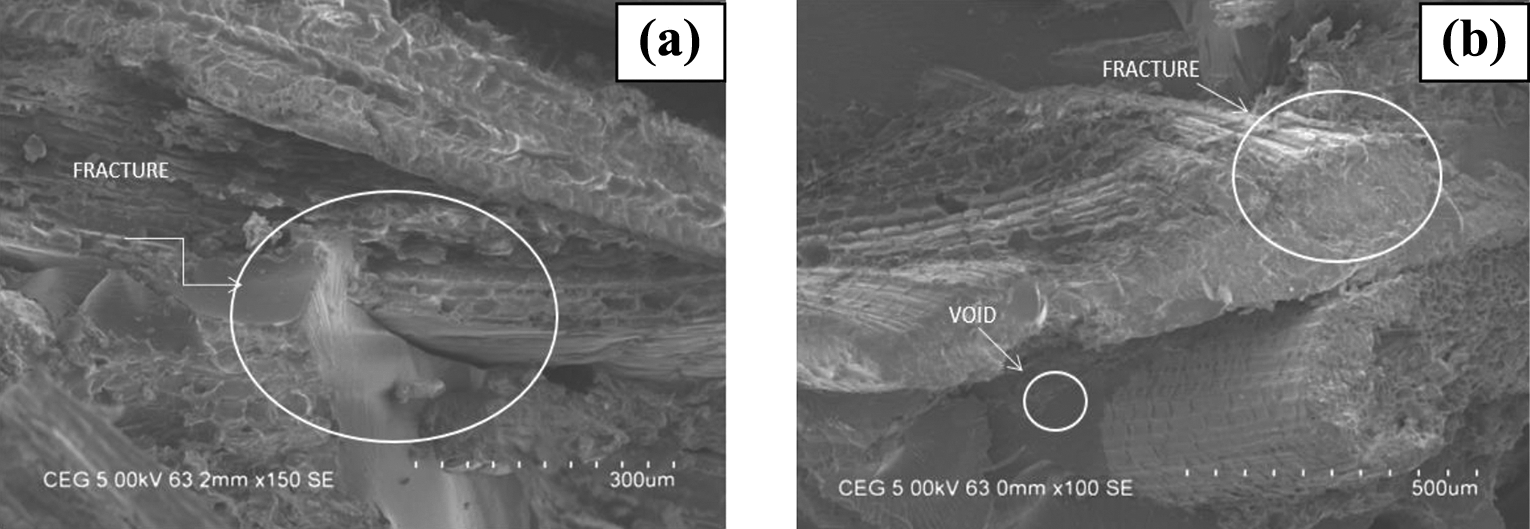
(a) and (b) SEM micrographs of a fractured sample in the impact test.
Conclusions
Based on the experiments conducted on the investigations of coconut flower cover fibre polymer composite, it can be concurred that the mechanical properties of the fibre tend to increase with the increase in fibre concentration.
Coconut flower cover fibre can be used as a viable alternative or a substitute for currently used non-biodegradable materials of similar properties.
Hot compression moulding is a better option for manufacturing of the composite as it reduced the number of voids and air bubbles. But further research is warranted to identify the best manufacturing process which can completely reduce the voids.
It can, therefore, be concluded that coconut flower cover fibre-reinforced polymer composite is a conductive option for industrial purposes especially in the automobile sector.
Footnotes
Declaration of conflicting interests
The author(s) declared no potential conflicts of interest with respect to the research, authorship, and/or publication of this article.
Funding
The author(s) received no financial support for the research, authorship, and/or publication of this article.