
Abstract
This article discusses a BIM Quality Control Ecosystem that is based on Requirement Linked Data in order to create a framework where automated BIM compliance checking methods can be widely used. The meaning of requirements is analyzed in a building project context as a basis for data flow analysis: what are the main types of requirements, how they are handled, and what sources they originate from. A literature review has been conducted to find the present development directions in quality checking, besides a market research on present, already widely used solutions. With the conclusions of these research and modern data management theory, the principles of a holistic approach have been defined for quality checking in the Architecture, Engineering and Construction (AEC) industry. A comparative analysis has been made on current BIM compliance checking solutions according to our review principles. Based on current practice and ongoing research, a state-of-the-art BIM quality control ecosystem is proposed that is open, enables automation, promotes interoperability, and leaves the data governing responsibility at the sources of the requirements. In order to facilitate the flow of requirement and quality data, we propose a model for requirements as Linked Data and provide example for quality checking using Shapes Constraint Language (SHACL). As a result, an opportunity is given for better quality and cheaper BIM design methods to be implemented in the industry.
Introduction
Nowadays there are so many requirements and regulations that buildings have to satisfy, that designing a building became an overwhelmingly complex process. In an average real-estate development project, there are 10–12 disciplines participating and it can easily go higher depending on the complexity of the building. The Whole Building Design Guide 1 lists 30 different domains. Furthermore, regulations are getting more complex year by year and it is an obstructive factor for the design process, according to a research 2 made by the authors, where 90 out of 120 architects were of this opinion.
Manually managing the Quality Control (QC) of the building, from the accessibility requirement of a handle to an acoustic requirement of a window takes an almost impossible amount of effort. According to McGraw-Hill Construction, 3 in 2007, nearly half of architects and owners spent more than 26 h on code checking during a typical project—in some cases even more than 100 h. Interviewing Hungarian actors, these numbers are still realistic under current Hungarian circumstances.
Consequently, there is a great need for automation tools that can support the QC process in the AEC industry. In the present practice, QC automation goes as far as three options: geometrical clash and simple rule checking, quantity checking according to the space program, object level data validation in spreadsheets. Although these methods are improving the quality of the building, there are several pain points that these are suffering from: isolated databases, black-box effect, difficult new rule implementation, limited by IFC structure, etc. The main problem is that there is not a holistic approach that enables finding the global quality optimum of the building, just the local ones. 4 Moreover, the present methods are file based and what one wins on quality improvement, loses on administration, and on file management efforts.
Therefore, a conceptual framework and optimized data flow is proposed as a solution to this whole problem. The solution builds upon the building evaluation method 5 which is a rule-based aggregation method for BIM data. Additionally, a prototype called BIM Dashboard 6 has been implemented, which calculates and visualizes the data according to our evaluation method. During their further research, authors concluded that a systematic approach with a system-wide formalized description is in need for QC processes, which is going to be covered in this paper.
About building requirements and compliance checking
Definition of a requirement
Regarding requirements, firstly, it is wise to understand the exact meaning of the word. According to etymonline 7 the word “requirement” originates from the word “require,” which comes from Old French “requerre” meaning seek, procure, beg, ask, demand which comes from Latin “requirere.” The “re” means repeatedly and “quirere” means query. This is interesting, because it seems from the very early times when they used the word, it was a query or demand that occurred multiple times, which means from the beginning it is a great terrain for automation—of course the technology for such is just given in the latest times.
According to Cambridge Dictionary, 8 it means, “something that you must do, or something you need.” In a design context Wikipedia, says the following: “. . .a requirement is a singular documented physical or functional need that a particular design, product or process aims to satisfy. It is commonly used in a formal sense in engineering design….” 9
Requirements may be categorized in three types: according to the subject of the requirement, according to the data format type of the requirement, and according to the origin of the requirement. The subject of the requirement can refer to the building as a product or to the process of the design or construction. This paper only deals with requirements applying on the building as a product. Requirements targeting processes are out of our scope, whereas it is also a necessary part of a BIM workflow. If the future physical building is taken as a product, the requirements can be interpreted on several levels. It can refer to the building as a whole, it can refer to a concrete structure or element of the building, it can refer to a structural connection or to a material. Every discipline has their own more or less different domain with their different subjects of requirements. It is an important task to consider all of these, if a universal logical model for requirements is desired. According to the description type of the requirement data, it can vary on a large scale. It can be plain text, a concrete value, table of values, calculation formulas, assessment systems, maps, or any combination of the previously listed. In the next paragraph, examples which occur the most in architecture are going to be listed. According to the origin of a requirement, it can be anyone from the direct or indirect project participants: clients, regulators, designers and discipline designers, constructors, facility managers, etc. Distinguishing the origin of requirements is favorable because their frequency of data delivery, their data format of delivery, their data reliability, and their data updating habits can differ, which all has an impact on the quality checking process.
In the software industry the following characteristics are generally acknowledged regarding good requirements: unitary, complete, consistent, atomic, traceable, current, unambiguous, prioritized, verifiable. 10 The AEC industry is a sector with a lot of traditions, hence it does not entirely fit the characteristics of the above listed, whereas it should be a goal to accomplish these characteristics in the future, which needs effort from all project stakeholders including authorities and clients as well.
Data analysis on the main type of requirements used in architecture
Originating from the client, the brief is the document that sets the project goals, constraints, requirements, and initiates the building project. As Koutamanis 4 brings up, a brief is actually an information system, a complex database that has many tables of information that are connected to each other. These tables basically connect requirements to elements and vice versa. Most of the following examples can be part of a brief, while some of them are engaged by only the designers.
Thus, these are the types of requirements that need to be checked during the QC process, in an ideal world, in a fully automated manner. There are many terms used in literature for this action: compliance checking, code compliance checking, clash detection, rule checking, model checking, validation checking, BIM-checking, quality checking, and many more. 12 In this paper, “BIM compliance checking” and “BIM quality checking” are used in synonyms, for naming the BIM based automated quality checking process.
Theories and tools for compliance checking in a BIM environment
A research has been conducted by the authors to see how developed the BIM compliance checking methods are currently. From the academic side, a literature review has been made to see the state-of-the-art theories and solutions developed by researchers. From the practical side, a market research has been made to see what tools are available currently for this purpose and what their exact value proposition and functional repertoire are.
The four steps of BIM compliance checking
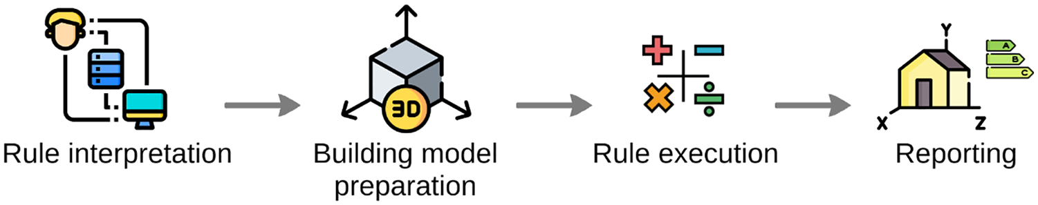
A compliance checking process has four major steps 13 (Figure 1). The first is “rule interpretation.” There are several approaches to translate and formalize the requirements written in natural languages for a compliance checking system: software approach (i.e. Solibri, Navisworks), object-based approach (i.e. CORENET e-PlanCheck), logical approach (i.e. if-then validation, decision table methodology), ontological approach (i.e. RASE, SBVR methodologies). The second step is the “building model preparation.” A BIM model must be built in a way that it enables quality checking. It is important that the structure of the model and the information richness needs to conform with the given quality checking method. The third is “rule execution” or in other words, requirement conflict detection. This is the process when an algorithm compares the designed values to the requirements and creates a pass or fail tag according to the result. The fourth is “reporting” the result, when the results of the previous step are communicated to someone. This can mean a 3D visualization on the screen or a table with the conflicts each line. The purpose of this stage is to give a solid ground for designers to solve these issues. Such a report helps humans understand, follow, and solve these problems effectively.
In this article the rule interpretation and the building model preparation steps are not going to be further discussed. It is assumed that requirements can be formalized to a certain extent. During our literature review several articles, that confirm this assumption, have been found. According to Eastman and Solihin, 15 as experienced in the FORNEX e-Plancheck project, the interpretation step can take as much as 30% of the total time of the whole process. The effort spent on rule interpretation depends mostly on the complexity of the rule. There are examples for compliance checking where the interpretation worked in different domains well: fire safety, acoustics, sustainability, construction, etc. Koutamanis 4 analyzed 10 building briefs and found that only 0%–22% of the requirements were not supported in a BIM environment for QC theoretically. In another case, Bouzidi et al. 16 formalized French Technical Guides to SPARQL language, where they were unable to implement 70% of the rules. Apparently, the solutions and the effectiveness of the interpretation methods vary on a great scale, but it works and automated compliance checking to any extent saves time for the designers and saves money for the client.
The four types of BIM compliance checking
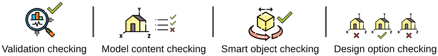
According to Hjelseth, there are four types of BIM Model Checking 12 (Figure 2). The first is validation checking or in other words conflict detection. Clash detection is the most common example of validation checking, while code checking is an example of a popular type of checking, but with limited implementation. The validation checking can be based on multiple sources like codes, standards, contracts, best practice, or by other defined requirements. The second is model content checking, which aims to control the information richness of the model. According to an etalon list it states if all the necessary information is in the model or if there is extra unnecessary information which slows down the process. The third is smart object checking. This is not a posterior checking but a real time adaptive one. A parameter of a given object can be linked to another object’s parameter so when it changes, it automatically refreshes the connected parameter and adapts to the new state. According to our interpretation this type of checking could be possibly a subdivision of the validation checking type. The fourth is design option checking. This means that the BIM model is being confronted to a complex knowledge base and alternative design versions are given according to the conclusions. These types of solutions are at a very immature level in the AEC industry.
Present solutions and tools
The first group of tools that enable automated compliance checking to a certain extent are the briefing, specification, and project database software tools. A benchmark 17 has been conducted in late 2019 with briefing software products18–20 (MasterSpec, Bsdspeclink, dRofus) used in practice. After learning about the capabilities of the software products listed, it seems the market has changed since 2017 and the software is more developed, but the statement is still valid from Koutamanis: “Existing tools are less than generous with their connections to BIM. Most preserve their standalone character, merely allowing content to be imported or linked to BIM. Their information generally remains locked in databases hidden in proprietary software, often replicating data that exist in a model and impeding connections between different kinds of information.” 4
The second group of such solutions are executed by CAAD and BIM programs (e.g. Revit, 21 Archicad 22 ) with extended plugins, scripting, or in combination with Excel. Most of the case studies reported about using Revit plugins for a given discipline requirement checking, for example, for fire protection rule checking.23,24 There are also scripts that generate a TRUE or FALSE value in the BIM software if a certain parameter of an object complies with a requirement value. The simpler version of this solution is when the objects with their parameters are exported to a table and the comparison resulting TRUE or FALSE value is generated in Excel. These solutions are working only with those discipline requirements where the nature of the rules is mostly simple data validation and the rule diversity is low.
The third group of programs are the model checkers. The ones that are mostly used in practice are from the big software vendors25,26 (Solibri, Navisworks), but there are also emerging cloud based solutions.27–31 These solutions provide automated analysis and checking regarding design issues, detecting design deficiencies, and checking the model against rulesets, for example, accessibility, fire protection, etc. Mostly they implement hard-coded functions, therefore the end-user cannot find out how the rules exactly work. It is argued that adding new rules is a difficult task as it can only be custom made by the software developers. 32
In the fourth group, there are research projects with different experimental methods for compliance checking. Most of them are based on the open standard file formats and data schemes governed by building SMART, 33 such as IFC, BCF, and mvdXML. During our scientific review only one freely accessible workflow, called IFCdoc-mvdChecker workflow 34 has been found, with open source or free software and usable documentation. It is going to be introduced in detail in the next section, but the conclusion was that there are two major issues with it. One comes from the limitation of the IFC: limited expression range, difficulties in partitioning the information, multiple description possibilities for the same information, 35 rigorous flexibility, not tailored for query, and analysis tasks. 36 The other is the User Interface (UI), which is not designer friendly.
As a matter of experimental methods, there are two main directions: using Structured Query Language (SQL)13,37–39 or Semantic Query Languages. 40 There are advances in both directions, but it looks like the semantic approach is the more forward-looking one. The use of Shapes Constraint Language (SHACL) is suggested by the authors and other researchers as well.36,41 An example of using SHACL for compliance checking of a BIM database will be introduced later.
Suggested principles of a BIM-based compliance checking
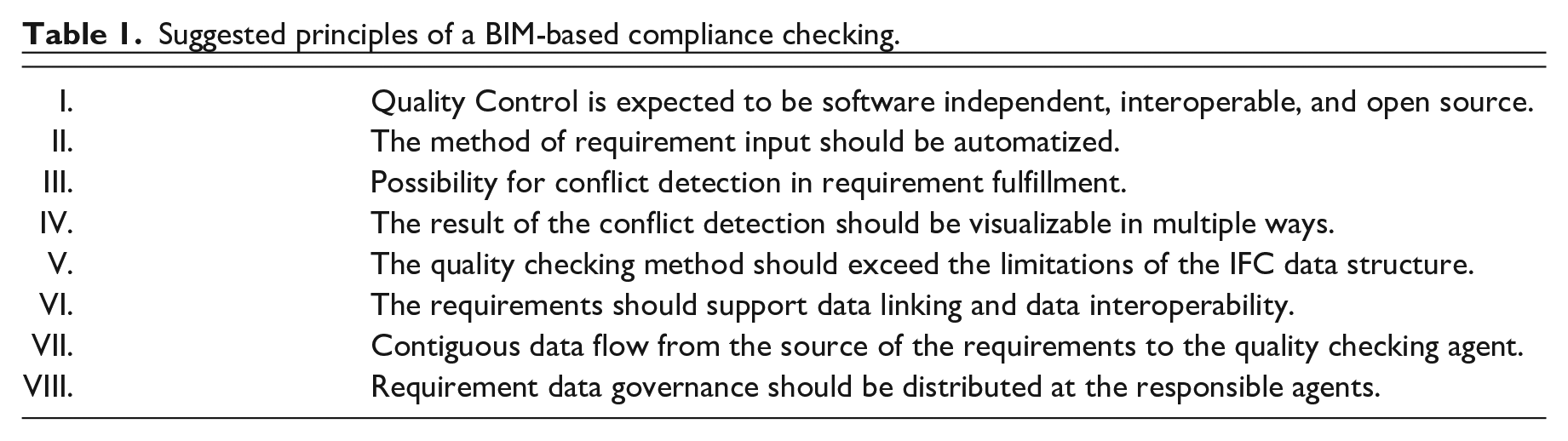
On Table 1, eight principles are proposed, based on the literature review and market research discussed above and modern data management theory regarding data openness and interoperability, 42 that should be satisfied by a state-of-the-art BIM compliance checking system.
Suggested principles of a BIM-based compliance checking.
Principle I. Quality control is to be software independent, interoperable, and available as open source
Quality checking is a sensitive process because there are multiple parties included with great amounts of money, work, and credibility at stake. Therefore, the whole process should be transparent and well understood by every project stakeholder. Hence these parties should use their own digital tools that they know well. Besides the whole requirement information package should stay independent from the stakeholders, consequently the quality checking information should be handled separately from the model, in an open-source way that is supported by existing BIM software. 12 The possibility for localization is also an important issue, as it will facilitate the use of open-source digital quality control methods in smaller languages. 32
Principle II. The method of requirement input should be automatized
If a great amount of work is saved on using automated model checking methods, it should not be given away by spending more time on administration of the requirement parameters. Hence, there should be a way to auto-populate the object parameters with the required values, that will just satisfy the criteria. 43
Principle III. Possibility for conflict detection in requirement fulfillment
The quality checking method should enable conflict detection, including geometrical clash detection and attribute information discrepancy detection. As a result, a pass-or-fail label should be generated.12,44
Principle IV. The result of the conflict detection should be visualizable in multiple ways
The results of a conflict detection should be easy to understand for most of the project participants, therefore multiple visualization methods should be used: 3D data visualization on the BIM model, 2D diagrams, tables, and graphs.6,45,46
Principle V. The quality checking method should exceed the limitations of the IFC data structure
As previously mentioned, the IFC data model is not flexible enough, because it is not designed for various query and analysis tasks. Furthermore, much information used in common industry scenarios is not specified within the scope of the IFC data model. 36
Principle VI. The requirements should support data linking and data interoperability
The practical reason for this point is that the whole QC process should be trustworthy and transparent to every project participant. The theoretical reason is to minimize the necessary data translations between tools, which is one of the basic principles in data interoperability. The Linked Data approach ensures the connectivity of data at various servers and helps to avoid file downloads as a primary mean for data exchange.36,47
Principle VII. Contiguous data flow is expected from the source of the requirements to the quality checking agent
Linking requirement data is a requisite, but not a sufficient premise. It is also important that this data linking is contiguous from the source of the given requirement to the software which executes the conflict detection. 41
Principle VIII. Requirement data governance should be distributed at the responsible agents
Keeping the requirement data up-to-date, giving continuous accessibility to it, sending notification when changes occur and holding legal responsibility for it should belong to the given requirement data responsible agents.4,32,48
Fulfillment of suggested principles on existing solutions
The main goal was to look at the big picture of the above discussed solution repertoire in a comparable manner to see the fulfillment of our suggested principles. Therefore, a comparative analysis has been made on Table 2. Only the results of each solution category are listed, where the software products and services are summed that were mentioned under “Present Solutions and Tools.” Three types of markers were used: yes, no, and partly. Yes, means all of the solutions in that category is according to the given principle, while no means the opposite. Partly means there are solutions that more or less satisfy the given principle.
Comparative analysis on available quality checking solutions by category.
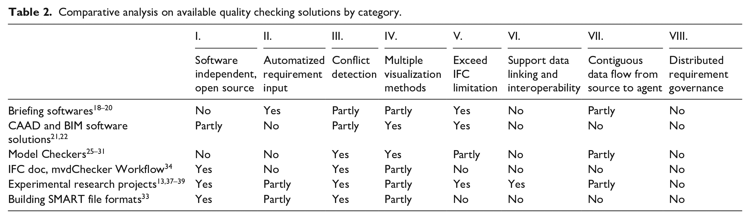
Firstly, there is no solution which satisfies all principles. Secondly, it is apparent that the last three are the main bottlenecks, meaning there is not yet a widely recognized solution based on Linked Data. Also automatized parameter input is only figured out in the minor of the solutions. On the other hand, conflict detection is doable in most cases and there are open-source solutions which are only in the seed phase but started to evolve in a good direction. The same is valid for the visualization methods. There are some promising dashboards and visualization methods for the QC results, but designer friendly and efficient solutions are still awaiting.
To sum up, there is no BIM based QC solution that satisfies our principles and is accessible for offices in a usable and affordable way. Although the quality of basic geometrical and attribute information export has improved and some BIM products started Application Programming Interface (API) data exchange services, there is still no standard for requirement data exchange which could allow the integration of the already existing BIM tools. There is state-of-the-art research tackling this topic and testing prototypes but there is a great need for BuildingSMART, as the leading party in open file formats concerning the AEC industry, to make advancements regarding this topic. In the following, the currently available state-of-the-art QC workflow has been investigated, where the above-mentioned solutions are used.
Open BIM based quality control solutions in context
State-of-the-art open BIM based quality control
The state-of-the-art open BIM QC workflow is shown on Figure 3 based on the literature review and the market research discussed earlier. Only those QC solutions have been put on the workflow diagram, that are thought to be of a consensus in the literature and which have usable and accessible solution for a given function. There are two types of blocks. One is the source of requirements, who are the responsible agents, namely the client, the authorities, and the designers—shown by icons—and the other is the QC solution block. In the following, these blocks are explained one by one.
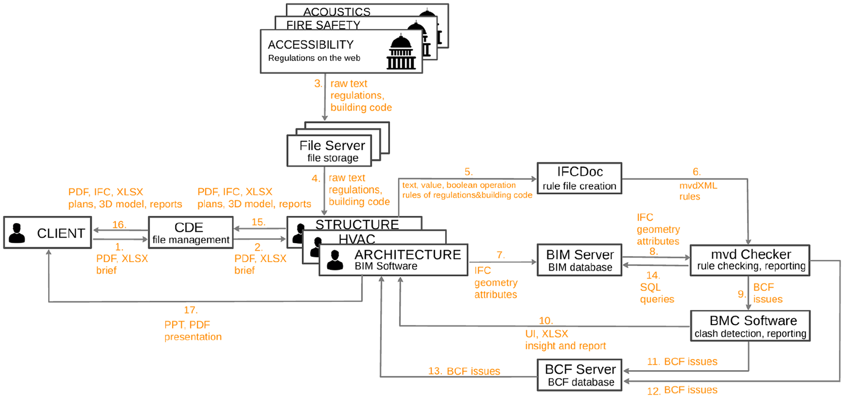
State-of-the-art open BIM based quality control.
Blocks of the state-of-the-art quality control
Summary of the state-of-the-art solutions
Overall, this workflow is still mainly file based, although these are open standard formats such as IFC, BCF, mvdXML. It enables BIM model-based QC, but it requires IT experts as well, who can see through the software environment and are familiar with the above-mentioned open file formats. It concentrates only on the part of the design process that is beyond the designers and does not provide a framework for handling requirements throughout the whole process. Finally, as shown on Table 2 at the “IFCdoc, mvdChecker Workflow” line, this QC workflow does not meet principles V–VIII and only partly capable of automation.
Suggested open BIM based quality control ecosystem
Most research regarding this topic focuses only on a few aspects of the BIM QC workflow, for example, on regulation to rule conversion methods, analyzing and testing new technologies, or creating new pieces of software. Even if their research scope involves the context, usually their solution deals with only a certain discipline requirement type of the QC problem. For example, fire safety, with only the related software and user environment. Therefore, from the industry point of view, these are partial successes, but from a universal BIM QC point of view, these approaches are not wide enough. Hence the concept “BIM Quality Control Ecosystem” has been introduced, which deals with the QC solutions, the involved parties, and their relation to the whole process at the same time.
An ecosystem is suggested on Figure 4, that corresponds to our previously stated principles. As a result, the QC process will be of better quality, with less administrative workload on the project participants, enabling BIM design methods to become cheaper and more widespread.
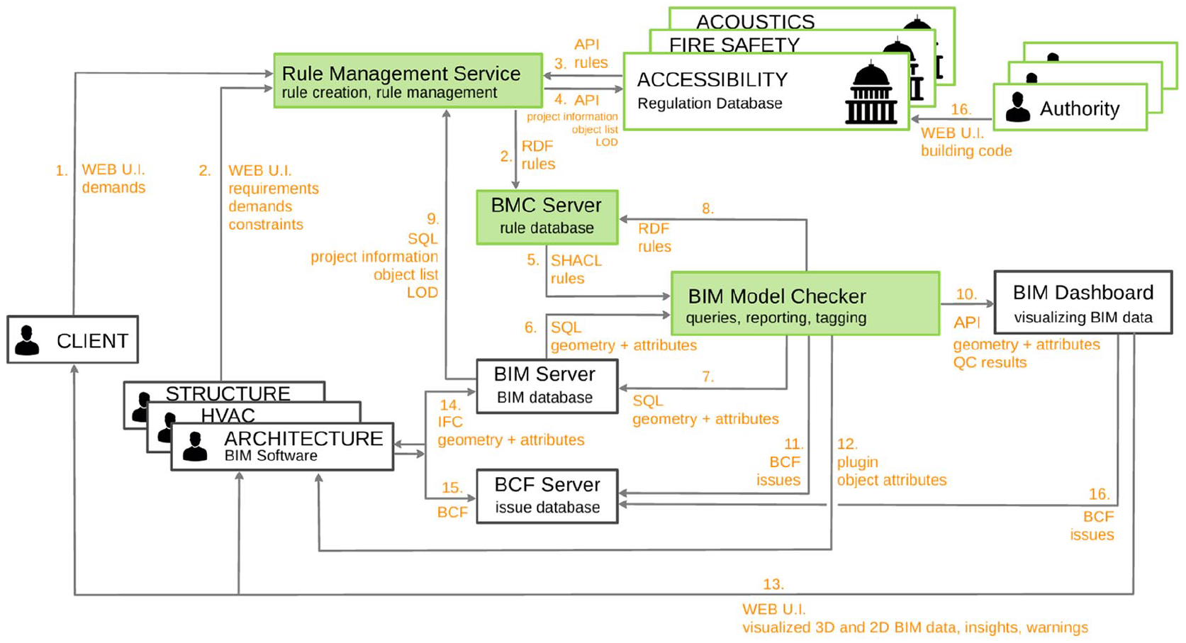
Suggested open BIM based quality control ecosystem.
In accordance with the above, our ecosystem is a modular and open system, where BIM functions are separate entities. This way any module is replaceable and the software in use can be freely chosen.
Every party who establishes requirements are responsible for them and they must govern them throughout the project. Moreover, there is a Linked Data connection between these parties’ requirements all the way to the quality checking tool. This means a lot of administrative redundancies and extra human-to-human communication can be saved, while the chance of making mistakes is reduced.
The ecosystem relies on three databases: the first is the BMC server, where all the quality checking rules from all different sources are collected. The second database is the BIM server where the design models are stored. The third one is the BCF server where the issues concerning the design process are stored. One can input data into these databases and can query these databases with a suitable software tool. While all these databases should avoid redundancy, should be based on linked data and should track changes, this paper only focuses on the BMC server and the requirement information in our conceptual example. Regarding the other two databases, it is desirable to build upon tools which are already used and can be adapted to the ecosystem while corresponding to our principles. That is why the BIM Server 52 and the BCF Server 55 have been applied. It was also desirable to enable Transparent Design, 56 which means any requirement conflicts can be traced back to their sources at any given point of the design process.
Modules of the suggested ecosystem
Four types of modules have been differentiated: data generation, data storage, automatic quality checking, and BIM data visualization tools. According to our findings these should be separate entities. The main concept is that the data generation modules such as the Rule Management Service and BIM Software are sending the generated data to independent project databases. The rule checking software accesses these databases and executes the rule checking algorithm. The results of rule checking can then be sent for further processing, to the BIM dashboard, the BCF server or the BIM software.
There are three main advantages of this modular concept. The first is that there is no need for one complex software that handles every task, as it threatens the users with vendor lock-in, expensive customizations, or a steep learning curve. The second advantage is that any custom software can be used which fits the purpose of the given module. For example, any kind of BIM software that fits the designers’ needs or any kind of data server, no matter if it is located in the cloud or it is a local one, works within the system. Furthermore, any kind of rule checking or dashboard software that is trusted by the project participants or suits the client’s need can be used. The third benefit is that the modules and data connections among them can be upgraded separately. Consequently, upgrading can be done one by one, and does not have to change the whole ecosystem simultaneously. The explanation of the modules is the following.
Once the rules are added to the regulation database, they are searchable through the web. In every building project, designers should download the rules that are relevant for their exact project to the project rule database on their BMC server. As a result, all the requirements to be fulfilled from the authorities are in one place and are trackable back to its source.
The idea of the regulation database conforms to the theory of distributed building data. 41 Werbrouck et al. even tested a technical solution in this topic which looks promising. They used the Solid ecosystem 59 to make connections with proper authentication between the distributed building project data. After building up the connection they used SHACL to collect the proper data they wanted. The same process could work in our case as well. The authorities and the BMC server would be the points to be connected through Solid, and the requirement data would be distributed among them.
Summary of the suggested ecosystem
This ecosystem is designed according to all our BIM-based Compliance Checking principles and tries to overcome the weaknesses of the existing solutions as presented. A critical factor of this conceptual framework is the interoperability of requirement information. Hence, authors propose a data structure for Requirement Linked Data.
Proposed data model for requirements
Our suggestion is formalized as an ontology, since interoperability and self-description are core features of Linked Data, to be utilized here. The usage of Linked Data is growing significantly year by year. In the EU, Core vocabularies are promoted for describing Persons, Businesses, Locations, Criteria, etc. 61 Further ontologies or RDF schemas are widely used for metadata provisioning (Dublin Core 62 ), describing persons (FOAF 49 ), metrics and measurements (QUDT 50 ), etc. In fact, BIM also follows these principles, though IFC is not defined primarily in RDF. For example, the BIM Ontology 63 helps to structure semantically the terminology of buildings.
In 2018, the UN World Data Forum also voted for the linked-data approach in its guide for data governance. 64 Hence, the solution suggested here is the BIMReq ontology 65 (Figure 5), which enables rich semantic description of requirements, thus leverages intelligent management, reasoning, and visual evaluation of building requirements. BIMReq offers descriptions for the following concepts: regulations, requirements, and evaluations.
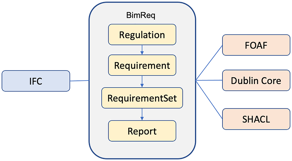
Key elements of the BIMReq ontology.
Regulations are described primarily with the metadata necessary for identification using Dublin Core terms. In this way the date, creator, name, and identifier of the regulations can be provided by the regulator together with the link to the full regulatory text. Furthermore, subject classifications may be given by discipline type and regulated object type. Optionally, a full SHACL 66 expression may be attached translating regulation text into compliance checking rules. Ideally, the Regulation Linked Data would be maintained and made accessible by the regulator.
The next key concept is requirement, which can be grouped into requirement sets and can be bound to construction projects and IFC models. Requirements may be raised by the client or a designer but may also be derived from regulations. In the latter case the requirement connects the regulation to selected parts of the IFC model and may also concretize the expected measurements. Requirements should also contain descriptive metadata, minimally the creator, creation date, and short description. Subject categories can help filtering requirements by object type, object location, or discipline type.
There are several possibilities for automated compliance checking, depending on the tools and formats used in the project. In case of IFC XML, Xpath expressions can be created, in case of plain IFC custom scripts may do the checking, while in case of IFC OWL one can use SHACL (an example is given later). From all these possibilities SHACL is the most promising, as it provides a full validation framework and the most readable format.
Requirements may be evaluated multiple times by multiple people. An evaluation contains the evaluator, the date, and the result, which may be an objective result of a calculation or a subjective ranking or a pass-fail stamp. However, it is assumed that many of the requirements can be checked against the BIM model based on rules generated from the requirements.
As an example, a thermal transmittance requirement is defined on a window:
ex:req01 a bimreq:Requirement;
rdfs:label “Window Requirement 01”@en;
dc:description “Thermal transmittance for the A type windows must be below 1.8”@en;
dc:creator ex:RegulationsOffice;
dc:created “2019-05-26”^^xsd:date;
dc:source ex:A5434Document;
dc:subject “Thermal Transmittance”@en;
bimreq:target ifcowl:IfcWindow;
dc:valid “2021-01-01”^^xsd:date;
Based on this requirement, one can easily generate a BCF comment to pass forward to BIM applications. Furthermore, one can use SHACL to auto-generate compliance reports for the BIM model. The shape expression for the requirement above could look like the following:
ex:WindowShape
a sh:NodeShape;
sh: name “Thermal transmittance checking on windows”@en;
sh:targetClass ifcowl:IfcPropertySingleValue;
sh:filterShape [
sh:property [
sh:path ( ifcowl:name_IfcProperty express:hasString );
sh:hasValue "ThermalTransmittance";
]
];
sh:property [
sh:path ( ifcowl:nominalValue_IfcPropertySingleValue express:hasDouble );
sh:datatype xsd:double;
sh:maxInclusive "1.8"^^xsd:double;
sh:severity sh:Warning;
].
SHACL reports can then be transformed into plain text reports, BCF comments, or spreadsheets, which can either be read by humans or imported into BIM tools for further processing.
Conclusions and future research
It has been discussed that there is a great need for improving the QC process of a building, since manually managing so many requirements is unfeasible and error-prone. After the current software products, workflows and experimental technologies have been analyzed, authors articulated eight principles that are thought a state-of-the-art BIM based QC ecosystem should possess and a conceptual framework has been designed in compliance with these. A logical model has been proposed for the requirement data structure in Linked Data representation which can provide data interoperability for various software tools enabling a large variety of QC management solutions.
As a result, the whole QC process becomes transparent and more understandable for all stakeholders, causing less errors, less conflicts, and less monotonic tasks. Authors suggest a proper distribution of requirement data governance in accordance with responsibilities. Authorities maintain a set of machine-readable regulations, which are easy to re-use in construction projects via Linked Data connection, while designers may compile and re-use requirement profiles for typical building projects. Finally, the file-based communication between the client and the designers has been shifted to information-based, using open and Linked Data formats.
New methods and tools were suggested, as modules of the proposed ecosystem, for automated checking of requirement fulfillment, reporting and visualization of quality checking results. A possible missing piece in the tool line is the software support for generating Requirement Linked Data.
This ecosystem opens gates for new functionalities and new custom developed solutions. A promising direction in the future is extending the time frame of this ecosystem to the full lifecycle of the building. During the construction phase, product changes could be validated or in the operation phase manufacturers could be tendered automatically for refurbishment according to the given requirements, saving money for the investors and speeding up the process. Also, it would be interesting to see how this ecosystem could work with new distributed technologies such as the Solid Platform 59 or Blockchain technologies. 67 Moving toward a data-driven design methodology, may trigger many exciting new developments in the next decades.
Footnotes
Declaration of conflicting interests
The author(s) declared no potential conflicts of interest with respect to the research, authorship, and/or publication of this article.
Funding
The author(s) disclosed receipt of the following financial support for the research, authorship, and/or publication of this article: The research reported in this paper and carried out at BME has been supported by the NRDI Fund (TKP2020 IES, Grant No. BME-IE-MISC) based on the charter of bolster issued by the NRDI Office under the auspices of the Ministry for Innovation and Technology.