
Abstract
Today’s architecture increasingly features complex, free-form buildings, facilitated by parametric design. Yet, these forms face significant challenges. In the current global energy crisis, early-stage optimization of free-forms for energy performance is essential. Also, digital fabrication, often required for such complex geometries, should be integrated into their form-finding. Furthermore, the distinct aesthetics of free-forms demand attention during form-finding. However, there is a lack in integrating these objectives in form-finding of free-forms. This paper presents and applies a comprehensive multi-objective optimization framework for the form-finding of a free-form building. Case study results show improvement in minimizing façade surface area, minimizing incident solar radiation in summer, and maximizing it in winter by 2.25%, 1.7%, and 1.4% respectively, compared to baseline form. Additionally, all façade panels are flat, and aesthetics are considered. These findings underscore the framework’s potential to generate energy-efficient, rationalized, and aesthetically appealing parametric forms that meet the demands of contemporary architecture.
Keywords
Introduction
Computation-based approaches in design have gained popularity in recent decades, becoming essential tools in the architectural field. 1 Unlike traditional manual methods, these computational approaches empower architects to explore more complex and free-form designs through digital means. Among them, parametric design stands out as a transformative approach. 2 The emergence of parametric design has shifted architecture practice from following a traditional, representational process to a complex, generative, digital workflow based on simulation and evaluation. 3 In this workflow, architects define and set design parameters and control procedures in order to find the appropriate form for a given design problem, 4 a process known as form-finding. In contemporary architecture, form-finding is quite essential for meeting the high standards and demands of the current modern world. It facilitates the exploration of numerous design possibilities quickly and efficiently, offering innovative, customized, and highly responsive architectural solutions that adapt to various contexts and functional demands.
However, the key challenge here lies in setting the appropriate design objectives from the early form-finding process, which is crucial for the success of an architectural design. While architecture today encompasses diverse priorities and design objectives, such as energy performance, structure performance, acoustic performance, feasibility of digital fabrication, aesthetic appeal, etc., many opinions can agree that energy performance, digital fabrication, and aesthetics are among the most essential. These objectives not only are highly relevant during the early stage of form-finding, but also are universally applicable in any design case regardless of their nature or context.
In addition to that, the importance of energy performance, for instance, has become paramount in response to the global energy crisis, underscoring the need to prioritize energy performance as a design objective in buildings’ designs 5 from the earliest stages of building design. 6 Similarly, digital fabrication plays a pivotal role in executing today’s contemporary complex designs, 7 making it essential to consider as a core aspect in buildings’ designs and set design objectives related to it. 8 Furthermore, the non-standard aesthetics associated with the current complex free-form building designs make aesthetics crucial consideration in buildings’ designs, especially that high performance designs may not always be as good with respect to aesthetics. 9
Despite the importance of these objectives, they are rarely integrated into the form-finding process. In previous studies addressing the topic of multi-objective optimization, most of the studies have only addressed the energy performance objective, as found in.10–18: Other studies have added to that, including aesthetics together with energy performance, as found in.19–22: While other studies have considered the digital fabrication constraints and objectives through performing geometry rationalization, as found in.23–28: To our knowledge, little to no studies have addressed multi-objective optimization concerning the three objectives. Therefore, we can see that there exists a main research gap which is the lack of integration between these objectives in the form-finding process.
In a previous study by the authors, a review for the form-finding of architectural parametric forms was conducted.
29
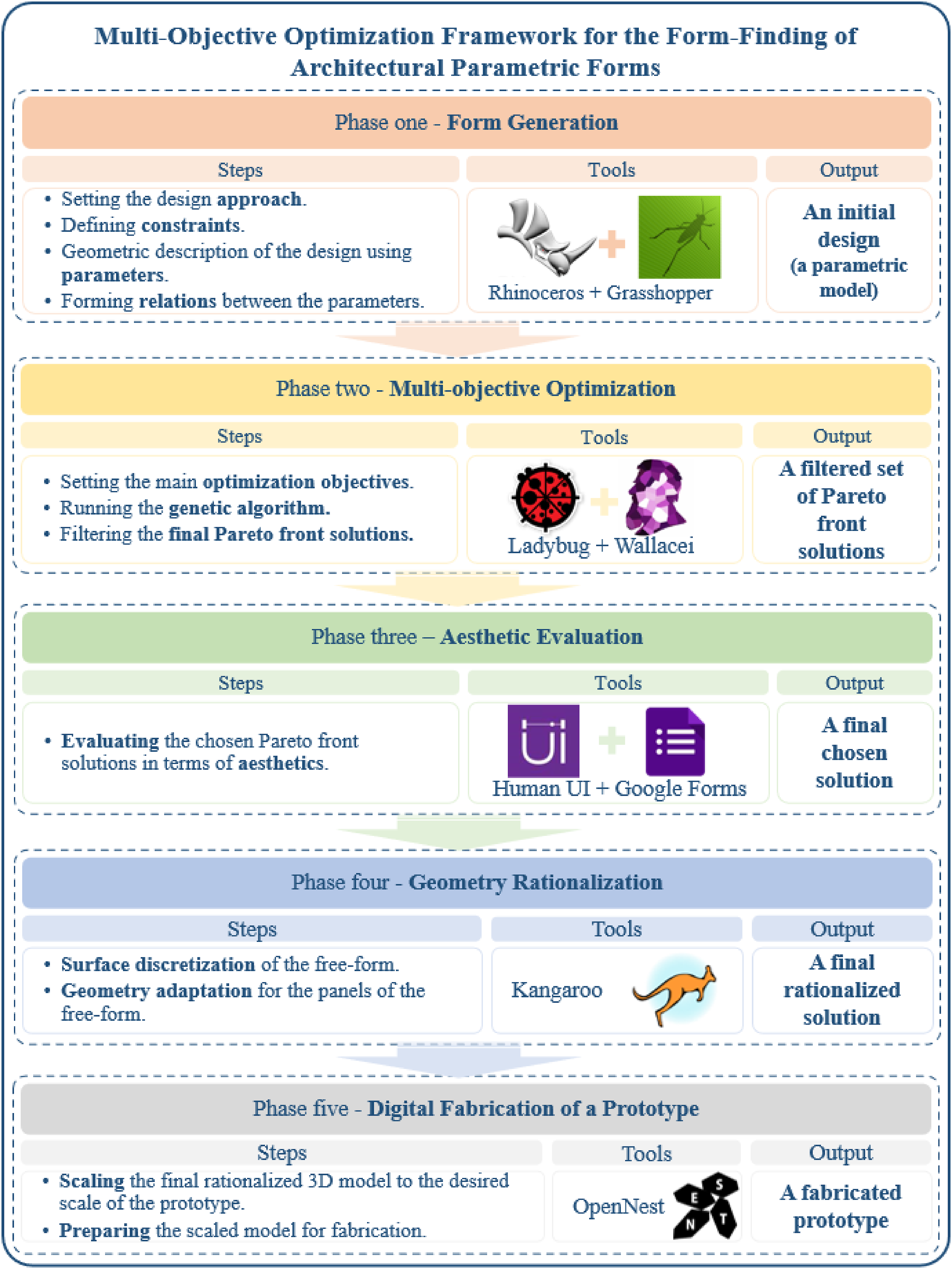
Results of the review showed that there was not a comprehensive framework that takes care of all three aforementioned objectives at once, which could be essential for producing rational, sustainable architectural solutions. This is why a new multi-objective optimization framework was proposed (see Figure 1). The framework encompasses five phases. All phases of the framework are implemented within McNeel Rhinoceros 3D (Rhino) and its virtual programming environment, Grasshopper (GH), owing to their versatility, accessibility, and widespread use in architectural modeling. In addition, some GH embedded plugins are used, such as Ladybug, Wallacei, Human UI, Kangaroo, and OpenNest. Each of the five phases is briefly explained in the following: • The first phase of the framework is Form Generation. In this phase, the main design approach/approaches is/are decided, constraints are defined, design geometric features are translated into design parameters, and relations are set between those parameters in order to govern the generated forms. GH for Rhino is used as the main parametric modeling tool. The outcome of that phase is an initial design, or in other words a preliminary parametric model. This model provides a foundation for further refinement and development in subsequent phases. • The second phase is Multi-Objective Optimization. It starts by setting the main optimization objectives (specified energy performance and digital fabrication objectives), followed by setting and running the Genetic Algorithm. Then, filtering the obtained final set of Pareto front design solutions to find the ones that give the best trade-off between the specified objectives. Wallacei for GH serves as the main optimization tool to handle the multi-objective criteria, while Ladybug for GH conducts energy performance simulation. The output of that phase is a filtered set of Pareto front design solutions. • The third phase, Aesthetic Evaluation, involves evaluating the chosen Pareto front design solutions in terms of aesthetics based on predetermined aesthetic judgement parameters,
30
such as building shape, symmetry, proportion, and rhythm. This evaluation is conducted through the Human UI plug-in for GH, combined with an embedded Google form for collecting the evaluation results. The outcome of this phase is the selection of a final design solution. • In the fourth phase, Geometry Rationalization, the free-form design undergoes surface discretization into any desired geometric configuration. Then, geometry adaptation for the resulted free-form’s panels is applied in order to adjust these panels to be applicable with the intended fabrication technique and material (subtractive fabrication using a standard laser or CNC machine, Medium-density fiberboard (MDF) material sheets are used for the prototype). Here, two things are mainly considered in the panels, which are dimensions and planarity. Dimensions of the panels should be compatible with the dimensions of materials and machinery. In addition, all panels should be flat as required for standard CNC machine and the used unbent material. The Kangaroo plug-in for GH is employed to ensure these criteria are met, yielding a final rationalized design solution as the output of this phase. • The fifth and final phase is Digital Fabrication of a Prototype. The design model is scaled into the desired scale of the prototype (optional step if only selected parts or components from the original model are used). Then, the selected part or the scaled model is prepared for fabrication. OpenNest GH plug-in is used to transfer and pack the panels into material sheets, optimizing the panel packing onto the sheets. The result here is a fabricated prototype of the final design. Besides, any fabrication challenges encountered are resolved and documented in that phase. Multi-objective optimization framework for the form-finding of architectural parametric forms. Source.
29
We can see that each phase of the framework builds sequentially upon the previous one. Outputs from each phase seamlessly transition as inputs to the subsequent phase. For instance, the initial model generated in the Form Generation phase becomes the foundation for Multi-Objective Optimization, and so on. This progression continues through each stage until the attainment of the final design and its fabricated prototype. This structured workflow ensures a streamlined transition from the initial form to the final fabricated prototype, enabling a cohesive, comprehensive form-finding process. For further details on the framework phases, you can refer to the original paper introducing this multi-objective optimization framework. 29
In general, the framework is mainly intended to be easy to use, flexible enough to fit into any architectural project, comprehensive, allows for interactive and informed collaborative decisions, and affordable enough for architects without a background in programming. In addition to that, the anticipated outcomes of the framework on the parametric form-finding process included the following points: • Fabrication-aware design: Considering fabrication between the approaches of generating the initial form of the building can potentially enhance later design implementation. • Comprehensive optimization: Optimization is extended to include fabrication objectives together with energy performance, which broadens the perception of architectural design. • Aesthetically appealing form: Selection of the final design according to users’ aesthetic preferences can enhance the aesthetic quality instead of relying solely on designer’s intent. • Effective rationalization: Adding rationalization during the early form-finding can significantly cut the time and effort used in modifying designs for fabrication in a later stage. • Error free and cost-effective fabrication: Rapid prototyping during early form-finding can inform design decisions, ensure the applicability of design and evaluate its feasibility, avoid errors in the final fabrication of the building.
The previous study 29 has only introduced this new framework based on an analysis of a comprehensive systematic review; however, no practical application was conducted. Given this, the framework would greatly benefit from being tested in a practical application on a case study to validate its effectiveness, demonstrate its potential and limitations within architectural practice, and identify opportunities for improvement and recommendations for future applications. Therefore, the objective of this paper is to attain these goals by applying the framework to a practical case study and analyze its outcomes.
The research is organized as follows: First, the objective and the methodology of the paper are explained in detail. In the subsequent section, the paper conducts a case study which is defined in the first part of the section, showing the criteria for its design, the selected location and climate, and the building model description. The second part of the section shows the application of the used framework on that case study, detailing all the conducted steps and procedures for each of the five phases. Then, the results of the framework application on the case study are further discussed for each phase. Following this, the effectiveness of the framework is demonstrated by conducting a comparative analysis between the final designed form and the baseline form in terms of the predefined design objectives. The research then lists the potential and limitations of the framework and gives some key insights for advancing architecture by enhancing contemporary architectural forms. Finally, conclusions and recommendations for future work are presented.
Objective and methodology
Objective
The main objective of this research is to give key insights regarding advancing architecture by enhancing contemporary architectural forms through using comprehensive multi-objective optimization frameworks in the early form-finding. This objective can be achieved through the following goals: • Validating the effectiveness of the used multi-objective optimization framework. • Showcase the potential and limitations of the framework in architectural practice. • Come up with potential improvements and recommendations for future use of such a framework.
Methodology
The research follows a combined methodology of theoretical, practical, and analytical approaches, as illustrated in Figure 2. It begins with a theoretical approach, presenting parametric design and form-finding, and their relevance to contemporary free-form buildings. This is followed by an overview of the used framework, outlining its key concepts, main components, and anticipated outcomes. This was all presented in the previous introduction section. The framework is then applied to a case study, presented in five steps. Methodology of the research. Source: Authors.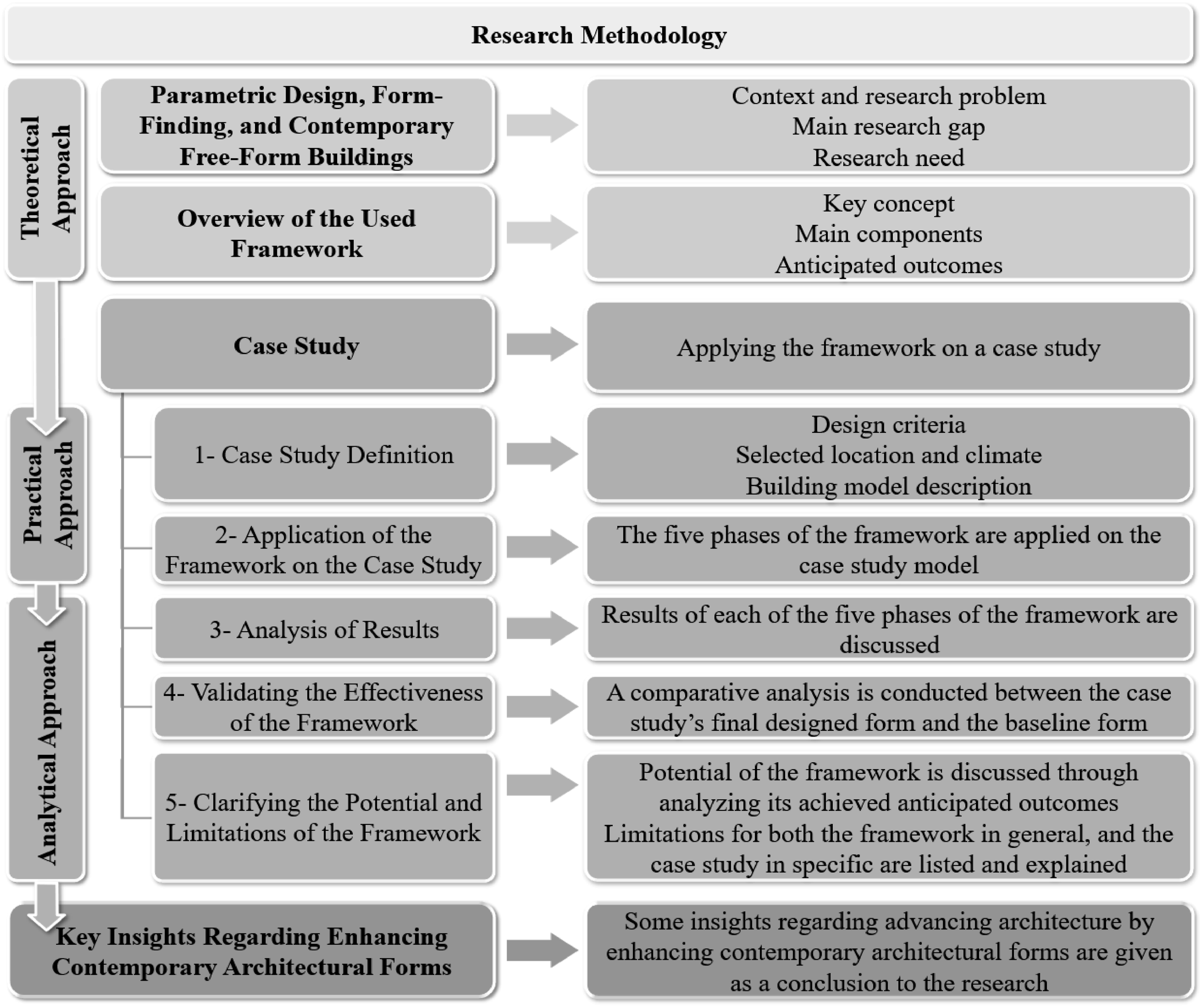
The research first adopts a practical approach. In the first step, the case study is clearly defined by listing its design criteria, selected location and climate, and building model description. It is important to note that the case study in this research is hypothetical as this allows for a focused exploration of the framework’s potential without the constraints and complexities of an actual real-world project. In the second step, the five phases of the framework are applied to the case study building model. This application involves the use of the parametric tool GH, along with some relevant GH plug-ins, namely Ladybug, Wallacei, Kangaroo, Human UI, and OpenNest.
Next, the research adopts an analytical approach. In the third step, the results of each of the five phases of the framework are further discussed in detail. In the fourth step, a comparative analysis is conducted to validate the framework’s effectiveness, comparing the results of the final designed form with that of the baseline form. The comparison included the three design objectives defined in the framework, namely energy performance, digital fabrication, and aesthetics. In the fifth step, the potential of the framework is discussed through analyzing its achieved anticipated outcomes. Additionally, the limitations of the framework in general and the case study in particular are identified and explained.
Finally, the research concludes with some key insights into advancing architecture by enhancing contemporary architectural forms through using comprehensive multi-objective optimization in the form-finding of these forms.
Case study
This section represents the case study description and the application of the used framework on this case study. A hypothetical design scenario i.e. representative of real-world applications was created for the case study building model based on some criteria relevant to the study’s objectives. These criteria include that: • The building should be a complex free-form geometry that represents most of the parametric designs we see nowadays. • It should be located in a challenging climate that demands an energy performance optimization. • It should have a flexible function (e.g. multi-use building) to avoid considering the strict design requirements for some types of buildings which would shift the case study from its main purpose. • The skin of the building model can be tessellated into panels in order to provide flexibility and freedom in their fabrication technique.
Case study location and climate
The location selected for the case study is The New Administrative Capital City in Cairo, Egypt. The city is under construction of its first phase, planned to be a mixture of different architectural styles, 31 which makes it very promising for all types of new projects. Therefore, it is a good place to seek architectural innovation. Streets of the New Capital are straight and wide with widths varied from 40 to 150 m. 32 Most of the designed towers in the area vary in height from about 55 to about 190 m (excluding the iconic towers). 33
The New Capital generally has a challenging desert climate, which is classified in the “BWh” category according to Köppen-Geiger climate classification. 34 The chosen weather file is uploaded in. 35 Monitoring station is located at Cairo Airport.
Case study model description
The building is designed to be a free-form, multi-use, multi-storey building with an area of about 1200 square meters and a total height of 117 m. The subtractive fabrication technique will be used for the final fabrication of the building’s panels to match the limitations of the used framework. The surrounding buildings vary in height between 50 and 150 m, while the streets are 40 m in width.
Application of the framework
The framework was applied on the case study model. A script that represents each of the five phases of the framework was written on GH canvas using all the necessary tools and plug-ins, as shown in Figure 3. It is obvious from the figure that all the phases of the framework inform and complete each other from the Form Generation to the Digital Fabrication of the Prototype phase. All the performed steps and the resulted outputs in each of the five phases are shown in detail in the following sections. Script of the whole framework applied on the case study model. Source: Authors.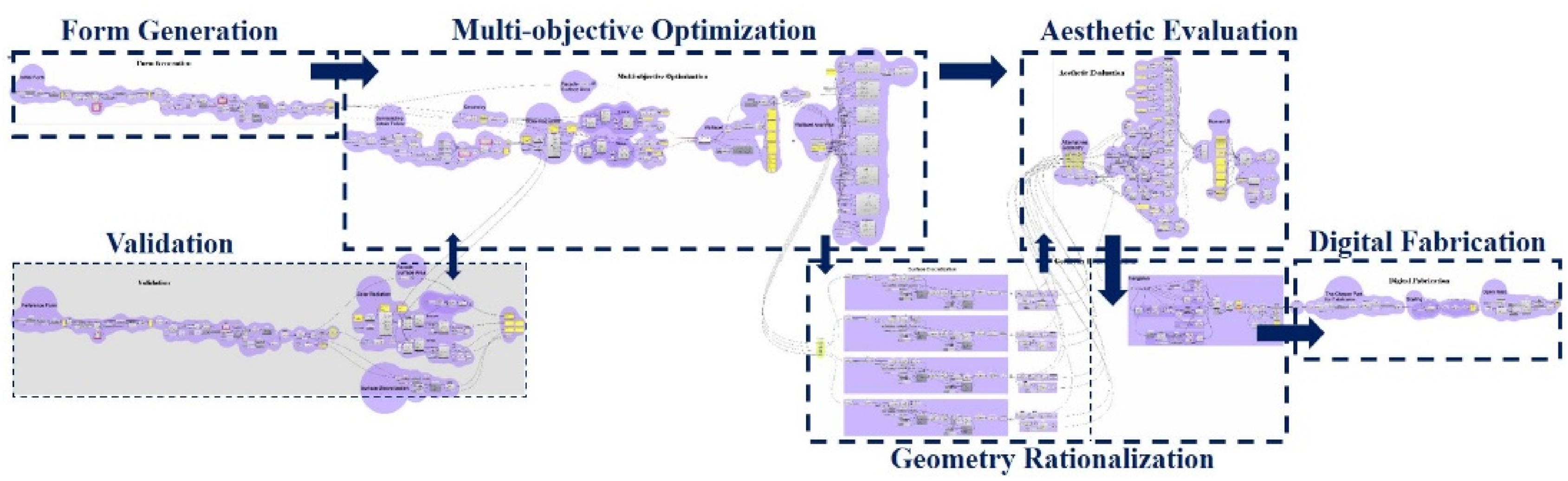
Phase one – Form generation
This phase was done through the four following steps: • Setting the design approach
In general, there are various approaches that inspire and control the initial shape of the form such as: nature, mathematical and physical principles, geometry, spatial and organizational principles, context, performance, material properties, structural logic, and fabrication. 36 The starting point here is no longer a geometry derived solely from an architect’s intent, but from a series of objectives. Choosing between these approaches depends on the nature of the specific design case and its main objectives. Therefore, three main approaches were chosen for the starting form in this case study: geometry, fabrication, and structural logic.
In response to these constraints, a geometry which satisfies the following rationalization goals: planarity of panels, torsion-free nodes, and face offsets (conical meshes) was targeted since the beginning of form generation. This was done by searching for a parametric modeling method which automatically generates only buildable structures of that certain type. Therefore, Monge’s surfaces were a perfect match. Monge’s surfaces define a large family of forms which can be easily and naturally meshed by planar quadrilateral conical meshes.
38
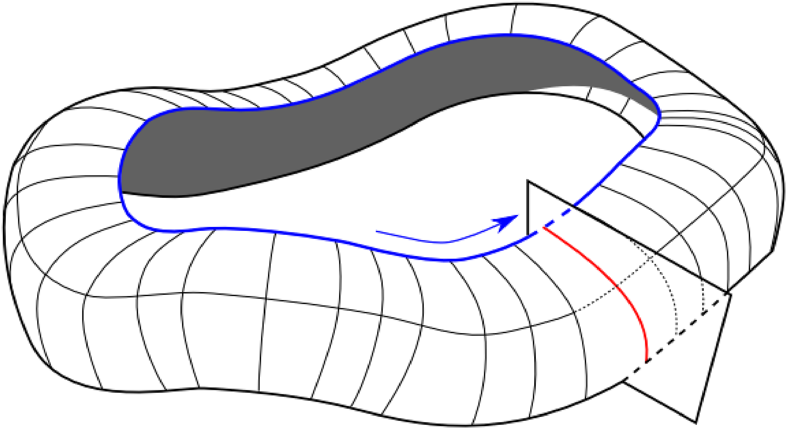
They are generated by sweeping of a planar curve, called generatrix curve along another planar curve, called rail curve. The generatix curve must be in the normal plane of the rail curve, as illustrated in Figure 4. Shape generation of Monge’s surface: generatrix curve (red) and rail curve (blue) Source:
38
.
The usage of Monges’s surface to generate planar quadrilateral panels has a great effect on the rationality of the design and its structure. In addition, the special features of conical meshes (having torsion-free nodes and face offsets) make them very compatible with double layer structures. • Defining constraints
The design constraints in this case study are mainly geometry constraints. This is due to that neither the function nor the site has any specific defined constraints. These geometric constraints are represented in two points: - Both two curves forming the initial form (generatrix curve, and rail curve) must be planar. - The generatix curve must be in the normal plane of the rail curve. • Geometric description of the design using parameters
The form starts with a circle geometry with a radius of 20 m. Then, this circle is divided by an angle of 30° into 12 equal parts. Half of these points are allowed to move within a range of [-7:5] meters away from the center of the circle. The curve joining these points at their final positions is considered as the rail curve. In addition, there is a line perpendicular to the rail curve. This line is divided into three equal parts. Division points are allowed to move within a range of [-3:3] meters in the direction of the x-axis. The curve joining these points at their final positions is considered as the generatix curve. The rail curve, the generatix curve, and the dynamic points are shown in Figure 5. The rail curve (blue), the generatix curve (red), and the dynamic points (green). Source: Authors.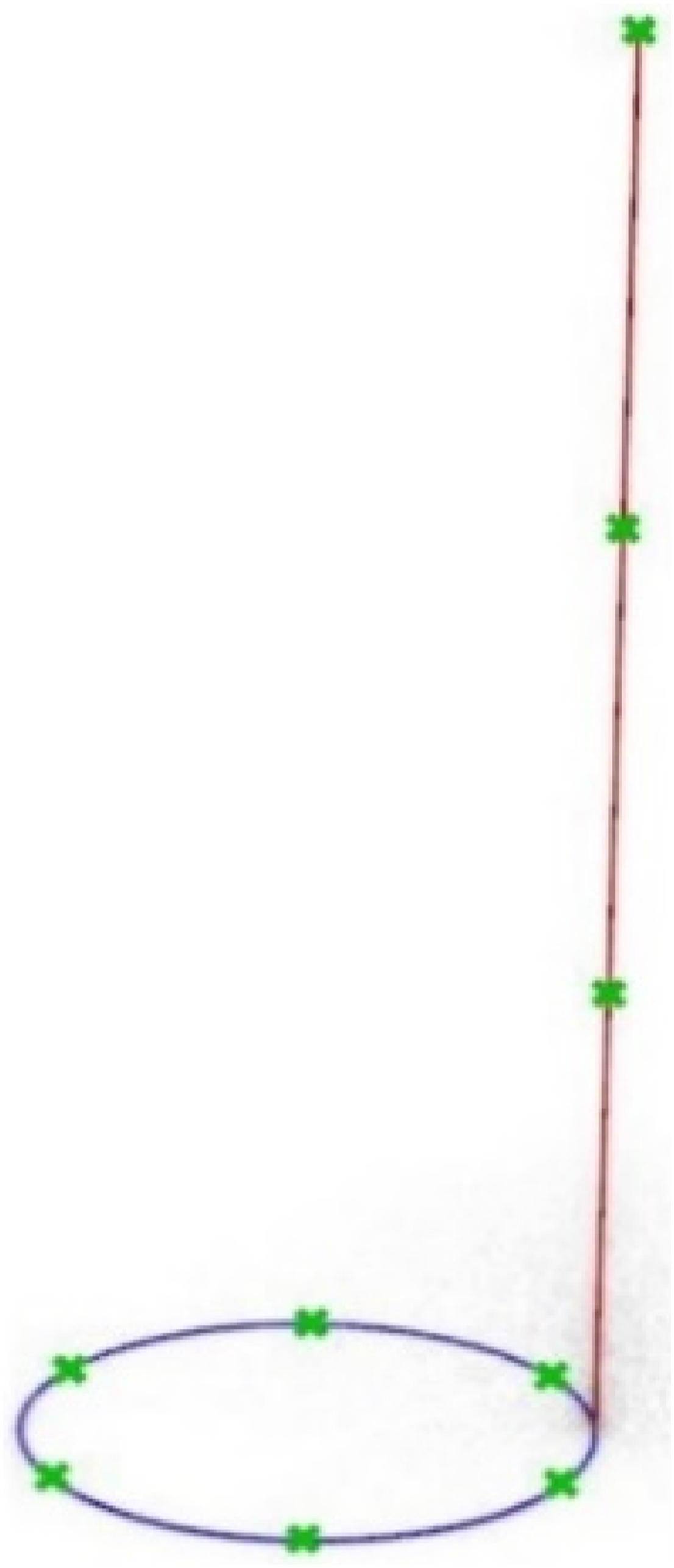
The static parameters in this case are the radius of the circle, the height of the building, and the number of division points for each of the rail and generatix curves. While the dynamic parameters which act as genes later in the Genetic Algorithm optimization are represented in some points on the rail curve and generatix curve that can move in specified directions within the specified ranges. • Forming relations between the parameters
A script consisting of 85 components, which connect all the steps and parameters contributing to generating the initial form, was written on the GH canvas.
The result of this phase is an initial design (a parametric model representing the initial form).
Phase two – multi-objective optimization
This phase was done through the three following steps: • Setting the main optimization objectives
As mentioned before, the main optimization objectives in the framework address both energy performance and digital fabrication. For the energy performance, according to the review conducted in,
29
there appeared to be a strong relation between solar radiation as an energy performance objective and buildings’ forms. Thereby, the underlying principle for optimizing energy performance in early form-finding usually remains the same for most cases, maximizing the amount of incident solar radiation in winter and minimizing it in summer. While for the fabrication objectives, the surface area of the façade being connected to the amount of used materials and number of used panels, was taken as an indicator to the fabrication feasibility. Thus, the optimization/fitness objectives (FOs) of the case study are listed as follows: (1) Minimizing the surface area of the façade (FO.1). (2) Minimizing incident solar radiation in summer (FO.2). (3) Maximizing incident solar radiation in winter (FO.3).
The solar radiation analysis was done by Ladybug using specified analysis periods, from the beginning of June until the end of August for the summer solar radiation analysis and optimization, and from the beginning of December until the end of February for the winter solar radiation analysis and optimization. Considering these months as the peak of each season in the case study location.
• Running the Genetic Algorithm
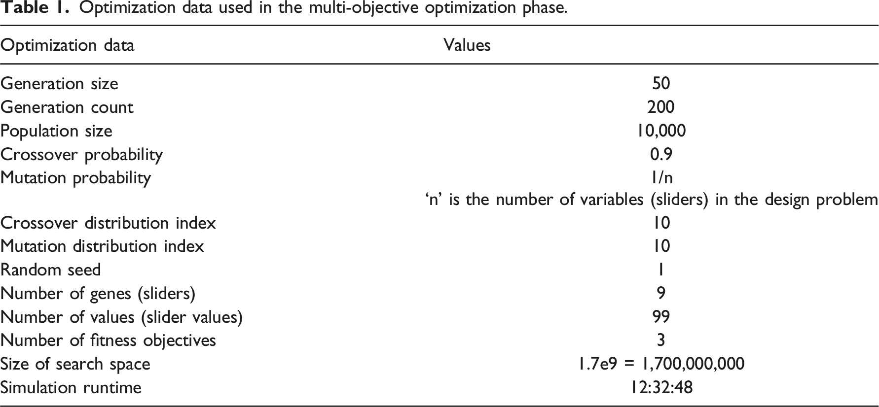
Optimization data used in the multi-objective optimization phase.
• Filtering the final Pareto front solutions
The optimization process generated a population of 10,000 individuals. The individuals of the population are named by the number of the generation and the number of the individual in that generation. Each generated individual can be analyzed using the parallel coordinate plot (PCP). We first examined the whole set of Pareto front solutions, which were 1206 solutions out of the 10,000 solutions. Then, we started to filter these solutions to come up with the solutions that give the best trade-off between the three FOs.
Unsupervised machine learning selection method, which exists within Wallacei was used. The Pareto front solutions of the entire population were clustered into 10 clusters (Cs) by using the primary clustering algorithm, K-means clustering. K-means clustering is a fast method to quickly group individuals by the predefined number of Cs based on their similar performances.
39
Figure 6 shows the clustered solutions displayed on the 3D objective space and the PCP, the solution highlighted in a bold, dash line is the C center. The 10 clusters on the parallel coordinate plot and the 3D objective space. Source: Authors.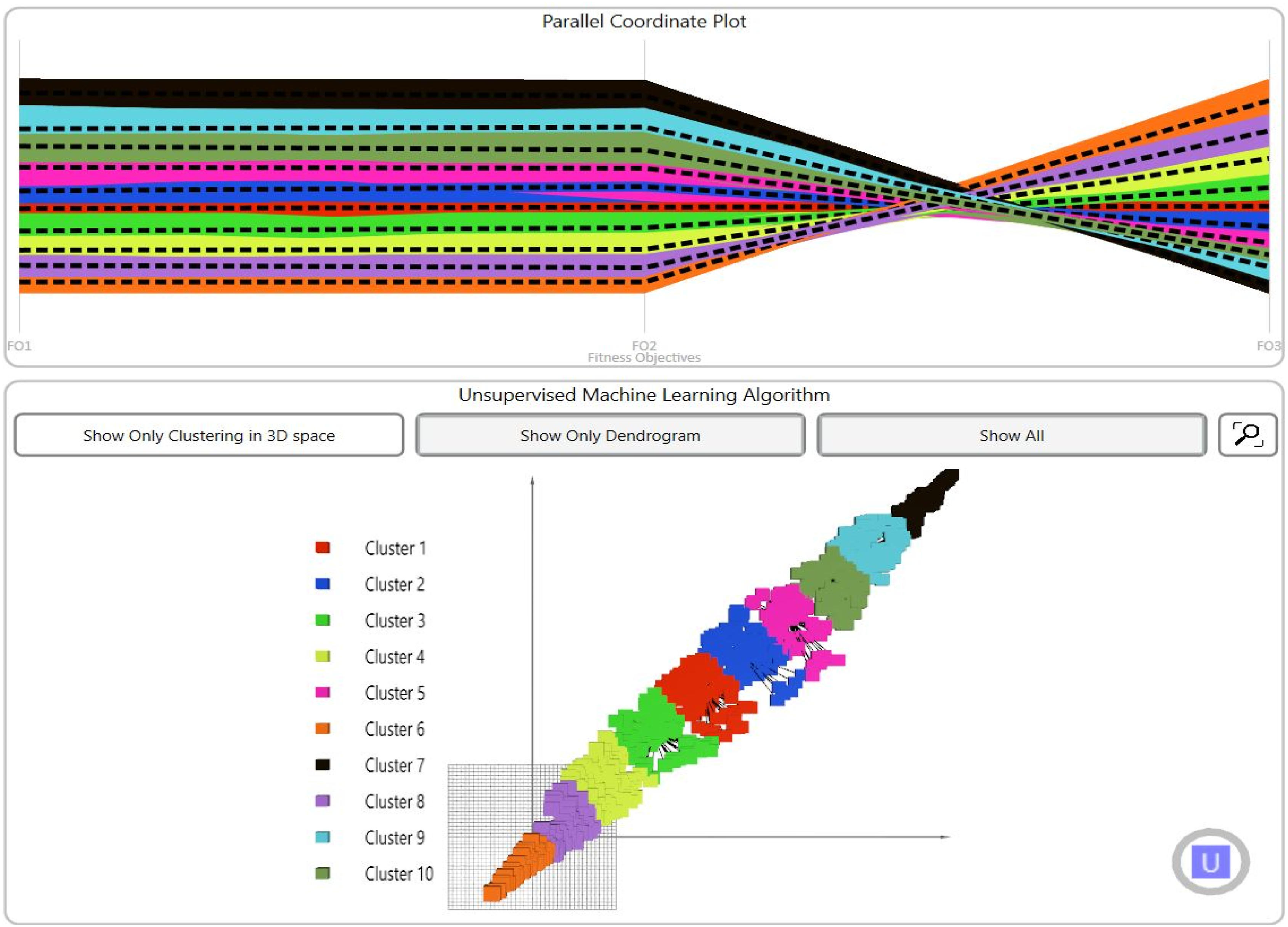
FOs of the baseline form.
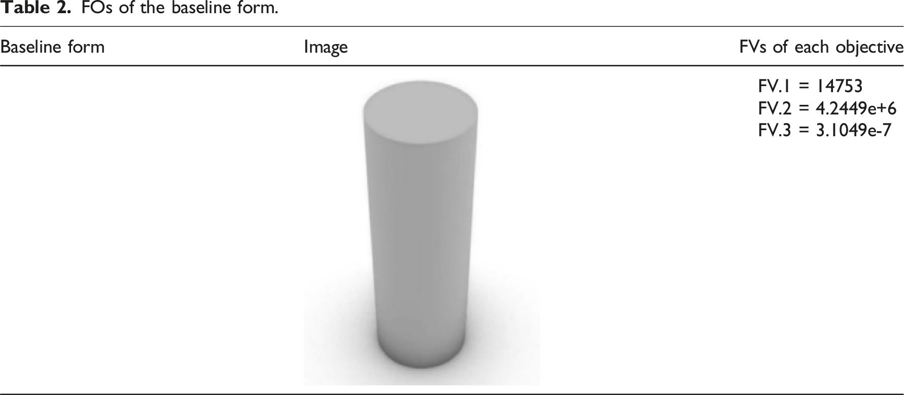
Comparing the extracted FVs of each individual from the 10 C centers with the FVs of the baseline form, we can see that none of the Cs did satisfy all of the three FO except for C2, which gave satisfying results in all the FV of the three FO comparing to the baseline form. C1, C3, C4, C6 and C8 were good in both FV.1 and FV.2, but they were not good in FV.3. While C5, C7, C9, and C10 were good in FV.3, but they were not good in both FV.1 and FV.2. The best values for both FV.1 and FV.2 were found in C6, which in turn gave the worst values in FV.3. Also, the best values in FV.3 were found in C7, which in turn gave the worst values in both FV.1 and FV.2. The main reason for these results is the presence of conflicting objectives. Therefore, C2 was chosen to be further filtered for the final solutions as it is the only C which somehow managed to balance the three FOs.
The final filtered set of Pareto front solutions.
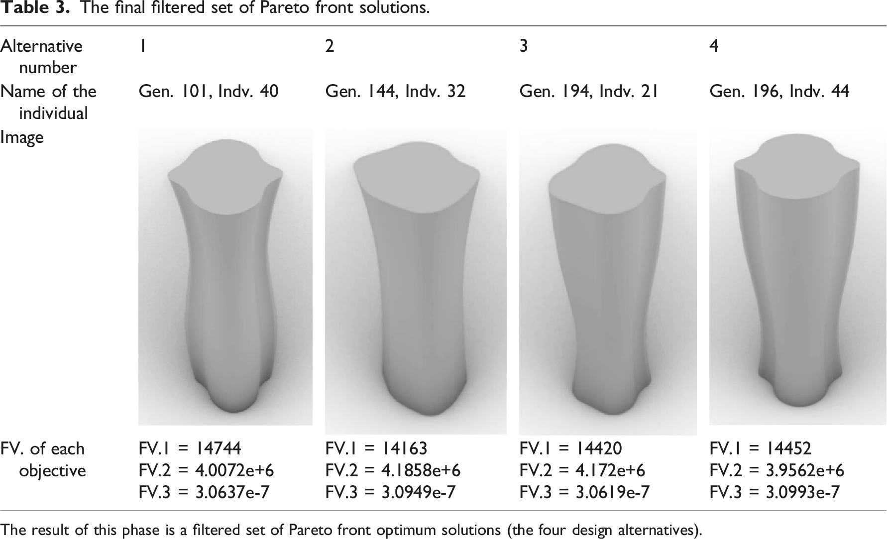
The result of this phase is a filtered set of Pareto front optimum solutions (the four design alternatives).
Phase three – Aesthetic evaluation
This phase was done through one step: • Evaluating the chosen Pareto front solutions in terms of aesthetics
A considerable number of the building’s users were involved in choosing a final aesthetically appealing solution from the four final design alternatives. We only involved users with an architectural background to be able to understand and translate their aesthetic preferences. The number of users involved was 208. This number is based on the Web site, 40 which calculates the number of sample size needed for a given population.
A simple user interface was designed using Human UI, with an embedded online questionnaire done by Google forms. This user interface is shown in Figure 7. Involved users were mainly asked to look at the provided design alternatives, with the ability to navigate around them, zoom in and out. Then, fill in the online questionnaire form. The questionnaire included two sections (see Appendix B). In the first section, the user only indicates which alternative is the most aesthetically appealing from their opinion. The other section includes eight questions. Four of them focus on knowing more about users’ aesthetic preferences in general, while the other four focus on knowing what their decision for the alternative was based on. The designed user interface for aesthetic evaluation. Source: Authors.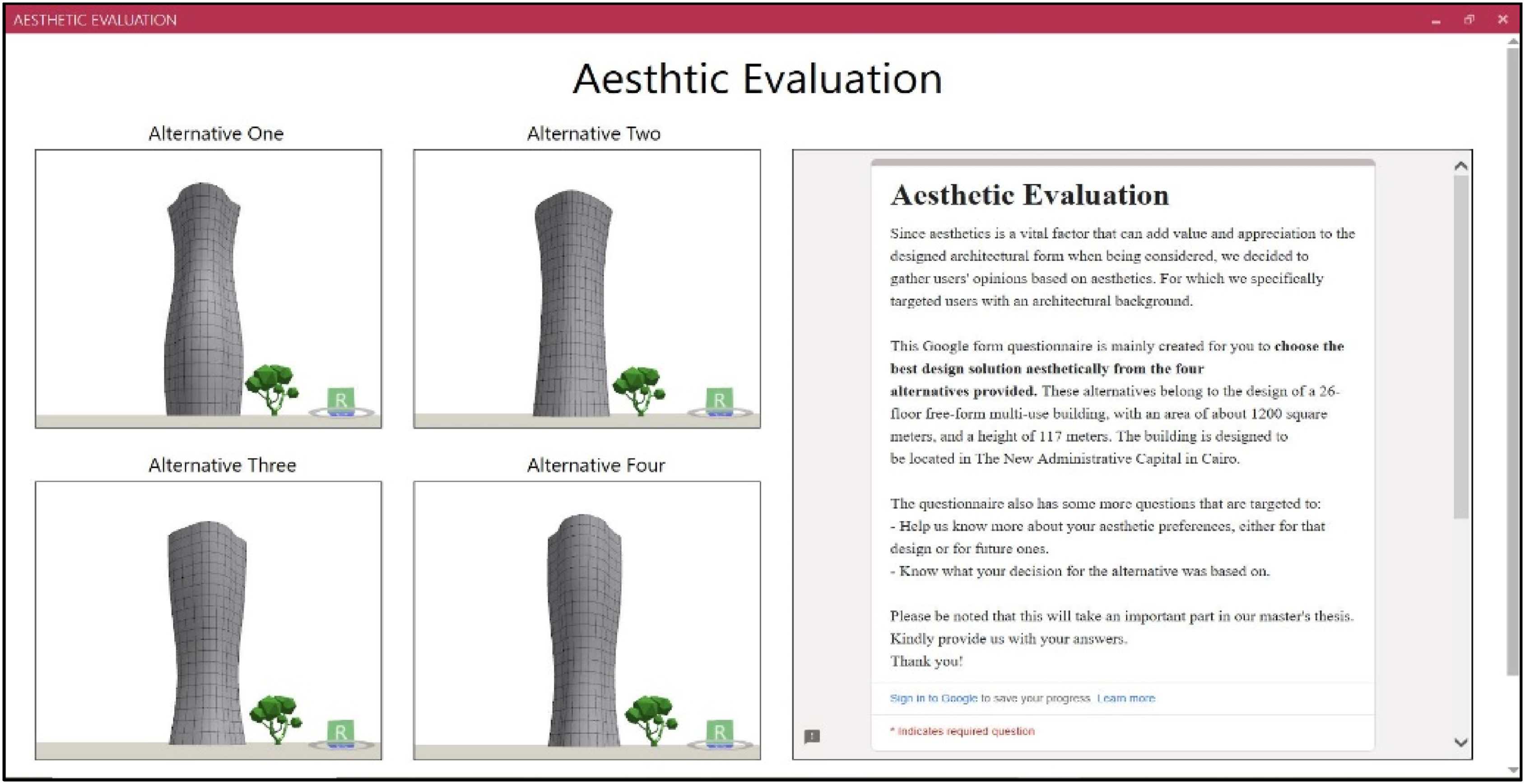
Results of the questionnaire were collected and analyzed. Regarding the most chosen alternative, we found that alternative one was chosen by 57 users (27.4%), alternative two was chosen by 37 users (17.8%), alternative three was chosen by 88 users (42.3%), and alternative four was chosen by 26 users (12.5%). This indicates that alternative three was the most chosen alternative as shown in the chart represented in Figure 8. Therefore, we proceeded with that alternative to the next phase of the framework. All the other data collected from the questionnaire will be discussed later in the discussion section of the paper. Chart of the chosen most aesthetically pleasing alternatives. Source: Authors.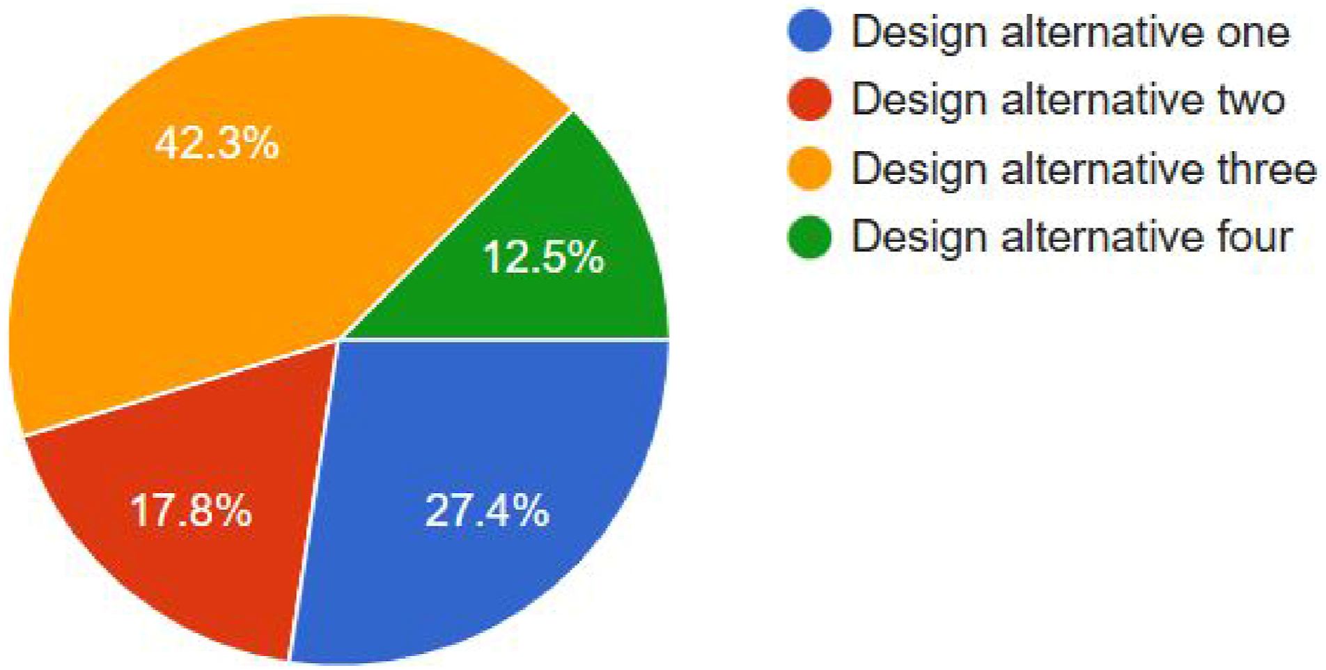
The result of this phase is a final chosen solution (alternative three).
Phase four – Geometry rationalization
The two following steps were applied in that phase: • Surface discretization of the free-form
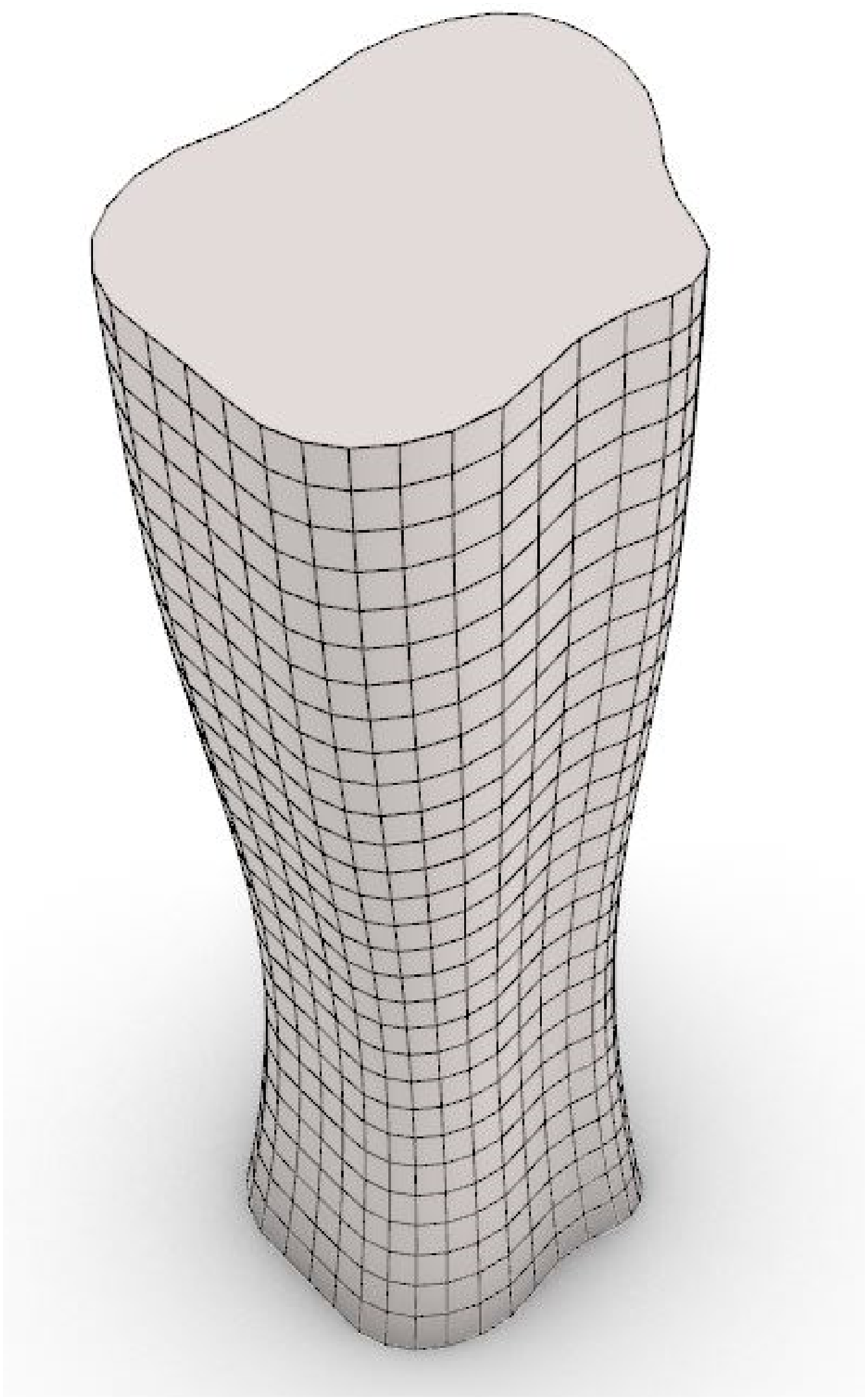
The surface of the final free-form design alternative was discretized into quadrilateral panels. These quadrilateral panels were created by using the principal curvature lines of the surface as guides. The number of resulting panels was 1102. Discretized surface of the final form is shown in Figure 9. • Geometry adaptation for the panels of the free-form Discretized surface of the final form. Source: Authors.
For the prototype digital fabrication performed later, the standard dimensions of the used material (MDF) sheets is 0.9 m × 2.4 m, while the dimension limit that the used machinery (laser cutter, type: laser engraving machine-SM 1309) can perform (working area) is 0.9 m × 1.3 m. Therefore, during the initial discretization of the form, we specified the lengths of the edges of the panels to be about 4m, so that after scaling them by scale factor 1:8 they would be convenient for the prototype fabrication with the mentioned material and machinery (they would not exceed the dimensions limit).
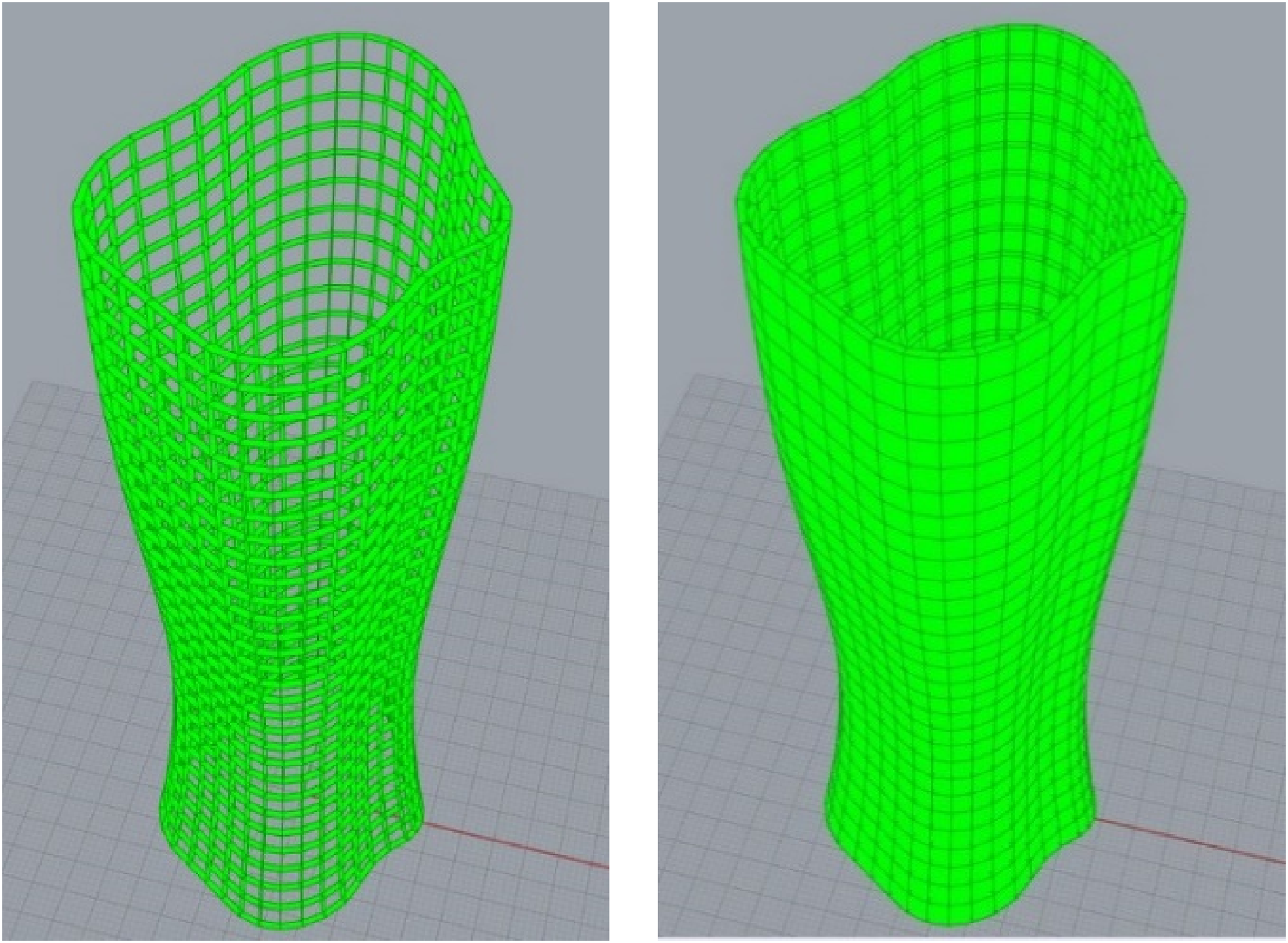
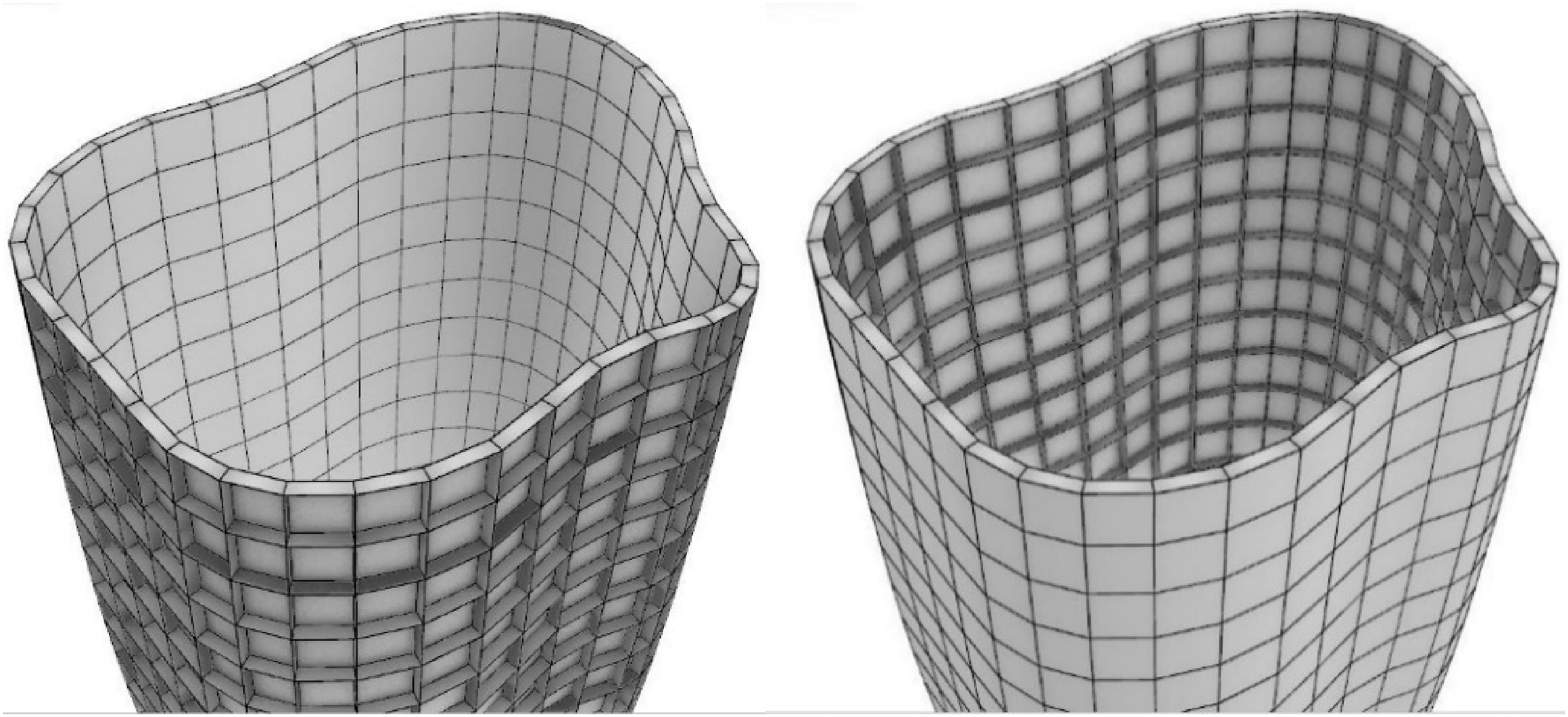
In addition, the geometry was adjusted by transforming all the panels of the free-form facade (including the double-curved panels and the single-curved panels) into flat panels in order to be applicable with the subtractive fabrication technique. Besides the planarity of panels, another rationalization goal was to transform panels into conical panels to make use of the amazing features of that type of panel (torsion-free nodes, and face offsets) in the possibility of adapting the form to be a double-layered structure at a later design stage. Kangaroo plugin was used for the panels’ transformation. According to that, we specified in the Kangaroo goals that all the panels must be planar, conical, while keeping both their lengths and inscribed angles the same in order not to deviate from the original form. After 16,520 iterations, Kangaroo’s solver converged. We ran a planarity test for the panels as a final step to ensure that all the panels are completely planar. Then, we measured the deviation of the vertices of the final mesh from that of the original mesh. We also tested the offset mesh and the generated beams (from offsetting the mesh) for both planarity and distortion. The deviation of the vertices of the final mesh from that of the original mesh ranged from 0.0001 to 0.1 m, which indicates that the resulting mesh is very close to the original one. Each of the original mesh, the generated beams, and the offset mesh were planar and free of any distortion. Visualization of these results is shown in Figure 10, 11 and 12. Planarity test for the final rationalized form before (left) and after (right) the panels’ transformation (planar panels are green). Source: Authors. Planarity test for the beams generated from offsetting the mesh (left), and the offset mesh (right) (planar panels are green). Source: Authors. The original mesh with the beams generated from offsetting the mesh, and the offset mesh with the beams generated from offsetting the mesh. Source: Authors.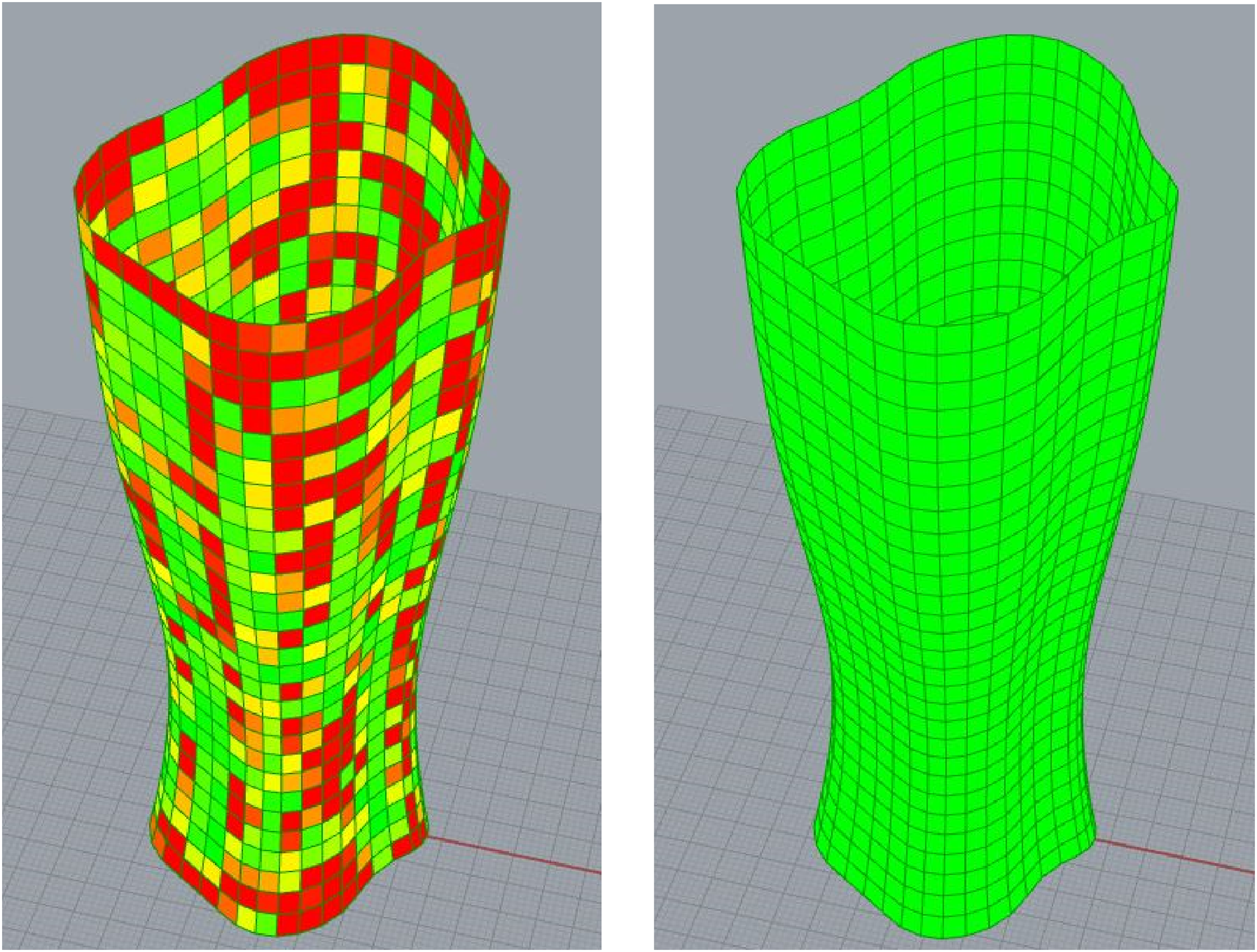
The result of this phase is a final rationalized solution (a building with a façade of planar, quadrilateral, conical panels).
Phase five – digital fabrication of a prototype
In this final phase, the two following steps were applied: • Scaling the final rationalized 3D model to the desired scale of the prototype
The final rationalized model was scaled by scale factor 1:8 for the fabrication of a prototype. • Preparing the scaled model for fabrication
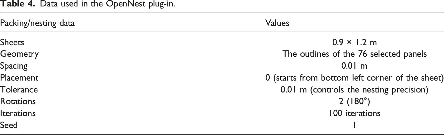
A part of the scaled model consisting of 76 panels was chosen for the prototype fabrication, as shown in Figure 13. These panels were transformed into 2D polylines and projected to the XY plane to be packed using OpenNest, where we specified a spacing of 0.01 m between the parts, and an overall tolerance of 0.01 m. The sheet size provided for OpenNest was 0.9 m × 1.2 m, which fits within the dimensional limits of the laser cutter’s working area (0.9 m × 1.3 m). Additionally, by using MDF material sheets with standard dimensions of 0.9 m × 2.4 m, each sheet can be divided into two equal parts (2 × 0.9 m × 1.2 m), maximizing material consumption. Data used in the OpenNest plugin are shown in Table 4. The chosen part of the model for the prototype fabrication (highlighted in green). Source: Authors. Data used in the OpenNest plug-in.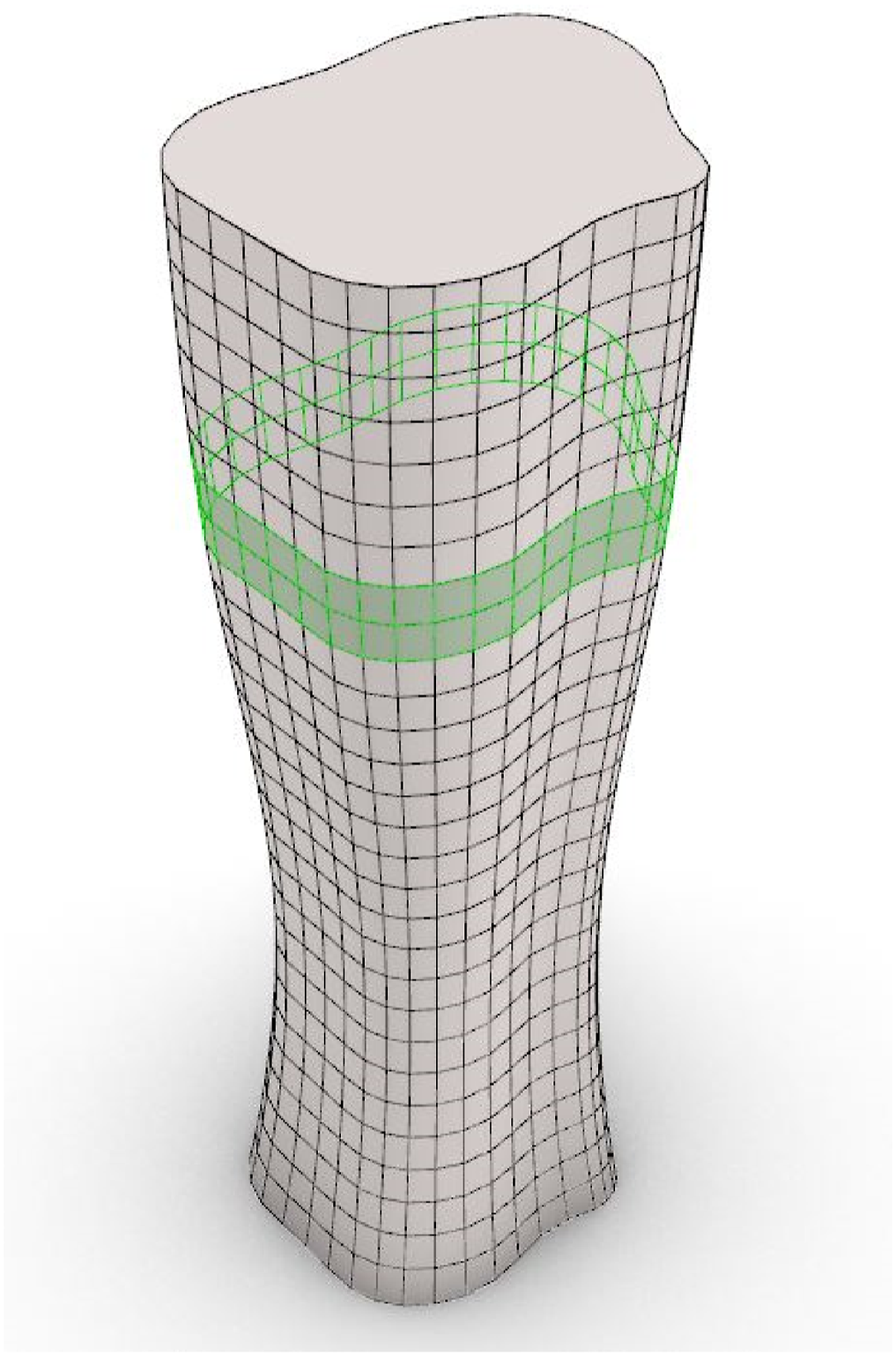
The plug-in performed the specified number of iterations (100), trying to find the best distribution for the panels (the minimum sheets consumption). Finally, the total number of sheets was 27, which is 13 and half of the actual MDF material sheets, with the 76 panels packed in them. All panels were numbered to ease their collection and assembly after fabrication. The final packed panels, with their corresponding numbers, are shown in Figure 14. The final packed panels (bottom) with their corresponding numbers on the model (top). Source: Authors.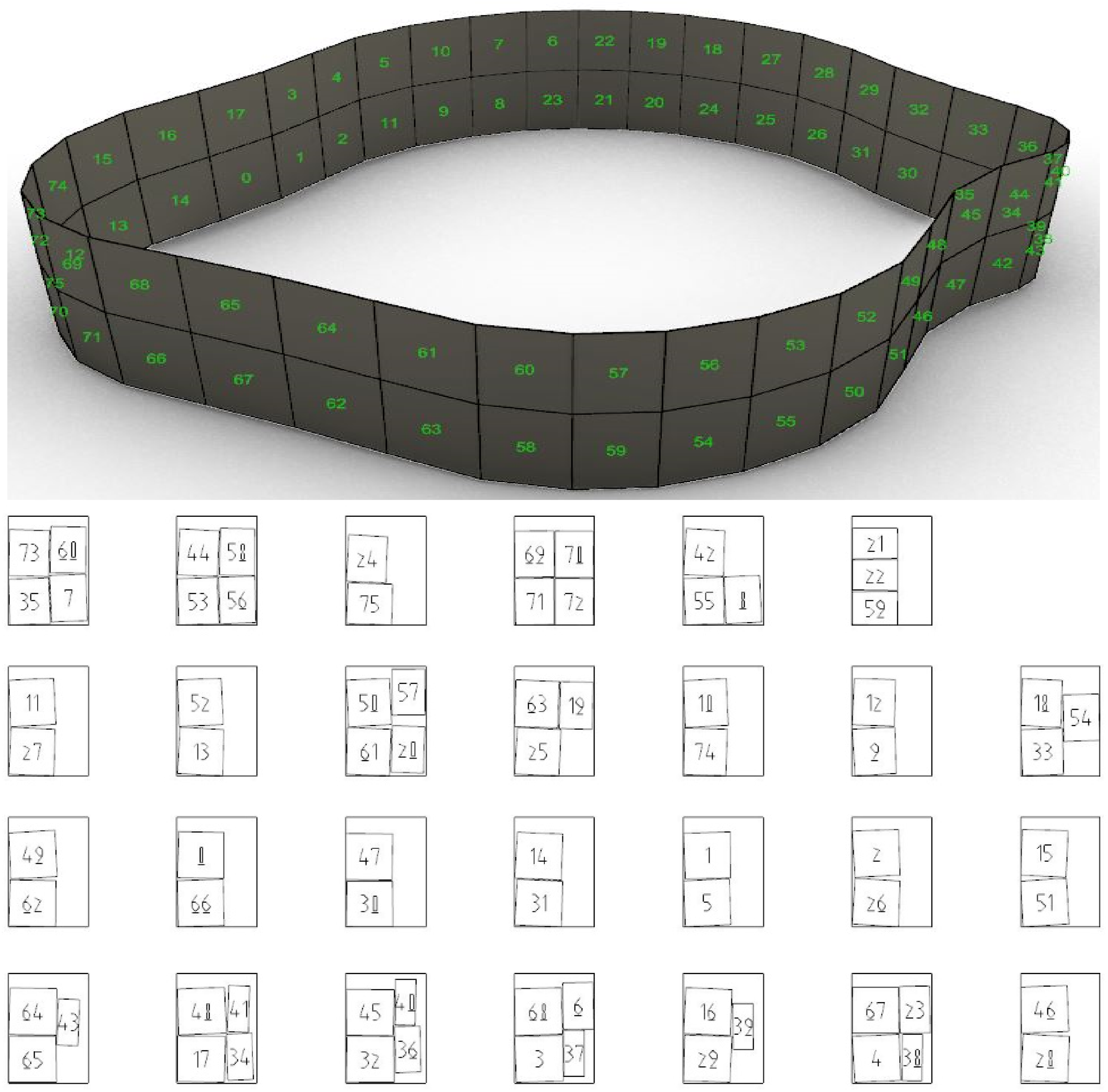
Once the panels are prepared for fabrication, the file is saved in DXF format and sent to the laser cutter’s system. The laser cutter then processes the file, producing panels precisely as specified. Following this, the panels are manually assembled to form the targeted part of the prototype. If connections between panels require openings, engravings, or other additional details, these should be added prior to the packing stage. Also, it is important to note that when both actions of cutting and engraving are needed, the packed geometry should be organized into separate layers to clearly indicate which elements are designated for cutting and which for engraving.
The result of this phase is a fabricated prototype of the final, rationalized design.
Discussion
Procedures and results of each phase of the framework are further analyzed and discussed in this section.
Phase one – Form generation
Although the approach to the initial form was based on geometry, fabrication, and structural logic. The architect still had a huge impact on the shape of the initial form. The geometry parameters defined by the architect in the phase greatly affect the shape of the produced forms. Therefore, using the same design approaches can still generate an endless variety of architectural forms depending on the geometry parameters defined by the architect in the Form Generation phase.
Phase two – Multi-objective optimization
The presence of conflicting objectives in optimization made it difficult to find highly optimized solutions for all three FOs together. Instead, we searched for solutions that have managed to balance a small progress in all of them. To better understand the behavior of the specified FOs, each of them is further analyzed throughout the whole optimization process. The analysis included the Mean Values Trendline graph, which presents the mean FV for the FO in each generation across the entire simulation, and the Diamond Fitness chart, which presents the FVs for the most fitted solution of the FO (the individual with the highest fitness rank (zero)). Each axis on the Diamond Fitness chart represents a FO. The closer the point to the center of the diamond the fitter the solution. More data and demonstrations about these graphs and charts can be found in the Wallacei Primer, found at their Web site. 41
FO.1 - Minimum façade surface area
In the Mean Value Trendline chart for FO.1 (Figure 15), we can see that the average line in the graph is going up with an angle of 6.5°. This indicates that the mean FVs are increasing (solutions are getting less fitted). This result of the graph is greatly affected by the first five generations which show very low FVs. After the first five generations, the mean fitness is constantly going up and down, which is normal for that kind of problem. However, we can see that there has been a significant reduction in the FVs for the last five generations. Mean Values Trendline graph for FO.1. Source: Authors.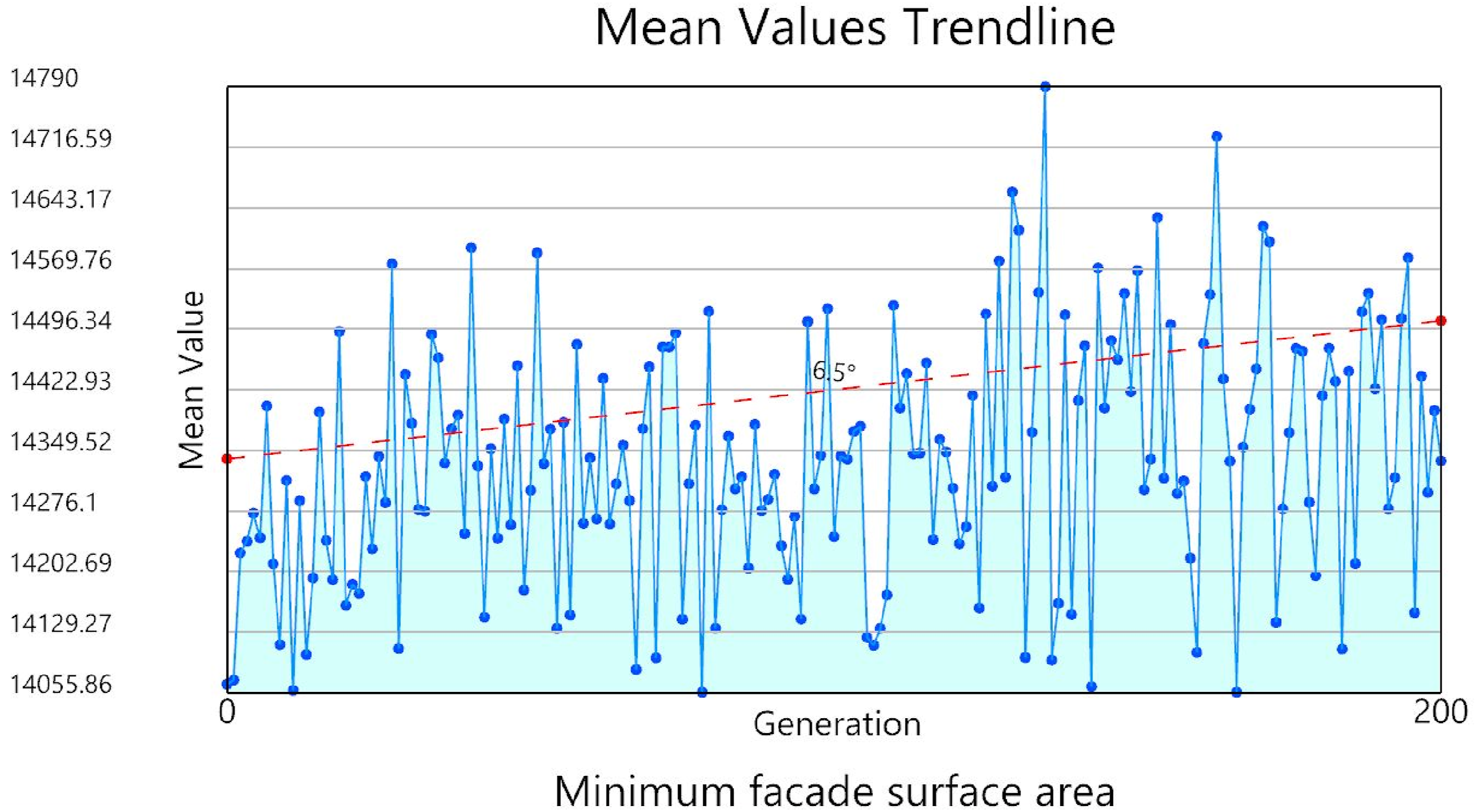
In the Diamond Fitness chart of FO.1 (Figure 16), we can see that the most fitted (highest rank) solution in minimizing the surface area of the façade is individual number 1, located in generation 195. This individual also obtains a very low fitness rank for FO.3, and a very high fitness rank in FO.2. Diamond Fitness chart of the most fitted solution for FO.1. Source: Authors.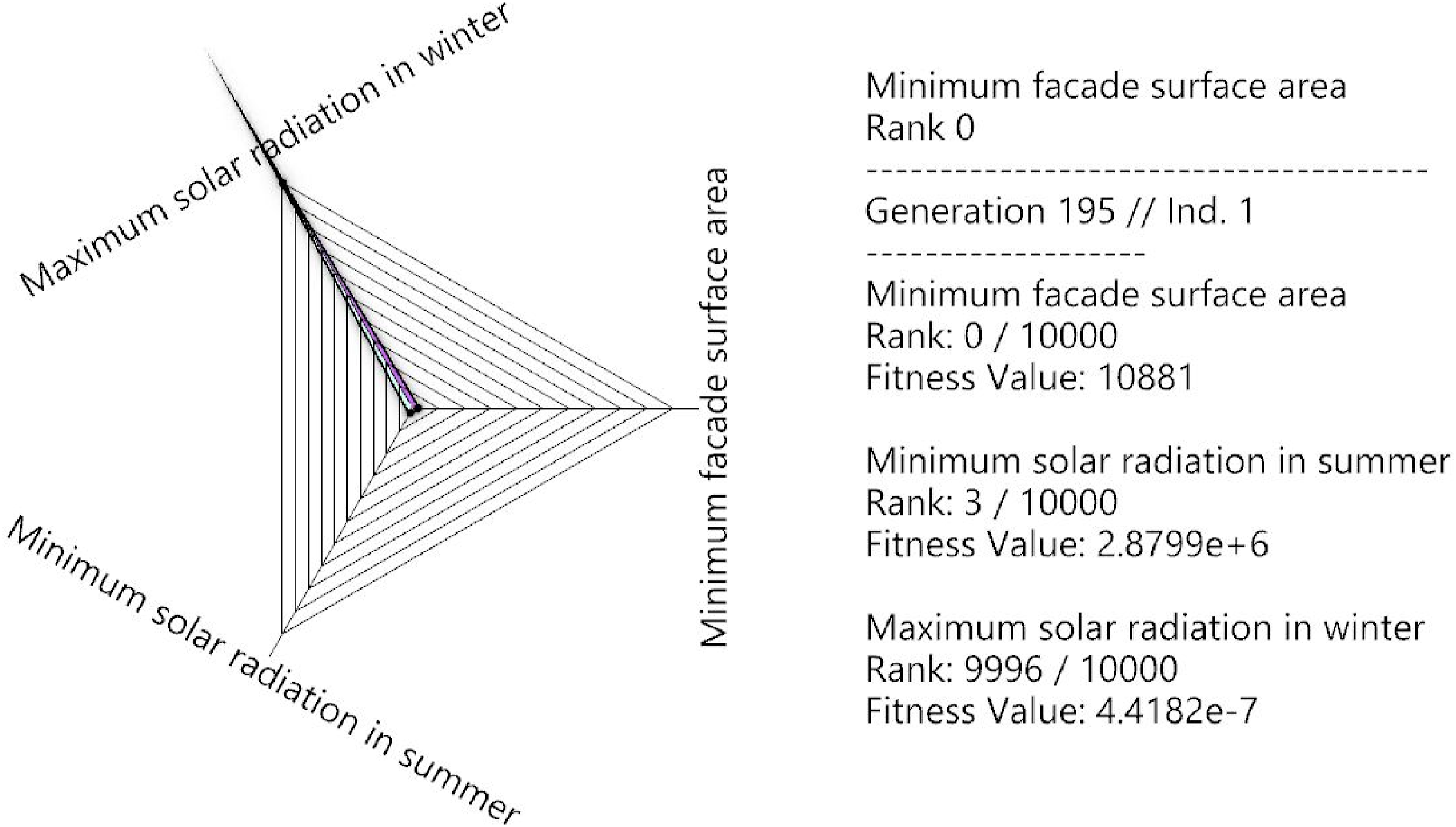
FO.2 - Minimum solar radiation in summer
In the Mean Value Trendline chart for FO.2 (Figure 17), we can see that the average line is going down with an angle of 2.39°, which indicates that the mean FVs are decreased throughout the simulation (solutions are getting more fitted). We can also see that the mean FVs have decreased dramatically in the last five generations. Mean Values Trendline graph for FO.2. Source: Authors.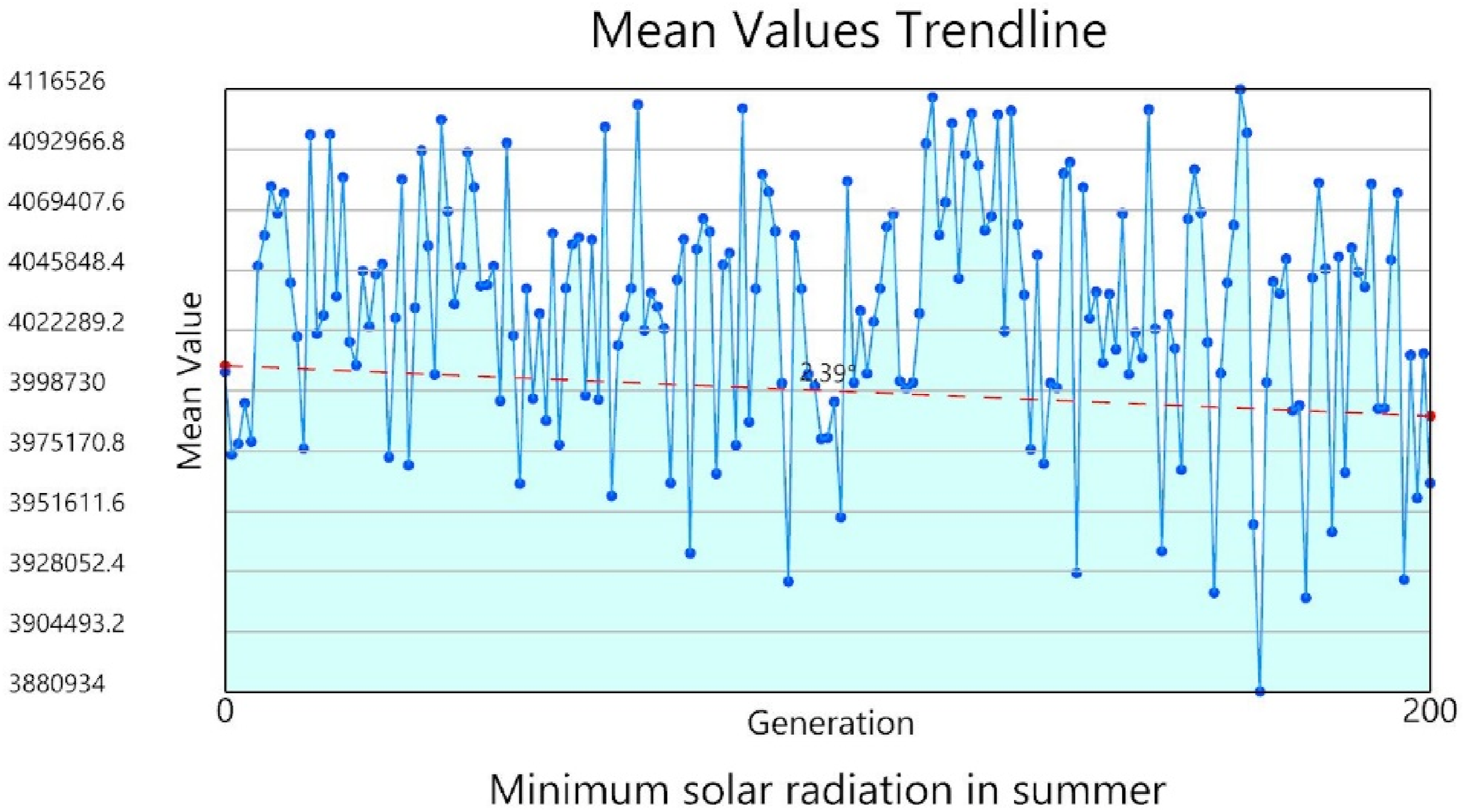
In the Diamond Fitness chart of FO.2 (Figure 18), we can see that the most fitted (highest rank) solution in minimizing solar radiation in summer is individual number 0, located in generation 193. This individual also obtains a very low fitness rank in FO.3, and a very high fitness rank in FO.1. Diamond Fitness chart of the most fitted solution for FO.2. Source: Authors.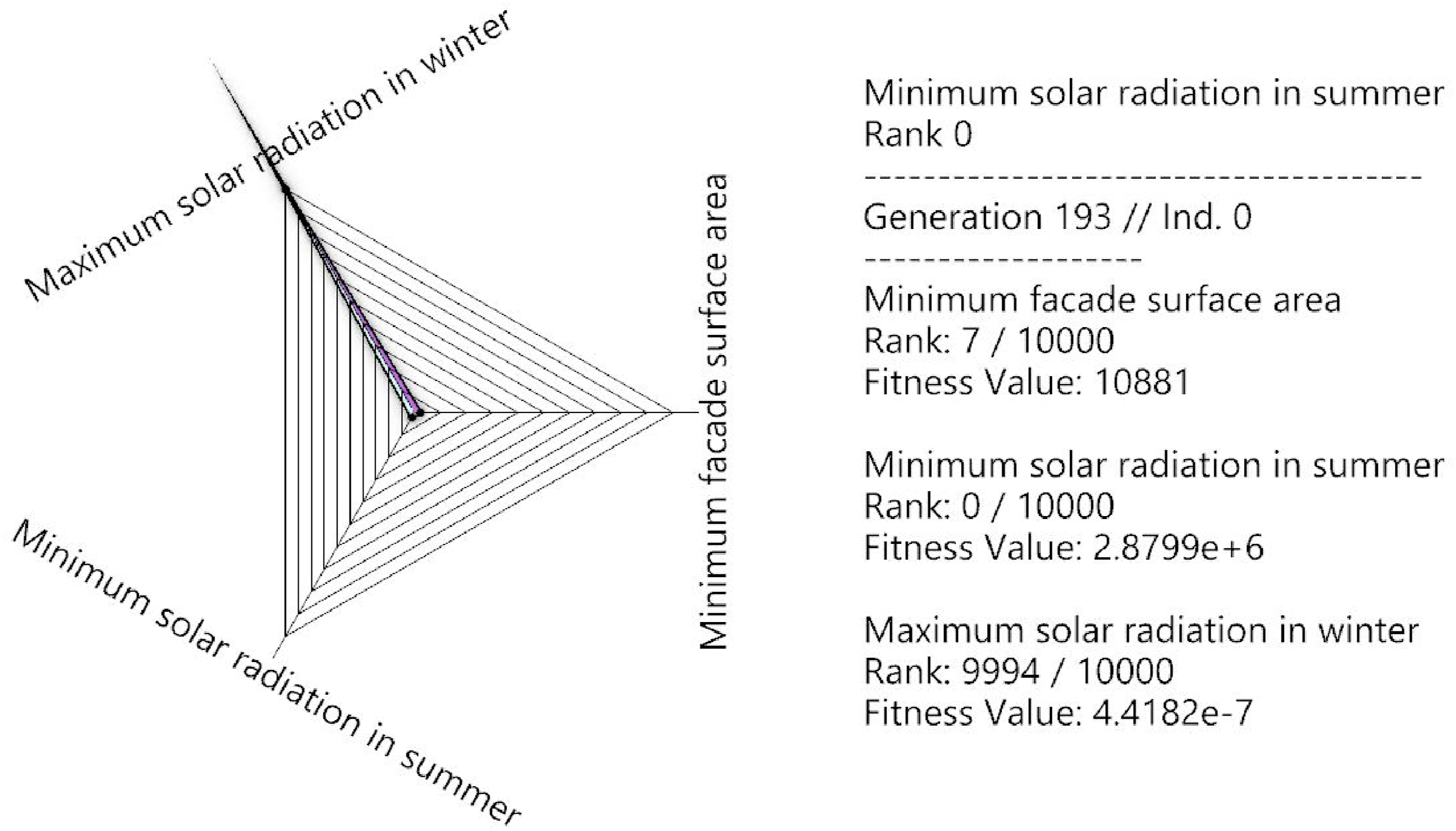
FO.3 - Maximum solar radiation in winter
In the Mean Value Trendline chart for FO.3 (Figure 19), we can see that the average line in the graph is slightly going down with an angle of 0.15°. This indicates that the mean FVs are slowly decreased throughout the simulation (solutions are slowly getting more fitted). Mean Values Trendline graph for FO.3. Source: Authors.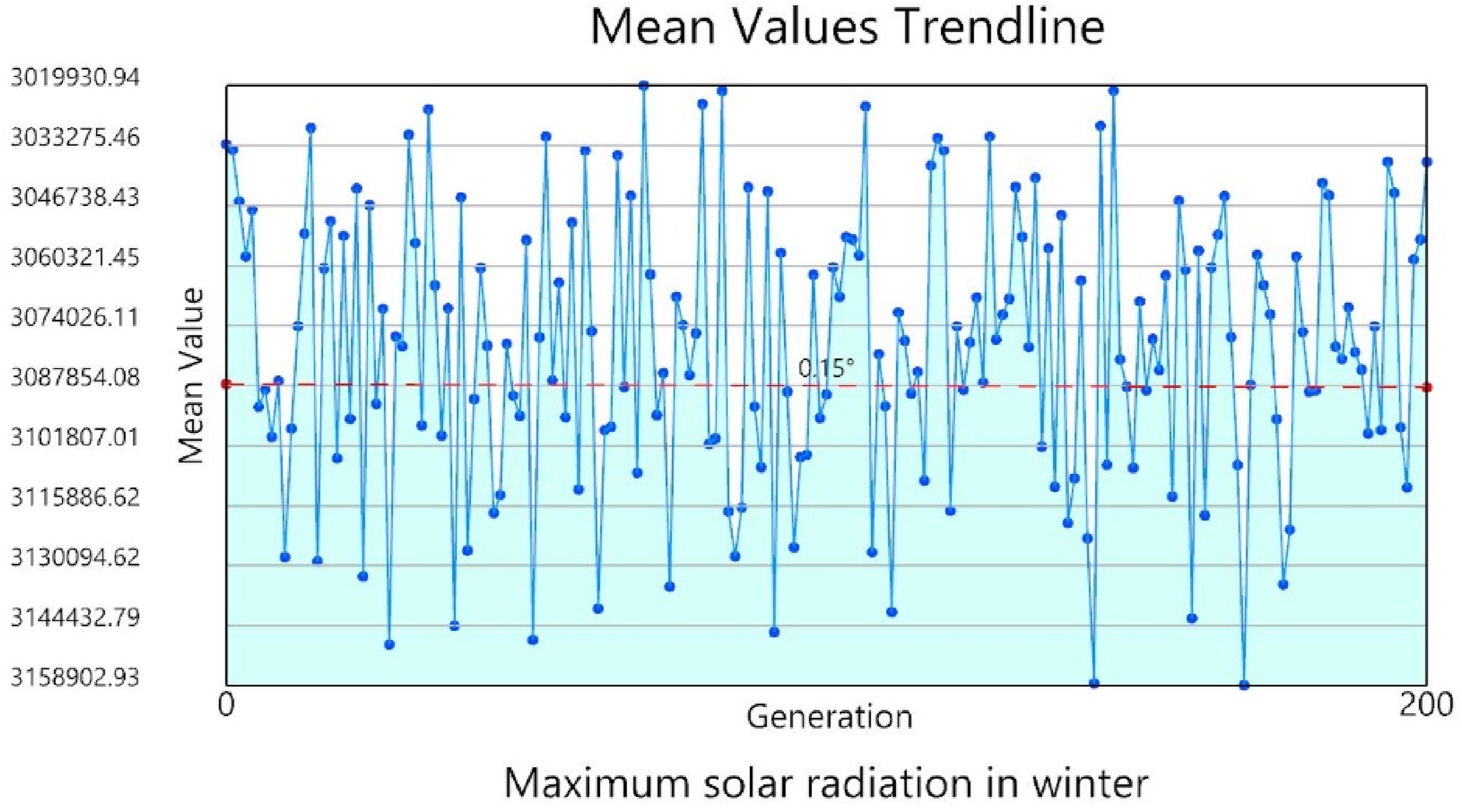
In the Diamond Fitness chart of FO.3 (Figure 20), we can see that the most fitted (highest rank) solution in maximizing solar radiation in winter is individual number 2, located in generation 134. This individual also obtains a very low fitness rank in both FO.1 and FO.2. Diamond Fitness chart of the most fitted solution for FO.3. Source: Authors.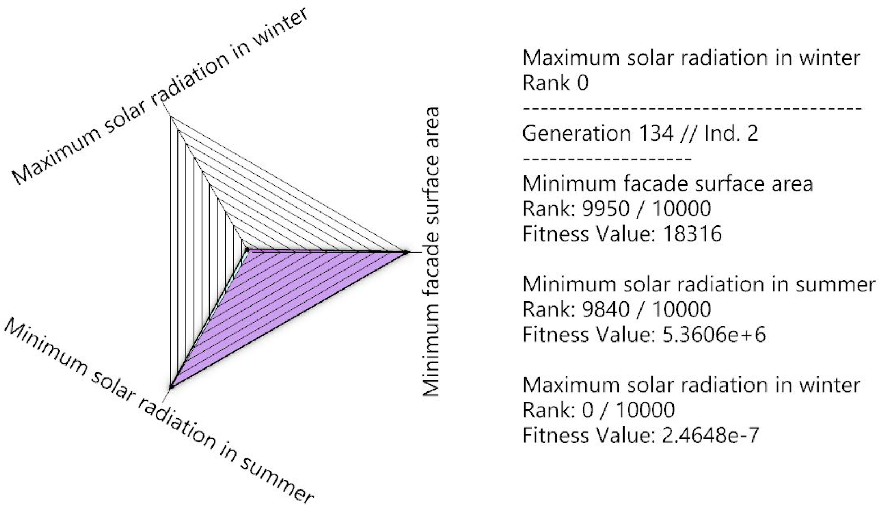
Phase three – Aesthetic evaluation
As mentioned before, the aesthetic preferences section of the questionnaire was divided into two categories; the aesthetic preferences (generally), and the aesthetic perspective of the chosen alternative (which can indicate the reason for selecting a specific alternative). From the features that affect a building’s aesthetics,
30
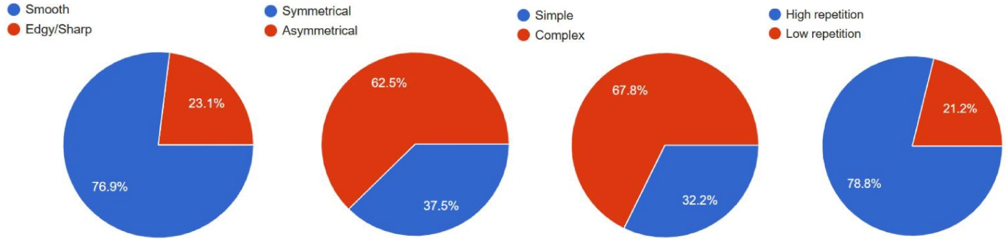
we only included the features that are relevant to the early design phases, which are building shape (configuration of surfaces and edges), symmetry (balanced and proportionate similarity in the two halves of the building), proportion (variation of dimensions of the building parts), and rhythm (repetition of panels). Answers of the different questions in both categories were collected and represented in the charts shown in Figures 21 and 22. Charts of the aesthetic preferences in general. Source: Authors. Charts of the aesthetic perspective of the chosen alternative. Source: Authors.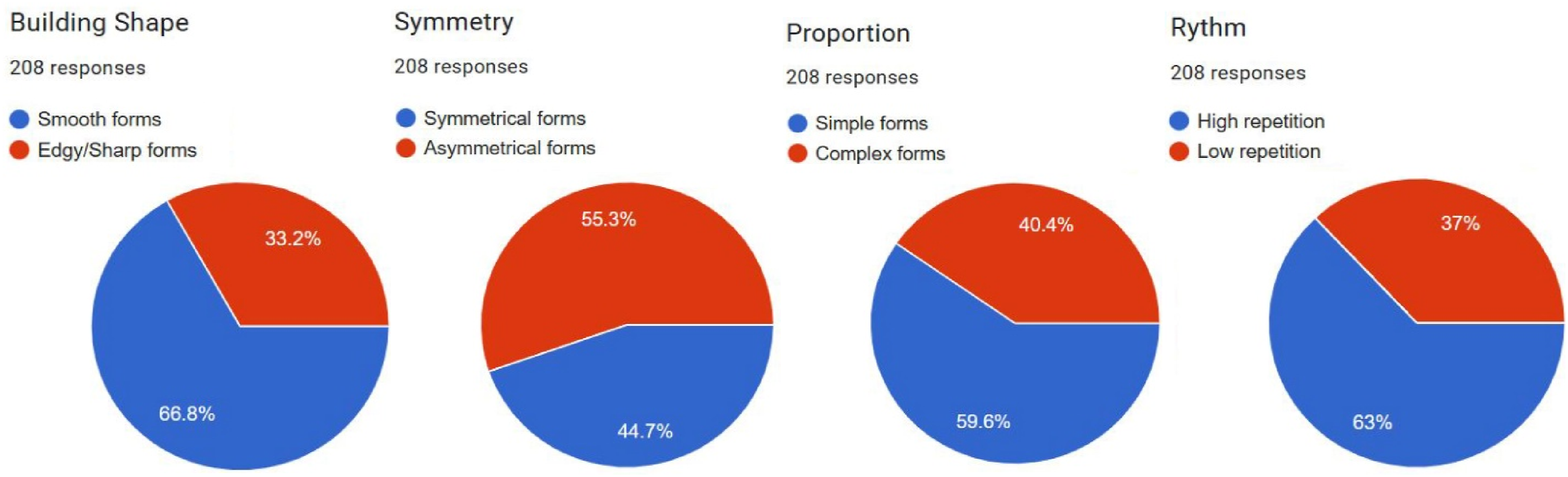
From Figure 21, we can find the following about aesthetic preferences in general: - Building shape: 139 of the users (66.8%) selected smooth forms as their preference, while 69 (33.2%) selected edgy/sharp forms. This shows that smooth forms are generally much preferred over edgy/sharp forms. - Symmetry: 93 of the users (44.7%) selected symmetrical forms as their preference, while 115 (55.3%) selected asymmetrical forms. This indicates an unusual tendency to asymmetrical forms over symmetrical ones. - Proportion: 124 of the users (59.6%) selected simple forms as their preference, while 84 (40.4%) selected complex forms. This shows that simple forms are generally preferred over complex forms. - Rhythm: 131 of the users (63%) chose high repetition as their preference, while 77 (37%) chose low repetition. This indicates a tendency to high repetition.
From Figure 22, we can find the following about the aesthetic perspective of the chosen alternative (selection reason): - Building shape: 160 of the users (76.9%) chose smooth, while 48 (23.1%) chose edgy/sharp. Although all the four alternatives can be defined as smooth forms, some users saw them with a different perspective. - Symmetry: 78 of the users (37.5%) selected symmetrical, while 130 (62.5%) selected asymmetrical. This result is proportional with the earlier selection of alternative one by 57 users and alternative four by 26 users, which both can be considered as nearly symmetrical forms. - Proportion: 67 of the users (32.2%) chose simple, while 141 (67.8%) chose complex. Although all the alternatives were originally designed to be complex forms, this result indicates that some users defined their chosen alternatives as simple forms which may be connected to the sense of symmetry in alternative one and four. - Rhythm: 164 of the users (78.8%) chose high repetition, while 44 (21.2%) chose low repetition. The difference between the dimensions of panels is not high for most of the panels, which explains the reason for this result.
In general, it is crucial to identify the specific determinants of aesthetic pleasure 42 across various designs to be able to inform and guide design decisions effectively. In this case study, the majority of users contributing to the aesthetic evaluation identified smooth, asymmetrical forms as the most aesthetically pleasing. This observation aligns with the findings of Berghman et al. in their testing for unified model of aesthetic pleasure, 43 where they stated that typicality hardly contributes to aesthetic pleasure. Given that typical architectural forms are often characterized by sharp edges and symmetry, an added aesthetic appeal was found in the smoothness and asymmetry of the designs.
Phase four – Geometry rationalization
Geometry rationalization was applied from the beginning of deciding the approach for the form generation until later after the multi-objective optimization and the aesthetic evaluation. This demonstrates that parametric co-rationalization was applied in the framework throughout the whole process as suggested by the results of the review found in. 29 The review indicated that to avoid degradation of a design during construction, introducing fabrication constraints and objectives should happen throughout the whole process of design; thereby, co-rationalization should be applied in the form-finding process.
With all the meshes of the façade being planar, the fabrication and assembly process becomes significantly more efficient and cost-effective. Planar meshes allow for straightforward cutting, fitting, and installation of panels, leading to minimizing the need for complex procedures and costly adjustments during construction, reducing the likelihood of gaps or misalignment during installation as flat surfaces are easier to align accurately, and potentially reducing material waste. Thus, contributing to both time and cost efficiency in the execution of the building.
In addition, the beams generated from offsetting the rationalized mesh in that phase, which are also completely planar, can be efficiently used for creating a supporting structure for the façade of the building in the later stages of design, facilitating the formation of a rational, double-layered structure.
Phase five – Digital fabrication of a prototype
In our case, preparing for the digital fabrication of the prototype went smoothly, with no issues encountered. However, this step is crucial for testing new designs to prevent any potential errors during the actual building fabrication, especially for more complex designs.
If any errors or fabrication challenges arise during this phase, they should be addressed and documented carefully. Early detection and resolution of issues can save both time and resources, ultimately making the actual fabrication and construction of the building more feasible. Furthermore, documentation of such issues helps in preventing similar issues in the final building fabrication, ensuring a more efficient and accurate building implementation. It also provides a reliable reference for future projects with a similar fabrication technique; thus, advancing the whole practice.
Effectiveness of the Framework
Comparison between the baseline form and the final designed form.
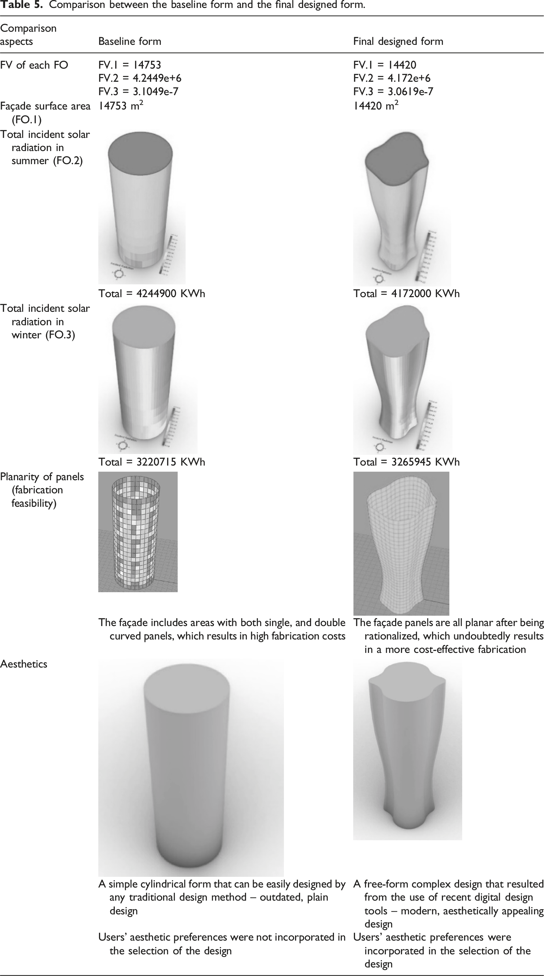
First, regarding the FVs of the three optimized FOs, the final designed form achieved better FVs than the baseline form in all of them. The façade surface area decreased by 333 square meters (2.25% compared to the baseline form), which will indeed have a good effect on reducing the materials used for fabrication, and the overall fabrication cost. The total solar radiation in the specified period in summer decreased by 72,900 KWh (1.7% compared to the baseline form), which indicates a significant long-term impact in mitigating the effects of incident solar radiation on the building’s surface during summer. While the total solar radiation in the specified period in winter increased by 45,230 KWh (1.4% compared to the baseline form), which indicates a significant long-term increase in the incident solar radiation received by the building’s surface during winter.
Second, in terms of the planarity of the façade panels, the cylindrical baseline form features areas with both single and double-curved panels, leading to higher fabrication costs due to the complexity of their fabrication. Conversely, the façade panels of the final designed form are entirely planar after being rationalized. This significantly reduces fabrication complexity, resulting in more cost-effective and efficient fabrication.
Third, in terms of aesthetics, the baseline form, which is a simple cylindrical form that can be easily designed by any traditional design method, can be described as an outdated, plain design. While the final designed form, which is a free-form complex design that obviously resulted from the use of recent digital design tools, is a modern, aesthetically appealing design. In addition, users’ aesthetic preferences were incorporated in the selection of the design as opposed to the baseline form where users did not contribute by any opinion in the design.
In conclusion, the final designed form produced from the framework application has proved to be an enhanced architectural parametric form in terms of all the specified design objectives as compared to the baseline form. This proves the effectiveness of the used framework in advancing architecture by producing enhanced architectural forms using comprehensive, multi-objective optimization in the form-finding of these forms.
Potential and limitations of the Framework
Framework potential
The framework’s application on the case study achieved each of the anticipated outcomes of the framework on the parametric form-finding process, presented earlier in the introduction section of that paper, in the following ways: • Fabrication-aware design: Incorporating fabrication between the main design approaches in the form-finding was done by Using Monge’s surface to generate the building forms to create a form that can be possibly discretized into planar quadrilateral conical meshes. Thus, the design is both easier and more cost-effective in its fabrication. • Comprehensive optimization: Through the multi-objective optimization by Wallacei, both fabrication objective (e.g., façade’s material minimization) and energy performance objectives (e.g., mitigation of incident solar radiation in summer, and maximization in winter) were considered simultaneously. This comprehensive approach broadened the scope of design optimization and ensured that the final design is both feasible and sustainable. • Aesthetically appealing form: The selection of a final design was informed by users’ aesthetic preferences through using the interactive Human UI user interface in selecting the alternative that they found to be the most aesthetically appealing between the final set of Pareto front alternatives. This approach ensured that the final design considered both practical performance and aesthetic goals. • Effective rationalization: Rationalization was introduced early in the form-finding process to govern the complexity of the design. First, the form’s façade was discretized into panels that considered the standard dimensions of the used material and the dimension limit of the used machinery. Then, the geometry of the façade was adapted to be compatible with the targeted fabrication technique and material by making all the panels planar. This approach helped in minimizing the need for substantial modifications during the upcoming later stages of the design process, significantly reducing both time and effort in adapting the design for real-world fabrication. • Error-free and cost-effective fabrication: The framework employed rapid prototyping during the early phase of form-finding, which allowed for the physical prototype to be tested, ensuring that the design could be effectively fabricated and avoiding the risk of having fabrication errors and design modifications later in the final building fabrication, ultimately saving time and costs. Additionally, the concept of panels’ packing optimization for minimum material usage has significantly reduced material waste during prototype fabrication.
The previous points imply that utilizing this framework will have a great impact on energy performance, digital fabrication, and aesthetics of the produced architectural forms. This demonstrates the potential of the framework to transform architectural practice into a more comprehensive approach, thereby enhancing the resulting architectural forms and, consequently, advancing the field of architecture.
Framework limitations
Generally, the framework has some limitations, listed in the following: • The framework utilizes the subtractive fabrication technique for producing the facade panels due to the widespread availability of its machinery and its suitability for manufacturing the facade panels, which require precise, efficient fabrication with few details. • The digital fabrication within this framework is not intended for the construction of the actual building, but rather for creating a scaled or partial prototype. This approach aligns with the nature of the framework, serving as an early-stage form-finding tool in the architectural design process. • The main criterion for choosing a design solution between the final optimized solution set in the framework is aesthetics. However, more criteria can be included in that phase according to what the specific design problem requires or what the architect decides. • The framework was created to involve the most important design objectives from the early stage of form-finding, namely energy performance, digital fabrication, and aesthetics. However, more design objectives can be added to the framework as per needed in each design scenario.
Besides, the case study presented in this paper has some additional limitations, listed in the following: • Solar radiation analysis and optimization was done within specified analysis periods, from the beginning of June until the end of August for summer, and from the beginning of December until the end of February for winter, considering these months as the peak of each season in the case study’s location. However, these periods can be adjusted according to weather conditions in any different location. • The Genetic Algorithm has been adjusted to calculate 50 individuals through 100 generations in order to have a reasonable calculation time. This number can be changed if the specific optimization problem requires that. • Despite that it is usually important to have a constant volume for the building in optimization problems, the volume of the building in our case study was not fixed. This is because Wallacei tool used in optimization does not inherently support fixed constants. Wallacei is designed to adapt and optimize various design parameters simultaneously, and enforcing constants could hinder its ability to explore and converge towards optimal solutions. However, this is not an issue in such a complex, multi-objective design scenario, where the main focus is balancing all the specified design objectives within an acceptable range of building volume and floor area. • The aesthetic evaluation questionnaire was conducted on a sample size of 208. Only users with an architectural background were chosen to be able to understand and translate their aesthetic preferences. However, this aesthetic evaluation can be performed on any other population of users. • Due to the limitation of our resources, we did not actually fabricate the prototype. However, all the steps and preparations for the prototype fabrication were included in the case study. Future applications of this framework should aim for full-scale prototype fabrication to validate design assumptions and refine the process further.
Key insights regarding advancing architecture
Based on the framework’s potential and limitations outlined in the case study, several key insights can be drawn to enhance contemporary architectural forms and thus advance architecture. These key insights can be listed as follows: • Using comprehensive, multi-objective optimization results in architectural forms that not only are aesthetically appealing but also are both high-performing and value-engineered. • Following a comprehensive approach in optimization during form-finding leads to more holistic architectural solutions that better balance the functional, environmental, economic, and aesthetic aspects of design. • Optimizing architectural forms for energy performance, especially solar radiation, in the early form-finding process contributes significantly to the long-term energy efficiency of these forms, thus promotes sustainable architecture. • Integrating fabrication constraints in the early form-finding process of architectural forms makes their fabrication more feasible and streamlines the transition from digital to physical models. • The inclusion of aesthetics as the main criterion to choose between the final design solution set in the form-finding process through users’ aesthetic evaluation creates architectural forms that align more closely with the satisfaction of their occupants in terms of aesthetics. • The early incorporation of rationalization throughout the form-finding process helps manage fabrication complexity and reduces the time and cost required for fabricating highly complex designs without sacrificing design intent. • The use of rapid prototyping helps in preventing errors and costly modifications in the final fabrication process. In addition, it allows for more informed design decisions as transitioning from design concept to implementation. • Optimizing panel packing during the prototype digital fabrication phase significantly reduces material waste, contributing to sustainability and cost savings in the final building fabrication.
These insights emphasize how we can advance the architectural field. Applying these insights into future practices can have a great impact in pushing the field toward more innovative and efficient designs, fostering sustainability, improving aesthetic experience, and optimizing fabrication. By embracing these approaches, architecture can push the boundaries of what it is possible to design and implement, while meeting contemporary design challenges.
Conclusion
Contemporary architecture is increasingly featuring complex, double-curved free-form buildings facilitated by parametric design. However, these designs face significant challenges, particularly in prioritizing design objectives during the early form-finding phase, given the diverse design priorities and considerations in modern architecture. Despite the importance of each of energy performance, digital fabrication, and aesthetics and their strong relevance to the early form-finding phase of architectural design, there is a notable lack of integration between these objectives in the form-finding process. In this regard, this paper examined a multi-objective optimization framework, introduced in prior research, that considers the three predefined objectives in the form-finding of architectural forms. An overview of the framework was provided, highlighting its key concept, main components, and anticipated outcomes.
Following that, the research applied the framework on a case study building model which was clearly defined, listing all the necessary information. All the performed steps and outputs of the framework application on the case study model were shown and discussed for each of the five framework phases. Subsequently, results of the final designed form were compared to that of the baseline form for the validation of the framework effectiveness. Overall, the final resulting design from the framework application achieved better results in terms of energy performance, digital fabrication, and aesthetics, proving to be an enhanced architectural parametric form, as illustrated in the following: • Energy performance: The designed form demonstrated an overall improved energy performance through optimized solar radiation across seasons. During the specified period of summer, the total solar radiation on the building’s surface decreased by 1.7% compared to the baseline form, effectively mitigating the effects of incident solar radiation and reducing heat gain during hot months. Conversely, in the specified period of winter, the total incident solar radiation increased by 1.4% compared to the baseline form, allowing the building to benefit from enhanced solar heat gain during colder months. • Digital fabrication: Generally, the framework effectively facilitated a cost-effective fabrication process through several key strategies. The façade surface area of the designed form was reduced by 2.25% compared to the baseline form, significantly decreasing the amount of material needed for the building’s fabrication. Geometry rationalization was applied by establishing a design approach to the form that conformed to the constraints of simple, subtractive fabrication, subsequently transforming all the panels into planar quadrilateral conical meshes to simplify the fabrication process. Additionally, rapid prototyping during the early form-finding stage helped to identify and address potential fabrication challenges and errors early in the prototype digital fabrication, thereby minimizing the risk of costly design modifications in the final fabrication of the building. Finally, optimized panel packing into material sheets during prototype fabrication further reduced material consumption, contributing to the overall fabrication efficiency and cost-effectiveness. • Aesthetics: The designed complex, free-form clearly reflects the use of recent digital design tools in its form-finding. Taking users’ aesthetic preferences into consideration in the selection of that final design, we can find from the results of the aesthetic evaluation questionnaire that many opinions have agreed this modern design is aesthetically appealing.
These results indicate the successful integration of the three targeted design objectives in the form-finding of architectural forms through using a comprehensive, multi-objective optimization framework that blends these critical quantitative and qualitative design objectives from that early design process. Finally, potential and limitations of the framework were listed and discussed, leading to the conclusion of some key insights regarding advancing architecture by enhancing contemporary architectural forms. Applying these insights into future practices can have a great impact in pushing the field toward more innovative and efficient design solutions.
We recommend that this framework be further developed by software developers into an integrated plug-in, enabling its commercial application across architecture-related firms and fostering its widespread adoption in the industry. Future work should further explore the framework’s potential by employing different design approaches and fabrication techniques to test its versatility. Additionally, expanding the framework’s capabilities by integrating more geometry rationalization targets and incorporating a broader range of energy performance-related objectives would further enhance its effectiveness and complexity, presenting a compelling challenge for future research. Such advancements would ensure that the framework has the potential to remain at the forefront of parametric design, addressing the evolving needs of the architectural field and pushing the boundaries of architectural practice. As another potential direction for future work, it would be highly beneficial to test an existing scale for measuring aesthetic pleasure in architectural designs. This would allow architects to assess the aesthetic appeal of their designs and gain insights into the key factors that contribute to aesthetic appeal.
Supplemental Material
Supplemental Material - Advancing architecture: Form-finding of architectural forms using comprehensive multi-objective optimization
Supplemental Material for Advancing architecture: Form-finding of architectural forms using comprehensive multi-objective optimization by Lina A Ramadan, Ashraf El Mokadem and Nancy Badawy in International Journal of Architectural Computing
Footnotes
Declaration of conflicting interests
The author(s) declared no potential conflicts of interest with respect to the research, authorship, and/or publication of this article.
Funding
The author(s) received no financial support for the research, authorship, and/or publication of this article.
Supplemental Material
Supplemental material for this article is available online.
References
Supplementary Material
Please find the following supplemental material available below.
For Open Access articles published under a Creative Commons License, all supplemental material carries the same license as the article it is associated with.
For non-Open Access articles published, all supplemental material carries a non-exclusive license, and permission requests for re-use of supplemental material or any part of supplemental material shall be sent directly to the copyright owner as specified in the copyright notice associated with the article.