
Abstract
Severe thinning and failure were observed in a boiler stack made of carbon steel plates. The steam boiler was water-tube type with natural circulation and forced draft. It operates with natural gas at a load of 45 TPH. The upper part of the boiler stack fell down after 12 years of service. Visual examination, chemical analysis and microstructure investigation were carried out. The constituents and nature of the corrosion products were identified via XRD and EDS analysis. Hardness measurements were also performed to assess the suitability of the material to withstand the working conditions. The root cause of the stack failure was determined as a three-fold effect where, the stack plates were primarily heat-damaged, in addition to the erosive and corrosive actions of the flue gasses. The recommended action to avoid similar future failures is to improve the resistance to erosion, by either increasing the stack diameter to decrease velocity or using a harder material to reduce damage. It was highly advised as well to maintain the stack metal surface above 138°C to minimise the dew-point corrosion.
Introduction
In natural gas boilers, several failure cases have been reported. Failure can sometimes lead to repairing the failed parts or even removing the whole unit in the worst circumstances. Besides the production losses due to the boiler shutdown, returning the boiler to service would incur additional manpower and materials costs.1,2 The boiler system consists of several components such as the superheater tube, water wall tube, seal pot plate and finally the boiler stack through which the gases are exhausted. Most of the research works were concerned with the failure of boiler tubes. Ardy et al. 3 performed failure analysis on superheater tubes and discovered that stress rupture through the bugling phenomenon was the root cause of failure. Rad et al. 4 made further analysis on a similar ruptured superheater tube and owed the failure to the fire-side corrosion, caused by a low-grade fuel. Majid et al. 5 investigated the failure of a natural gas piping system and observed that a nearby leaking water pipe released a high-pressure water jet, which got mixed with the surrounding soil, and acted like erosive slurry, hence attacking the surface coating subjecting the steel to simultaneous erosion/corrosion actions.
Himarosa et al. 6 analysed the failure of a water wall tube, a superheater tube and a seal pot plate, in a power plant. It was observed that the water wall tube and the superheater tube failed mainly due to thermal fatigue. The crack initiated at a welding defect that caused stress concentration and led to failure under cyclic loading. Hamed et al. 7 reported the failure of a welded steam boiler flange, where the pressure and temperature recorded by the company exceeded the normal operating conditions. Some welding defects including nonmetallic inclusions were observed using SEM and believed to be the origin of the fatigue crack. The crack progressed through the flange material, because of the fluctuating radial stresses generated from the cyclic changes in working pressure during service.
Two cases of boiler tube failure have recently been reported by Kumar et al. 8 in thermal power plants. A small blister opening along with thickness loss were observed in the first case, while longitudinal cracking and sticky scales were found on the outer surface in the second case. According to their analysis, creep damage was the cause of tube failure in the former case, whereas a combined effect of corrosion and erosion led to failure in the later tube.
Zuopeng et al. 9 investigated the mechanism of corrosion that possibly occurs at high temperatures in a waste incineration power generation boiler. It was concluded that when the concentration of HCl acid in the flue gas of waste incineration is around 600–1300 ppm, the chlorination of the material occurs under high temperatures, thus producing low melting point iron chlorides that force the metal to lose its protective layer.
However, it has been reported 2 that similar corrosion damages occurred because of acids condensation at low temperatures. This is conventionally called dew-point corrosion. In this type of corrosion, the flue gas may contain HCl and SO3, which react with water forming liquid solutions with higher dew-points than that of water, and hence deposit in advance of water in a flue that is being cooled. In the recent work for Khalifa and El-Hadad, 10 a case of early failure of a gas heater pipe was investigated. The pipe showed significant section thinning and severe corrosion attack. It was observed that the operating temperature frequently decreases to the point where dew-point corrosion of steel is highly expected. The flue gases included contaminants of chloride and sulfide ions. It was remarked by Wei et al. 11 that the severity of this type of damage depends on the level of contaminants and the temperature of the steel surface.
Based on the aforementioned literature, failure of boiler parts mainly occurs due to creep, erosion, corrosion or a combination of these causes together. Most of the reported cases and studies were concerned with the boiler main components (i.e., tubes, walls, etc.). However, failure of a boiler stack exposed to high velocity flue gases is also a serious problem. The novelty of this work is the failure of a boiler stack in dew-point corrosion conditions, combined with erosive effects, and the detrimental faulty manufacturing in terms of heat damage due to poor heat treatment practices. This scenario of failure and the contributing factors is quite complex and was not covered earlier in published works.
In the current investigation, severe thinning and failure were reported for a boiler stack made of carbon steel plates. The failure case occurred in a refinery company. To reveal the root cause of failure, chemical analysis, microstructure examination and phase identification of surface scales were carried out. A hardness test was also performed to assess the mechanical properties of the failed stack material.
Materials and methods
The refinery company asked for an investigation of the stack failure. Accordingly, the following steps were taken, respectively:
Collecting the background data and service history
The following data were received from the owner company:
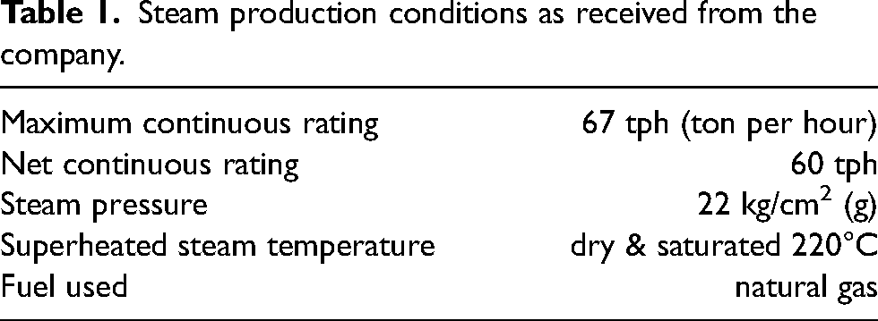
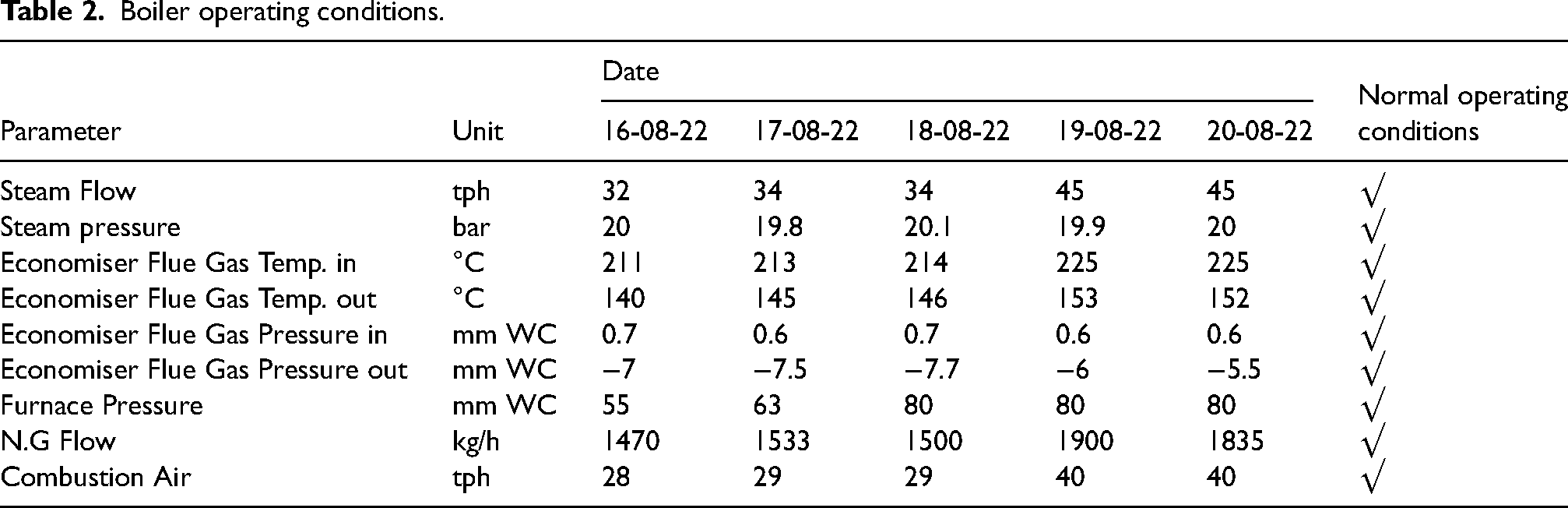
The equipment is a water tube boiler of natural circulation type, designed with forced draft and operated with natural gas. The steam is produced according to the conditions of Table 1. The upper part of the boiler stack fell down on the boiler roof structure after 12 years of installation. The boiler was running in an average condition, as shown in Table 2, with a load of 45 tph. There was no repair or failure in the previous 12 years of service. The average condition means within the design operating window. The data given in Table 2 are the average values of the different operation parameters, such as steam flow and steam pressure. These values were numerically averaged daily as shown in Table 2. Flue gases generated from combustion pass through the convection bank, lead to the economiser through the flue gas duct and finally into the atmosphere through the stack, as can be seen in Figure 1. The stack is a cylindrical steel chimney fabricated from carbon steel plates. It is 36 m in height and 0.9 m in internal diameter (it was supposed to be 2.5 m in the original design). The stack thickness varies from 12 mm at the bottom to 8 mm at the upper courses. The following was provided on the stack: (i) a drain connection was added at base ring for draining rainwater from the stack, (ii) access door was made for inspection and cleaning during shutdown and (iii) platforms at elevations +11000, +122500 and +33500 mm were constructed with ladder for accessing the stack external surface. The stack analyser was connected to the upper part of the stack. No conditional monitoring was done during the service life of the stack. In addition, the maintenance manual included no periodic checks of the stack. A severe metal loss was observed at the failure location.
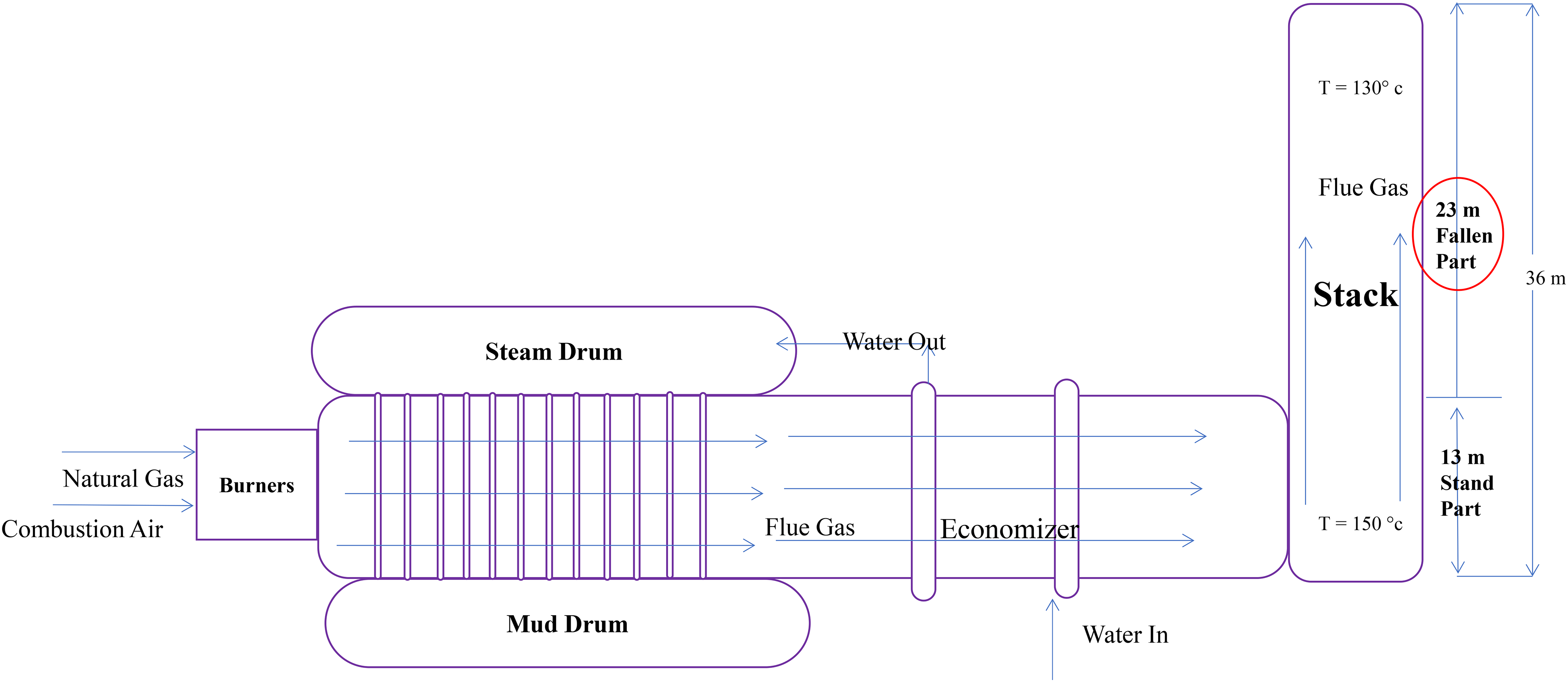
A schematic representation of the flue gas flow direction.
Steam production conditions as received from the company.
Boiler operating conditions.
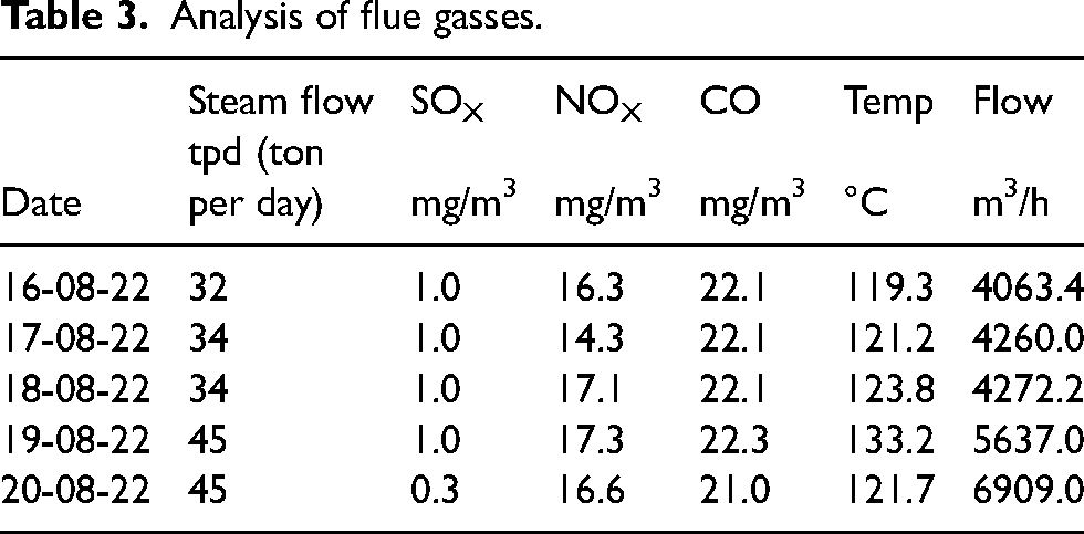
The received samples Sec 1 and Sec 2 were both at the failure location: one at the circumferential direction and the other one at the axial direction, respectively. The analysis of flue gasses was given by the owner company and shown in Table 3. It is clear from the flue gas analysis that there are levels of sulphur oxides, nitrogen oxides and carbon monoxide. These gases likely played a role in the observed corrosion/erosion failure.
Analysis of flue gasses.
The company asked for an answer specifically to the following questions:
The mechanism and root cause of the stack failure, and The recommendation to avoid future damages.
Chemical composition
The chemical composition of the corroded stack was obtained using an optical emission analyser, model ‘Foundry Master Pro, Germany’.
Visual examination
The received samples were visually inspected to investigate the type and amount of damage.
Microstructure investigation
To understand the microstructures of the failed samples and determine whether they contributed to the damage or not, a metallographic investigation was carried out using an optical microscope model ‘Olympus BX51’.
Analysis of corrosion products
A corrosion product sample was collected from the inner surface of the failed stack. The SEM model ‘JEOL’ combined with an EDS microanalyser was used to analyse the different elements and to understand their distribution in the corrosion products. The mineralogical analysis of the corrosion products was also determined using x-ray diffractometer. The XRD device is ‘BRUKER-D8 DISCOVER’, operating with Cu Kα radiation (λ = 0.154 Å), at 40 KV and 40 mA.
Hardness test
As a reliable indication of the mechanical properties, hardness was measured using a Vickers hardness tester at a load of 10 kg (HV10). An average of 5 measurements was considered.
Results and discussion
Chemical composition of the failed stack
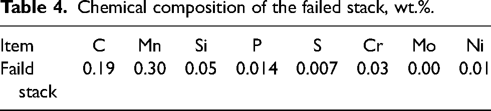
The chemical composition of the corroded stack is shown in Table 4. As can be seen the composition is plain carbon steel. Unfortunately, the specified steel grade of the stack is not known. Thus, no conformity can be made for the stack material. However, there are no uncommon elements or impurities in high levels (e.g., S and P) to which the failure might be attributed. Thus, the composition of the stack material constitutes no reason for failure.
Chemical composition of the failed stack, wt.%.
Visual examination results
Figures 2–4 show the failed stack and close-views of the received samples. The received samples were labelled Sec 1 and Sec 2. Both samples were taken from the same shell plate where the failure happened. Sec 1 was taken in the circumferential direction and Sec 2 in the axial direction. Both exhibit corrosion and severe gradual thinning to the location of failure. The inner surface of the stack plates shows some dark areas that might indicate high-temperature spots at/near the failure location (circled in Figure 3), even though the outside coating looks in good condition. The service history of the stack is necessary, especially for the previous temperature overshoots, the maintenance and the coating that were done for the stack. Unfortunately, this detailed information is not available.
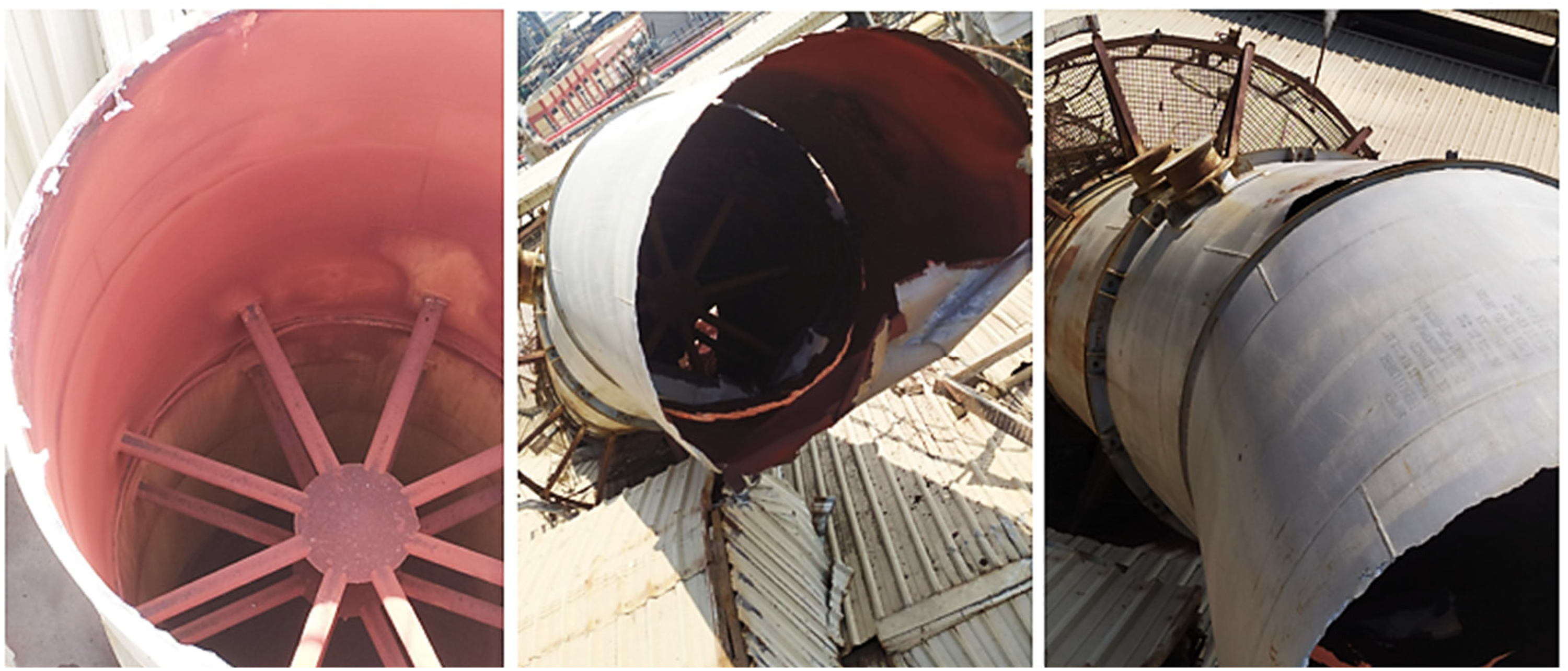
Photographs showing the failed stack.
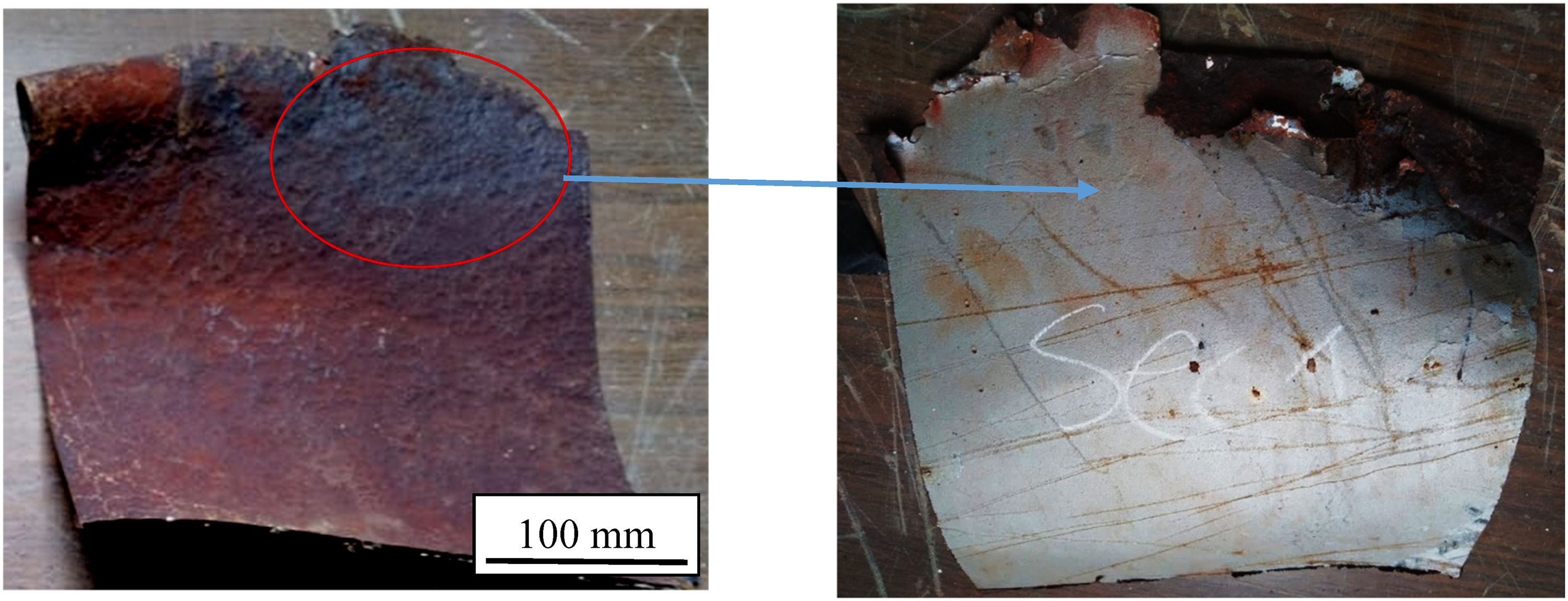
Samples from the failed stack, Sec 1 with severe thinning and erosion/corrosion.
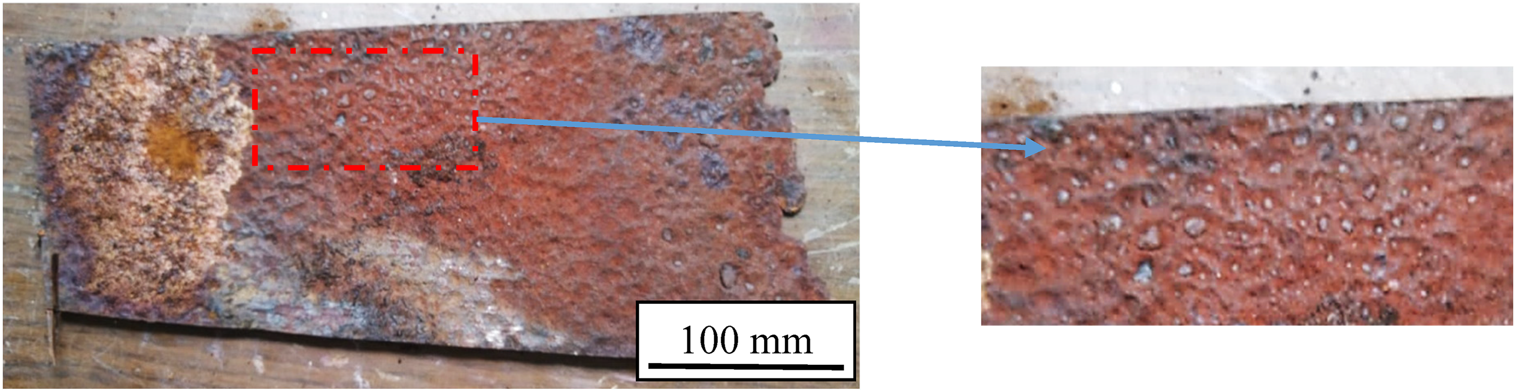
Samples from the failed stack, Sec 1 with severe thinning and erosion/corrosion.
The visual examination showed that there are no cracks at the different stack locations. However, thinning due to corrosion and/or erosion was found at several locations. Table 5 shows the ultrasonic thickness gauging of the stack. Severe metal loss was observed at the failure location. The minimum measured thickness was only 2.0 mm, while the design thickness for the lower section was 12 mm, and the upper section was 8 mm. The metal loss rate at the failure location was 0.67 mm/yr. Metal loss rate at top sections was estimated at 0.23 mm/yr.
Ultrasonic thickness measurements of the stack at different locations.
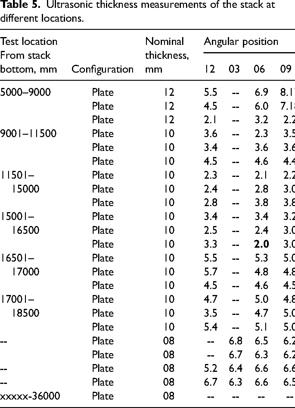
The appearance of the corroded surfaces either of Sec 1 or Sec 2 indicates some effect of erosion. The designed flue gas flow rate was between 4000 and 7000 m3/hr. The flue gas temperature was between 120 and 135°C. These values are within the normal operating conditions of the boiler. The flow rate of flue gasses was 6909 m3/hr. This yields a flow velocity of 23 m/min at a temperature of 121.7°C. These conditions most likely induce erosive/corrosive damage, especially when there are corrosive contaminants in the flue gases.
Figure 5(a) and (b) shows the macrographs of Sec 1 and Sec 2, corresponding to those of Figures 3 and 4, respectively. These two macrographs further clarify the substantial damage, most likely caused by severe corrosion attacks.
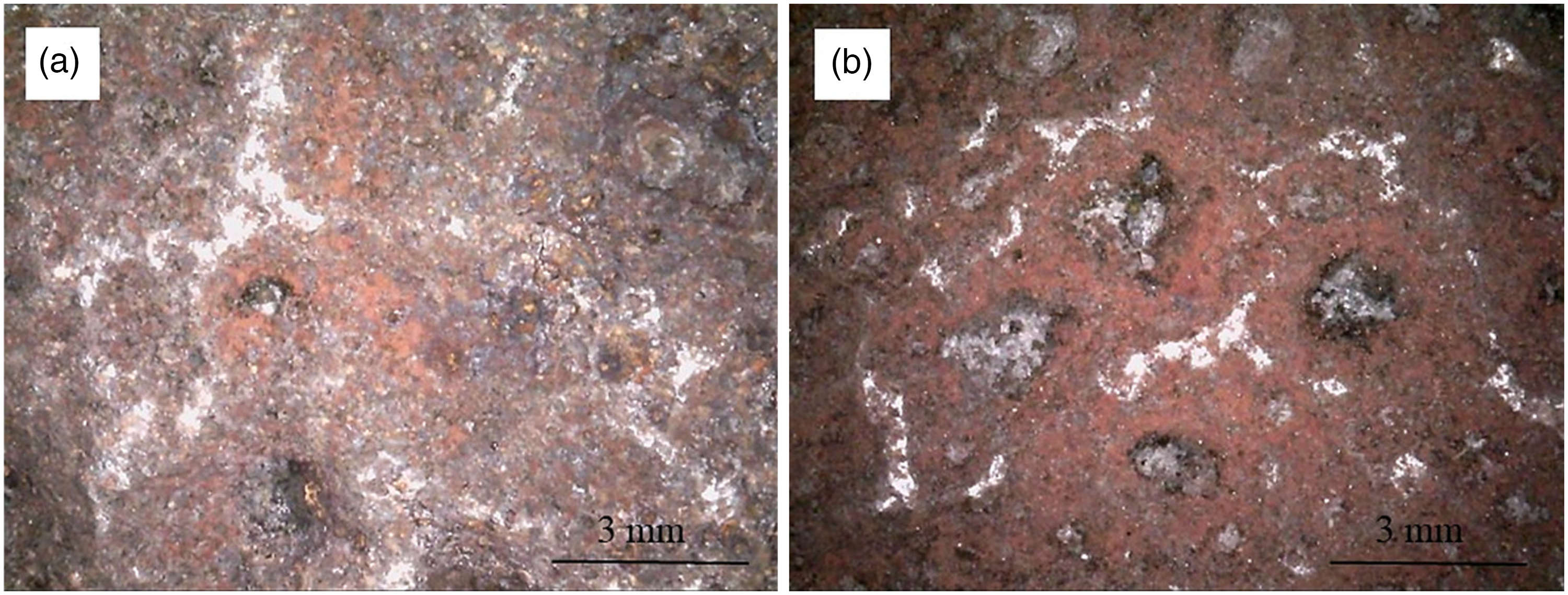
Macrographs of: (a) Sec 1, and (b) Sec 2, corresponding to Figures 3 and 4, respectively.
Microstructure characteristics
Figures 6 and 7 show the microstructures of the failed stack. Figure 6 shows the micrographs of Sec 1 at the location of failure. Pearlite spheroidisation occurred partially in these locations. This metallurgical phenomenon occurs when the carbon steel is exposed to a high temperature for an extended period. This typically takes place at temperatures of 44–760°C. This suggests that the exhaust gases went outside the design window of 190–270°C and continued for a long time. As learned from the company data, this temperature overshot did not occur.
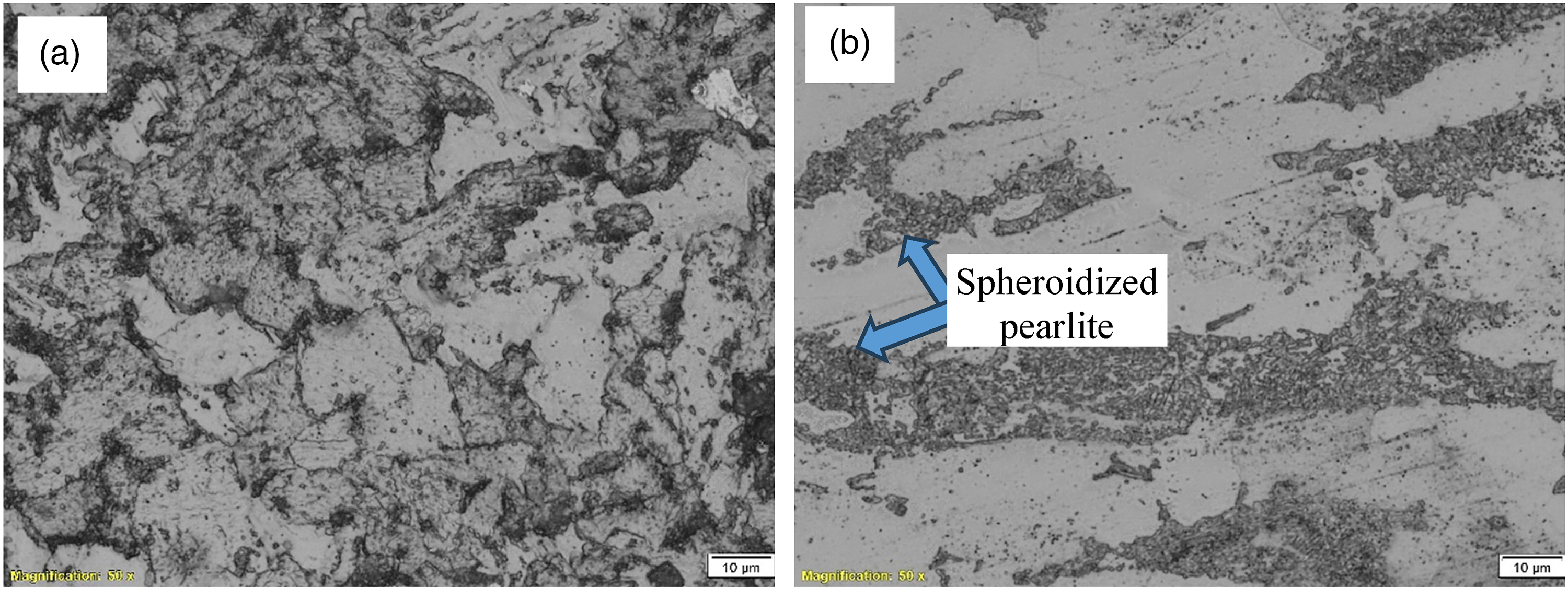
Microstructure of Sec 1: (a) partial spheroidisation of the pearlite, and (b) light etched micrograph showing more evident spheroidisation of pearlite. This indicates exposure to high temperature.
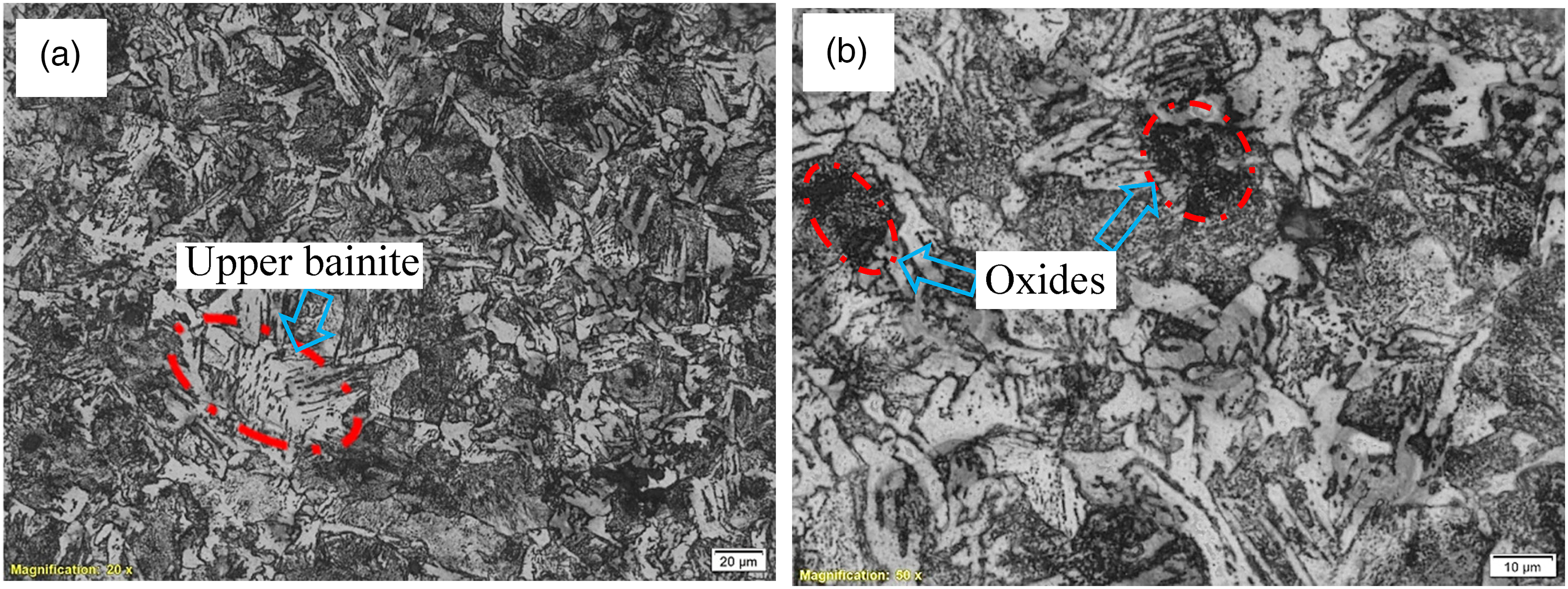
Microstructure of Sec 2 showing: (a) upper bainite phase which is only formed by rapid cooling from the austenite region, and (b) close-up view of image (a) showing additional dark areas of oxide. The stack material might be heated to a high temperature at ∼850°C, and then rapidly cooled.
Figure 7 shows the micrographs of Sec 2. The micrograph of Figure 7(a) shows the upper bainite phase. This indicates heating the steel to the austenite region (which is at about 850°C and higher), followed by rapid cooling. Figure 7(b) is a high-magnification micrograph showing the same, in addition to dark areas of the microstructure. These dark areas are likely oxide zones because of the excessive heating at high temperatures. These micrographs show a clear heat damage. This zone of the stack material was subjected to excessive heating to high temperatures, and then rapidly cooled. This likely occurred at the manufacturing phase before the erection of the stack.
Identification of corrosion products
Two types of analysis were used for the corrosion product identification: the SEM/EDS micro-elemental analysis, shown in Figures 8 and 9; and the XRD for mineralogical analysis of Figure 10. Both techniques give important details of the corrosion products.
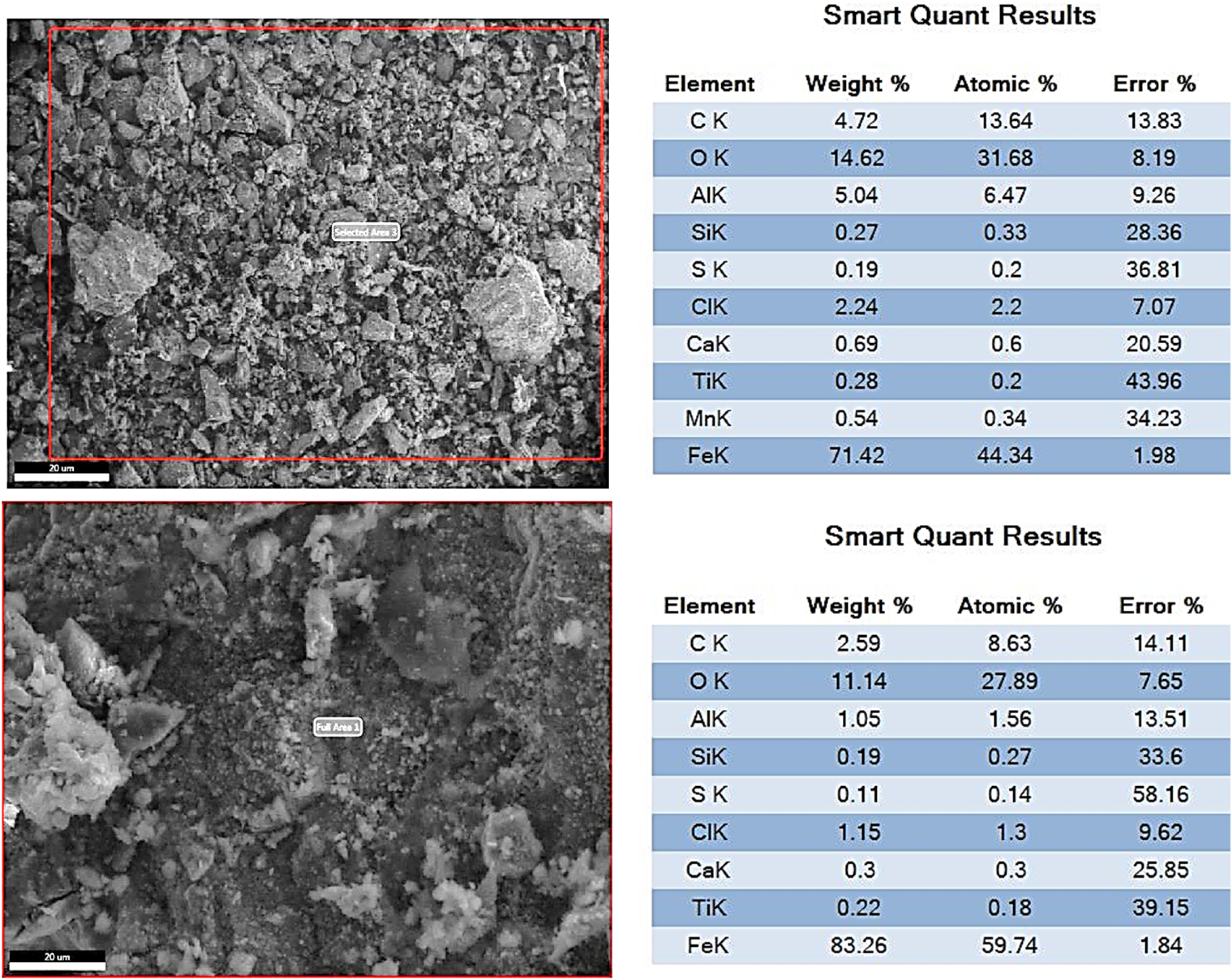
EDS analysis of the corrosion products of the inner surface of the failed stack.
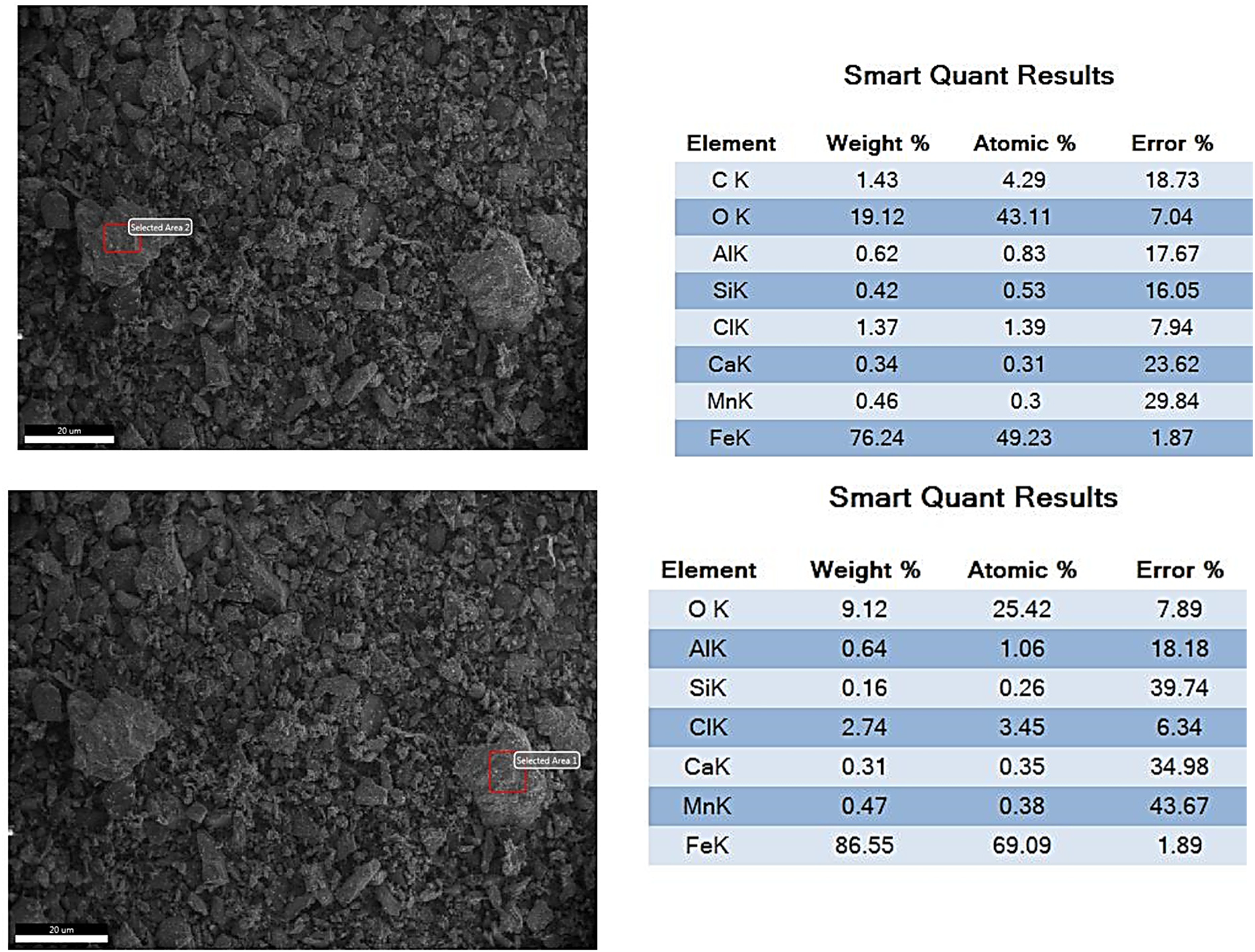
EDS analysis of some particles in the corrosion products of the inner surface of the failed stack.
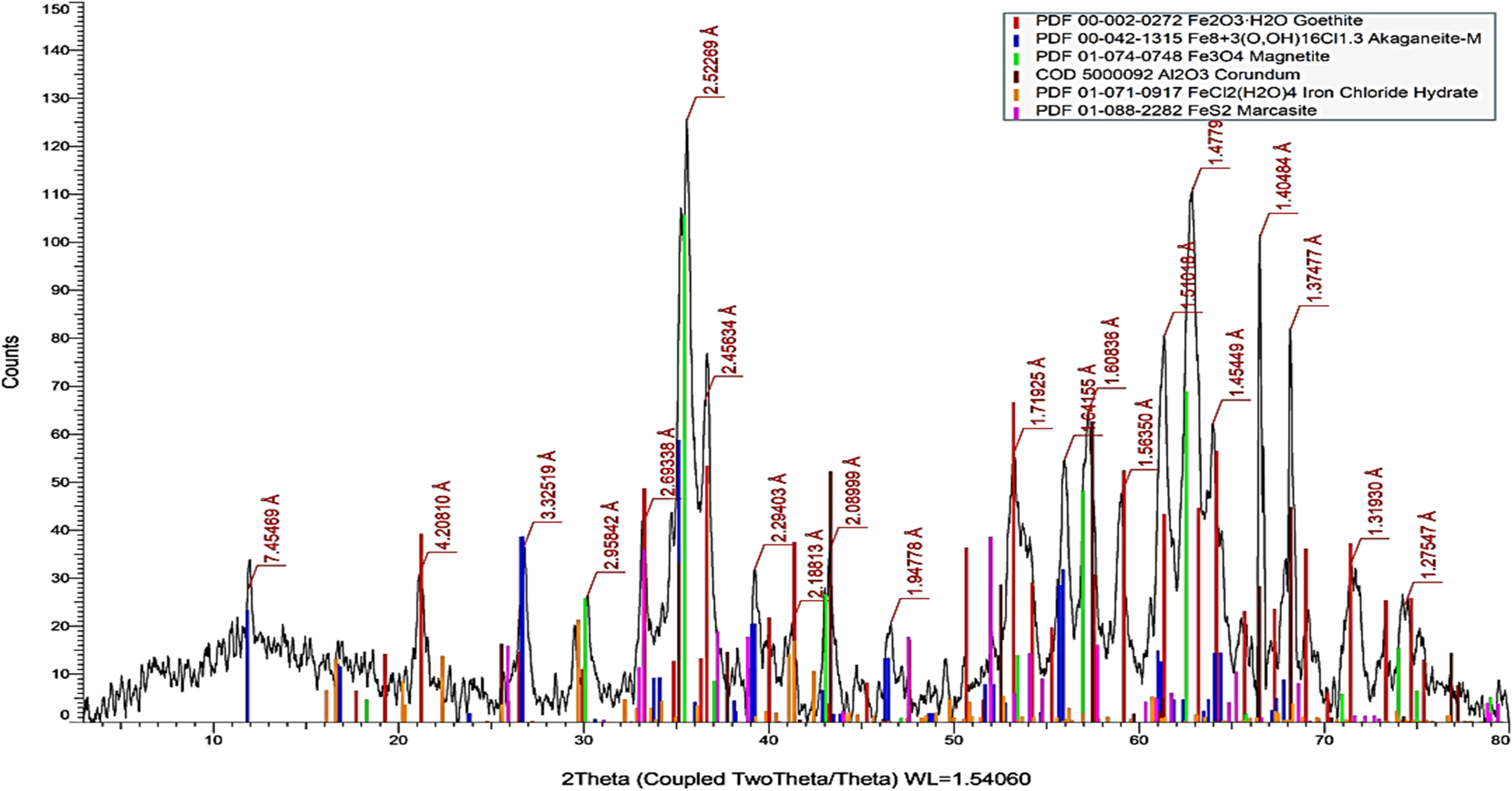
XRD pattern showing the mineralogical analysis of the corrosion products.
Figure 8 shows examples of the EDS analysis of the overall corrosion product, while Figure 9 shows the EDS analysis of selected particles in the corrosion products. According to these figures, the main compounds of the corrosion product are iron oxides, which are typical corrosion products of a steel stack. In addition, there are relatively large amounts of chlorine (Cl) and sulphur (S). Both of these elements are corrosive to the carbon steel stack. These are believed to be within the combustion products of the boiler fuel. Carbon is also a combustion product of the boiler fuel. The chlorides might be present as contaminants in fuel or in the coastal atmosphere, which is usually rich in chlorides. The sulphur might be a combustion product of some oil fuels. Gas fuels, on the other hand, are usually poor in sulphur compounds. It is also clear that the level of chlorides is much larger than that of sulphur.
In the current investigation, both Cl and S played a role in the observed corrosion. The form of corrosion might be a flue-gas dew-point corrosion as suggested by the owner inspection report. Figure 10, which represents the XRD pattern of the corrosion products, further confirms these findings. According to Figure 10, the predominant compound is magnetite (Fe3O4); followed by goethite (Fe2O3.H2O); Cl-containing compounds of akaganeite and iron chloride hydrate; and marcasite (FeS2).
Hardness results
Table 6 shows the results of hardness testing of the Sec 1 of the stack. The hardness was measured away from the highly thinned and failed location.
Hardness measurements.

Discussion
From the above results, it became evident that the stack material was subjected to high temperature, probably at the manufacturing stage or during boiler operation. In Sec 1, the heat exposure was held for a long period, so that the material underwent a spheroidisation/softening process. Softening is detrimental to erosion resistance. In Sec 2, the microstructure changed to upper bainite, which is an indication of heating to a high temperature of about 850°C and cooling rapidly. Both cases are signs of heat damage. There might be an attempt to increase the plate hardness by heat treatment (austenitising and quenching) to improve the erosion resistance of the stack material. But unlikely, the steel material of the stack is unsuitable for hardening by this technique because of its low carbon level. Instead, this would be achieved using harder alloys, hard-facing or surface-hardening treatments, whichever is feasible.
The corrosion products on the inner surface of the stack showed high levels of chlorine and sulphur. These elements are aggressive to carbon steel and likely played a major role in the observed flue-gas dew-point corrosion. This damage mechanism is mainly related to the condensation of sulphuric acid and/or hydrochloric acid at the stack internal walls. The dew-points for these acids are 138 and 54°C, respectively.12,13 The temperature of the flue gasses in the stack is generally between 150 and 130°C. Some measured values shown in Table 3 suggest that the flue gas temperature is about 120°C. Thus, condensation of some acidic solutions (sulphuric) likely took place.
Figure 11 is a schematic explanation of the dew-point corrosion in the current boiler stack. The condensation process of H2SO4 started to occur and the acid began to accumulate on the internal surface of the stack at about 138°C. Upon going upwards in the stack, the temperature decreases and the dew-point for HCl is reached (∼54°C). Then finally, water vapor condenses as well. All these condensed matters contributed to the stack surface damage by corrosion. It is worth mentioning that, the flue gas analysis given in Table 3 lacks the chlorine level, which was analysed in the stack rust and had played a major role in the observed failure. The chlorine level was not analysed since only three major gas components were regularly analysed due to their environmental impact. These are the sulphur oxides, the nitrogen oxides and the carbon monoxide. Thus, the absence of chlorine analysis does not mean it was not there, but simply means, it was not required, since the drive for these analyses was the environmental pollution.
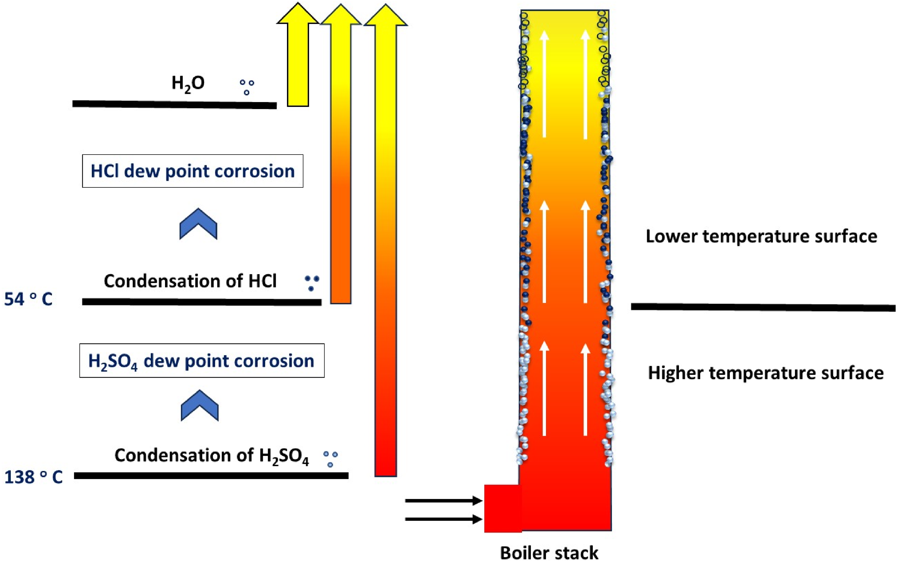
A schematic explanation of the dew-point corrosion process of the stack surface.
To mitigate this damage, it might be useful to maintain the stack surface above the temperature of sulphuric acid dew-point corrosion (i.e., 138°C). This would rule out the damage of dew-point corrosion of both the sulphuric and hydrochloric acids.
It is also believed that the flow rate plays part in this failure via the erosive effect of the flue gases at the failure location. The temperature of the flue gases also intensifies the corrosive and erosive factors of the damage. Therefore, the damage mechanism is a heat damage of the stack material, combined with the corrosive/erosive effects of the flue gases.
The company data exclude the boiler operation outside the boiler design window. Therefore, the root cause of the stack failure is the erosive action of the high-flow rate of flue gases and the corrosion effect of the flue gas condensation. Both of these affect the stack plates, which were primarily heat-damaged. One suitable remedy for the erosive action of the flue gases is to reduce the flow velocity by increasing the stack diameter.
Conclusions and recommendations
In the current investigation, failure analysis of a boiler stack was performed. The root cause of failure and the recommended actions are summarised as follows:
The root cause of the stack failure is a three-fold effect: the stack plates were primarily heat-damaged, in addition to the erosive and corrosive actions of the flue gasses. The heat damage led to spheroidisation/softening of stack material, and the microstructure changed to upper bainite at other locations. The high-flow rate of gases caused erosion and thinning of the stack wall. The main damage was the dew-point corrosion. Condensation of sulphuric and/or hydrochloric acid occurred at the stack internal walls causing corrosion. Improve the resistance to erosion by increasing the hardness of the stack material using harder material or any suitable alternatives. Minimise the dew-point corrosion by maintaining the stack metal surface above 138°C. Increase the stack diameter to decrease the gas velocity and reduce the erosive damage. Utilise suitable NDT techniques and thickness gauging to inspect and monitor the stack shells regularly, in order to avoid sudden failures.
The recommendations of this study are:
Footnotes
Data availability
All data generated or analysed during this study are included in this published article.
Declaration of conflicting interests
The authors declared no potential conflicts of interest with respect to the research, authorship and/or publication of this article.
Funding
The authors received no financial support for the research, authorship and/or publication of this article.