






Abstract
Keywords
Introduction
Endovascular aneurysm repair (EVAR) has been continuously evolving over the past 2 decades. Although EVAR is minimally invasive and is associated with lower mortality as compared with conventional open surgical repair, certain groups of patients remain unsuitable for EVAR due to unfavorable abdominal aortic aneurysm morphology, such as short neck, conical and/or angulated aortic neck, calcified aortic wall, and atheroma deposits. Fenestrated and branched stent-grafts were introduced to overcome some known anatomic limitations of standard EVAR.
Fenestrated stent-grafts (FSGs) are customized devices in which fenestration(s) in the main endograft are aligned with the ostia of one or more visceral arteries and secured to these target vessels by covered stents that protrude into the visceral vessel(s).1–6 These fenestrated vessels provide a seal that excludes any blood flow from entering the aneurysm sac while providing an additional anchoring force to safely secure the endograft. Off-the-shelf branched stent-grafts (BSGs) can be seen as successors to FSGs because the length of seal between the main endograft and the visceral vessel branch is much longer as compared with an FSG, where the entire sealing zone consists of only the metal ring surrounding the fenestration. 5 A BSG also makes it easier for the interventionists to cannulate the visceral arteries as the inner docking lumen in the main endograft provides room for additional maneuvering.
Schematics of an FSG and a BSG are shown in Figure 1. Although BSGs are conceptually more appealing than FSGs with respect to branch stability and ease of implantation, there are a number of critical questions that must be answered to ensure durable device design. Some of these key questions are (1) the hemodynamic impact of antegrade and retrograde blood flow on the functionality of the BSG 7 and (2) the consequences of misaligned visceral stent-grafts 4 on the durability of both FSGs and BSGs. Answering these questions will help to assess the reliability of both stent-grafts for EVAR, which may aid surgeons in predicting the likelihood of future complications, such as migration and endoleaks, as well as intimal hyperplasia and occlusion.

Schematics of the modeled branched stent-grafts (BSGs) and fenestrated stent-graft (FSG). Antegrade BSGs are shown in column 1, retrograde BSGs in column 2, and FSGs in column 3. Outlets 1 and 2 are labeled in antegrade BSG with takeoff angles of 90°; the terminology is consistent for all the other stent-grafts.
The objective of this study was to answer the 2 aforementioned questions by simulating blood flow in ideal models of a FSG and a BSG under physiologic conditions using computational fluid dynamics. Both antegrade and retrograde BSGs were examined, and FSGs with the same renal outlet configuration were also analyzed to allow direct comparison of the results. Key outcomes that were scrutinized in this study include the recirculation zones in renal branches, the outflow in the renal and iliac arteries, and the resultant displacement force experienced by the stent-grafts to assess the risk of device migration.
Methods
Computational fluid dynamics simulations require construction of a 3-dimensional (3D) geometric model for the fluid domain of interest, specifying assumptions made in the governing equations and physiologically relevant boundary conditions, and choosing an appropriate numeric scheme to solve the set of coupled equations. For this simulation, idealized 3D models of stent-grafts were constructed using commercially available software SolidWorks (Dassault Systemes, Velizy, France). In order to account for misaligned visceral stent-grafts, 3 different takeoff angles (ToAs) between the main stent-graft body and the visceral stent-graft centerline axis were considered: 90° to represent normal alignment and 30° and 120° to represent misaligned renal outlets of the BSGs and FSGs. The effect of aortic neck angulation on the performance of BSGs and FSGs was evaluated by building additional models with ToAs of 90° and a 60° lateral aortic neck angulation. Schematics of all the studied stent-grafts together with definitions of visceral ToAs and lateral aortic neck angle are further explained in Figures 1 and 2.

Schematics illustrating the definition of takeoff angle (ToA) and lateral aortic neck angle (planar) used in this study.
For all the analyzed BSGs and FSGs, the inlet diameter to renal diameter ratio was set at 44,7; the inlet diameter to iliac diameter ratio was set at 1.54, while the iliac bifurcation angle was fixed at 30°. For antegrade and retrograde BSGs, the lengths of each visceral cuff inside the main endograft were 8 and 15 mm, respectively. Surface areas of antegrade BSGs, retrograde BSGs, and FSGs were 15,817, 16,336, and 15,252 mm2, respectively. A 20-mm-long cylindrical segment was added to the inlet, while the visceral (renal) arteries were artificially extended by 30 mm in order to ensure that the resolved flow field was not influenced by the location of the inlet and outlet boundaries.
Conservation of mass, momentum, and energy equations were used to describe the laminar pulsatile blood flow in the lumen. Since blood flow in a human body can be assumed to be incompressible and isothermal, the energy conservation equation was not needed, and the resulting governing equations consisted of continuity and Cauchy momentum equations. 6 Blood was assumed to be a non-Newtonian fluid described by the Quemada viscosity model. A physiologically realistic volumetric flow rate waveform was extracted from the literature 8 and was imposed at the inlet, along with Womersley velocity profiles. 9 Corresponding pressure waveforms obtained by coupling the outlet of each terminal vessel with a 3-element windkessel model (3-EWM) were prescribed at the outlets. The parameters of the 3-EWM, that is, proximal resistance R1, distal resistance R2, and compliance C, were obtained using the Nelder–Mead Simplex algorithm. No slip boundary conditions were specified at the stent-graft walls, which were assumed to be nondistensible. In order to delineate the effect of geometry on hemodynamics in stent-grafts, the same set of boundary conditions were applied to all computational models concerned in this study. The inflow waveform expressed in terms of instantaneous Reynolds number, along with the schematic of the employed computational model, is shown in Figure 3.
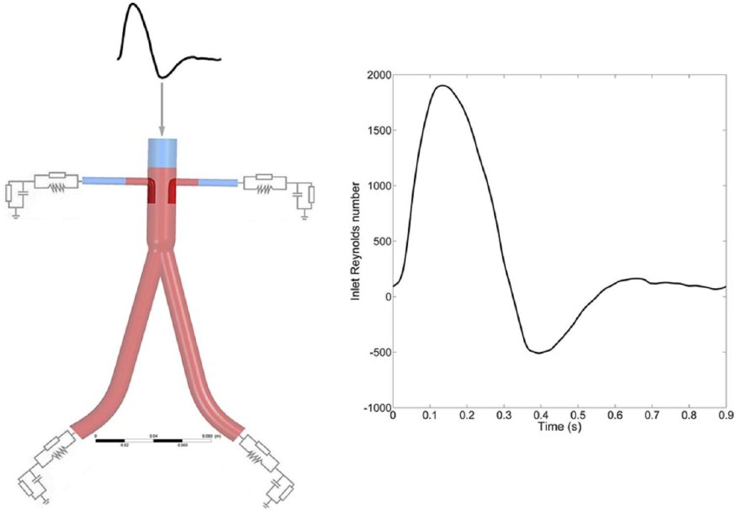
Schematic of the computational model adopted in the study along with the inflow waveform, shown here in terms of instantaneous Reynolds number.
The 3D stent-graft models were discretized into tetrahedral and prism elements using ANSYS ICEM CFD (ANSYS, Canonsburg, PA, USA). The governing equations were solved numerically using ANSYS CFX. In order to achieve well-converged solutions, a convergence criterion based on a root mean square residual was set to be 1×10⁻⁶. A uniform 0.001-second time-step was used, and all simulations were performed for three cardiac cycles in order to achieve periodicity. 6
Grid independence tests were carried out, and the results were declared grid independent when velocity fields and displacement forces did not alter by ±2% between 2 successive meshes. For the studied geometries, a minimum of 350,000 elements were required to achieve grid independence. The number of elements adopted in the final analysis ranged from 1.5 million to 1.8 million.
The formation of flow recirculation zones (FRZs) is one of the most important flow phenomena in the renal branches and is caused by a sudden change in flow direction at the renal bifurcation; the size and location of FRZs are strongly dependent on local geometry. FRZs in the renal branches were quantified by measuring the distance between the flow separation and reattachment points (Figure 4A), following the method proposed by Kenwright et al. 10 It is important to identify and compare FRZs in renal branches because these regions are associated with low wall shear stress (WSS) and are therefore prone to increased risk of thrombus formation.11–13 In addition, all stent-grafts experience time-dependent displacement forces, which are generated due to blood pressure and friction exerted by blood flow on stent-graft walls. 14 Large displacement forces are related to future complications, such as endograft migration and type I endoleaks, therefore it is critical to quantify these forces. Displacement forces were calculated by integrating the traction vectors, pressure, and WSS over the entire surface of the BSGs and FSGs in coronal, sagittal, and transverse directions. The association between ToAs and displacement forces was explored in multiple linear regression analysis.
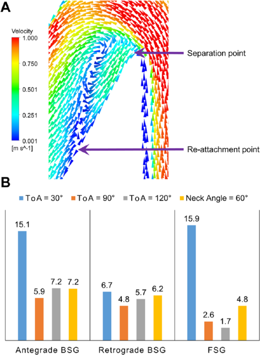
(A) Velocity vectors highlighting the separation point and reattachment point that define the flow recirculation zone (FRZ) found in renal branches. (B) Bar chart showing the lengths of FRZ (mm) in all the stent-grafts examined. For antegrade branched stent-grafts (BSGs) and fenestrated stent-graft (FSG) at ToA of 30°, the length shown here corresponds to the sum of the 2 FRZs found in each case.
In order to evaluate the performance of all stent-grafts for every visceral ToA and lateral aortic neck angle, results are presented and discussed with regard to the FRZs in the renal arteries, the renal and iliac flow rates for the BSGs vs FSGs, and finally, displacement forces experienced by the BSGs and FSGs.
Results
Recirculation Zones in the Renal Arteries
The instantaneous time point of maximum deceleration (Tb=0.3 seconds) was chosen to compare FRZs in the renal arteries for all stent-grafts because this is the time point when the largest FRZ were observed. As summarized in Figure 4B, the largest FRZs were found in antegrade BSGs and FSGs at ToA of 30°, while the smallest FRZ was observed in FSGs at ToA of 120°. At ToA of 30°, the length of FRZs in the antegrade BSGs and the FSG was significantly larger than that of the retrograde BSG, because there were 2 FRZs in each of the antegrade BSGs and the FSG and the reported length was the sum of the two lengths. Of all the geometric variations of stent-grafts studied here, the minimum standard deviation in length of the FRZs was found in the retrograde BSGs (0.8 mm), while the maximum was found in the FSG (6.6 mm). Locations of the FRZs can be seen from the time-averaged wall shear stress (TAWSS) contours in Figure 5, which also demonstrate large spatial variations of WSS in the renal branches.

Time-averaged wall shear stress (TAWSS) contours for stent-grafts with straight aortic neck and takeoff angle (ToA) of (A) 90°, (B) 30°, and (C) 120° and (D) for stent-grafts with a lateral aortic neck angle of 60° and a ToA of 90°. Locations of flow recirculation zones are marked by arrows that also correspond to regions of low TAWSS.
Swirling Patterns in the Main Body of Stent-Grafts With Straight and Angulated Necks
For stent-grafts with a straight aortic neck, 4 symmetric swirling zones were found in the main endograft body, distal of the renal ostia, as shown in Figure 6A. However, in stent-grafts with 60° lateral aortic neck angles, only 2 swirling zones were found in the main endograft body, distal of renal ostia, as shown in Figure 6B.

Swirling flow patterns in main endograft body of (A) stent-graft with straight aortic neck and (B) stent-grafts with lateral aortic neck angle of 60°, at instantaneous time point of Tb=0.3 seconds, which corresponds to the maximum flow deceleration. Only retrograde branched stent-grafts are shown, as similar patterns were observed for all the other stent-grafts. FRZ, flow recirculation zone.
Comparison of Renal and Iliac Flow Rates Between BSGs and FSGs With Straight Necks
Based on our numeric simulation results, there was an equal flow division between the left and right renal arteries in all stent-grafts with a straight aortic neck, and the same was found for the left and right iliac arteries owing to geometric symmetry. For all the simulated scenarios, the renal flow waveform was characteristically different from the iliac flow waveform, such that in renal arteries, the instantaneous flow rate was antegrade throughout the cardiac cycle, with relatively high diastolic flow, as compared to flow in the iliac arteries. As shown in Figure 7, the maximum renal flow was observed for FSGs and the minimum flow for retrograde BSGs for all ToAs examined. In antegrade BSGs, renal flow was as high as in the FSGs during systolic acceleration, but soon after peak systole, renal flow dropped down to about the same level as in the retrograde BSGs. Table 1 gives a summary of the cycle-averaged renal flow for all the stent-grafts and ToAs in this study.

Renal (left) and iliac (right) flow rate waveforms over one cardiac cycle for all the stent-grafts with a straight aortic neck and takeoff angles of (A) 90°, (B) 30°, and (C) 120°.
Cycle-Averaged Flow Rate in the Renal and Iliac Arteries for All Stent-Grafts With a Straight Aortic Neck at Different Takeoff Angles.

Abbreviations: BSG, branched stent-graft; FSG, fenestrated stent-graft; ToA, takeoff angle.
Iliac flow waveforms for all the studied stent-grafts at every ToA are also included in Figure 7. The time dependence of iliac flow waveforms was very similar to the inlet flow waveform. In contrast to renal flow waveform, during early systole, the maximum flow was observed for retrograde BSGs, and after peak systole, especially at late diastole, blood flow in the iliac arteries settled at almost the same value for all the stent-grafts. The peak systolic flow rate for iliac arteries was 4 times higher than the peak systolic renal flow in FSGs. However, just like the inlet flow rate waveform, there was flow reversal in the iliac arteries during early diastole, and average late diastolic flow was almost zero. Cycle-averaged mean flows in the iliac arteries for all the stent-grafts at every visceral ToA are also summarized in Table 1.
Comparison of Renal and Iliac Flow Rates Between BSGs and FSGs With Angulated Necks
With an angulated aortic neck, the BSG and FSG models became asymmetric; thus, the flow division between the two renal branches was no longer equal, especially during early systole when the flow was accelerating (Figure 8). The results show that peak systolic flow through outlet 1 was higher in retrograde BSGs but lower in FSGs and antegrade BSGs. Cycle-averaged renal and iliac flow rates for all stent-grafts with an angulated neck are summarized in Table 2. The iliac flow waveforms for stent-grafts with an angulated aortic neck followed the same trend as that of stent-grafts with a straight aortic neck.

Renal (left) and iliac (right) flow rate waveforms over one cardiac cycle for stent-grafts with a lateral aortic neck angle of 60° and takeoff angle (ToA) of 90° for (A) antegrade and (B) retrograde branched stent-grafts and (C) fenestrated stent-grafts.
Cycle-Averaged Flow Rate in the Renal and Iliac Arteries for All Stent-Grafts With a Lateral Aortic Neck Angulation of 60° and a Takeoff Angle of 90°.

Abbreviations: BSG, branched stent-graft; FSG, fenestrated stent-graft.
Refer to Figure 1 for schematics of outlets 1-4.
Displacement Forces Experienced by BSGs and FSGs With Straight and Angulated Necks
Time dependence of displacement forces acting on all the stent-grafts followed the pressure waveform very closely, as shown in Figure 9A, for the straight aortic neck models with a ToA of 30°. The peak displacement force for all the stent-grafts was observed at t=0.3 seconds, corresponding to the time point of peak aortic pressure. In stent-grafts with a straight aortic neck, it is evident from Table 3 that the magnitude of the displacement forces depends very strongly on the ToA (R2=0.998) and lateral aortic neck angle but not on the type of stent-graft. A mean (cycle-averaged) displacement force of 1.95 N was observed for BSGs and FSGs at ToA of 120°, while a mean displacement force of 1.24 N was observed for these stent-grafts at 30° ToA. At ToA of 90°, an intermediate mean displacement force of 1.69 N was observed for all types of stent-grafts. The maximum mean displacement force for stent-grafts with a straight neck at ToA of 120° increased by 86.2%. Displacement force is a 3D vector with components in the coronal, sagittal, and transverse planes. However, as the constructed stent-grafts with straight aortic necks were planar and symmetric, all the displacement forces were acting vertically downward in the coronal plane (Figure 9B). The cycle-averaged angle between the x-axis and the displacement force was 90°.

(A) Time variation and magnitude of the displacement forces acting on all the stent-grafts with a straight aortic neck at takeoff angle (ToA) of 30°. Time dependence of displacement forces follows the cardiac pressure waveform very closely, and this trend holds true for all the other stent-grafts. The magnitude of the displacement force changes with ToA and aortic neck angle: (B) direction vector (red arrow) for the resultant displacement force for all stent-grafts with a straight aortic neck and (C) direction vector (red arrow) for the resultant displacement force for all stent-grafts with an angulated aortic neck.
Cycle-Averaged Displacement Forces Acting on All Stent-Grafts With a Straight Aortic Neck at Different Takeoff Angles and All Stent-Grafts With a Lateral Neck Angle of 60°.

Abbreviations: BSG, branched stent-graft; FSG, fenestrated stent-graft; LNA, lateral neck angle.
The time trend for displacement forces observed for stent-grafts with different ToAs also holds true for stent-grafts with a lateral aortic angle. That is, not only the displacement force followed the aortic pressure waveform very closely but also the same displacement force was recorded for antegrade and retrograde BSGs, as well as FSGs with an aortic neck angle of 60°, both in terms of time dependence and magnitude. The peak displacement force for all the stent-grafts with an angulated neck was found to be 5.27 N, while the minimum and mean displacement forces were 2.69 and 3.65 N, respectively. As angulated stent-grafts were planar but asymmetric, displacement force was no longer acting vertically downward (Figure 9C), and the cycle-averaged angle between the x-axis and the displacement force was 6.25°.
Discussion
Fenestrated stent-grafts are customized on a patient-specific basis to ensure that the fenestrations in the main endograft body are aligned properly with the visceral arteries. These fenestrations then house the supplemental stent-grafts that protrude into visceral arteries, so that the aneurysm sac is separated from blood flow while the visceral (renal) stent-grafts provide additional anchoring force to prevent device migration. Because of the presence of these fenestrations, tailor-made FSGs require several weeks in the manufacturing process, rendering their use expensive and unsuitable for urgent cases. FSGs are also susceptible to intra- and interobserver discrepancies,15,16 which can lead to potentially misaligned visceral stent-grafts. Misalignment affects their patency, which can lead to branch occlusion. One can therefore argue that the unique advantage of FSGs is also their biggest drawback. In order to overcome these limitations of FSGs, antegrade and retrograde BSGs were introduced. 17 BSGs have a fixed stent-graft that is parallel and anastomosed to the proximal part of the main endograft. These fixed stent-grafts can be oriented in either antegrade or retrograde fashion and house the docking point for visceral stent-grafts, thus eliminating the need for custom-made fenestrations and make them adaptable to a wide variety of hostile anatomies. The overall objective of this study was to use computational fluid dynamics simulations to evaluate the hemodynamic consequences of antegrade and retrograde BSGs as compared with FSGs at various visceral ToAs and lateral aortic neck angles.
Persistent FRZs were identified in renal arteries (outlets 1 and 2) of most stent-grafts, and the largest FRZs were observed at the time point of maximum flow deceleration, Tb (0.3 seconds). Flow in FRZs is disturbed, resulting in low WSS (as shown in Figure 5), which has been associated with the development of atherosclerotic plaques. The presence of permanent FRZs may also favor thrombus formation, leading to partial or complete occlusion of the visceral branch and sometimes distal embolization. Therefore, large and permanent FRZs should be avoided as much as possible. For stent-grafts with a straight neck, as summarized in Figure 4, two features can be observed: (1) The FRZs were much larger in the antegrade and retrograde BSGs than in the FSGs except for ToA of 30, and (2) the size of the renal FRZs in BSGs depends very strongly on the renal ToA, as the largest FRZs were found in BSGs at 30° ToA.
The presence of FRZs caused large spatial variations in TAWSS near the renal junction, as shown in Figure 5A–C. For stent-grafts with an angulated aortic neck, however, FRZs in the renal arteries varied differently from those found in stent-grafts with a straight aortic neck. With aortic neck angulation of 60°, the flow was directed toward one side of the endograft due to inertia, ie, toward outlet 2 (right renal artery), thus FRZs in the right renal branches were not mirror images of the ones found in the left, as reflected in the TAWSS contours in Figure 5D.
Lateral neck angulation also has a strong effect on the flow swirling patterns in the main endograft body distal to the renal ostia, as shown in Figure 6. The experimental study carried out by Ha and Lee 18 demonstrated the beneficial effects of pulsatile swirling flow, namely, reduction of the oscillatory shear index and the propagation length of jet flow.
Volumetric flow rate waveforms in renal arteries are characteristically distinct from iliac arteries because of relatively low resistance of the distal vascular beds of the kidneys, 19 thus avoiding any backflow throughout a cardiac cycle. As shown in Figure 7 and Table 1, retrograde BSGs had the lowest renal flow rate at all ToAs examined, while the highest renal flow was achieved in FSGs. A complete opposite trend was observed in iliac arteries, with the highest flow in retrograde BSGs and lowest in FSGs. This is dictated by the conservation of mass, so that stent-graft inflow must be balanced by the sum of outflow through the renal and iliac arteries. For antegrade and retrograde BSGs with ToA of 90°, outflow into each renal branch was 0.08 L/min higher in antegrade than retrograde BSGs. Computational simulations carried out by Sutalo et al 7 on a simplified model of BSGs with a ToA of 90° also found a similar trend. They reported that outflow into renal branches of antegrade BSGs was 0.07 L/min higher than that of retrograde BSGs for a 200-mm conduit; the difference was reduced to 0.03 L/min for a 40-mm conduit. Although our results are in qualitative agreement with those of Sutalo et al, 7 some quantitative differences exist, which can be attributed to the different stent-graft model geometry and flow conditions employed in the 2 studies. Sutalo et al 7 examined a single branch conduit without including the iliac bifurcation, whereas our model incorporated two parallel branch conduits and the iliac bifurcation. Moreover, we applied a realistic abdominal aortic flow waveform based on the in vivo study of Fraser et al. 8
Regarding the effect of ToA on renal flow, Table 1 shows clearly that an antegrade BSG is less sensitive to ToA than retrograde BSGs and FSGs. When renal ToA reduced from 90° to 30°, mean renal flow reduced by 0.04 L/min for retrograde BSGs and 0.03 L/min for FSGs. As ToA increased from 90° to 120°, no change in renal flow was found in retrograde BSGs, while mean flow rate decreased by 0.02 L/min in FSGs. These results indicate that renal flow in retrograde BSGs is sensitive to ToA, and an acute ToA (eg, 30°) tends to reduce renal flow; however, the quantitative effect of ToA on mean renal flow is relatively minor.
For stent-grafts with lateral neck angulation, the flow division between renal outlets 1 and 2 was not equal (Figure 8). The asymmetry in flow between the left and right renal arteries was amplified at peak systole. This is because blood flowing at a high velocity tends to keep flowing in the same direction. Because of sharp angulation, the blood close to the inner wall does not have enough centripetal force to flow along the same path and centrifugal force becomes predominant. As a result, flow tends to favor the branch that requires less change in flow direction. By comparing Tables 1 and 2, it is clear that an angulated aortic neck caused a slight increase in renal flow. Compared with straight-neck stent-grafts, total mean outflow into the renal arteries was 0.04 L/min higher in retrograde BSGs with an angulated aortic neck and 0.01 L/min higher in FSGs. For antegrade BSGs, there was a slight reduction of 0.01 L/min in each renal artery. This can be explained by the fact that aortic neck angulation gives rise to secondary motion in the main stent-graft body (as shown in Figure 5D), and this secondary motion helps divert blood to renal branches in retrograde BSGs and FSGs, thus yielding slightly improved renal flow. However, just like stent-grafts with a straight aortic neck the maximum renal flow was observed in angulated FSGs, followed by antegrade BSGs while minimum flow rate was observed in retrograde BSGs.
With respect to displacement forces acting on the stent-grafts, it can be seen from Table 3 that the magnitude of cycle-averaged displacement force is dependent more on ToA rather than the orientation of the stent-graft. Linear regression analysis between ToA and displacement forces yielded an R2 value of 0.998 for BSGs and FSGs, suggesting that displacement force increased almost linearly with ToA. Nevertheless, the increase in the magnitude of displacement force with ToA was relatively small compared with the change brought on by aortic neck angulation. When ToA increased from 30° to 90°, the cycle-averaged displacement force increased from 1.25 to 1.69 N, but when neck angle changed from straight to 60° for a ToA of 90°, the mean displacement force was more than doubled from 1.69 to 3.6 N. Therefore, the results suggest that the displacement force experienced by stent-grafts is more sensitive to lateral aortic neck angle than ToA. This is consistent with the finding of Georgakarakos et al, 4 who reported that with increasing ToA, the value of displacement force did not vary much from 5.55 N. It is interesting to note that Georgakarakos et al 4 reported a higher value of displacement force than those found in this study. This difference is mainly attributed to the different dimensions of the stent-grafts and their nonplanarity; the stent-graft models examined in the present study were planar, whereas those adopted by Georgakarakos et al 4 were nonplanar. As shown in patient-specific study carried out by Kandail et al, 6 the magnitude of displacement force depends very strongly on nonplanar anterior–posterior angle, and increasing the anterior–posterior angle can significantly increase the magnitude of the displacement force.
Conclusion
Our computational simulations clearly show that all the stent-grafts examined provide adequate perfusion to the visceral (renal) arteries, even when the visceral stent-grafts are misaligned. Renal flow rate is higher with antegrade BSGs than retrograde BSGs, although FSGs offer the highest renal flow. However, misaligned renal stent-grafts give rise to FRZs in the renal arteries that may become potential sites for thrombus formation or stenosis. The size of the renal FRZs depends strongly on the angle between the BSG and the renal artery. Because of comparable dimensions of the antegrade, retrograde, and fenestrated stent-grafts, the displacement forces acting on the stent-grafts are independent of their type but dependent on the degree of misalignment and lateral aortic neck angle, with the latter being a more important determinant of the displacement force.
Footnotes
Declaration of Conflicting Interests
The author(s) declare no potential conflicts of interest with respect to the research, authorship, and/or publication of this article.
Funding
The author(s) report receiving the following financial support for the research, authorship, and/or publication of this article: This research is sponsored by a Doctoral Training Grant from the Engineering and Physical Sciences Research Council, UK.