
Abstract
Melt electrowriting (MEW) is an emerging additive manufacturing technology capable of depositing continuous micro- and submicron-fibers for the fabrication of high-resolution fibrous scaffolds. In this process, jet lag is a distinctive phenomenon that critically affects both process stability and printing accuracy, yet its real-time measurement remains challenging, especially during nonlinear printing. This study developed a machine-learning-assisted framework to predict jet lag length in MEW from five key process parameters: voltage, collector speed, material temperature, nozzle-to-collector distance, and air pressure. Multiple linear regression and random forest were comparatively evaluated. Both models achieved effective prediction, while random forest showed higher predictive accuracy. This improvement is attributed to its greater flexibility in representing potential nonlinear dependencies within the current dataset. The predictive performance of random forest was further validated through the printing of high-accuracy nonlinear fiber patterns. These findings demonstrate the feasibility of data-driven jet lag prediction and provide a practical framework for improving printing accuracy in MEW.
1. Introduction
Since its inception in the 2010s, melt electrowriting (MEW) has rapidly evolved as a key technique for fabricating fiber scaffolds from microscale fibers.1,2 Combining melt electrospinning with additive manufacturing,3,4 MEW uniquely enables independent control over fiber diameter (typically 5-50 μm) and placement.5,6 These advantages, together with its solvent-free process, 7 significantly expand its applications in tissue engineering and regenerative medicine.8,9
As an extrusion-based additive manufacturing approach, MEW shares similarities with fused deposition modeling (FDM), particularly in system configuration. 3 This similarity prompted Reizabal et al. to adapt an open-source Voron 0.1 printer into a MEW device (“MEWron”). 10 These similarities also enabled Jin et al. to fabricate multiscale scaffolds with the same platform switching between FDM and MEW modes. 11 However, in terms of process control, MEW exhibits some distinctive features compared to FDM, of which the most notable is jet lag.12,13 Jet lag arises from the stretching force exerted on the polymer jet due to collector translation, deflecting the jet from its vertical trajectory and manifesting as a spatial offset between the jet’s contact point on the collector and the nozzle position.
Jet lag profoundly impacts the process stability and printing accuracy in MEW. Regarding process stability, jet lag must be neither excessive nor negligible. Excessive jet lag is always concomitant with periodic fiber diameter fluctuations (i.e., fiber pulsing), 14 while negligible jet lag leaves the jet susceptible to minor disturbances, resulting in occasional wavy or misdirected fibers.15,16 Regarding printing accuracy, the adverse effects of jet lag are most notable at toolpath points where printing direction changes. During linear printing, directional change is required to define the periphery of the fiber scaffold, thereby forming geometric corners in the toolpath. However, jet lag causes the fiber deposited near these corners to deviate from the intended trajectory. This deviation results in unintended curvature, bringing adjacent fiber segments within the curl region closer. The residual electrostatic charge on the fibers induces attraction between these closely spaced segments, leading to undesired fiber bridging 17 or even overlap. 18 These peripheral printing defects can spread and undermine the global placement accuracy. To address this, Zou et al. introduced “buffer zones” at corners, reducing collector speed to suppress jet lag and enhance placement accuracy. 16 Similarly, Sarfraz et al. developed an extended path algorithm compensating for jet lag at corners, achieving high-resolution multi-layer fiber scaffolds with unprecedented 10 μm fiber spacing. 19 Deterioration of printing accuracy becomes more severe in nonlinear printing, in which the printing direction is consistently changing.6,20 To solve this problem, Hrynevich et al. demonstrated accurate prediction of printed fiber patterns by monitoring jet lag. 21 Building on this, we derived the displacement and speed relationship between nozzle movement and jet’s contact point, establishing a theoretical foundation for nonlinear MEW printing.22,23
Given the critical importance of jet lag, acquiring jet lag data, whether through real-time monitoring or model-based prediction, is essential for MEW. In terms of jet lag monitoring, Wunner and Mieszczanek emphasized its role in ensuring process stability.24,25 We also attempted to correlate jet lag fluctuations with fiber diameter uniformity. 12 However, these monitoring efforts are predominantly limited to linear printing, in which real-time tracking of jet lag is feasible. Nevertheless, at structural corners or during general nonlinear printing, monitoring of jet lag becomes challenging due to the time-dependent variation in printing direction. Compared to monitoring of jet lag, reports on model-based prediction of jet lag are scarce. Hrynevich proposed an empirical equation relating jet lag to the ratio of collector speed to critical translational speed (CTS). 21 However, this equation “packaged” the effects of other parameters (e.g., voltage, pressure) into CTS, complicating control of jet lag via parameter tuning. To elucidate parametric effects on CTS, Li et al. conducted a detailed study on the effects of various process parameters on CTS in MEW, providing further insights into the mechanisms and offering experimental evidence for optimizing CTS in MEW. 26 Furthermore, Huo et al. developed a numerical model predicting jet speed (equated to CTS) for polycaprolactone (PCL) printing, improving accuracy. 27 Yet, the model’s reliance on complex nonlinear equations hinders broader adoption, and its constitutive model for PCL may not extend to other polymers.
The multiparametric complexity of MEW, together with the availability of rich imaging data, has recently encouraged the application of machine learning to process optimization. For example, Mieszczanek et al. employed feedforward neural networks with optimization and feedback for closed-loop control to improve process reproducibility. 25 Abdullah et al. presented a machine-learning-enabled image analysis method with a graphical user interface for determining optimal MEW parameters. 28
Despite these advances, a clear gap remains. Existing studies mainly focus on jet lag monitoring, empirical or physics-based analysis, or machine-learning-assisted process optimization, but they do not provide a dedicated data-driven framework for direct jet lag prediction in MEW. More importantly, the integration of jet lag prediction with experimental validation in nonlinear printing remains insufficiently explored. Therefore, a jet-lag-specific prediction and validation framework is still needed to support more accurate and practical process control in MEW.
In this study, a machine-learning-assisted framework was developed for jet lag prediction in MEW, as illustrated in Figure 1. Experimental data were collected using five process parameters, namely material temperature, collector speed, nozzle-to-collector distance, voltage, and air pressure, with the corresponding jet lag length as the target variable. Two models, multiple linear regression and random forest, were comparatively evaluated to balance interpretability and predictive flexibility. The predicted jet lag values were further used to guide nonlinear printing and the fabrication of more complex fibrous scaffolds. In this way, this study establishes a jet-lag-specific prediction and validation framework for MEW, rather than proposing a new machine-learning algorithm, and provides a practical route for improving printing stability and accuracy in MEW. Workflow of machine-learning-driven jet lag prediction and process optimization in MEW. The scale bar for the fibrous scaffolds is 1 mm.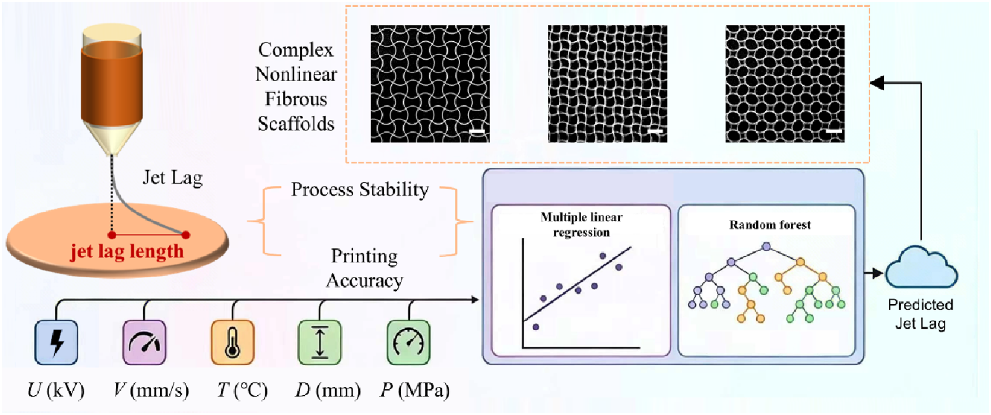
2. Experimental section
2.1. Material preparation
PCL (Mw = 50 kDa, Capa® 6500, Perstorp AB) pellets were sourced from Dongguan KXL Plastic Raw Material Co., Ltd. Prior to experimental use, the PCL pellets were loaded into a custom alumina syringe (Guangdong Blue Whale Ceramic Technology Co., Ltd.) and subjected to vacuum drying at 90 °C for 12 hours to remove residual moisture and eliminate entrapped air. Following this treatment, the syringe was equilibrated to room temperature (23.5±1 °C) and stored in a desiccator to minimize moisture uptake. For each printing experiment, the syringe was thermally conditioned within the MEW system at 90 °C for 30 minutes to attain a uniform molten phase with desired fluidity. All procedures were carried out in a controlled environment (temperature: 23.5±1 °C, relative humidity: 35±5%) to ensure process repeatability. After each printing, residual PCL was retained in the syringe and stored in a desiccator for subsequent experiments.
2.2. MEW system configuration
The MEW system comprised four functionally integrated units, as depicted in Figure 2: (a) Material feeding: A customized 5-mL alumina ceramic syringe was loaded with molten PCL and fitted with a 24-gauge stainless steel nozzle (inner diameter: 0.27 mm). The syringe’s upper port was linked to an air compressor (Hong Run Compressor Technology Co., Ltd.) via a pressure regulator (0–0.4 MPa range) to ensure controlled extrusion. (b) Thermal regulation: A dual-layer heating assembly enclosed the syringe, with a PID-controlled heating pad placed between the ceramic walls to maintain temperature control. (c) High-voltage generation: A high-voltage DC power supply (Teslaman Technology Co., Ltd.) provided an adjustable electric field (0–20 kV range), where the nozzle is connected to the positive terminal and a circular copper collector plate (150 mm diameter × 0.5 mm thickness) to the negative terminal. The nozzle-to-collector distance was fixed at 7 mm using a Z-axis slide (Suzhou Zhide Automation Co., Ltd.). (d) Motion control: The collector plate, mounted on a polylactic acid (PLA)-insulated base, was driven by a computer-controlled XY translational stage (Suzhou Zhide Automation Co., Ltd.) with a positional resolution of 1 μm, enabling programmable movements. Schematic illustration of the MEW system configuration. The system comprises four integrated functional units: (a) Material feeding, (b) Thermal regulation, (c) High-voltage generation and (d) Motion control.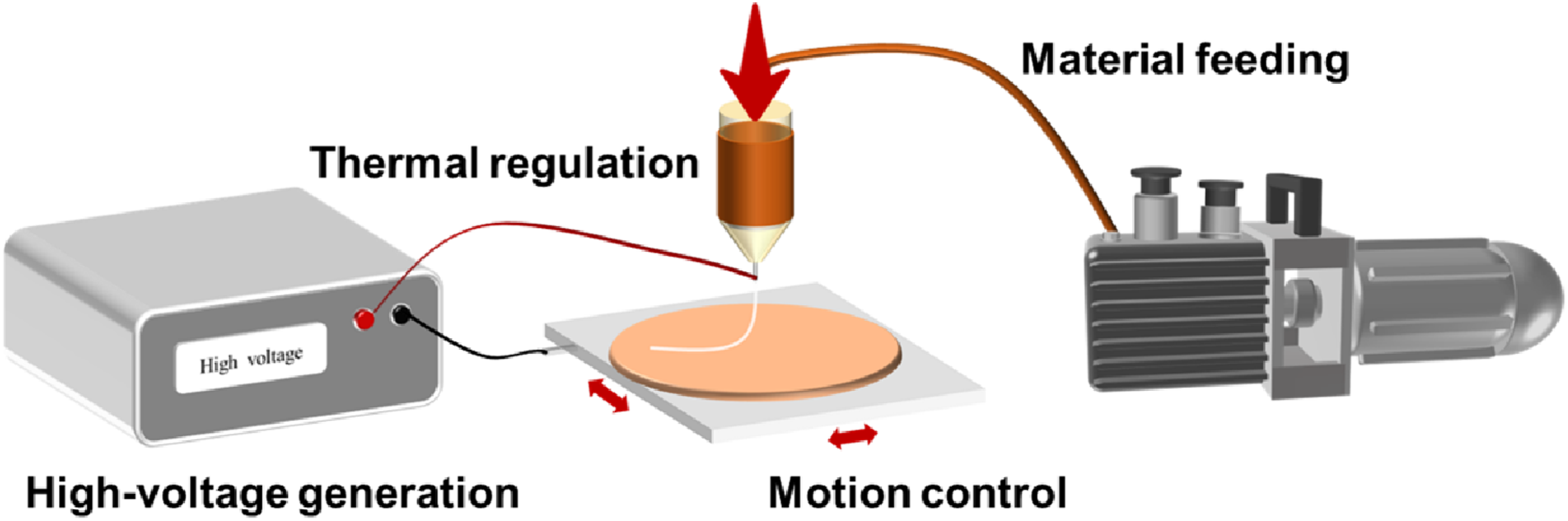
2.3. Image acquisition and toolpath design
To systematically capture jet images under varying process parameters, an industrial camera (MIchrome 20, Shenzhen SANOTID Optical Instrument Co., Ltd.) was fixed at a position aligned horizontally with the nozzle, ensuring a clear view of the nozzle and jet at the same angle and distance. Illumination was provided by an LED light panel positioned behind the collector to enhance the contrast of the jet (Figure 3(a)). For each combination of process parameters, 50 images were acquired to ensure that enough clear and stable jet images were available for subsequent analysis and computation and to reduce the influence of incomplete or low-quality images. Additionally, the printed samples were imaged using a scanning electron microscope (KYKY-EM6200, KYKY Technology Co., Ltd.). Schematic illustration of the jet image acquisition setup and toolpath design. (a) The industrial camera is aligned horizontally with the nozzle, and an LED light panel is placed behind the collector. (b) Reciprocating toolpaths along the X-axis ensure the platform moves parallel to the focal plane of the camera.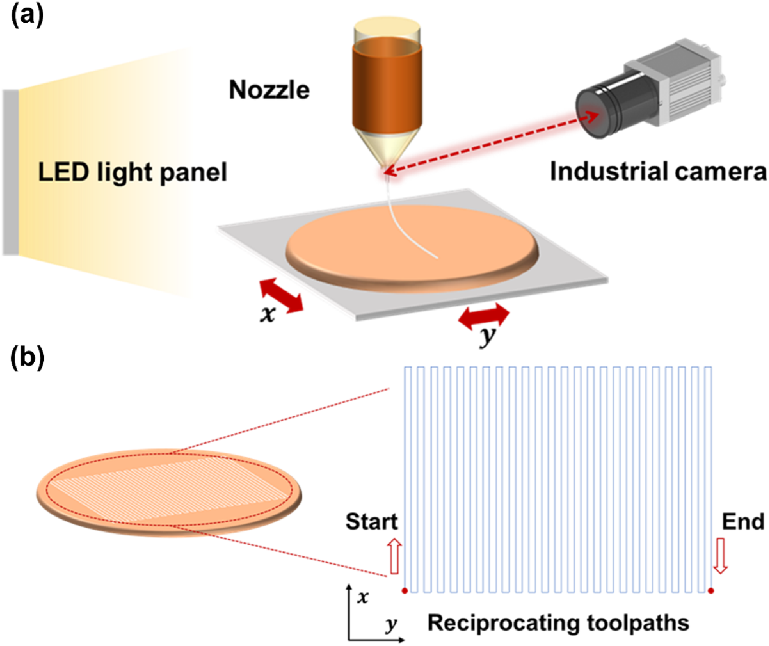
To ensure accurate measurement of the jet lag length from the captured images, reciprocating toolpaths along the X-axis were designed and programmed (with minimal offset in the Y-axis direction). These toolpaths ensured that the platform moved parallel to the camera’s focal plane, allowing the camera to continuously and fully capture the jet lag with acceptable clarity (Figure 3(b)). Each segment exceeded 50 mm in length, with a minimum printing duration of 5 seconds, ensuring that a steady-state jet was captured for analysis.
2.4 Image processing algorithm for jet lag length computation
Raw images captured by the industrial camera were first converted to grayscale to facilitate feature extraction. An adaptive thresholding method was applied to binarize the images. In the binarized image, the contours of the objects in the image can be identified, sequentially representing the nozzle, jet, and collector from top to bottom. (Figure 4(a)). Image processing workflow for computing jet lag length. (a) Image preprocessing steps including gray scaling, binarization and contour extraction. (b) Schematic illustration of the contour extraction processing steps and jet lag length computation.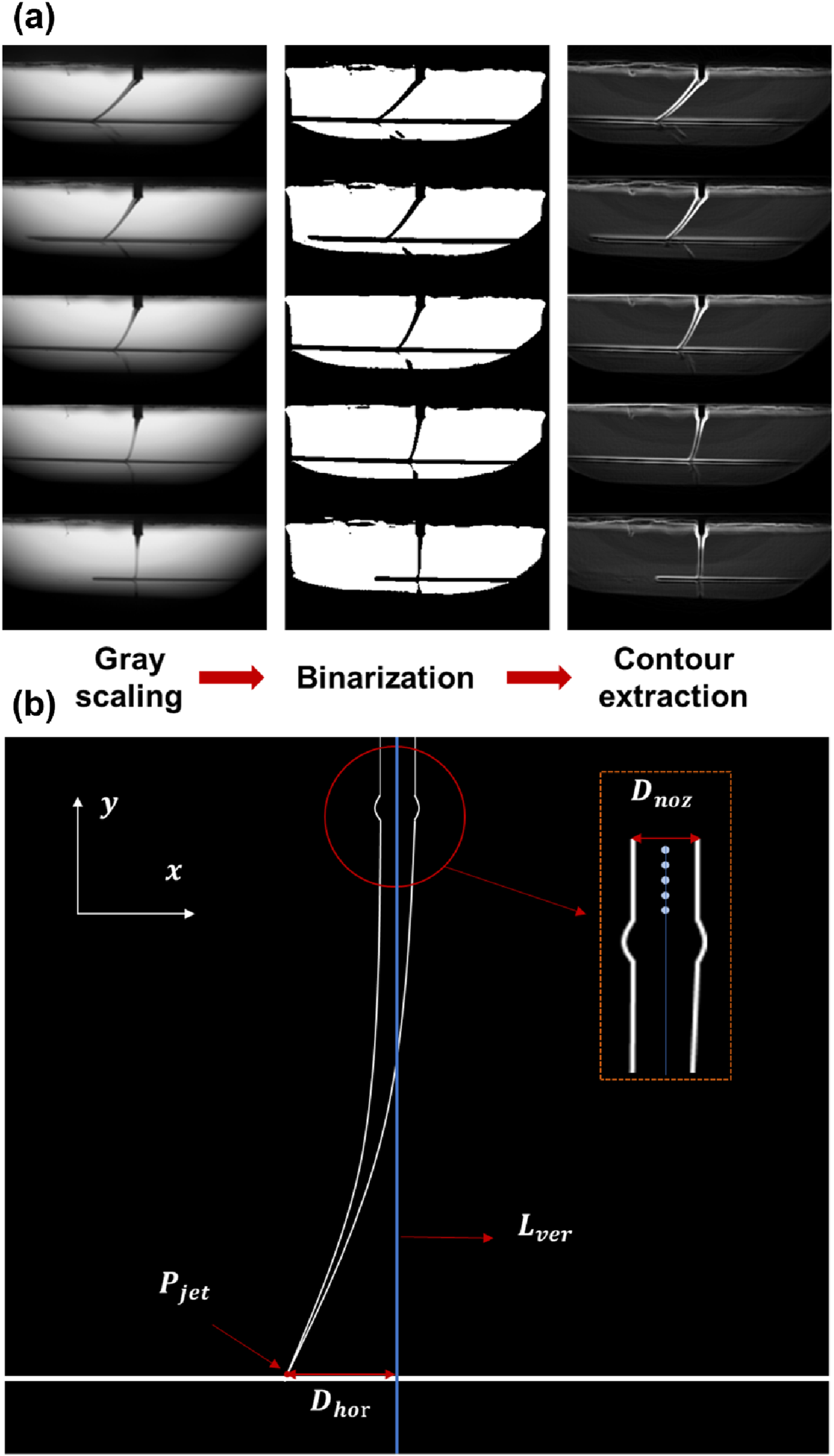
Based on the extracted contours, the jet lag length can be calculated as follows. First, the pixels are scanned from left to right for each row for the index of the first white pixel. When this index keeps invariant for five consecutive rows, it is identified as the location of the left edge of the nozzle. The horizontal distance between the first and last white pixels in these rows defines the outer diameter of the nozzle (
The midpoints between these edge pixels are calculated for each row, and connected to form a vertical reference line (
Subsequently, scanning resumes downward from the nozzle edge until the index of the first white pixel starts to change, which indicates the uppermost location of the jet.
Scanning continues until a row exceeds a predefined jet diameter threshold (
Finally, the horizontal offset between

2.5 Single-factor experiments
Parameter ranges and reference levels for single-factor experiments.

2.6 Data processing
For each combination of parameters, 10 representative images were selected from the 50 acquired images for quantitative measurement, and the results are expressed as the mean ± standard deviation. As shown in Table 1, data collection was performed for 6 levels of each parameter while the remaining parameters were kept at their reference levels, resulting in a total of 300 data points (6 levels × 5 parameters × 10 images). This dataset was designed as a controlled first-step dataset for jet lag prediction, with emphasis on physically interpretable single-factor trends rather than full coverage of the multidimensional parameter space. The statistical significance between process parameter levels was assessed using one-way analysis of variance (ANOVA) followed by Tukey’s post hoc test (α=0.05). Group differences were annotated in figures using lowercase letters, where distinct letters denote statistically significant deviations (p<0.05).
2.7 Model development and performance evaluation
To evaluate the effects of process parameters on the jet lag length and to develop predictive models, two supervised learning models were employed: multiple linear regression and random forest. Multiple linear regression was used as an interpretable baseline model to show the first-order effects of the five process parameters on the jet lag length, whereas random forest was used as a more flexible model to account for potential nonlinear dependencies in the dataset. In this way, the comparison between the two models allowed both interpretability and predictive performance to be considered.
Explicit interaction and quadratic terms were not included in the present multiple linear regression model. This is because the current dataset was mainly generated from single-factor experiments, which are suitable for identifying first-order trends but do not fully cover the multidimensional parameter space needed to robustly estimate higher-order terms. In addition, including such terms would substantially increase model complexity and could lead to unstable coefficients under the current dataset structure. Therefore, a relatively simple multiple linear regression model was used as the baseline model in this study.
Prior to model development, the dataset was assessed for suitability. The dataset was then randomly divided into a training set (80%) and a test set (20%), using a fixed random seed (42) for reproducibility. Because the data were collected under a controlled single-system experimental setting rather than across clearly separable experimental batches, no batch grouping was applied. The training set was used for model fitting, and the test set was used for model evaluation. Model performance was assessed using the coefficient of determination (R2), root mean square error (RMSE), and mean absolute error (MAE). Given the modest dataset size and the structured single-factor design, the predictive results should be interpreted within the scope of the present dataset.
3. Results and discussion
3.1 Single-factor experimental analysis of process parameters on jet lag length
In the single-factor experimental analysis, we investigated the individual effects of five key process parameters on the jet lag length: material temperature, collector speed, nozzle-to-collector distance, voltage, and air pressure. These process parameters were chosen due to their ease of dynamic control during experiments and their significant effects on jet lag based on our previous attempts. Other potential process parameters, such as the thermal conductivity, viscosity, density, relative permittivity, and electrical conductivity of PCL, as well as nozzle inner diameter and ambient temperature and humidity, were not considered.
The corresponding single-factor results are shown in Figure 5. Overall, Figure 5 shows clear correlations between jet lag length and each parameter. Specifically, jet lag length decreases with increasing material temperature and voltage, indicating negative correlations, whereas it increases with increasing collector speed, nozzle-to-collector distance and air pressure, indicating positive correlations. These trends provide the basis for the following mechanistic interpretation. Independent effects of process parameters on the jet lag length (L). (a), (b), (c), (d) and (e) show the effects of material temperature (T), collector speed (V), nozzle-to-collector distance (D), voltage (U) and air pressure (P) on the jet lag length, respectively. Overall, jet lag length decreases with increasing material temperature and voltage, but increases with increasing collector speed, nozzle-to-collector distance, and air pressure.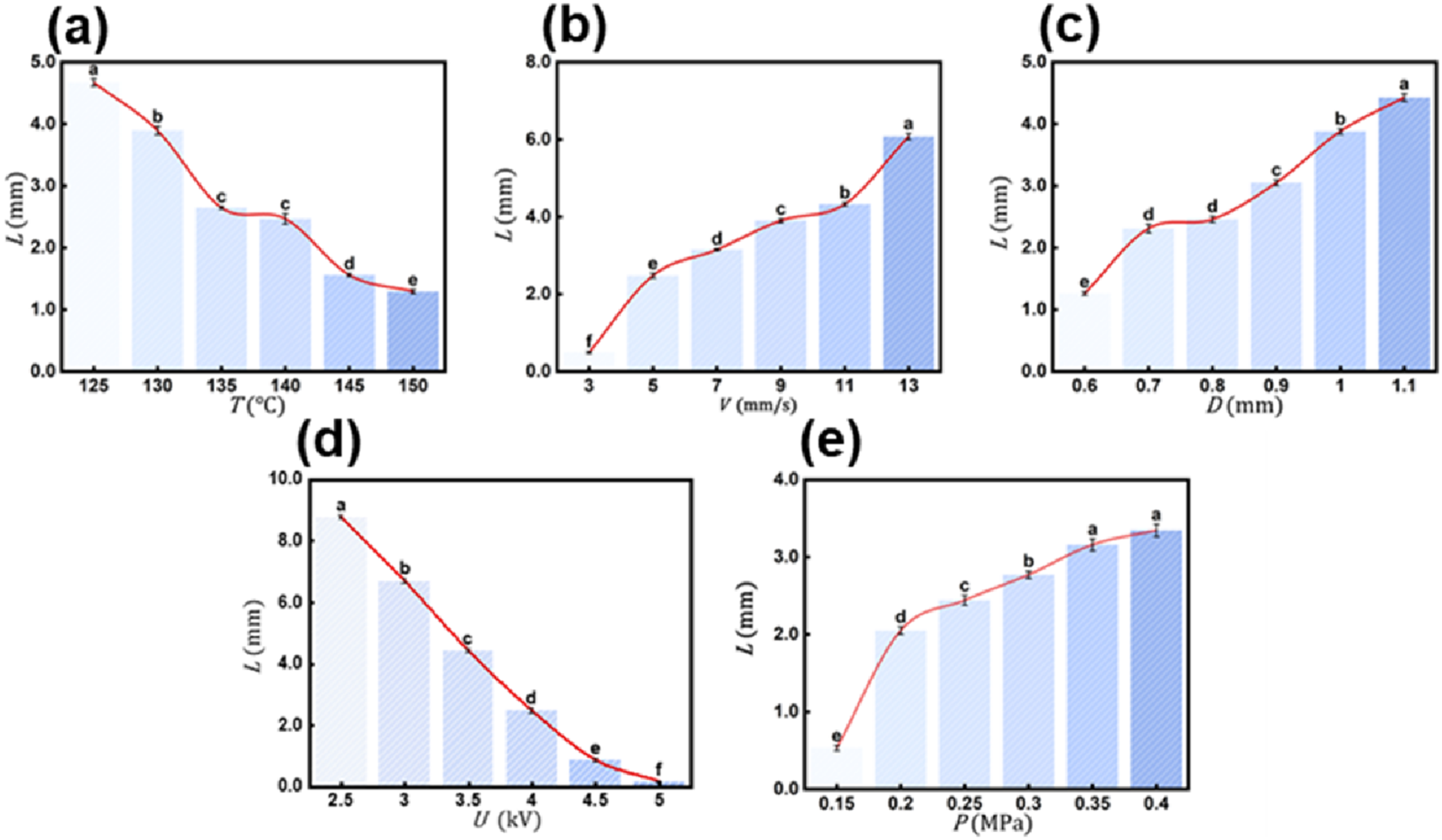
These results are consistent with the fundamental principles of the MEW process. During MEW, the high voltage at the nozzle injects positive charges into the melt through two mechanisms: field emission and charge dissociation, forming the physical basis for the electrostatic stretching of the jet. The viscoelastic resistance opposing this stretching primarily stems from the viscosity of the melt, which decreases with higher material temperature. This reduction in viscosity allows for faster jet acceleration and results in a smaller jet lag length (Figure 5(a)). An increase in collector speed elevates the mechanical drag on the jet, causing it to deviate more from the nozzle’s projection on the collector and thus increasing jet lag length (Figure 5(b)). Nozzle-to-collector distance affects the electric field intensity. When voltage is fixed, increasing nozzle-to-collector distance weakens the electric field, slowing jet deposition and increasing jet lag length (Figure 5(c)). Higher voltage increases both charge density and electric field intensity. The greater electrostatic force accelerates jet deposition, thereby reducing jet lag length (Figure 5(d)). Lastly, air pressure influences the melt flow rate. Higher air pressure boosts the flow rate. Under the same electric field conditions, this reduces the charge density per unit mass of the melt, diminishing the electrostatic force per unit mass and leading to a larger jet lag length (Figure 5(e)).
3.2 Model selection for multiple linear regression and random forest
As described in Section 2.7, multiple linear regression and random forest were employed as complementary models to evaluate both first-order trends and potential nonlinearities.
For the multiple linear regression model, the main assumptions, including linearity, residual normality, homoscedasticity, independence of observations, and absence of multicollinearity, were checked before further analysis. The detailed results are provided in the Supporting Information (Figure S1 and Table S1). Compared with multiple linear regression, random forest requires fewer assumptions about data distribution and is more flexible in handling potentially complex relationships. Therefore, multiple linear regression and random forest were used here as complementary models for comparing interpretability and predictive capability in jet lag prediction.
3.3 Qualitative comparison of feature importance rankings between multiple linear regression and random forest
Understanding how different process parameters influence jet lag length is important for both model interpretation and process optimization. In the multiple linear regression model, the standardized coefficients (β) were used to indicate the linear contribution of each process parameter to jet lag length. For a given parameter, β was calculated using Equation (2)

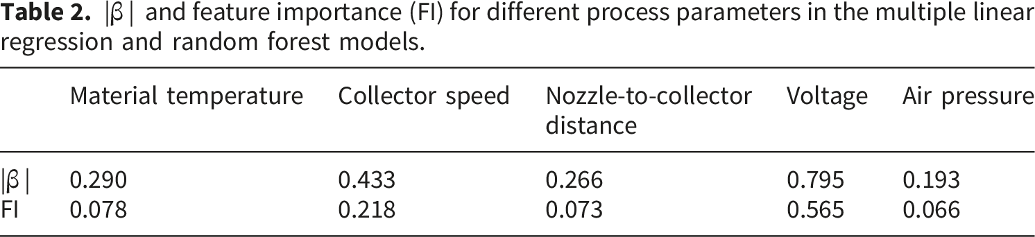
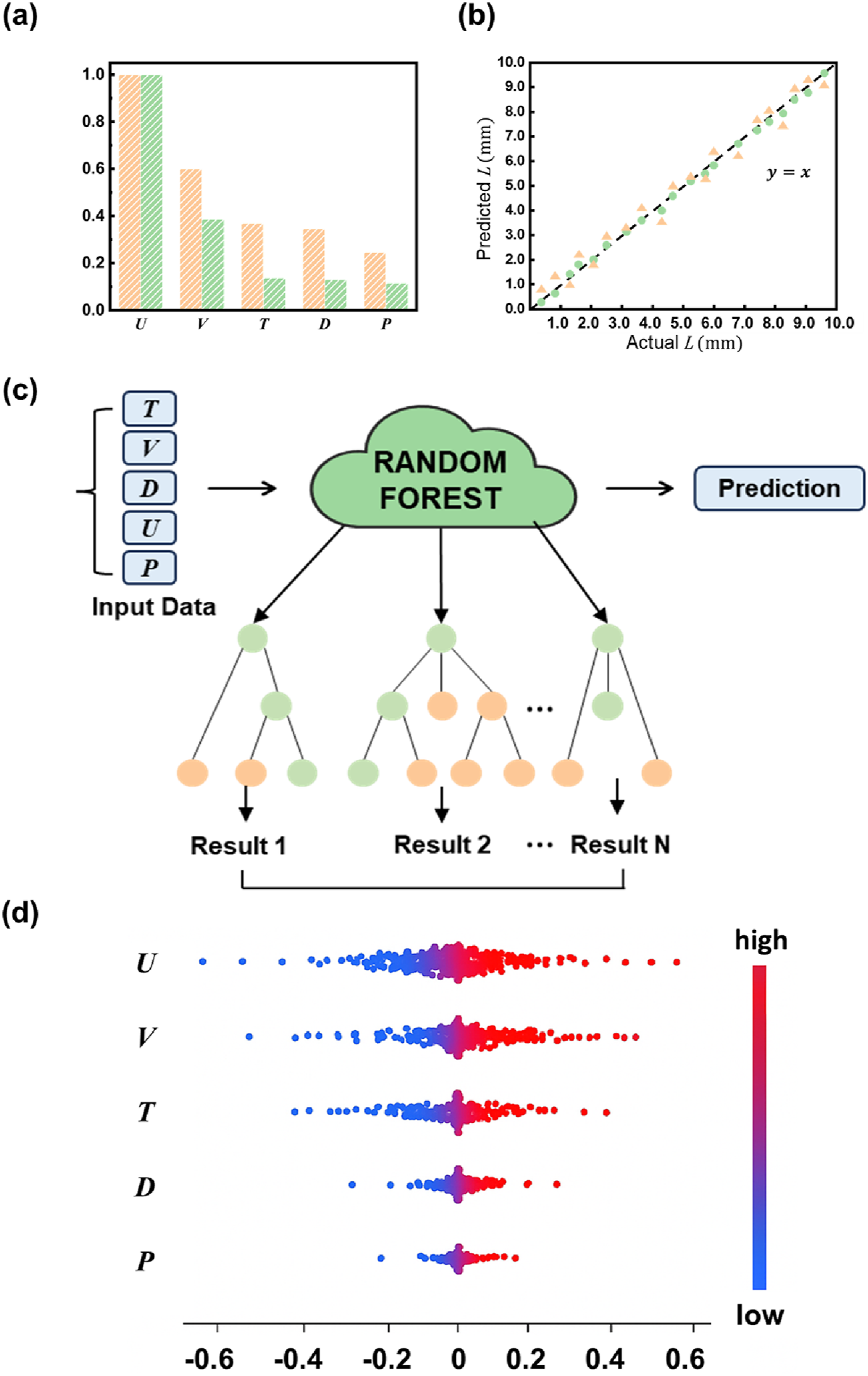
On the other hand, random forest assesses feature importance through the mean decrease in impurity denoted by FI, which quantifies how much a feature contributes to reducing prediction uncertainty. For a specific parameter, FI can be calculated using Equation (4): Comparison of feature importance rankings, predictive performance, and model interpretability. (a) Feature importance rankings identified by the multiple linear regression and random forest models, shown as orange and green bars, respectively. (b) Comparison of predicted and actual jet lag length values on the test set using 20 randomly selected data points, where orange triangles and green circles denote the multiple linear regression and random forest models, respectively. (c) Schematic diagram of the random forest model. (d) Distribution of Shapley additive explanations (SHAP) values for each feature in the random forest model. The color gradient from blue to red indicates low to high feature values. In Figure 6, U, V, T, D, and P denote voltage, collector speed, material temperature, nozzle-to-collector distance, and air pressure, respectively.
3.4 Comparison of predictive performance and practical implications of multiple linear regression and random forest
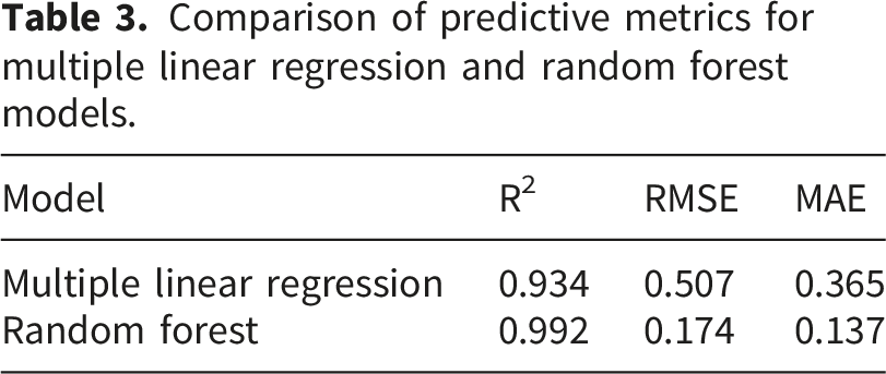
Comparison of predictive metrics for multiple linear regression and random forest models.
Random forest is an ensemble learning method based on decision trees, as schematically illustrated in Figure 6(c). Compared with multiple linear regression, random forest is better suited to representing potential nonlinear dependencies within the current dataset, whereas multiple linear regression is restricted to first-order linear effects. This distinction is relevant because the MEW process is governed by multiple physical mechanisms, including extrusion, electrostatic stretching, and solidification, which may give rise to nonlinear dependencies among process parameters. However, this result should be interpreted with appropriate caution. The present findings should not be regarded as definitive evidence of multidimensional interaction learning, because the current dataset was mainly generated from single-factor experiments and does not fully cover the coupled parameter space of MEW. Stronger validation of such effects will require future experiments involving deliberately coupled multi-parameter conditions or testing under previously untested parameter combinations.
From an interpretability perspective, multiple linear regression provides clear information on the direction and relative magnitude of first-order parameter effects, which is useful for understanding how individual process parameters relate to jet lag length. Random forest, in contrast, offers greater flexibility in prediction but requires additional tools for interpretation. Therefore, SHAP values were used to interpret the random forest model internally. As shown in Figure 6(d), SHAP values quantify the direction and magnitude of each feature’s contribution to the random forest prediction of jet lag length. Values on the right side of zero contribute to a higher predicted jet lag length, whereas values on the left side contribute to a lower predicted jet lag length. The wider spread observed for voltage, collector speed, and material temperature suggests that these features exert relatively stronger effects on the prediction, while nozzle-to-collector distance and air pressure play comparatively smaller roles.
From a practical perspective, the comparison between multiple linear regression and random forest suggests different use scenarios for the two models in MEW. Multiple linear regression is useful when interpretable first-order parameter trends are of primary interest, whereas random forest is more suitable when accurate jet lag prediction is needed to support nonlinear printing. Therefore, the value of random forest in this study lies not only in its higher predictive accuracy, but also in its practical utility for improving printing accuracy in MEW.
3.5 Experimental validation of the predictive framework
To further evaluate the practical usefulness of the predictive framework, nonlinear printing was implemented with the circle curve used as the toolpath. As reported in our previous research, if the jet lag length is kept constant and the printed fiber pattern is a circle, the toolpath will be a concentric circle with a larger radius. To be specific, the radius of the fiber pattern (r) and the toolpath (R) follow Validation of predictive accuracy of random forest model by printing circular fiber pattern. (a) Relationship between r and R, which represent the radii of the fiber pattern and the toolpath, respectively. (b) and (c) show the calculated and actual printed fiber patterns when jet lag length (L) varies from 1 to 5 mm while R is fixed at 6 mm. (d) Comparison of actual r with calculated r, showing high consistency across different jet lag length values.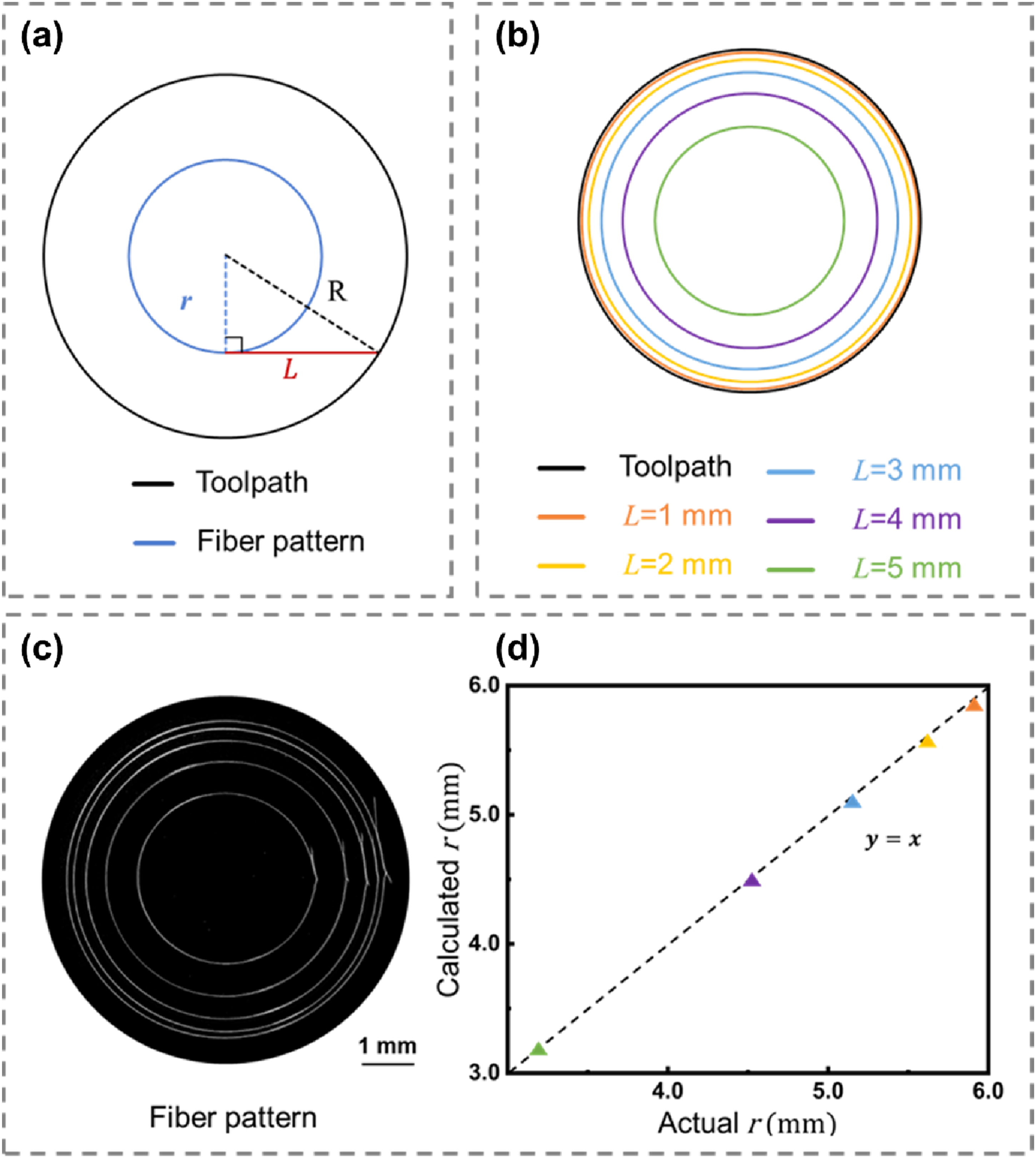
3.6 Printing of complex nonlinear fibrous scaffolds and the limitation of residual charge effects
Building upon the validated predictive performance, we further applied the jet lag prediction to the fabrication of complex nonlinear fibrous scaffolds. As shown in Figure 8, by adjusting process parameters based on the predicted jet lag length, the resulting fibrous scaffolds exhibit well-ordered fiber stacking and high accuracy, highlighting the positive impact of jet lag prediction on both printing stability and accuracy. SEM images of complex nonlinear fibrous scaffolds printed using process parameters optimized based on the predicted jet lag. (a2-c2) and (a3-b3) are locally magnified SEM images of (a1-c1), respectively. Scale bars: 200 μm (a1-c1), 100 μm (a2-c2), 50 μm (a3-c3).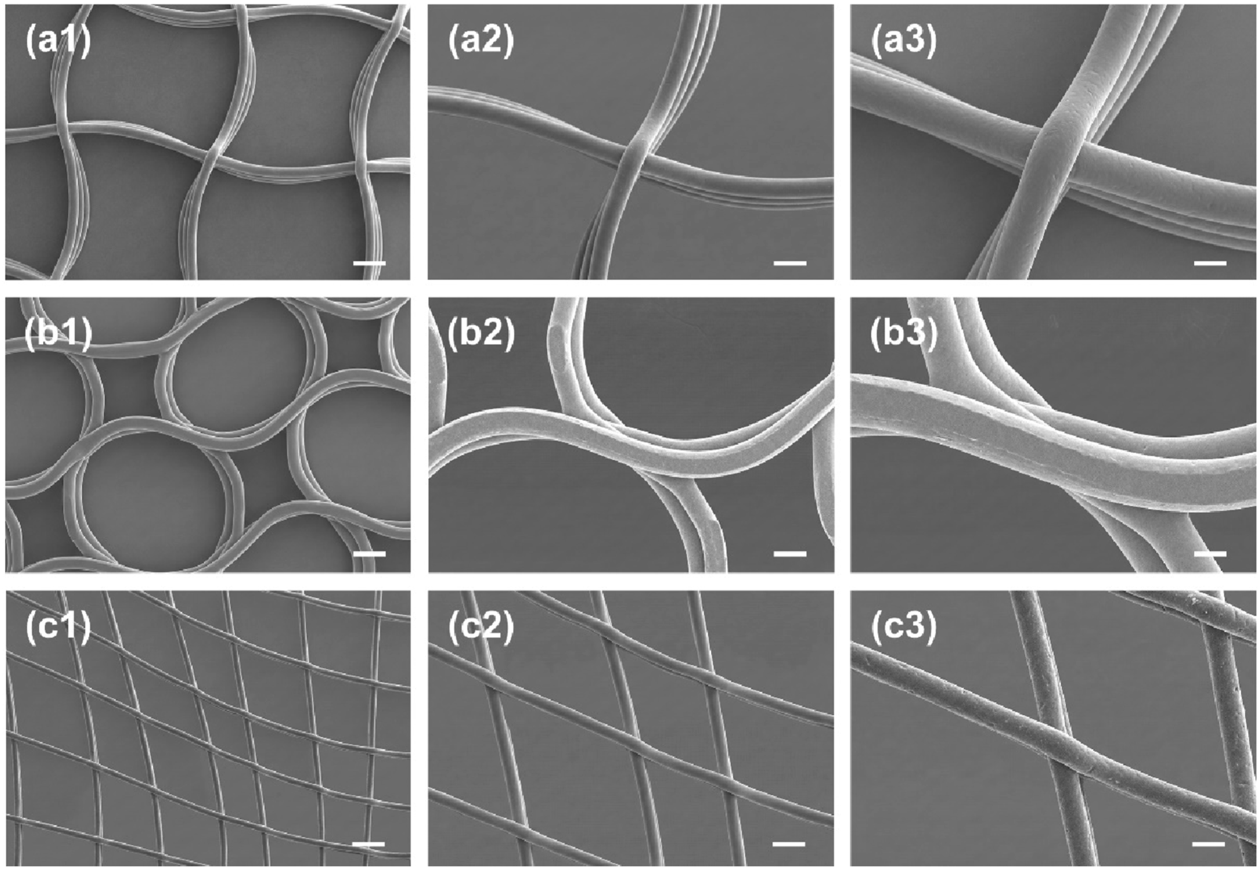
However, we observed a phenomenon where the jet lag length tended to increase as printing progressed to higher layers, even with unchanged process parameters. This is attributed to the gradual accumulation of positive charges injected into the polymer on the collector. This accumulation creates repulsion with the similarly positively charged jet, weakening the electric field’s acceleration effect on the jet and thereby increasing the jet lag length. It should be noted that the current predictive models were trained using data collected under single-factor, effectively low-layer printing conditions. Therefore, although the models show high predictive accuracy under the present conditions, their performance may decrease in higher-layer printing, where residual charge effects become more pronounced. Addressing this dynamic influence of residual charge remains an important challenge for future model development and for more accurate prediction in complex MEW fabrication.
4. Conclusion
Jet lag is a key process variable in MEW because it directly affects both process stability and printing accuracy. In this study, a machine-learning-assisted framework was established for jet lag prediction in MEW using five process parameters: material temperature, collector speed, nozzle-to-collector distance, voltage, and air pressure. Multiple linear regression and random forest were comparatively evaluated, showing that both models were able to predict jet lag length effectively, while random forest achieved better predictive performance under the present dataset.
The comparison between the two models also highlights their different roles. Multiple linear regression provides interpretable first-order information on how the process parameters relate to jet lag length, whereas random forest offers greater flexibility for prediction within the current dataset. Experimental validation further showed that the predicted jet lag values could successfully guide nonlinear printing and the fabrication of complex nonlinear fibrous scaffolds, demonstrating the practical value of the framework for improving printing accuracy in MEW.
At the same time, the present study has several limitations. The dataset was mainly generated from single-factor experiments and therefore represents a controlled first-step dataset rather than full coverage of the multidimensional parameter space of MEW. In addition, the current predictive models may be less effective in higher-layer printing, where residual charge accumulation becomes more important. Future work should therefore include coupled multi-parameter experiments, validation under previously untested parameter combinations, and model development that accounts for the dynamic influence of residual charge during printing.
Supplemental material
Supplemental material - Machine learning-aided jet lag prediction for high-accuracy fabrication of melt electrowriting fibrous scaffolds
Supplemental material for Machine learning-aided jet lag prediction for high-accuracy fabrication of melt electrowriting fibrous scaffolds by Yunpeng Wang, Yi He, Anni Wang, Wenjie Xu, Hongnan Zhang in Journal of Industrial Textiles
Footnotes
Funding
The authors disclosed receipt of the following financial support for the research, authorship, and/or publication of this article: This work was supported by “the Fundamental Research Funds for the Central Universities” [CUSF-DH-T-2025084].
Declaration of conflicting interests
The authors declared no potential conflicts of interest with respect to the research, authorship, and/or publication of this article.
Data Availability Statement
The data that support the findings of this study are available from the corresponding author upon reasonable request.
Supplemental material
Supplemental material for this article is available online.
References
Supplementary Material
Please find the following supplemental material available below.
For Open Access articles published under a Creative Commons License, all supplemental material carries the same license as the article it is associated with.
For non-Open Access articles published, all supplemental material carries a non-exclusive license, and permission requests for re-use of supplemental material or any part of supplemental material shall be sent directly to the copyright owner as specified in the copyright notice associated with the article.