
Abstract
Entrapment of a central venous catheter (CVC) guide wire in an inferior vena cava (IVC) filter is a rare, but reported complication during CVC placement. With the increasing use of IVC filters, this number will most likely continue to grow. The consequences of this complication can be serious, as continued traction upon the guide wire may result in filter dislodgement and migration, filter fracture, or injury to the IVC. In this article, we review the various preferred techniques reported in the literature for removal of the entrapped guide wire in particular situations, along with their indications, advantages, and disadvantages. We present simple useful recommendations to prevent this complication.
Keywords
Introduction
Inferior vena cava (IVC) filters were initially used in 1967 for prevention of pulmonary embolism. 1,2 Some authors advocate the routine prophylactic placement of filters in high-risk patients to decrease pulmonary embolic complications. 1,3 –6 Based on this increased use of filters, it is estimated that approximately 20 000 to 30 000 filters are placed annually in the United States. 1,2 With the increasing widespread acceptance of retrievable IVC filters, this number will most likely continue to grow.
Similarly, percutaneous placement of central venous catheter (CVC) over the wire without fluoroscopic guidance has become a routine bedside procedure especially with the increased availability of bedside portable ultrasound devices. 7 –11 Although this approach is safe in most cases, several authors have reported entrapment of J-tipped guide wires in previously placed IVC filters with subsequent filter fracture, filter dislodgment and migration, filter tilting, wire breakage, or inability to remove the wire from the filter. 2,7,12 –25 Vigorous attempts to free entrapped guide wires could also lead to vena cava rupture, particularly if the filter has been incorporated into the IVC wall. 20 With the increased use of IVC filters and increased placement of bedside CVC without fluoroscopic guidance, the incidence of this complication is likely to increase mandating heightened awareness by physicians and interventional radiologists on how to prevent and how to manage this complication.
Several endovascular techniques have been used to remove entrapped guide wires successfully without causing filter migration or filter fracture and fragmentation, or clinically significant trauma to the IVC. The use of each technique depends on several factors including the accessibility of the J tip of the entrapped wire, the point of entrapment in the IVC filter, the location of the access site, the length of wire protruding from the access site, and the accessibility of the femoral veins. We will review the various techniques reported in the literature for removing entrapped guide wires along with their indications, advantages, and disadvantages of each technique. We will outline the preferred technique in particular situations. We will also present simple useful recommendations to prevent this complication.
Review of Published Entrapped Guide Wire Dislodgement Techniques
Percutaneous placement of IVC filters has gained popularity as an acceptable means of preventing pulmonary embolism. 7 Patients requiring prophylactic IVC filters are typically ill or at high risk, mandating prolonged intensive care unit observation. These patients often require multiple CVC or pulmonary artery catheters, placing them at greater risk of guide wire entrapment. 1 Although, the in vivo incident of guide wire entrapment is unknown, in our own experience, it does not appear to be very common. However, once a guide wire is entrapped the clinician should know how to handle such a mishap. Forceful withdrawal is absolutely contraindicated. Aggressive manipulation could result in serious injury to the IVC wall. In addition, filter dislodgement, migration, and fracture may occur and the damaged or displaced filter or its fragments can migrate to the heart or pulmonary arteries, potentially causing injury to those structures, or cause cardiac dysrhythmia. Multiple case reports have been published that describe these complications. 2,7,12 –28
The frequency of this complication is similar for both newly inserted CVC and replacements using the same site, suggesting that changing a CVC over a guide wire is no safer than placing a new one. 26 The potential for contact between a guide wire and IVC filter exists whenever a CVC is placed since these wires can easily reach well into the IVC, passing between the legs of the filter, and the wire might become entrapped during removal. With the currently available filters in the market, entrapment is likely to occur in the narrow space between the filter’s legs. 2,29
The risk of contact between a wire and a filter, and thus the risk of entrapment, is increased when the distance between the venous access site and the filter is reduced. This may be the case in patients with short stature, when right jugular or subclavian approaches are used, or when the filter is in a suprarenal location. 30 Similarly, the risk increases when longer guide wires are introduced. 2 Although a femoral vein approach places the CVC insertion site in close proximity to an IVC filter, to our knowledge, there have been no reports in the literature of entrapment from a femoral approach.
Kaufman and colleagues 29 and Stavropoulos and colleagues 31 evaluated guide wire engagement, disengagement, and entrapment with a variety of permanent IVC filters in an in vitro model. Wire “engagement” was defined as change in shape or a sensation of resistance during passage of the wire through the filter. Wire “disengagement” was defined as separation of the guide wire and the filter without damage to either device during the application of continued traction to the guide wire. Wire “entrapment” was defined as the inability to separate the guide wire and filter without causing structural damage to either the wire or the filter. They reported guide wire engagement in all filters tested with 15-, 3-, and 1.5-mm J-tipped wires. The straight wire did not engage any of the filters. They demonstrated an increase in guide wire engagements with increasing guide wire diameter and that the 15-mm J-tipped wire engaged the filters more often than the other wires but never became entrapped in a filter. The TrapEase filter (Cordis Endovascular/Johnson & Johnson, Warren, New Jersey), the stainless-steel Greenfield filter (Medi-tech, Watertown, Massachusetts), and the Vena Tech LGM filter (B Braun Vena Tech, Evanston, Illinois) entrapped the 3- and 1.5-mm J wires. They noticed that all entrapments occurred from the jugular approach and none from the femoral approach.
In 2005, Rosen and colleagues 1 investigated engagement and entrapment of 0.032 and 0.035 in, 60 cm, J-tipped guide wires that are available in CVC kits (Arrow International, Reading, Pennsylvania) with 4 types of filters inserted into an in vitro flow model. The 4 filters studied were OptEase (Cordis Endovascular/Johnson & Johnson), Günther Tulip (Cook, Bloomington, Indiana), Vena Tech LP (B Braun Vena Tech, Evanston, Illinois), and Recovery (CR Bard, Covington, Georgia). The 0.032 in guide wire resulted in a lower incidence of entrapment and filter migration for all filters (0%, 7.5%, respectively) compared to the 0.035 in guide wire (1%, 26.5%, respectively). They reported that the smaller diameter guide wire resulted in a decreased incidence of adverse events for all the filters, but there is still risk of complications. 1
Therefore, it is obvious that the reasons for guide wire entrapment is related to both guide wire and filter design. 29,31 Small diameter J-tipped wires such as the 1.5- and 3 mm J-tipped guide wires are prone to entrapment, whereas 15 mm J wires and straight wires are less likely to become entrapped. This relates to the relative inability of the small diameter J-shaped portions of the wires to release from a filter when they are engaged. 29,31 The typical design of most general-purpose 3-mm J-tipped guide wires, including those supplied with CVC kits, consists of an outer wire coil and an inner mandrel and safety wire. 31 It is possible that the use of a wire with smooth outer surface (such as hydrophilic coated wire) might decrease the rate of guide wire entrapment, but these wires are not typically available in standard CVC kit and they have other potential complications such as passing easily into side branches and causing perforations. 1,31 Certain filter designs are more susceptible to guide wire entrapment. Filters with an open hole at the apex of the filter such as the TrapEase, Vena Tech LGM, and stainless-steel Greenfield filters are more likely to entrap wires. The distance between each of the limbs at their origin from the apex of the filter also appears to have a role in wire entrapment. The TrapEase, stainless-steel Greenfield, and Vena Tech LGM filters have larger spaces between the origins of the limbs than the other filters allowing entrapment of guide wires. 31 Fortunately, the stainless-steel Greenfield filter is no longer available in the market, and the other 2 filters are not commonly used by most operators.
Whenever unexpected resistance is encountered while attempting to remove a guide wire from the central venous circulation in a patient with an IVC filter, the operator should stop pulling immediately and force should never be used. 25,26,29 In case of internal jugular or subclavian venous access, force directed in a cephalic fashion would be expected only to either make the entrapment worse or increase the chance of filter displacement, filter fracture, and other complications. 25,26 When entrapment is recognized, the patient should be brought to an interventional suite, where manipulations can be done under fluoroscopic guidance to disengage the wire from the filter. 31 Interventional techniques under fluoroscopic guidance are highly successful in disengaging the wire without damage to IVC filter or traumatizing the IVC. When IVC filters are displaced or fractured, the success rate is lower and associated with worse outcomes. Even caudal displacement could cause the IVC filter to tilt enough to be ineffective in trapping emboli. 26
Multiple case reports in the literature describe various techniques for percutaneous removal of guide wires entrapped in the IVC filters. Femoral snare technique: if the tip of the entrapped wire is accessible, a goose neck snare can be used to free it. The snare is inserted from a femoral approach, and is used to grasp the exposed guide wire tip. The guide wire is then pulled down through the filter and removed via the femoral vein (Figure 1A). If any resistance is encountered, or the filter begins to move, a long sheath or guide catheter should be advanced over the snare device to brace the filter as the guide wire is removed (Figure 1B).
2
Angiographic catheter-directed technique: this technique can be used when the tip of the entrapped wire is not accessible and cannot be snared. Among these techniques is advancing a 5- or 6-F angiographic catheter over the entrapped guide wire and using the catheter to push the guide wire away from the point of entrapment (Figure 2A). After the wire is free, any residual curve at the guide wire tip should be straightened with the catheter to prevent reengagement (Figure 2B). This technique is usually successful in most cases.
2,32
Andrews and colleagues
2
reported their use of this technique to free a J-tipped guide wire entrapped in a 12-F stainless steel Greenfield filter. Monorail technique: if the tip of the entrapped guide wire is inaccessible and there is only a short length of guide wire protruding from the access site in the internal jugular or subclavian vein such that a catheter cannot be advanced over it, a monorail system can be created by cutting a small hole in the distal end of a catheter, a guiding catheter, or an introducer of a long sheath. Wholey and colleagues
33
described a technique for removal of entrapped guide wire inserted through right internal jugular vein access by creating a small hole in the introducer of a 7-F long vascular sheath to create a monorail system. Abdel Aal and colleagues
34
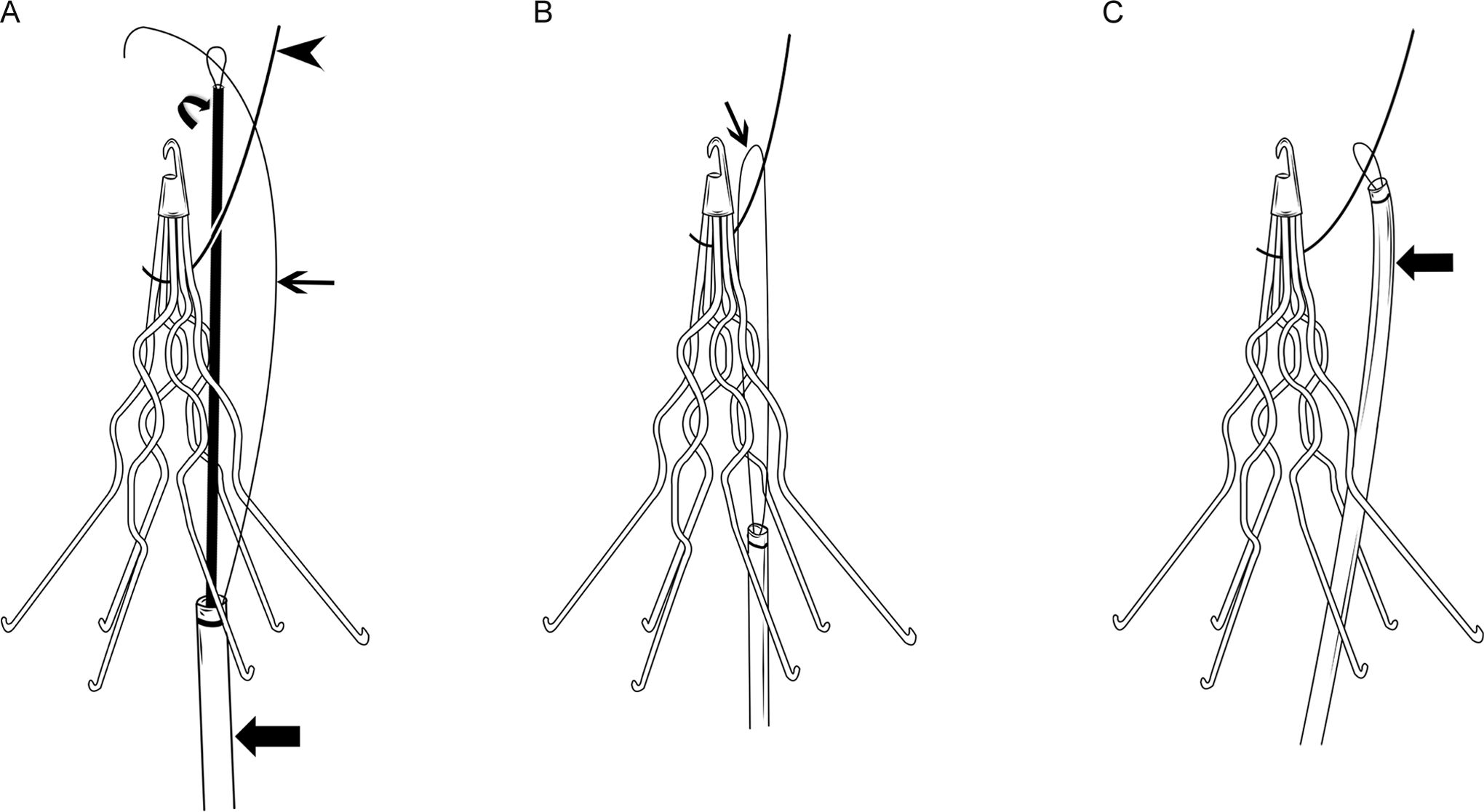
described a monorail technique for freeing an entrapped guide wire inserted through left subclavian access by creating a hole in a guiding catheter (Figure 3). The authors recommended creating a hole in a less stiff guiding catheter to negotiate through tortuous anatomy (Figure 3A), then placing a stiff wire in the guiding catheter when caudal force is required to either advance the catheter in the IVC or free the entrapped wire (Figure 3B and C). This latter technique is more optimum than using the stiff introducer of a long sheath which creates difficulty in negotiating tortuous anatomy when the access site is from the left internal jugular or subclavian veins, and might create tension in the entrapped wire leading to filter dislodgement and migration or filter fracture. Morgan and colleagues
17
reported a monorail technique using a 5-F catheter. The use of a monorail technique may also be an option for patients who have relative or absolute contraindications to common femoral access for snaring the entrapped guide wire, or in whom snaring from the femoral access was unsuccessful or unsafe. Monorail with snare technique: another technique that can be used in similar situations in which only a short length of the entrapped guide wire protrudes from the access site in the internal jugular or subclavian vein is by placing a short 7- or 8-F sheath in the access site and advancing a goose neck snare over the short protruding portion of the wire in a monorail fashion (Figure 4A). When the snare approaches the point of entrapment, the entrapped wire is then engaged and grasped by the snare. The snare is then used to push the guide wire caudally away from the point of entrapment to free it from the filter (Figure 4B).
20
The disadvantage of this technique is that it lacks enough support to produce sufficient longitudinal caudal force to free the entrapped guide wire from the filter, and the snare tends to buckle or loop in the right atrium or in the IVC above or below the filter. Rail and reins technique: this technique is a modification of the above maneuver and has the advantage of creating a situation in which the entrapped wire could be more forcefully pushed in a caudal direction to disengage the wire from the filter.
20
A goose neck snare is advanced caudally over the entrapped guide wire to the point of entrapment, while still maintaining its “lock” around the entrapped guide wire (the “rail”; Figure 5A). By further advancing the snare, the redundancy of the snare will create a secondary loop in the snare below the filter (Figure 5B). If there is enough length of entrapped wire protruding from the access site in the internal jugular or subclavian vein, the wire itself can be carefully advanced under fluoroscopic guidance to create a secondary loop below the filter instead of using a snare. Attention should be paid not to lose control of the ex vivo portion of the entrapped wire. A tip deflecting wire and 5F pigtail catheter may then be used to engage the secondary loop of the snare via a femoral vein approach. After stabilizing the entrapped J-tipped guide wire and the loop snare from the jugular access, so as not allow them to be pulled further into the patient, inferior (caudal) traction in the tip deflecting wire/pigtail catheter system on the secondary loop of the snare can free the wire (Figure 5C). If this is unsuccessful, a glide wire can be advanced into the pigtail catheter and through the secondary loop of snare. From the contralateral femoral vein, a second goose neck snare can be used to capture the glide wire and pull it out of the contralateral groin sheath (Figure 5D). As such, both ends of the glide wire will be protruding out of both groins and the body of the glide wire will be engaged with the secondary loop of the snare (Figure 5E). An end-hole catheter can then be advanced over the glide wire from 1 groin access and out the sheath in the contralateral groin access for additional support and protection of the glide wire. After stabilizing the entrapped J tip guide wire and the loop snare from the jugular access, to prevent them from being pulled further into the patient, both ends (the “reins”) of the glide wire/catheter system exiting both groins are pulled inferiorly (caudally) with equal and gradually increasing force to free the entrapped guide wire from the filter (Figure 5F). The wire and catheter in the right and left femoral veins can then be removed. Under fluoroscopic guidance, the snare holding the disengaged guide wire can be guided back up through the filter and then the wire is released from the snare. Both the entrapped guide wire and the snare can then be removed via the internal jugular access. The advantage of this technique is that strong longitudinal caudal forces are generated as close as possible to the point of entrapment in the IVC filter and therefore are likely to free the entrapped guide wire without causing inferior (caudal) dislodgement or torquing of the filter which might damage the filter or traumatize the IVC. The disadvantage of this technique is that access to both femoral veins is required and cannot be attempted if they were thrombosed.
20
In situ snare technique: this technique was originally described by Savader and colleagues
35
to retrieve foreign bodies that do not have a free end, and can also be used to free a guide wire entrapped in IVC filters. In this technique, a 6- or 7-F introducer sheath or guiding catheter is advanced through the filter leg interspaces from a femoral approach. A goose neck snare and a glide wire are then advanced together through the sheath or guiding catheter and placed on opposite sides of the entrapped guide wire. The free tip of the glide wire is then grasped by the snare and drawn back through and out of the introducer sheath or guiding catheter, leaving both ends of the glide wire outside the patient and its mid portion looped around the entrapped wire (Figure 6A and B). The introducer sheath or guiding catheter is then advanced over the looped glide wire, to grasp the entrapped guide wire within the loop (Figure 6C). Traction upon the loop/catheter assembly will pull the entrapped wire downward, freeing it from the filter. The entrapped wire can then be withdrawn through the femoral vein. Andrews and olleagues
2
reported their use of this technique to free a J-tipped guide wire entrapped in a 12-F stainless steel Greenfield filter. Manual technique: Munir and Colleagues
25
reported an “in situ” technique (without accessing the femoral vein or using a vascular sheath, snare, or any other instrument) to disengage guide wires entrapped in IVC filters. The guide wire is held and stabilized with the nondominant hand at the skin access site. Torque is applied with the proximal end of guide wire held between the thumb and middle-ring fingers of the dominant hand. Each rotation transmits the torque to the J tip while the nondominant hand prevents the unwinding. With continuous torque, the J tip will be freed from the filter. They reported that the torque force needs to be continuous until the J tip rotates 180° to disengage from the filter. Munir and Colleagues
25
used this “in situ” technique to disengage a 3 mm J-tipped guide wire entrapped in a 12-F stainless steel Greenfield filter. Since this technique is simple to perform and does not require any other venous access or equipment, they suggested that this technique should be attempted before any complex techniques are applied. The same technique was also used by Uppot and colleagues.
22
Other techniques: a catheter-directed microforceps may be used to grasp the entrapped guide wire, but this device can cause significant vessel wall trauma if not used properly.
2,21
A pigtail catheter or tip-deflecting wire can also be used separately to manipulate the entrapped guide wire, engaging it above the filter. However, neither of these 2 devices can truly grasp the wire. In addition, the pigtail diameter is large, and therefore may be more likely to damage or displace the filter, whereas a tip-deflecting wire has the potential to cause direct damage to the filter or the vessel wall. As a result, these techniques are less controlled and therefore may be less effective than the others described above.
2
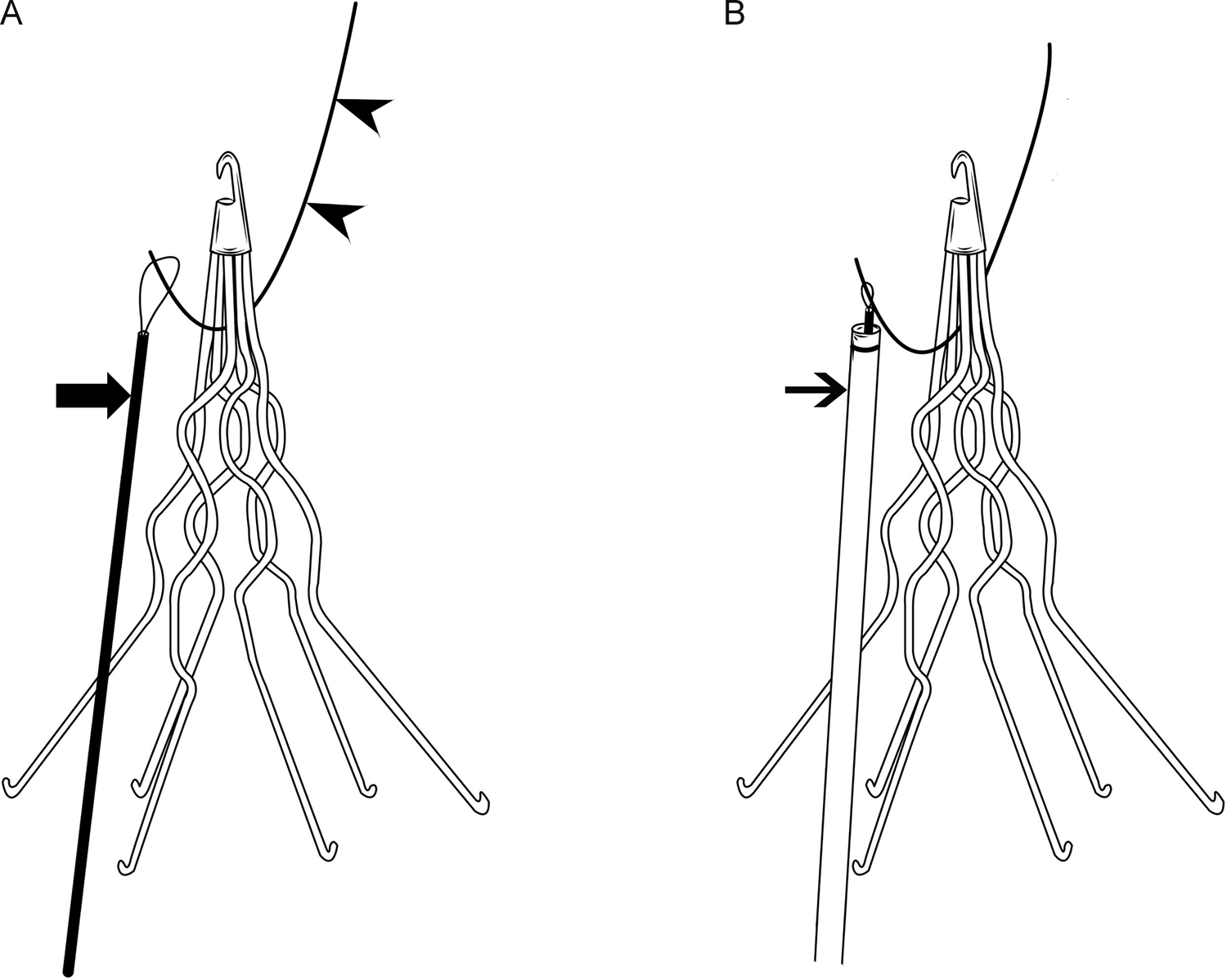
A, Diagram showing the tip of a J wire (arrowheads) entrapped in the apex of a filter. Note the tip of the entrapped wire is accessible for snaring, and a goose neck snare (large arrow) is inserted from a femoral approach to grasp the exposed guide wire tip and free it. The guide wire can then be pulled down through the filter and removed via the femoral vein. B, If any resistance is encountered, or the filter begins to move, a long introducer sheath or guide catheter (small arrow) is advanced over the snare device to brace the filter as the guide wire is snared.
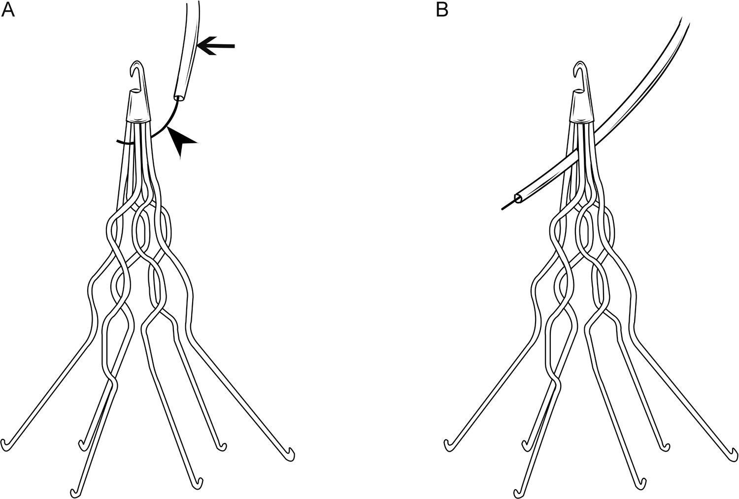
A, Diagram showing the tip of a J wire (arrowhead) entrapped in the apex of a filter. Note the tip of the entrapped wire is inaccessible to snaring. A 5- or 6-F angiographic catheter (small arrow) is advanced over the entrapped guide wire and used to push the guide wire away from the point of entrapment. B, After the wire is freed, the residual curve at the guide wire tip is straightened with the catheter to prevent reengagement as the wire is removed.
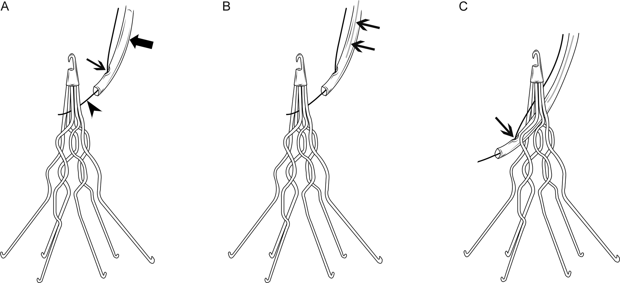
A, Diagram showing the tip of a J wire (arrowhead) entrapped in the apex of a filter. Note the tip of the entrapped wire is inaccessible to snaring. A flexible guiding catheter (large arrow) is advanced over the entrapped J-wire in a monorail (rapid exchange) fashion. This was achieved by creating a side-hole (small arrow) about 2 to 4 cm from the tip of the guiding catheter. B, Amplatz wire (small arrows) was introduced inside the guiding catheter to provide support and prevent kinking of the guiding catheter when pushed downward to free the wire. C, The J wire freed from the filter. Notice the freed J wire is projecting out of created side hole (small arrow) in the guiding catheter.
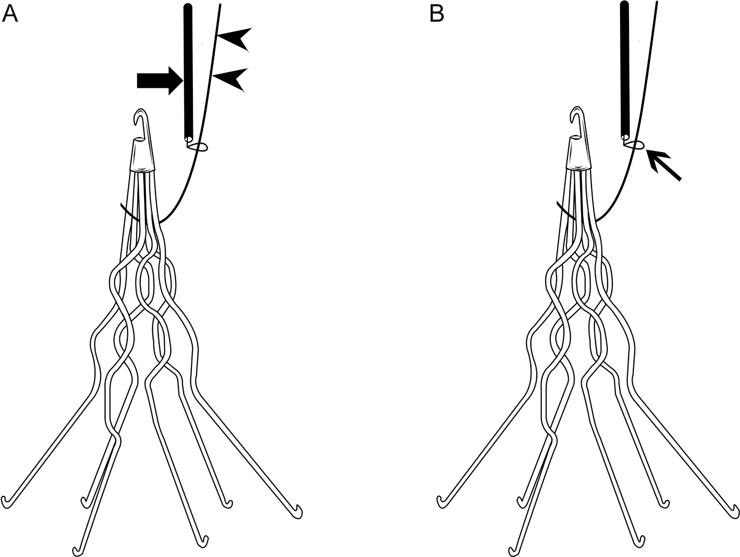
A, Diagram showing the tip of a J wire (arrowheads) entrapped in the apex of a filter. Note the tip of the entrapped wire is inaccessible for snaring. There is only a short length of the entrapped guide wire protruding from the access site. A goose neck snare (large arrow) is advanced over the short protruding portion of the wire in a monorail fashion. B, The entrapped wire is engaged and grasped by the snare (small arrow) close to the point of entrapment. The snare is then used to push the guide wire caudally away from the point of entrapment to free it from the filter.
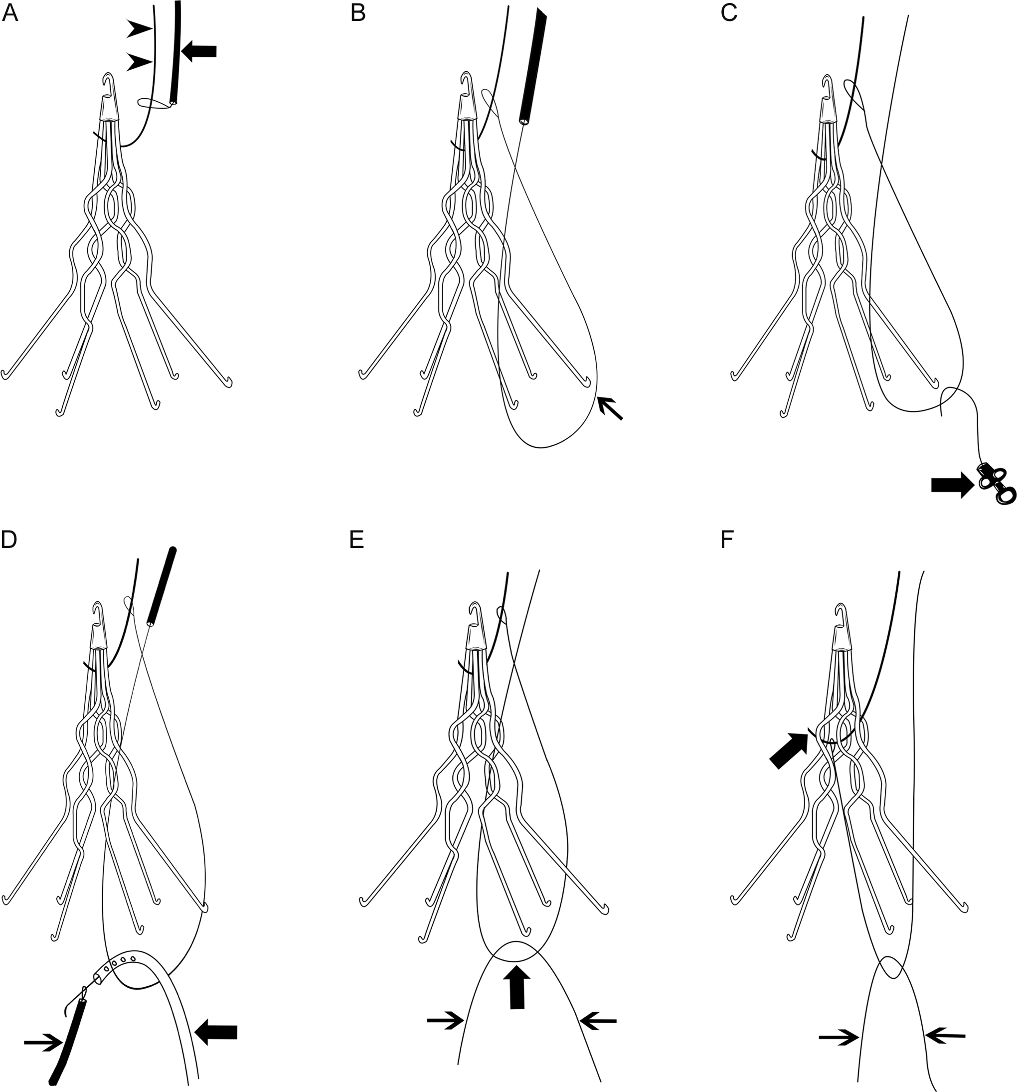
The “rail and reins” technique. A, Diagram showing the tip of a J wire (arrowheads) entrapped in the apex of a filter and the tip of the entrapped wire is inaccessible for snaring. There is only a short length of the entrapped guide wire protruding from the access site. A goose neck snare (large arrow) is advanced caudally over the entrapped guide wire to the point of entrapment (the “rail”). B, By further advancing the snare, the redundancy of the snare creates a secondary loop in the snare below the filter (small arrow). C, A tip deflecting wire and 5F pigtail catheter (large arrow) are used to engage the secondary loop of the snare via a femoral vein approach, and inferior (caudal) traction on the secondary loop of the snare can free the wire. D, A glide wire and pigtail catheter (large arrow) are used to engage the secondary loop of the snare via a femoral vein approach and the glide wire is then snared from a contralateral femoral approach (small arrow). E, Both ends of the glide wire (small arrows) protruding out of both groins and the body of the glide wire are engaged with the secondary loop of the snare (large arrow). F, Both ends of the glide wire (the “reins”; small arrows) exiting both groins are pulled inferiorly (caudally) with equal and gradually increasing force and the entrapped guide wire (large arrow) is freed from the filter.
The “in situ snare” technique. A, Diagram showing the tip of a J wire (arrowhead) entrapped in the apex of a filter. Note the tip of the entrapped wire is inaccessible for snaring. A 6- or 7-F introducer sheath or guiding catheter (large arrow) is advanced through the filter leg interspaces from a femoral approach. A goose neck snare (curved arrow) and a glide wire (small arrow) are then advanced together through the sheath or guiding catheter, and placed on opposite sides of the entrapped guide wire, and the free tip of the glide wire is then grasped by the snare. B, The snared glide wire is drawn back through and out of the catheter, leaving the mid portion of the glide wire looped around the entrapped wire (small arrow). C, The introducer sheath or guiding catheter (large arrow) is advanced over the looped glide wire, to grasp the entrapped guide wire within the loop (in situ snare). Inferior (caudal) traction upon the loop/catheter assembly will pull the entrapped wire downward and free it from the filter.
In certain occasions, and when all techniques and maneuvers fail to disengage the entrapped wire from the filter, the exposed portion of the wire can be cut at the skin surface. 2
Several precautions are proposed to decrease the risk of guide wire entrapment. The best option is to prevent the complication from occurring at all. 26 The lack of awareness of the presence of the IVC filter (noted in several case reports) or of this potential complication by the clinician during CVC placement or exchange over guide wires is the root cause of this complication. Before a CVC is inserted in any patient, the clinician should specifically ask whether a filter is in place. 2 Patient education, providing identification cards, adhesive label for the patient’s chart, or bracelet may also help reduce this complication. 2,26 A detailed preoperative evaluation to identify patients with an IVC filter is recommended since some of the incidents are documented during placement of CVC by anesthesiologists in the operating room. 25 Continued physician education about the risks of guide wire entrapment is important since early recognition of guide wire entrapment, without forceful retraction on the wire, will allow patients to be transported to the interventional suite for safe guide wire removal under fluoroscopic guidance. 31 In case of prior knowledge of the presence of an IVC filter, all CVC manipulations (new insertions or exchanges) should be performed with straight guide wires, or under fluoroscopic guidance. 1,2,13,25,28
The CVC kits could be equipped with guide wires that do not have small diameter (1.5 or 3 mm) J tips. In addition, long wires should not be used for blind placement of CVC. 31 Most CVC kits come with a standard size guide wire (60 cm at our institution), which allows deeper insertion of the wire from femoral, internal jugular, and subclavian access locations. Close attention must be paid to the depth of guide wire and the clinician should introduce only the length of guide wire that is necessary to secure vascular access. 2 The length can be estimated by laying the guide wire over the thorax from the insertion site to the angle of the manubrium (sternal angle). 28 As such, the guide wire should not be inserted more than 15 to 20 cm from internal jugular or subclavian approach, and probably less from a femoral approach. 26 If there is any doubt, the procedure should be done under fluoroscopic guidance. 26 Alternatively, placement of only 45 cm guide wires in CVC kits is recommended and is long enough for placement of 15 to 20 cm CVC. 31
In conclusion, with the rapid growth of retrievable IVC filters and the increasing placement of prophylactic IVC filters, we expect guide wire entrapment to increase. Guide wire entrapment can result in deleterious outcomes for patients and mandate a heightened awareness by physicians. Prior knowledge of a patient’s history of IVC filter placement and careful selection and manipulation of guide wire used in CVC insertion in these patients is imperative. In case of guide wire entrapment, the operator should stop pulling immediately and further manipulations should be done by an interventional radiologist under fluoroscopic guidance for safe retrieval of the guide wire without damaging or dislodging the IVC filter, or traumatizing the IVC.
Footnotes
Acknowledgment
We would like to thank Anthony Zagar and Patricia Moore for their efforts in producing the line art. We would also like to thank Ashleigh Timmerman for her help in preparing the manuscript.
Declaration of Conflicting Interests
The authors declared no potential conflicts of interest with respect to the research, authorship, and/or publication of this article.
Funding
The authors received no financial support for the research, authorship, and/or publication of this article.