
Abstract
Objective:
We developed a duplex ultrasound simulator and used it to assess accuracy of volume flow measurements in dialysis access fistula (DAF) models.
Methods:
The simulator consists of a mannequin, computer, and mock transducer. Each case is built from a patient’s B-mode images that are used to create a 3-dimensional surface model of the DAF. Computational fluid dynamics is used to determine blood flow velocities based on model vessel geometry. The simulator displays real-time B-mode and color-flow images, and Doppler spectral waveforms are generated according to user-defined settings. Accuracy was assessed by scanning each case and measuring volume flow in the inflow artery and outflow vein for comparison with true volume flow values.
Results:
Four examiners made 96 volume flow measurements on four DAF models. Measured volume flow deviated from the true value by 35 ± 36%. Mean absolute deviation from true volume flow was lower for arteries than veins (22 ± 19%, N = 48 vs. 58 ± 33%, N = 48, p < 0.0001). This finding is attributed to eccentricity of outflow veins which resulted in underestimating true cross-sectional area. Regression analysis indicated that error in measuring cross-sectional area was a predictor of error in volume flow measurement (β = 0.948, p < 0.001). Volume flow error was reduced from 35 ± 36% to 9 ± 8% (p < 0.000001) by calculating vessel area as an ellipse.
Conclusions:
Duplex volume flow measurements are based on a circular vessel shape. DAF inflow arteries are circular, but outflow veins can be elliptical. Simulation-based analysis showed that error in measuring volume flow is mainly due to assumption of a circular vessel.
Introduction
Volume flow is a primary parameter for the assessment of dialysis access fistulas. A minimum flow rate of 500 to 600 mL/min is necessary to support successful hemodialysis, and the measurement of volume flow in the inflow artery or outflow vein can be used to predict continued patency, confirm maturation, and determine when additional intervention is indicated. 1 –3 Duplex ultrasound scanning is an accurate noninvasive diagnostic technique for assessing the anatomy and function of dialysis access fistulas. Significant stenosis involving an inflow artery or outflow vein can be identified on duplex scanning by a focal velocity increase, and an estimate of volume flow can be obtained based on velocities and vessel diameter. 2,4
Simulation is playing an increasing role in medical training, and ultrasound simulators are available for both cardiac and vascular ultrasound. 5 Most applications of medical ultrasound depend on 2-dimensional (2D) B-mode (gray-scale) imaging alone. However, duplex ultrasound combines B-mode imaging with pulsed Doppler flow detection, and flow characteristics are displayed as spectral waveforms and color-flow images. In the vascular applications of duplex ultrasound, classification of disease severity is based primarily on focal velocity changes and the flow patterns detected in the imaged vessels. We have developed a duplex ultrasound simulator that incorporates realistic Doppler spectral waveforms and color-flow images along with B-mode images and used it to document the accuracy of peak systolic velocity measurements in carotid artery and dialysis access fistula models. 6,7
In order to provide a more complete and clinically relevant simulation, the capability to perform volume flow measurements was added to the duplex simulator for dialysis access fistulas. Because the duplex ultrasound simulator can provide true values for flow parameters such as peak systolic velocity and volume flow, the use of the simulator provides an opportunity to assess the accuracy of volume flow measurements. The objective of this study was to determine the accuracy of volume flow measurements obtained with the duplex simulator in dialysis access fistula models and identify possible sources of error.
Methods
Simulator Design
The duplex ultrasound simulator hardware is shown in Figure 1 and consists of a personal computer, a mannequin with a left arm, and a mock transducer whose spatial location and orientation are measured using a tracking device (Patriot; Polhemus Inc., Colchester, Vermont, USA). 6 As the examiner manipulates the mock transducer over the mannequin, the computer displays ultrasound images in a standard 2D B-mode view that changes in real-time according to the transducer’s position and orientation. 8 The procedure for creating the dialysis access fistula models, simulating flow patterns within these models, and performing a simulated duplex ultrasound scan with velocity and volume flow measurements is described in the following sections.
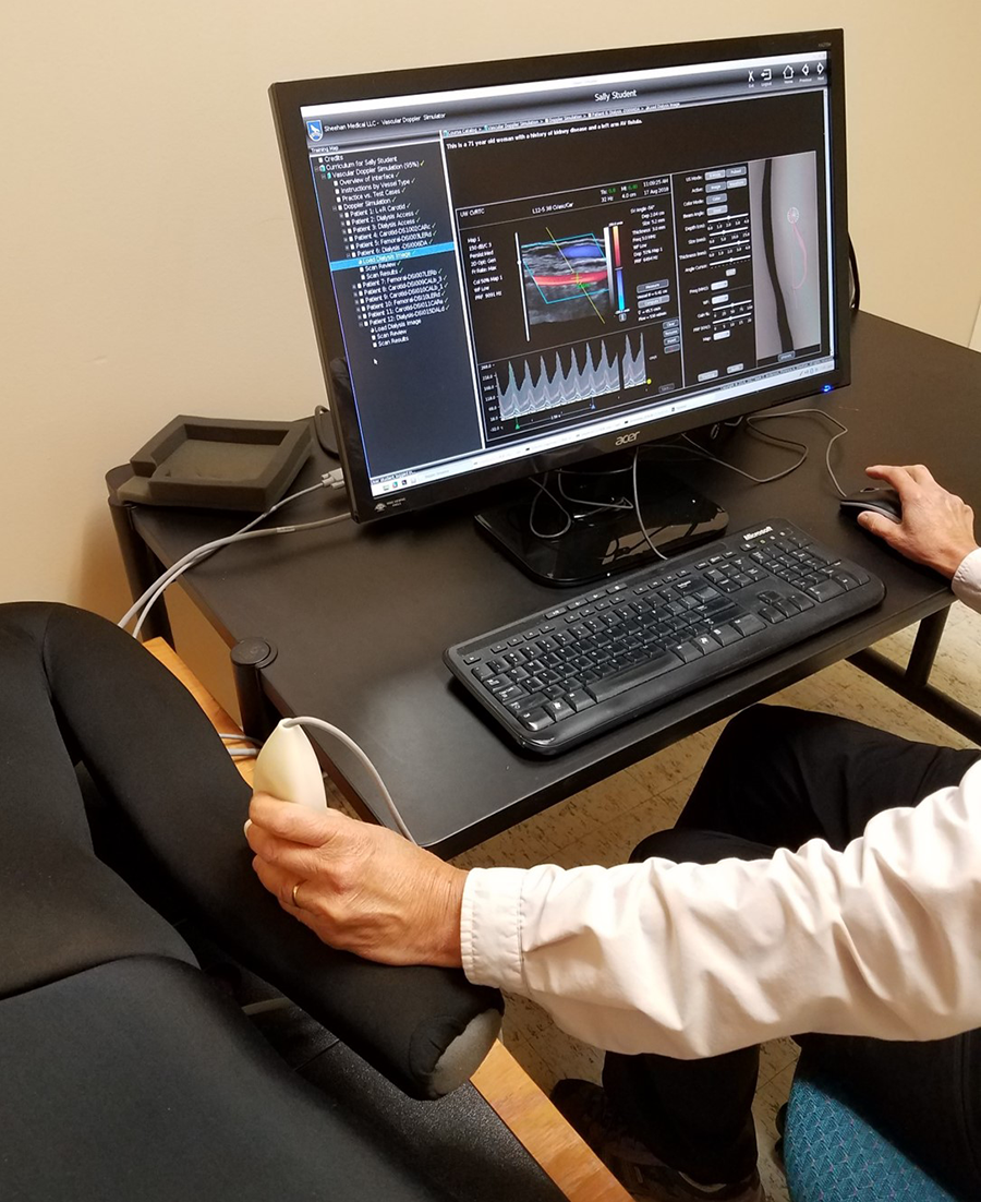
Duplex ultrasound simulator hardware. The computer display, mannequin with a left arm, and mock transducer are shown. A spatial tracking system records the position and orientation of the mock transducer in real-time; a magnetic field transmitter is located inside the mannequin and a receiver is fixed inside the plastic transducer housing.
Image Construction and Flow Modeling
Three-dimensional (3D) ultrasound scans were performed on 4 patients with dialysis access fistulas following a duplex ultrasound examination performed for a clinical indication. Three models were end-to-side fistulas (end of vein anastomosed to side of an artery) and 1 was a side-to-side fistula (side of artery anastomosed to side of a vein) using the brachial artery in 3 patients and the radial artery in 1 patient. The imaging procedure was approved by the institutional review board of the University of Washington, and the subjects gave informed consent.
The 3D ultrasound data sets included B-mode images of the dialysis access proximal inflow artery, arterial–venous anastomosis, distal artery, and proximal outflow vein as previously described. 7 Closely spaced 2D B-mode images were acquired along the length of the vessels using an ultrasound transducer with an attached tracking device (Flock of Birds; Ascension Technology Corp., Burlington, Vermont, USA) and reformatted into a regular 3D grid (Figure 2A). The vessel lumens were then traced for 3D reconstruction of the vessel as a surface mesh. Computational fluid dynamics modeling was applied to calculate 4-dimensional (4D) flow velocity fields inside the vessel lumen (Figure 2B). 9 –11 The fluid velocity and pressure are solved inside the vessels of interest with spatial resolution on the order of 100 microns and temporal resolution of 1 ms. Ten cardiac cycles are simulated and then phase-averaged to obtain a velocity field representative of the blood flow in the dialysis access fistula. The 4D velocity database is exported to the simulator as 3 components of velocity at each node of the computational mesh and for each time step of the cardiac cycle. These data provide the true velocities for every point within the imaged vessels. The 4 dialysis access fistula models used in this study are illustrated in Figure 3.
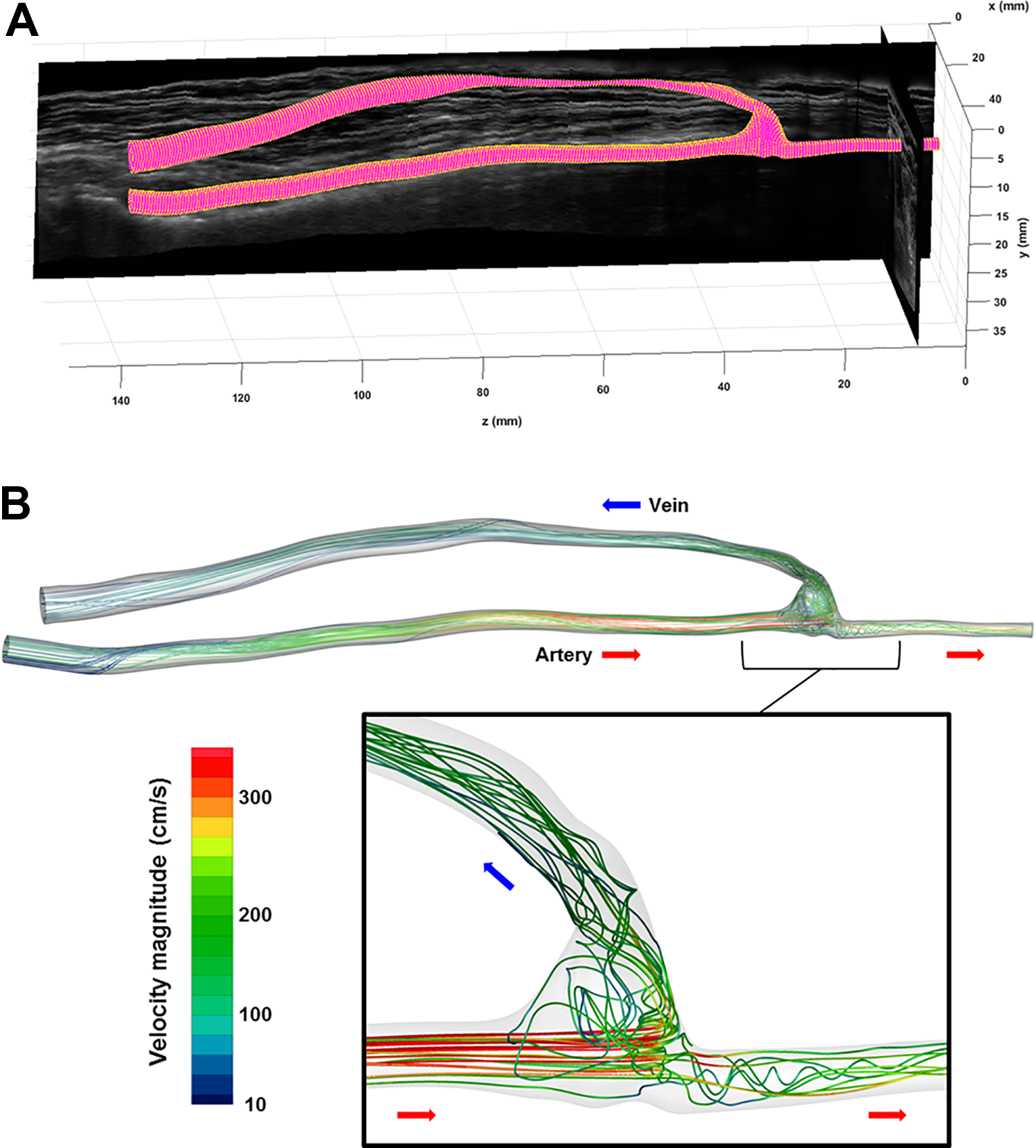
Three-dimensional vessel reconstruction and flow modeling. A, A set of 900 2D B-mode (gray-scale) ultrasound images acquired with 3D location and orientation data are reformatted in a 3D gray-scale volume. Mesh reconstruction from manual outlines of the vessel lumens produces a 3D surface model of the arterial and venous segments of the dialysis access fistula. B, Representative velocity path lines (trajectories of blood particles from the arterial inlet to the outlets) calculated by the computational fluid dynamics simulation are shown for peak systole; the path lines are color-coded by velocity magnitude (color bar). The inset shows details of the flow at the anastomosis. The direction of the flow is indicated by the colored arrows (artery, red; vein, blue). 2D indicates 2-dimensional; 3D, 3-dimensional.
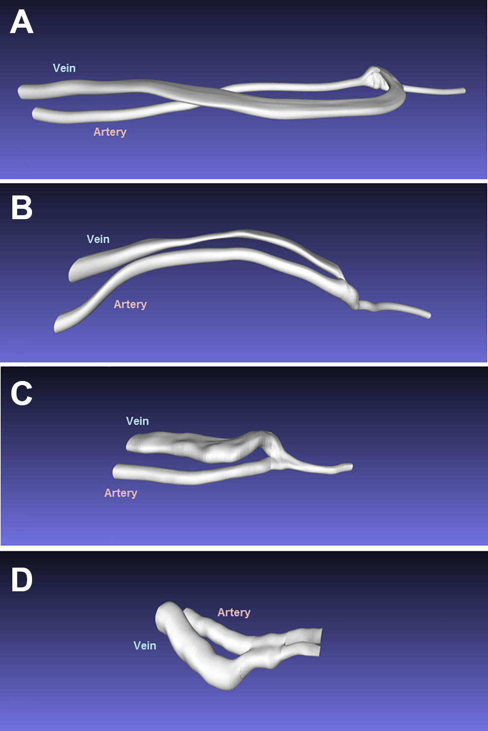
Three-dimensional vessel lumen models for the 4 dialysis access fistula cases used in this study. A and B are end-to-side fistulas (end of vein anastomosed to side of an artery) between the brachial artery and basilic vein. C is an end-to-side radial artery to cephalic vein fistula. D is a side-to-side fistula (side of artery anastomosed to side of a vein) between the brachial artery and cephalic vein.
Examiner Interface and Scanning
When the mannequin is “scanned,” the computer displays B-mode images in views corresponding to the transducer position and orientation (Figure 4). A control panel on the computer display shows settings analogous to a real duplex ultrasound system, and the examiner is required to steer the Doppler beam, select the size and depth of the Doppler sample volume within the B-mode image, specify the Doppler angle relative to the long axis of the vessel, and adjust the pulse repetition frequency or velocity scale. To enhance the realism of the simulator, the computational fluid dynamics velocity vector fields are projected onto the Doppler beam, converted to a color-flow map, and animated in real-time.
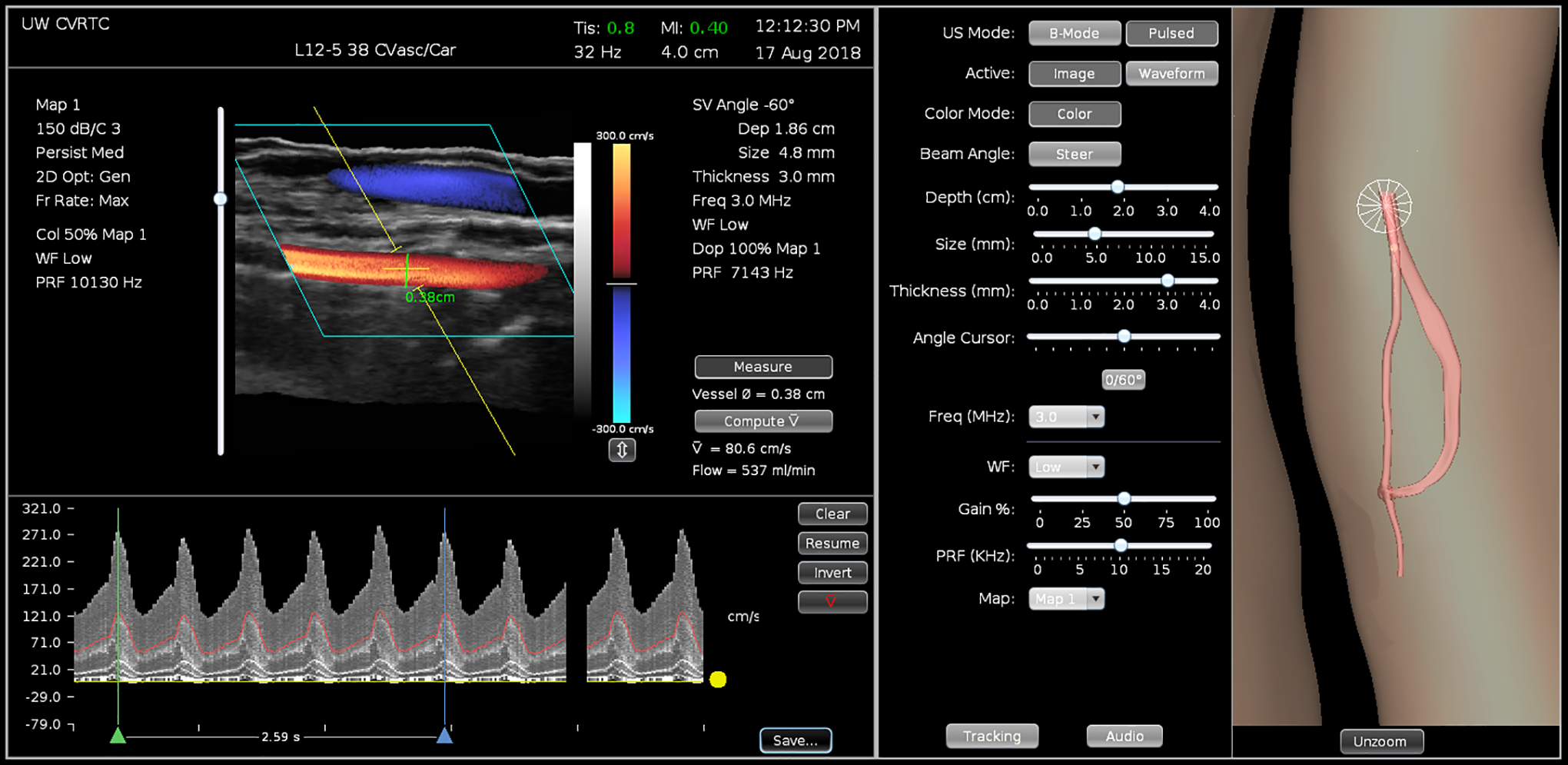
Duplex ultrasound simulator examiner interface for a dialysis access fistula with a volume flow measurement. The left panel includes the B-mode and a color-flow image showing the inflow artery (red) and outflow vein (blue). The pulsed Doppler sample volume is expanded to include the entire lumen of the inflow artery and the vessel diameter measurement is displayed. Spectral waveforms recorded from the Doppler sample volume location are shown with 5 cardiac cycles bracketed for determination of the time-averaged blood flow velocity. The colored line in the spectral waveform represents the mean velocity. Calculation of volume flow (537 mL/min) is based on the vessel diameter (0.38 cm) and time-averaged velocity (80.6 cm/s). The center panel displays the controls for the B-mode and Doppler settings. The right panel is a 3D display showing the location of the dialysis access fistula model, the transducer (cone), and the 2D image plane on the mannequin. This part of the display is intended for training; it can be disabled for competency testing. 2D indicates 2-dimensional; 3D, 3-dimensional.
Doppler spectral waveforms are simulated by retrieving the velocities calculated within the 3D model of the vessel lumen and projecting the 3 components of the velocity within the Doppler sample volume onto the Doppler beam. The stored 4D velocity field within the 3D Doppler sample volume is converted to a spectral waveform display that is updated in real time according to the specific settings selected by the examiner. A real-time audio output of the Doppler shifts corresponding to the spectral waveforms is also available on the simulator.
Volume Flow Measurements
A procedure for obtaining volume flow measurements was implemented on the simulator following the same approach that is used with duplex scanners in the clinical setting, as shown in Figure 4. With the vessel of interest imaged in a longitudinal view, the Doppler sample volume was placed in the center of the vessel and expanded to include the entire lumen, and the vessel diameter was measured at the site of sample volume placement. Using a beam-to-vessel Doppler angle of 60°, a spectral waveform was recorded and the time-averaged velocity calculated over an interval defined by the examiner that spanned approximately 5 cardiac cycles. This time-averaged velocity was based on the time average of the mean velocities of each of the velocity spectra occurring during the specified interval.
Volume flow was calculated as: Q = v × A × 60 seconds = v × π (d 2)/4 × 60 seconds, where Q is the volume flow (mL/min), v is the time-averaged velocity (cm/s), A is the cross-sectional area of the vessel at the site of velocity measurement (cm2), and d is the lumen diameter (cm). Multiplying by 60 seconds is necessary to express Q in mL/min. The internal diameter of the vessel was measured from the B-mode and color-flow image in the longitudinal view and used to calculate the cross-sectional vessel area assuming a circular lumen.
The standard duplex ultrasound volume flow calculation described above is based on a circular vessel shape. The true dimensions of the simulated vessel were determined by intersecting the 3D surface mesh with the plane of the sample volume and fitting an ellipse to the intersection points. The area of the ellipse was used to calculate the true volume flow. Eccentricity (ecc) was computed as
Validation
The accuracy of volume flow measurements obtained by examiners performing a duplex scan of a dialysis access fistula model was determined by comparing the volume flow measured from the simulated spectral waveforms to the true value provided by computational fluid dynamics, as described above. The deviation is expressed as a percent of the true volume flow. Four experienced examiners (2 vascular sonographers, 1 vascular surgeon, and 1 ultrasound engineer) performed simulated duplex scans on 4 dialysis access fistula models and measured volume flow at 3 locations in the inflow artery and 3 locations in the outflow vein, for a total of 96 measurements. Examiners were instructed to lift the mock transducer off the mannequin and re-scan after each measurement so that the measurements would be independent.
Statistical Analysis
The mean absolute deviation between true and measured values for volume flow was computed using the paired t test. The deviation was compared between observers using Welch analysis of variance. Multiple regression analysis was used to test the dependency of error in volume flow measurement on an error in measuring blood flow velocity and vessel cross-sectional area.
Results
Each of the 4 examiners made 6 volume flow measurements on each of the 4 dialysis access fistula models for a total of 96 measurements, 48 in an inflow artery and 48 in an outflow vein (Table 1). The volume flow measured by the examiners deviated from the true value by 35% ± 36% overall. There was no significant difference in mean absolute deviation in volume flow between the 4 examiners; however, the measurements by Examiner 2 differed significantly from the true value. Review of images from the volume flow measurements made by Examiner 2 showed that in 4 of the 24 measurements, the Doppler sample volume was placed away from the midline of the vessel, resulting in a smaller diameter measurement and lower time-averaged velocity than would have been obtained with proper sample volume placement in the center of the vessel lumen. This error in scanning technique resulted in lower calculated volume flow measurements relative to the true value, as indicated in Table 1. The examiner error in determining the time-averaged velocity was NS (44 ± 33 cm/s vs the correct value of 45 ± 32 cm/s, P = NS).
Comparison of True Versus Measured Volume Flow Rates for the 4 Examiners Scanning the 4 Dialysis Access Fistula Models.a
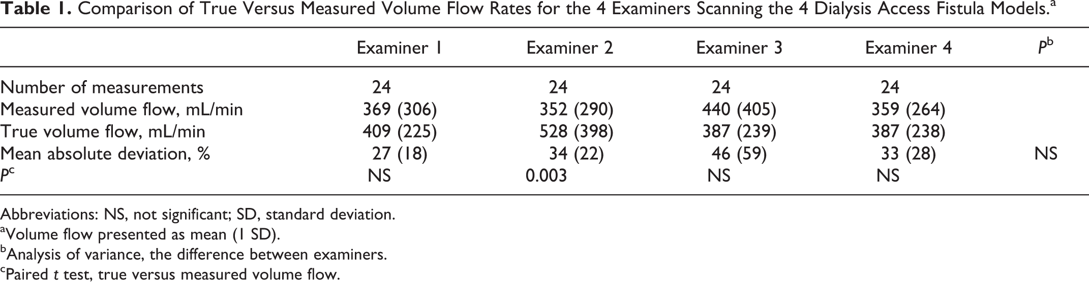
Abbreviations: NS, not significant; SD, standard deviation.
aVolume flow presented as mean (1 SD).
bAnalysis of variance, the difference between examiners.
cPaired t test, true versus measured volume flow.
The mean absolute deviation from the true volume flow was smaller for the inflow arteries than for the outflow veins (22% ± 19%, N = 48 vs 58% ± 33%, N = 48, P < .0001). This is because the standard duplex ultrasound volume flow calculation assumes a circular vessel lumen shape which significantly underestimated the true cross-sectional area of the outflow veins based on the area of an ellipse (0.16 ± 0.07 cm2 vs 0.24 ± 0.20 cm2, P < .00001). The eccentricity of the inflow arteries was significantly lower than the outflow veins (0.47 ± 0.13 vs 0.85 ± 0.7, P < .00001), indicating that the veins had a more elliptical shape (Figures 3, 5, and 6). The results of the regression analysis indicated that the error in measuring vessel cross-sectional area was a significant predictor of error in volume flow measurement (β = 0.948, P < .001), but the error in determining time-averaged velocity was not (β = 0.203, P = NS). The overall model fit was r 2 = 0.884. When the volume flow measurement was based on an area calculation using an ellipse fit to the major and minor axes of the true vessel cross section, overall deviation from the true volume flow was reduced from 35% ± 36% to 9% ± 8% (P < .000001).
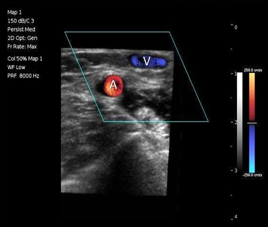
Transverse B-mode and color-flow image of a dialysis access fistula from the duplex ultrasound simulator showing the circular inflow artery (A) and the elliptical outflow vein (V).
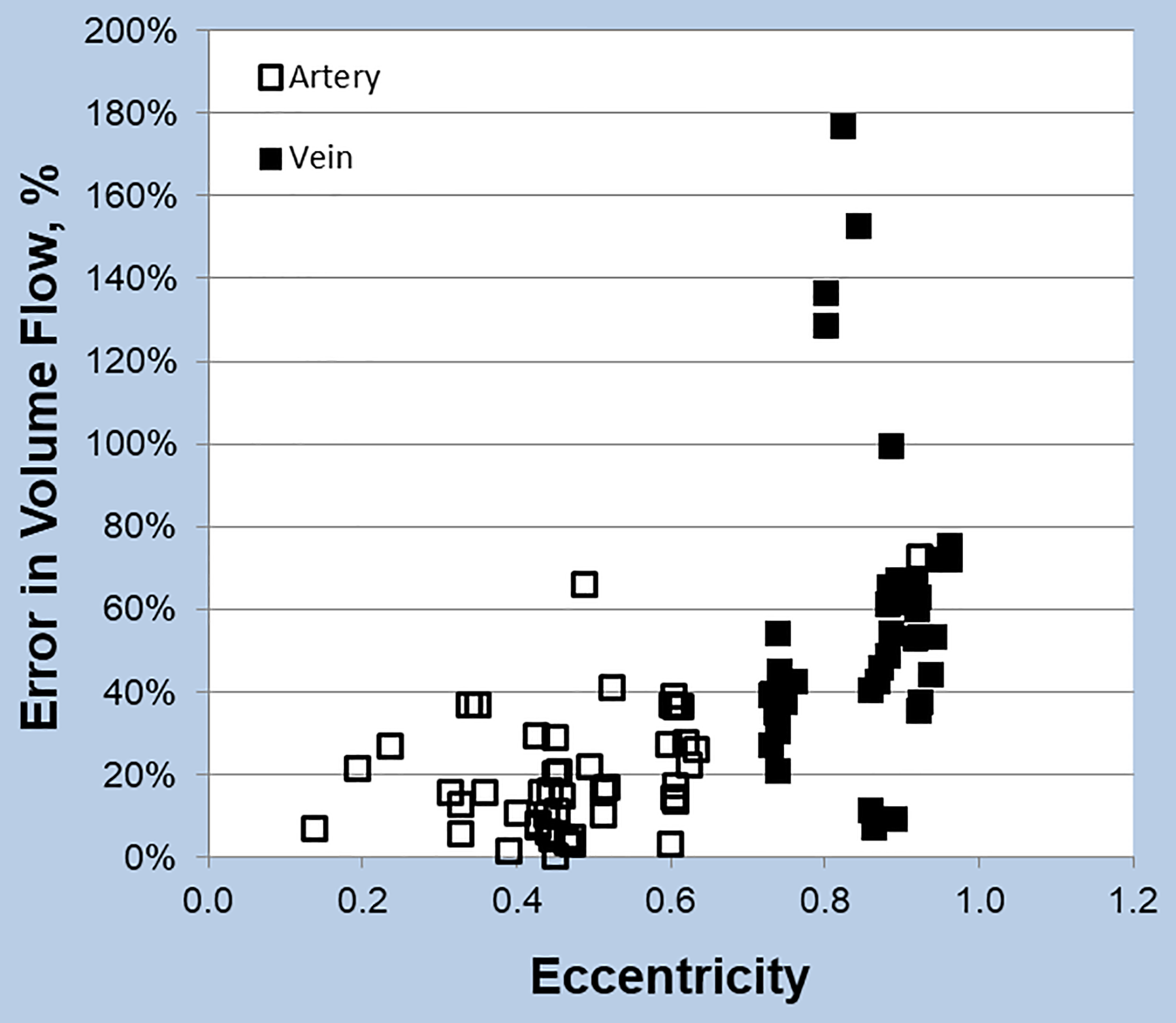
Relationship between error in volume flow measurement and vessel eccentricity. Error is smaller for vessels with a circular cross section (low eccentricity). The inflow arteries tended to be circular, while the outflow veins had a more elliptical shape.
Discussion
Simulators are assuming a more prominent role in medical settings for both procedural training and assessment of psychomotor skills. 5,8 Duplex scanners are the primary instrumentation for vascular ultrasound, but simulating the Doppler component of duplex scanning presents unique technical challenges. The duplex ultrasound simulator we developed at the University of Washington uses 3D models of vessel geometry and computational fluid dynamics modeling to provide a realistic representation of arterial flow displayed as Doppler spectral waveforms and color-flow images.
Because peak systolic velocity is the primary parameter for classification of arterial stenosis severity with duplex scanning, initial validation of the duplex simulator focused on assessing the accuracy of peak systolic velocity measurements in carotid artery and dialysis access fistula models. When 3 examiners made 36 peak systolic velocity measurements on 2 carotid artery models, the mean absolute deviation from the true peak systolic velocity was 8% ± 5% and was similar between vessel segments and between examiners. 6 With the dialysis access fistula models, 4 examiners made 43 peak systolic velocity measurements on 2 models (24 arterial segments and 19 venous segments), and the mean absolute deviation from the true peak systolic velocity was almost identical at 8% ± 6%. 7 There was no significant difference in the mean deviation of peak systolic velocity measurements between arterial and venous segments in the dialysis access fistula models. These results demonstrate that an examiner can measure peak systolic velocity from the spectral waveforms using the settings on the simulator with a mean absolute error of less than 10%.
While peak systolic velocity is important for classification of stenotic vascular lesions, volume flow is the key feature of dialysis access fistulas that determines the success of hemodialysis, with a minimum rate of 500 to 600 mL/min required. 1,3 Measurement of volume flow with duplex ultrasound has been validated against more direct methods such as ultrasound dilution and timed blood collection. 13,14 However, the standard method used for calculating volume flow with duplex ultrasound also includes potential sources for error. Accurate volume flow measurements require a regular or uniform flow pattern. With a dialysis access fistula, variations in lumen diameter, vessel tortuosity, and turbulence are more likely to occur in the venous conduit or outflow vein, while the inflow artery—usually the brachial artery—has a relatively laminar flow pattern and tends to be straight and relatively constant in diameter. Consequently, duplex ultrasound protocols for assessing dialysis access fistulas have advocated measuring volume flow in the inflow artery rather than the outflow vein. 2,4
The use of computational fluid dynamics modeling in the duplex ultrasound simulator provides true values for velocities and volume flows that can be compared with those measured by an examiner during a simulated duplex scan. This makes it possible to assess the accuracy of the measurements and the skill of the examiner, as well as to identify sources of error. 5 Review of images from the volume flow measurements made by examiner 2 in this study indicated a specific source of error involving scanning technique with improper placement of the Doppler sample volume.
Volume flow measurements obtained by duplex scanning are based on a time-averaged velocity and the cross-sectional area of the vessel lumen. The area calculation requires a diameter measurement and assumes a circular vessel shape. In this study, on dialysis access fistula models, the volume flow measured by the examiners deviated from the true value by 35% ± 36% overall, but the mean absolute deviation from the true volume flow was significantly smaller for the inflow arteries than the outflow veins. The examiner error in determining the time-averaged velocity was NS, but the error in measuring vessel cross-sectional area was a significant predictor of error in volume flow measurement. As shown in Figures 3 and 5, the inflow arteries of the dialysis access fistula models tended to be uniform in size and circular, while the outflow veins were highly variable in shape. When the area calculation was based on an ellipse rather than a circle, the overall absolute deviation from the true volume flow was reduced to 9% ± 8%.
A limitation of the dialysis access fistula models used in the duplex ultrasound simulator is that the shape of the vessels is fixed. The vessel walls do not pulsate with the cardiac cycle, and they are not deformable with transducer pressure as they would be in a live patient. This constraint may have contributed to the eccentricity that was observed in the outflow veins in the dialysis access fistula models; however, the patient B-mode images used to create the 3D surface models were obtained with minimal probe pressure to avoid any significant compression of the vessels. We have not correlated the measured or true volume flow rates in the dialysis access fistula models with the corresponding volume flow rates obtained during dialysis. While this would be interesting, the goal of our study was to compare the volume flow rates as measured by duplex ultrasound in a simulated setting with the true flow rates in the models as determined by computational fluid dynamics modeling. The shape or geometry of each of the dialysis access fistula models was based on ultrasound images from a patient, but volume flow rates also depended on arterial inflow and venous outflow conditions which may not have been identical in the model simulation and patient access site during dialysis.
Conclusions
The findings in this study serve to emphasize the importance of an accurate cross-sectional area determination in the duplex ultrasound volume flow calculation. Volume flow measurements obtained by duplex scanning are based on a time-averaged velocity and the cross-sectional area of the vessel lumen. This analysis of volume flow measurements made with a duplex ultrasound simulator on dialysis access fistula models indicated that error in measuring volume flow is mainly due to the assumption of a circular vessel shape. The inflow arteries of the dialysis access fistula models tended to be circular, but the outflow veins were more elliptical. For best accuracy, duplex ultrasound volume flow measurements should be obtained from inflow arteries or a site where the vessel is relatively circular. If that is not possible, accuracy could be improved by using the major and minor axis dimensions of the vessel to compute an elliptical cross-sectional area.
Footnotes
Authors’ Note
Dr Sheehan supports research in medical education by lending TTE simulators from her laboratory at the UW to investigators for up to 6 months. None of the other co-authors of the present report nor the UW have involvement in Sheehan Medical LLC and none receive any benefit from simulator sales.
Declaration of Conflicting Interests
The author(s) declared the following potential conflicts of interest with respect to the research, authorship, and/or publication of this article: Dr Sheehan is the founder of VentriPoint, Inc. of which she is a major equity holder. VentriPoint markets a product for measuring right heart function which is not the subject of the present report. Dr Sheehan is also the founder and President of Sheehan Medical LLC which markets the transthoracic and transesophageal echocardiography simulators that she and co-investigators developed and validated at the University of Washington (UW) and the vascular Duplex ultrasound simulator. Mr Anderson is a co-founder of Sheehan Medical LLC and the Company’s Chief Architect.
Funding
The author(s) disclosed receipt of the following financial support for the research, authorship, and/or publication of this article: This research was supported by funding from the National Institute of Biomedical Imaging and Bioengineering and the National Institute of Environmental Health Sciences, National Institutes of Health, Bethesda MD (R42EB018124).