
Abstract
Tunnels are a challenging environment for radio communications. In this paper we consider the use of autonomous mobile radio nodes (AMRs) to provide wireless tethering between a base station and a leader in a tunnel exploration scenario. We propose a tethering algorithm for AMR motion control based on a consensus variable protocol. Using radio signal strength measurements, the AMRs autonomously space themselves so as to achieve equal radio distance between each entity in the chain from the base station to the leader. Experimental results show the feasibility of our ideas.
1. Introduction
Subterranean spaces play a critical role in the infrastructure of modern society. Engineered underground environments such as tunnels and subway systems are an important part of the infrastructure used to transport commerce and people throughout the world. Likewise, tunnels and caves are important environments for military and homeland defense. However, subterranean spaces present unique challenges compared to other environments. Topology restrictions constrain the flows of people, equipment, material, water, air, and communication. And, while vulnerable to unforeseen events that can compromise their operation, such as fires, terrorist attacks, or structural failure such as cave-ins, underground environments are also subject to extreme physical conditions such as high temperatures and humidity, toxic and/or explosive gases, and airborne contaminants. 1 For activities such as emergency response and exploration in subterranean spaces, the ability to keep people out of harm’s way becomes essential. Recent legislation has resulted in increased use of fixed infrastructure in civilian underground environments for environmental monitoring, vehicle and personnel hazard monitoring, networked video surveillance systems, and advanced communication systems. However, in emergency situations such fixed infrastructure can become ineffective, thus making search and rescue difficult and dangerous. Likewise, cave and tunnel exploration cannot exploit fixed infrastructure, again leading to difficult and dangerous conditions for humans.
In this paper we address one aspect of enhancing safety in subterranean search and rescue or for tunnel and cave exploration: the problem of radio communications in the absence of a fixed infrastructure. Motivated by the idea of networked radios2,3 and our own and others’ work to form a communication chain using robots,4,5 including the Darpa Landroids project (http://www.darpa.mil/ipto/programs/ld/ld.asp), we consider the use of autonomous robots that can act as an autonomous mobile radio nodes (AMR) for enhancing communication in tunnels.
Consider the scenario depicted in Figure 1. Shown is a two-dimensional plan of an underground mine. Notionally, a cave-in has blocked access to a portion of the mine equipped with a sensor network that provides monitoring and communications for personnel who may be trapped in the back part of the mine. Because mine environments in an emergency can be very dangerous, it is preferable to attempt to clear the rubble via tele-operation and inspect the tunnels remotely before human rescue teams enter the mine. However, the nature of radio propagation in underground tunnels is such that typical commercial tele-operation systems will not be able to provide non-line-of-sight (NLOS) communication with the rubble-removal equipment from the surface. Although it is possible for the equipment to pull a communication tether or to deploy a ‘daisy-chain’ of fixed-location radio relays, the scenario depicted in Figure 1 suggests another approach: the use of AMRs that act as relays for data to-and-from the remote equipment and eventually to-and-from the underground sensor network. The advantage of using autonomous relays is that the AMRs can automatically adjust to find the optimal AMR-to-AMR spacing for the specific situation at hand, without the need for a priori calculation of the spacing, where ‘optimal’ means providing for the best possible radio communication between all the units.
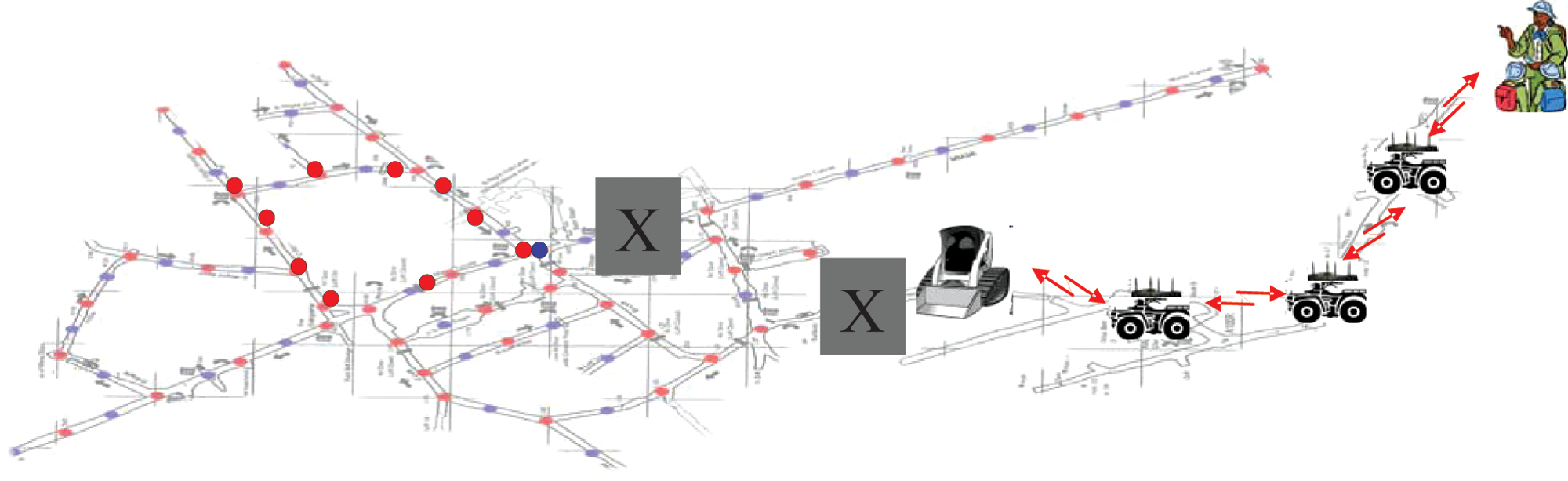
Autonomous mobile relay node scenario.
In the following we detail the results of a series of experiments aimed at the scenario depicted in Figure 1. As noted, our approach is motivated by ideas for using wireless networked mobile robots as tools for enhancing wireless networks, such as using motion control of wireless mobile robots to bridge network gap 6 and by the idea of wirelessly-tethered exploration with mobile robots. 7 Wireless tethering ensures inter-robot communications by controlling the movement of the robots so they do not move out of communication range with each other. While some results reported in the literature consider line-of-sight (LOS) tethering, in which robots can only move until they lose optical LOS with each other, 8 wireless tethering controlled by received signal strength (RSS) measurements allows direct NLOS links between robots, and has been reported to decrease the amount of time spent by a robot swarm in mapping a given environment, compared with LOS-based tethering. 9 Thus, in our approach we propose an RSS-based tethering system whereby an AMR attempts to maintain equal RSS between itself and a leader and between itself and a base station. Our system controls the RSS-spacing using the consensus variable approach, 10 which has been used for formation flying and robot cooperation in unmanned air vehicles 11 as well as for ground robots. To the best of our knowledge, there is no existing work aimed at achieving prescribed RSS separation between entities in a group of mobile robots in an underground environment. We also comment that the problem of underground communication could perhaps be addressed using small, non-mobile communication relays that could be dropped off and picked up as needed. However, we envision extensions of our ideas whereby a team of mobile robots maintains communication with itself, but not necessarily with a base station, in which case the use of AMRs is preferred to static radio relay nodes.
The paper is organized as follows. We begin with a description of the hardware platforms that we developed for the project. Then we discuss the radio frequency (RF) environment in tunnels, including an experimental characterization obtained in our school’s experimental mine. Next we describe results from four different radio tethering experiments, each demonstrating one or more of the components of the scenario shown in Figure 1. These include:
outdoor radio tethering with one autonomous follower that uses wall-following-based steering control (this experiment uses the autonomous vehicle platform discussed in Moore et al. 14 );
underground person-in-the-loop radio tethering with an autonomous (human) follower;
underground person-in-the-loop radio tethering with one semi-autonomous follower (human steering the AMR with autonomous velocity control based on radio signal strength);
underground wireless radio tethering with one autonomous follower, using steering controlled via a wall-following algorithm and autonomous velocity control based on radio signal strength, using an NLOS tele-operated Bobcat front-end-loader as the leader.
In the experiments described below ‘radio tethering’ means the scenario depicted in Figure 2. As shown, there is a leader (possibly static or mobile) and a base station. The goal is for the AMR to autonomously move so as to achieve the same RSS between itself and the base and between itself and the leader. Although the experiments described involve only one follower, the ideas are easily extended to multiple followers (see Moore et al. 14 ) and if there is more than one follower, then the goal of each AMR is to equalize the signal strength between itself and the radios behind and in front of the AMR. The meaning of ‘person-in-the-loop’ is explained in the appropriate sections below. Finally, note that we do not discuss the generic issues related to underground robotics, but refer the interested reader to the recent survey. 1 Likewise, we do not provide extensive details of the RF models and consensus variable-based control algorithms used, but focus instead on our implementations. The interested reader is referred to Weiss et al. 12 and the references therein for technical information about our radio propagation models and control algorithms. We also refer the interested reader to Moore et al. 14 for more information about the generic UGV auto pilot architecture we have developed and that was used for all the autonomous vehicles in the experiments.
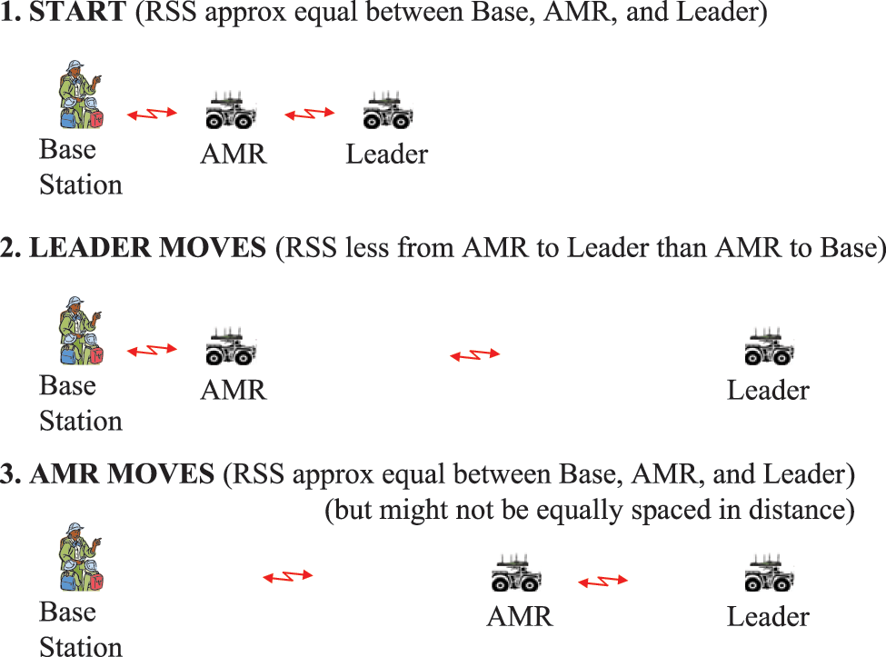
Radio tethering experimental scenario.
2. System Components
The system components developed in this project included two different AMRs (one based on a ‘mini-Baja’ vehicle and the other on an ‘EZ-Go’ golf cart), a tele-operated Bobcat vehicle, and a mesh radio infrastructure. Additionally various operator interfaces were used. In this section we detail these system components, with the exception of the mini-Baja vehicle, which was described in Moore et al. 14
2.1 Golf Cart-based AMR
Figure 3 shows the EZ-Go golf cart that was modified to enable drive-by-wire and drive-by-computer operation, thus enabling its use as an AMR. Modifications included actuation, sensor additions, on-board computing, and operator interfaces, each described below.
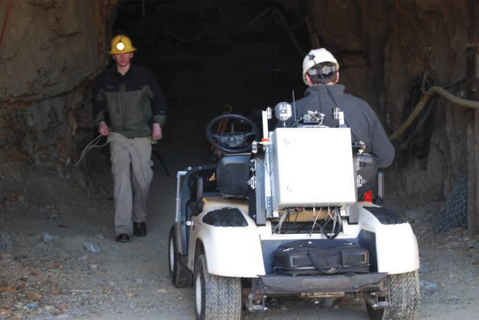
EZ-Go AMR in the Colorado School of Mines’ Edgar Mine.
2.1.1 Vehicle Actuation
The vehicle actuation requires special consideration due to the requirement that manual operation needs to be preserved. The golf cart’s steering and brake are entirely mechanical, whereas the throttle is an electromechanical system which uses an inductive sensor to sense the position of the throttle pedal. A RoboteQ motor control board drives the steering and brake actuators to a position set point using a proportional-derivative-integral (PID) control algorithm.
The steering is actuated using a geared-down servomotor mounted near the steering wheel. The servomotor’s rotation is mechanically linked to the steering shaft via a timing belt and two timing pulleys. To allow for manual operation without back-driving the servomotor, the timing pulley on the steering shaft is allowed to freely spin on the shaft. A separate splined assembly fixed to the steering shaft is pinned to the free-spinning timing pulley, mechanically linking the pulley rotation to the steering shaft. By sliding the splined assembly axially, the mechanical connection between the steering shaft and timing pulley can be engaged or disengaged allowing the operator to change between manual and electronic steering control.
The brake is more seamlessly integrated, using a guided rod and linear actuator to push directly on the brake arm. At any time, the operator can manually push on the brake, and the rod will simply move in the guide. Conversely when the linear actuator extends, the rod moves until it makes mechanical contact with the brake arm and thus pushes in the brake.
The throttle is actuated by simply placing a circuit in parallel with the throttle sensor which mimics the same functionality. Applying a pulse width modulated signal to the circuit changes the voltage at the sensor line used by the golf cart speed controller. Because the circuit is in parallel with the sensor, manual and electronic throttle operations are available at all times.
2.1.2 Sensors
There are a total of six propreoceptive sensors on the AMR: a Hall Effect sensor on each wheel to measure odometry and calculate vehicle speed, a spring-loaded potentiometer on the steering arm to measure the Ackerman steering angle, and a five degree of freedom Inertial Measuring Unit (IMU) to measure vehicle orientation. Combined, these sensors provide steering angle, velocity, and yaw, all necessary to compute Ackerman vehicle dynamics.
For environmental sensing there are currently 14 sonar ranging sensors that symmetrically surround the AMR and measure the distance to the wall or obstacle, as shown in Figure 4. These sensors have a range between 15 cm and 6 m.
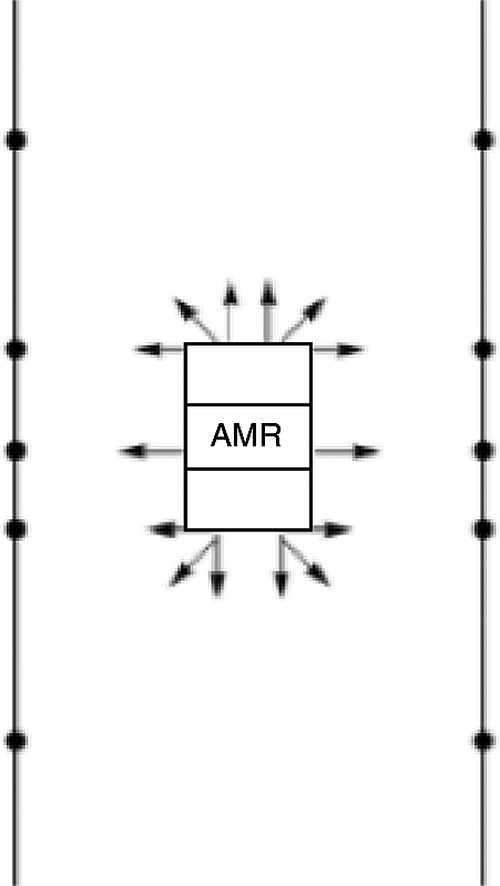
AMR sonar positions.
Sonar sensors are ideal in mining environments because the diffuse mine walls scatter sound waves, allowing the sensor to easily detect the wall. However, these sensors have some drawbacks because they have a slow update rate and are prone to interference from neighboring sensors. To help alleviate the slow update rate, the 14 sensors are broken up into four triggering groups; each triggering group has between two and four sonars, all triggered simultaneously. These triggering groups cycle through every 55 ms, making the total update rate 5 Hz. To avoid interference, each sensor is oriented 90 degrees apart from other sensors in the group. Measurements from these sensors are used to build an environment model of mine walls.
One problem with the sonar sensors is that they are only accurate to ±2 inches, which causes problems when trying to build a good environment model. In the future, we plan to add a scanning laser sensor, which should dramatically improve accuracy. In addition, we may also add a stereovision system, which would allow us to build a three-dimensional environmental model, further improving accuracy, and therefore, navigation.
Another problem with the sonar sensors is that they have trouble getting range measurements at steep angles (from 45 degrees to parallel with the wall). Thus, we added four Sharp Infrared long-range sensors that are oriented towards the four corners of the vehicle at 45 degree angles. These sensors serve as ‘backups’ to the four sonars pointed in the same direction, in the event that the sonars have difficulty reading the mine walls at steep angles.
2.1.3 On-board Computing and Software Infrastructure
The computing structure consists of three hierarchical computer layers as shown in Figure 5. The lowest level (far right) is the servo controller. This controller is a RoboteQ AX3500, and sets the steering and brake actuators to commanded values using a PID loop. The middle computer layer is a digital signal processing Microchip PIC processor and handles all robotic functions such as analog to digital conversion, servo set point calculation, command processing, and speed control. This ‘robotic’ controller sends commands down to the servo controller and receives commands from the ‘autonomous’ controller via RS232 communication. The autonomous controller (far left) runs higher-level navigation routines.

Computer architecture.
The autonomous controller is implemented on a laptop and coded in the Python programming language. The autonomous controller communicates with the robotic controller via a USB to serial adapter. A communication packet structure was created to standardize communication and detect communication errors. The autonomous controller sends requests for sensor data, system status, or motion actions to which the robotic controller responds appropriately with data or vehicle motion. When enabled, the autonomous controller requests sensor data, processes it, and determines the appropriate motion commands to send to the robotic controller.
Several different steering controllers were implemented, including a fuzzy logic controller. However, in the final experiments wall-following control was accomplished using a proportional controller that steered to maintain the golf cart in the middle of the mine drift. Logic was used to account for side passages (detected by significant changes in sonar readings).
During radio tethering experiments, a separate program monitors RSS signal strength and intermittently sends distance values to the autonomous controller program. The autonomous controller uses a set speed and the proportionally-controlled steering controller to drive down the mine drift the specified distance. Once the AMR reaches the target distance it stops and notifies the other program. The AMR maintains its position for approximately 30 s and collects data before the next target distance is sent (more details about this data collection are given below). We note that the computational complexity of the vehicle steering and motion control algorithms is quite low. The one aspect of our approach that could have a high computational load is the logic to interpret the sonar data so as to localize the AMR relative to the expected mine map. For instance, in future implementations we may use SLAM (simultaneous localization and mapping) for this purpose, in which case additional processing capability may be required.
2.1.4 Operator Interfaces
The AMR has three user-selectable modes: manual, remote, and autonomous. In manual mode, the brake and steering actuators are disengaged, which allows a human operator to drive the golf cart without computer interference. In remote mode, the robotic controller takes over actuation, allowing a human operator to control the golf cart wirelessly using a standard hobby-grade transmitter and receiver pair. Finally, in autonomous mode, the autonomous controller takes over all actuation and automatically guides the AMR through the mine. Note that in addition to system-level vehicle control, various safety features were included in the vehicle operating systems, including watchdogs to stop movement when communication is lost between the AMR and the base station, proximity detection to stop movement when the AMR comes close to hitting something, and emergency shut-offs on the vehicle, the joystick, and the base station.
In autonomous modes, the operator operates the AMR through a small graphical interface written in Python (shown in Figure 6). Currently the interface is simple, utilizing buttons or keyboard commands to allow the operator to turn the steering controller on or off, to turn on data logging, or to add comments to the log files. A set of slider bars is also available which can be configured for PID tuning, speed, steering, or brake control. Future development will include indicators for system status and greater control of logging or system setup. The program may be started via command line or by double clicking on the Python file, and debugging information is displayed either in the command line window or a secondary window if opened by double clicking on the Python file.
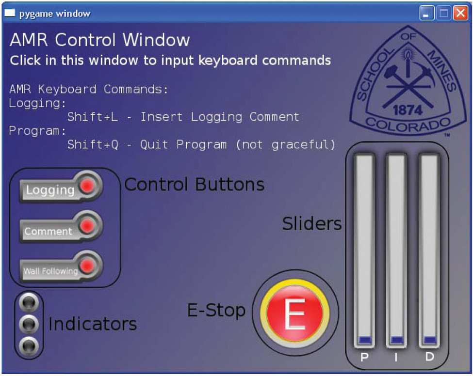
AMR interface.
2.2 Tele-operated Bobcat
New model Bobcat front end loaders have the added option of a remote control system. However, the factory remote control system uses a proprietary frequency hopping spread spectrum wireless transmission protocol. This communication protocol is incompatible with our Ethernet/Wi-Fi network, and could not be used for remote control within an underground mine environment. In order to make the Bobcat remote control system compatible with an Ethernet/Wi-Fi network two Ethernet enabled microprocessors were used to trick the remote control system into thinking it is receiving signals from its own electronics. One microprocessor reads information from the user, in the form of joysticks and switches. This microprocessor then communicates with the other microprocessor via an Ethernet/Wi-Fi channel. The second microprocessor then interprets the data and relays information in the form of simulated signals to the original Bobcat remote control system. With an Ethernet/Wi-Fi network, adding cameras and other Ethernet enabled devices is very easy since off the shelf components exist for most applications. Within our system we have cameras on every vehicle and will have multiple cameras on the Bobcat because it is tele-operated. Figure 7 shows the resulting architecture for the tele-operated Bobcat. Figure 8 shows the Bobcat tele-operation user interface hardware and an example of the video feedback available to the operator from the Bobcat.
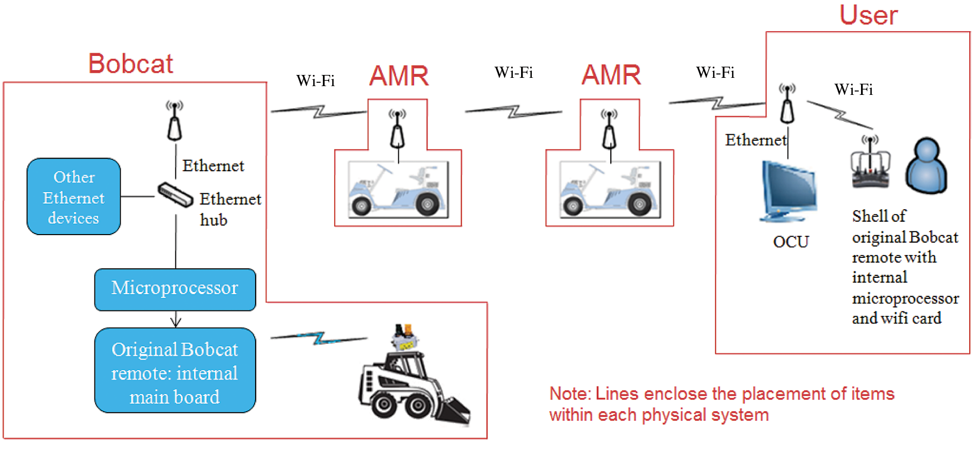
Bobcat tele-operation layout.
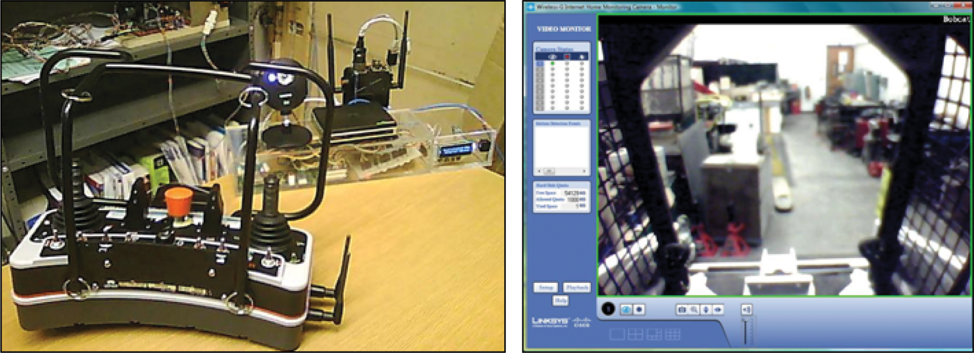
Bobcat tele-operation interface and video feedback.
2.3 Communication Infrastructure
To wirelessly transmit high bandwidth data, like video, a high frequency signal is required. Since real time video is necessary for tele-operation of the Bobcat front end loader, we need a high frequency signal to carry the information. Because of this high frequency signal requirement, and because of the many off-the-shelf components already available, we chose to use a standard 802.11 b/g Wi-Fi network. The company Rajant provides Wi-Fi equipment with the added ability to interconnect in an ad-hoc fashion and adapt to changing environments. Rajant Wi-Fi nodes connect to as many other Rajant Wi-Fi nodes that are within range, providing a highly redundant and reliable Wi-Fi network. The more nodes, the more resilient the meshed network becomes: if one node loses connection the data can be relayed through the other nodes to get the information across. Additionally, software provided by the vendor allows the ability to obtain and use the radio signal strength between connected units. We used Rajant ME2 Breadcrumb radios on each vehicle in our system as well as at the base station. Because these are commercial units, we do not discuss this part of the system in any more detail and note that there are other vendors who provide similar products that could also be used.
3. The Radio Environment in Tunnels
3.1 Overview of Experiments
The propagation of wireless signals within an underground mine or tunnel environment depends upon many parameters, such as the cross sectional shape of the mine, the composition of the surrounding rock, the curvature of tunnels, the position of antennas, and the RF used, among many others. In our project we use 802.11b/g Wi-Fi for the necessary high bandwidth communication. This standard Wi-Fi protocol uses a frequency of 2.4 GHz, which has a small wavelength in comparison to the dimension of the mine. Because the wavelength is small, there is minimal diffraction of waves around corners. Although there is a strong waveguide effect in many mine tunnels, there is also large bending loss around corners. For straight tunnels, the loss is less than in free space because of waveguiding (reflections from the walls, if you will, for the frequencies of interest). However, at a bend, non-specular scattering due to the surface roughness of the walls and the low reflection coefficient of the walls result in high losses. Thus, getting wireless signals around corners is dependent upon reflected waves. Further the reflection of waves is a very inefficient process because most of the wave energy is absorbed into the walls of the mine. What this means for transmitting wireless information in an underground mine, is that LOS placement of equipment is the best means of transmitting and relaying high frequency signals.
We performed several experiments within the Edgar experimental mine to quantify the distance versus signal strength for a few tunnels within the Edgar mine (note: these are in addition to previous work conducted by some of us on this problem; see Moore and Weiss 13 and the references therein for additional information on this topic). We took tests of LOS and NLOS environments within the Miami and Army tunnel sections of the mine (we refer to these tunnel sections by their name for delineation, but do not show them on a map due to space limitation; please contact the authors for more information). The experiments were performed using two Rajant ME2 BreadCrumb Wi-Fi nodes, at transmitter power of 34 dBm, and omni-directional TX and RX antennas. In the experiments the first node was placed at 0 ft and the second node was placed at several locations at varying distances from the first node. Signal-to-noise ratio (SNR), which has a direct correlation to the signal strength in a noiseless environment of the mine, was recorded at several distance points along the tunnels.
3.2 Experimental Results
The first tests we performed were using the straight sections of the Miami tunnel and Army tunnel. The cross sectional shape of the Miami tunnel has a rough diameter of about 8 ft, while the Army tunnel has a diameter of about 15 ft. The SNR versus LOS distance results for the Miami tunnel are shown in Figure 9(a) (the Army tunnel results are not shown). It is interesting to note that signals are not attenuated as quickly within the Miami tunnel as in the Army tunnel; this could be for many reasons, but most likely is due to a waveguide effect.
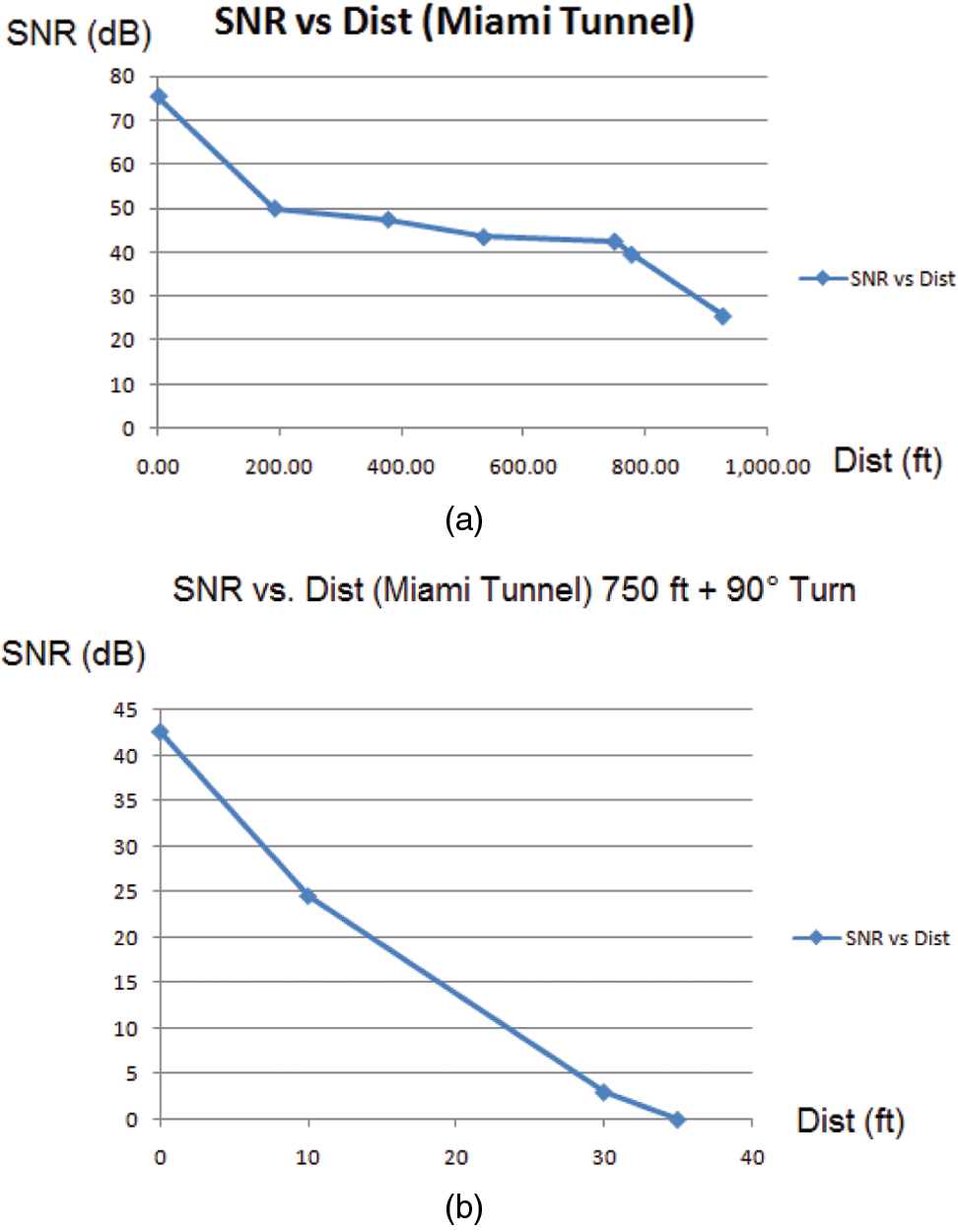
SNR versus distance (a) LOS; (b) NLOS, 90 degree turn.
The next tests considered a 90° turn at 750 ft within the Miami tunnel. Figure 9(b) shows the SNR versus NLOS distance as we moved into the turn at varying distances from the start of the turn. From the results, it is easy to see that signal strength is attenuated very quickly when a turn around a corner is taken within a mine. In the straight sections of the Miami tunnel we lose about 50 dB of signal strength in 1000 ft, whereas the attenuation is nearly 1.3 dB/ft around a 90 degree bend.
Note that the signal strength versus distance relationship for straight paths versus tunnels is highly dependent on the tunnel in question as well as on the exact placement of the radio antennas. We have detailed some of these dependencies in Weiss et al.12,13 The variability in SNR versus distance is another reason motivating the use of mobile robots for adaptively positioning radio relays in underground environments. While the data shown in Figure 9 can be used for approximate movement of the radios, such motion must be done iteratively (i.e. with feedback control) to account for the uncertainty in SNR versus distance for any specific tunnel.
4. Radio Tethering Experiments
As noted in the introduction, we will describe four sets of radio tethering experiments. We discuss each of these separately below.
4.1 Outdoor Radio Tethering with One Autonomous Follower
As a first step, and as a way to validate our algorithms, we prepared an experiment with one manned leader and one autonomous follower. The objective of this experiment is to equalize the RSS between the follower and the leader and between the follower and the base station, while following a wall at the left side of the follower. The experiment was located outside the Brown Hall, on the Colorado School of Mines campus. Figure 10 shows an aerial view of the location. As can be seen, the first half of the path is a semicircle with an approximate radius of 9 m, followed by a straight section about 20 m long. The base station was placed in the interior of the building. As a follower we used an electric mini-Baja vehicle with drive-by-wire capabilities shown in Figure 11 and described in Moore et al. 14 The algorithms described in Moore and Weiss 13 were implemented in a single board computer based on a Pentium-M processor, and were written in Python, using a multithreaded architecture. Two sonars (one in the left side and one in the front) were added to the mini-Baja to measure the distance to the wall. As a leader we used a manned golf cart. The leader and the follower, as well as the base station, were equipped with a Rajant Radio. The experiment starts with the follower at the start of the path, and the leader somewhere in front of the follower. When the autonomous mode in the follower is enabled, it moves forward until the RSSs are equal, while following the wall. Then the leader moves forward and stops, and the follower follows it, until the RSSs are equal. This sequence is repeated until the follower finishes the path. The problem was simplified by assuming that the mini-Baja only moves forward. There are two variables we want to control: the distance between the mini-Baja and the wall, and the difference between the RSSs. Since the mini-Baja is moving at fairly low speeds (smaller than 1 m/s), we can decouple the two variables, and control the distance to the wall through the steering, and the RSSs differences with the vehicle speed. The algorithmic basis for the latter control was given in Moore and Weiss 13 and is based on the so-called consensus protocol, where by the velocity of each AMR is adjusted according to:

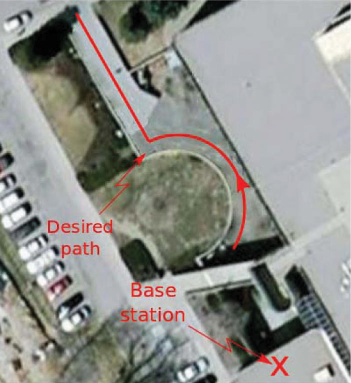
Aerial view of experiment.
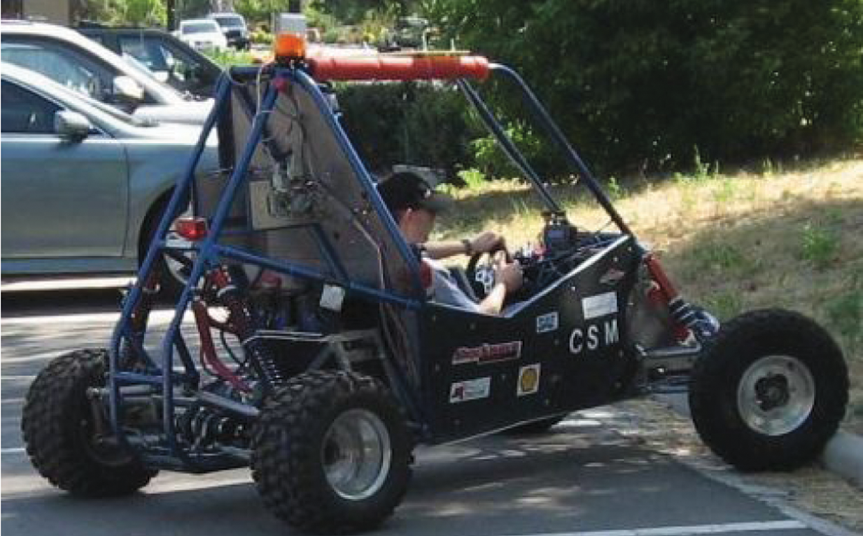
Electric mini-Baja.
Here
4.1.1 Wall-following Algorithm
The distance to the left wall is measured with a sonar mounted in the left side of the mini-Baja. In order to be able to negotiate the corner at the end of the circular arc of the path, we also added a sonar in front of the mini-Baja. The control objective is to keep a constant distance between the vehicle and the wall. To this end, we implemented a simple proportional controller that steers the car to the right if we are too close to the wall, and to the left if we are too far. Some extra logic switches were placed between the proportional controller and an ad-hoc behavior was used to negotiate the corner. The following is the function used for the steering controller:
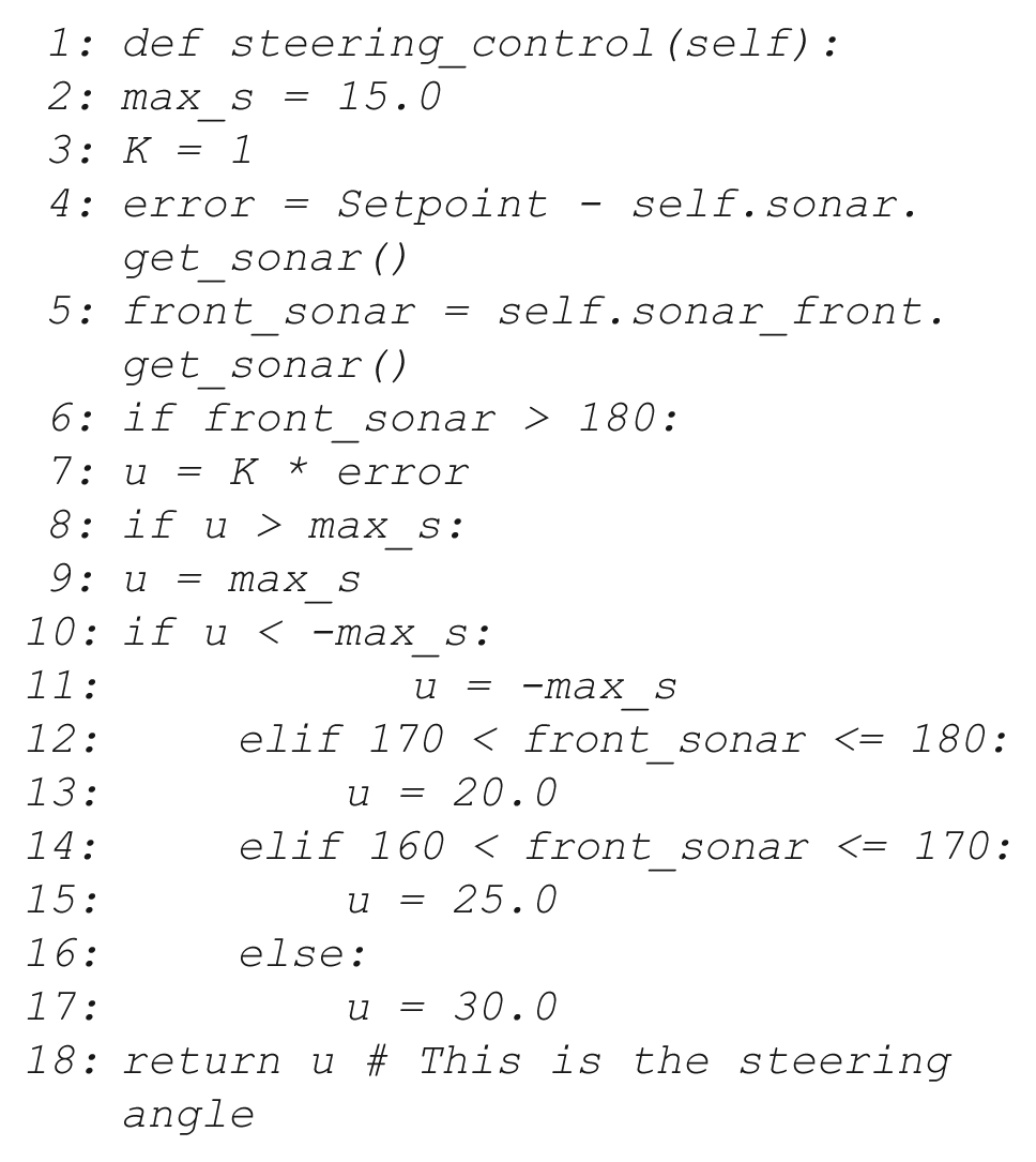
Lines four and five read the sonars and compute the error signal. If the distance between the front sonar is bigger than 180 inches, we execute the proportional controller. Lines eight to 11 check if the output of the controller is beyond the steering range of ±15 degrees used to follow the left wall. If the front sonar measurement is smaller than 180 inches, a right turn is executed.
4.1.2 Tethering Algorithm
To equalize the RSS difference, we query the Rajant radio mounted in the mini-Baja to get the RSS from the base station, and the RSS from the leader. The difference between these measurements is used as the error signal for a proportional controller that commands the speed of the vehicle. The code used for the RSS controller is shown below. Lines three to five query the Rajant radio to get the RSSs. Line seven computes the speed. Lines eight to 11 check that the speed is in the range 0–1 m/s:

4.1.3 Experimental Results
Figures 12 and 13 show the signals logged during one of the experimental trials (the experiment was repeated several times with varying degrees of success; the results shown here are typical). Figure 12 shows the left sonar signal and the corresponding steering angle. In this case, the setpoint was 75 inches. Initially, the vehicle is too close to the wall, and thus, the controller steers the car to the right. When the distance is greater than the setpoint, the controller steers the car to the left, keeping a constant distance with respect the left wall. Figure 13 shows the RSSs from the base station and from the leader. Initially, the RSS signal from the base station is greater than the RSS from the leader (we are too close to the base station), thus, the controller makes the mini-Baja move forward, making the RSSs approximately equal. Then the leader moves forward, which causes a decrease of its RSS. The controller responds by moving the Mini-Baja forward. Notice that by the end of the experiment, the RSS from the leader is higher than the RSS from the base station. However, since we are only allowing positive speeds, the controller cannot compensate for this difference (this is because in this experiment we did not have the ability to drive the vehicle backwards; the difference can be thought of as an overshoot in the control algorithms – as these were preliminary tests the results are not perfect).
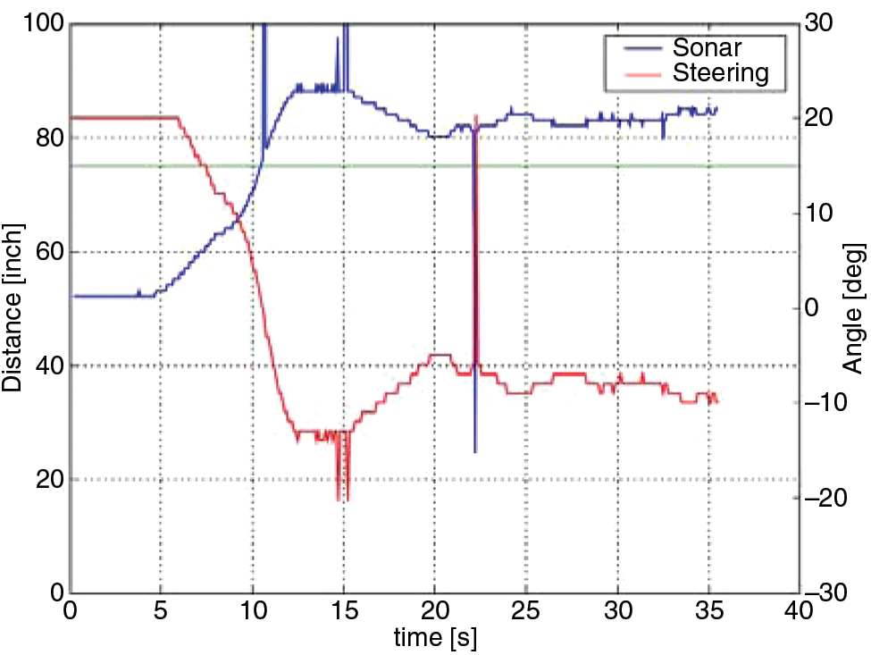
Steering controller results
Experimental result for the RSS controller.
4.2 Underground Human-in-the-loop Radio Tethering Experiment with an Autonomous Follower
We performed human-in-the-loop underground experiments simulating how a robot would navigate and position itself for optimal relaying of data. In these experiments ‘human-in-the-loop’ means that a human moved in response to commands from the AMR interface. Specifically, a laptop was associated with a radio and observed the RSS between the unit in front of and behind the radio. Computations were made and then directions were displayed to the human, directing them to either ‘MoveForward,’ ‘MoveBackwards’, or ‘Stop’. For all the underground tests (human-in-the-loop and autonomous), the tethering control was implemented slightly differently than as described in the previous subsection. Rather than directly computing speed, we based our algorithm on distance. Approximate SNR versus distance relationships (as in Figure 9) were used to compute an approximate move distance that would equalize the RSS and then the time was computed to travel a portion of that distance when driving at a fixed velocity. The net effect of this algorithm is a proportional controller-based consensus protocol. In all the underground experiments, data was collected for 30 s between moves of the AMR. Because the radio only provided updated RSS signals every 5 s, collecting data for 30 s allowed us to filter the data before using it in the motion update equation.
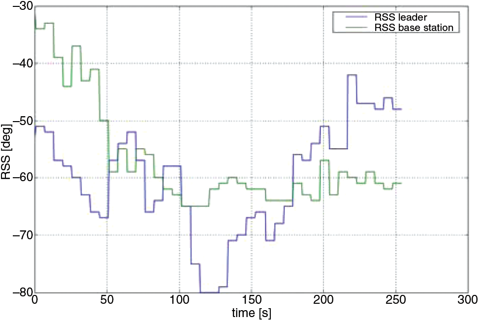
In these experiments there was one leader node far away from the base station and the AMR (a human in this case) moves to position itself at an equal radio signal strength away from both the leader and base station, acting as a relay for data from the leader to the base station. Figure 14 shows typical results from several such experiments, indicating that the system indeed did command the AMR (human) to move to the correct distance so that the RSS between the AMR and the base is essentially the same as between the AMR and the leader.
Human-in-the-loop experiment (one AMR).
4.3 Underground Human-in-the-loop Radio Tethering Experiment with One Semi-Autonomous Follower
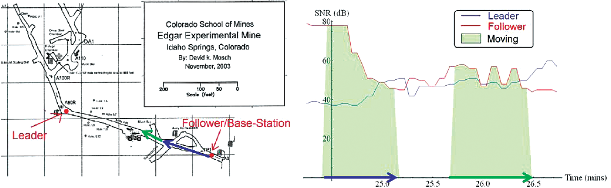
The third experiment used a single semi-autonomous follower. Here ‘semi-autonomous’ means that a human performed steering, as wall-following in the mine was not functional at the time of this test, due to damage sustained by several of the key sonar sensors during transport to the test site. As in the outdoor experiment described above, forward motion of the AMR was commanded by the RSS control algorithm and this command was executed autonomously. The only role of the human was to steer during AMR movements. The AMR navigated from the base station to the optimal position, guided by only the signal strengths to the leader and base station (follower) nodes. As in the previous section, the AMR would gather radio signal data for 30 s, and then move forward a prescribed distance computed by the position-based consensus algorithm. It would then repeat the gathering of data for 30 s and reposition again if necessary. The AMR repeated the gathering of data and moving five times during the experiment, until it ultimately reached its goal of equal signal strength between the leader and base station (follower). Movement control was executed as described in the previous subsection. Figure 15 shows the resulting signal strength plots and distance versus time. Figure 16 shows the corresponding locations in the mine. Clearly the algorithm was effective in achieving a balanced RSS between the AMR and the base and between the AMR and the leader.
SNR and distance versus time for the semi-autonomous AMR experiment.
AMR start/stop positions.
4.4 Underground Wireless Radio Tethering Experiment with One Autonomous Follower, Using the Tele-operated Bobcast as the Leader
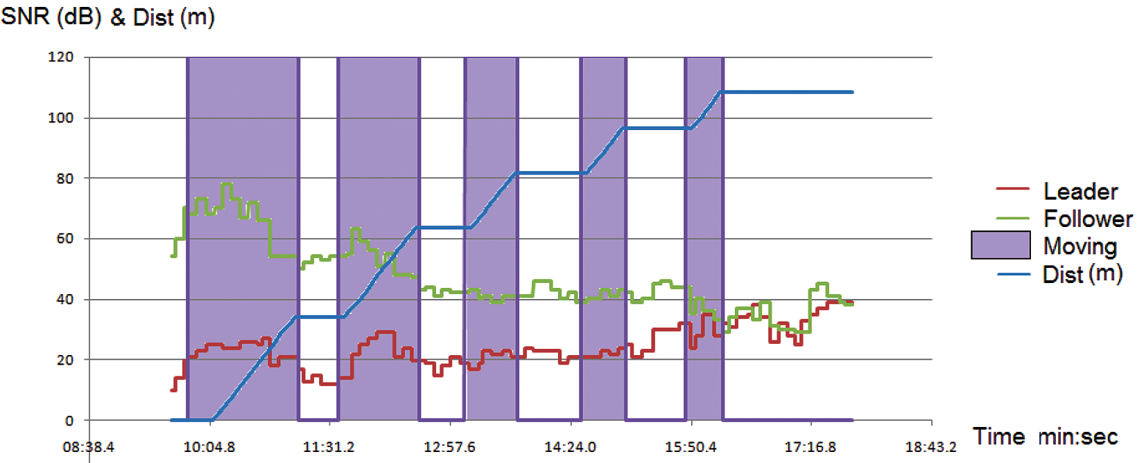
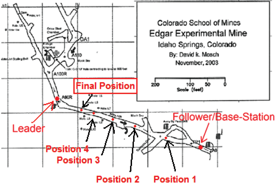
The final experiment reported here mimicked the full scenario depicted in Figure 2 above, where the leader was the tele-operated Bobcast front-end loader and the follower was an autonomous AMR that used sonar-based wall following to control steering and consensus-based motion control aimed at obtaining equal RSS between the follower and the leader and between the follower and the base station. The experiment started with the leader at a fixed location forward in the mine. During the test the operator drove the Bobcat forward continuously, using video feedback. The AMR moved forward to equalize the RSS, using the same 30 s data gathering interval and motion control algorithms described above. Figure 17 shows the resulting signal strength plots and distance versus time, from which it can be seen that the system did indeed act to equalize the RSS signals recorded by the AMR. Figure 18 shows the corresponding locations in the mine. Figure 19 shows several images from the test inside the mine. At left is a picture of the AMR following the Bobcat. Top right shows the operator driving the Bobcat using the images displayed on a laptop. Bottom right shows a view from the AMR video camera (the view used for driving would be similar to that in Figure 8 above).
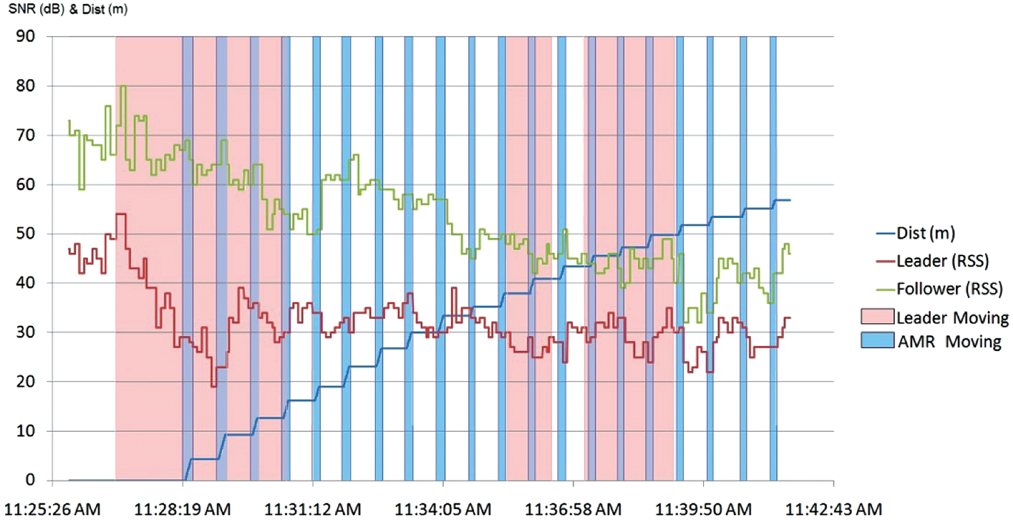
SNR and distance versus time for the autonomous AMR experiment with the Bobcat.
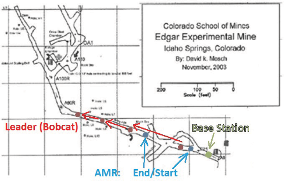
AMR start/stop positions for the autonomous AMR experiment with the Bobcat.
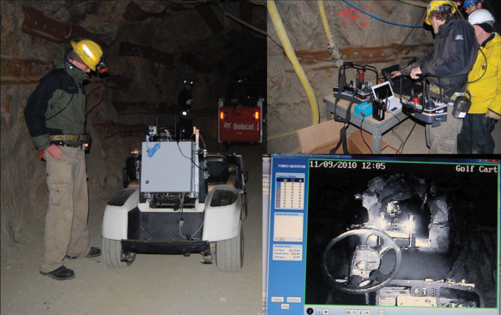
Images from the final end-to-end test.
5. Conclusions
We have described a series of successful experiments aimed at demonstrating AMRs for radio tethering in underground tunnels. Although we have conducted successful ‘human-in-the-loop’ experiments involving two AMR followers, additional work remaisns to demonstrate a complete autonomous system using multiple AMRs and realizing our vision of such systems acting as relays for tele-operation. Algorithmically, a major challenge is to develop control logic to recognize side passages and properly account for them so as to maintain correct center-of-the-tunnel navigation. Beyond that the challenges are primarily technological, as our experience shows the difficulties in developing rugged systems that can behave reliably in the harsh environments found in underground tunnels. Future work will address these challenges. Future work will also consider extension of the ideas to collaborative UAV/UGV radio relaying. Of particular interest is the possible use of helicopter-based systems in the underground environment, due to their ability to easily fly over the rubble and rough terrain typically found in underground environments.
Footnotes
This work was funded by the National Institutes of Health under grant number 1R01OH009612-01.
None declared.