
Abstract
In today’s network-centric world, aerospace vehicles interact with many objects. They navigate by overhead satellites, synchronize their flight paths with other vehicles, swarm over hostile territory and attack multiple targets. Studying these engagements with high-fidelity constructive simulations has become an important task of modeling and simulation (M&S). The simulation framework Computer Aided Design of Aerospace Concepts (CADAC) has its roots in FORTRAN code that dates back to the 1960s and was used by industry and the U.S. Air Force to simulate aerospace vehicles in all flight environments. To adapt CADAC to the new environment, a complete rewrite was carried out in C++, taking advantage of object-oriented programming techniques. The architecture of CADAC++ is based on the hierarchical structure of inherited classes. The vehicles (aircraft, missiles, satellites or ground targets), inherit the six-degree-of-freedom (6-DoF) equations of motion from the classes ‘Flat6’ or ‘Round6’, conveying either the flat or elliptical Earth model. In turn, these classes inherit the communication structure from the base class ‘Cadac’. The components of the vehicle, e.g., aerodynamics, propulsion and autopilot, are represented by modules, which are member functions of the vehicle class. Communication among the modules occurs by protected module-variable arrays. Every instantiated vehicle object is encapsulated with its methods and data. To communicate between vehicles, data packets are loaded onto a global data bus for recall by other vehicles. Input occurs by ASCII file and output is compatible with CADAC Studio, a plotting and data processing package. CADAC++ is chiefly an engineering tool for refining the components of the primary vehicle and exploring its performance as it interacts (possibly repeatedly instantiated) with the multi-object environment. Its modular structure enables reuse of component models across simulations. In the 10 years of development, CADAC++ based constructive simulations have been built for many types of aerospace vehicles and integrated with mission-level simulations.
Keywords
1. Introduction
High-fidelity, six-degree-of-freedom (6-DoF) simulations play an important part in the development of weapon systems. These so-called constructive simulations are used in technology trade studies, preliminary design, hardware-in-the-loop evaluation, flight testing and training. 1
The first all-digital, constructive simulations were created by the National Aeronautics and Space Administration (NASA), U.S. Department of Defense (DoD) and industry. In 1966 Litton Industries developed the architecture for a missile simulation in FORTRAN IV that had all of the features of a full 6-DoF simulation. It was the source of many derivatives by Hughes Aircraft, North American Aviation and Aerospace Corporation. Noteworthy is the U.S. Army ENDOSIM simulation. a The U.S. Air Force also adopted it to its own needs and named the simulation Computer Aided Design of Aerospace Concepts (CADAC).
AMTEC Corporation. Endo-atmospheric Non-nuclear Kill Simulation. Report No. TR 1147. Huntsville, AL: U.S. Army Strategic Defense Command, August 1989 (restricted distribution).
CADAC, since its inception in 1978, has morphed through many stages of improvements, but has remained faithful to its FORTRAN language. But in today’s network-centric world, aerospace vehicles interact with many objects: they navigate by overhead satellites, synchronize their flight paths with other vehicles, swarm over hostile territory and attack multiple targets. Studying this connectivity has become an important aspect of high-fidelity simulations. FORTRAN, lacking the power of object-oriented programming, has therefore been replaced by C++. A new architecture, called CADAC++, was created to enable the conceptualization of aerospace vehicles.
Other organizations followed the same trend and converted from FORTRAN to C++, or started entirely new frameworks in C++. Best known is JSBSim, 2 an open-source aircraft simulation that is also the basis of the Flight Gear Simulator. 3 The U.S. Army created an entirely new framework called CMD C++ Model Developer. 4 At its core is a kernel that supports any kind of modeling described by time-phased differential equations. Its distribution is unrestricted. Another U.S. Army organization, MSIC (Missile and Space Intelligence Center) contracted with Dynetics for the MSIC++ Generic Simulation, b which is a multi-purpose missile simulation environment, but not generally available to the public.
Dynetics. MSIC++ Generic Simulation Documentation. Report No.: MSIC C.M. Control Number COV0. Dynetics, 18 April 1995 (restricted distribution).
CADAC is a joint development by the U.S. Air Force and the University of Florida. Its framework architecture and some of the academic simulations are publicly available. The original FORTRAN version and the plotting and analysis programs, CADAC Studio, can be downloaded from the American Institute of Aeronautics and Astronautics (AIAA). 5 The C++ simulations are available as a three-part Self-Study Series, based on lectures at the University of Florida.6-8 CADAC Studio also supports these C++ simulations.
CADAC++, in its 10-year history, has been used as a simulation test bed for missiles, aircraft, unmanned aerial vehicles (UAVs) and spacecraft. Its modular structure enables reuse of subsystem models and its well defined interfaces allow integration into higher level simulations, like FLAMES®-based mission models. 9
This paper summarizes the process that led from requirements definition to architecture development and full-up constructive simulation. Some examples are presented that highlight the features of CADAC++.
2. Requirements
CADAC++ is an engineering tool aiding in the development of aerospace vehicles. Although it focuses on the main vehicle – missile, aircraft, spacecraft – it also portrays the interactions with outside elements, such as satellites, targets and sister vehicles. The main vehicle is modeled with greatest fidelity, while the secondary objects have simpler representations.
The synthesis and conceptualization process places distinct requirements on the simulation architecture. To support the design engineer in evaluating the aerodynamics, propulsion, guidance and control components, CADAC++ should mirror the same modular structure and closely control the interfaces between them. It should encapsulate each vehicle object for multiple instantiation and provide global communication between them. Input and output must be flexible and compatible with CADAC Studio, a post-processing and analysis tool. More specific requirements follow.
2.1 Face to the User
Users like to focus on the evaluation of the main vehicle without being burdened by the details of the simulation’s execution. They want control of the input/output and the vehicle modules that define the subsystems.
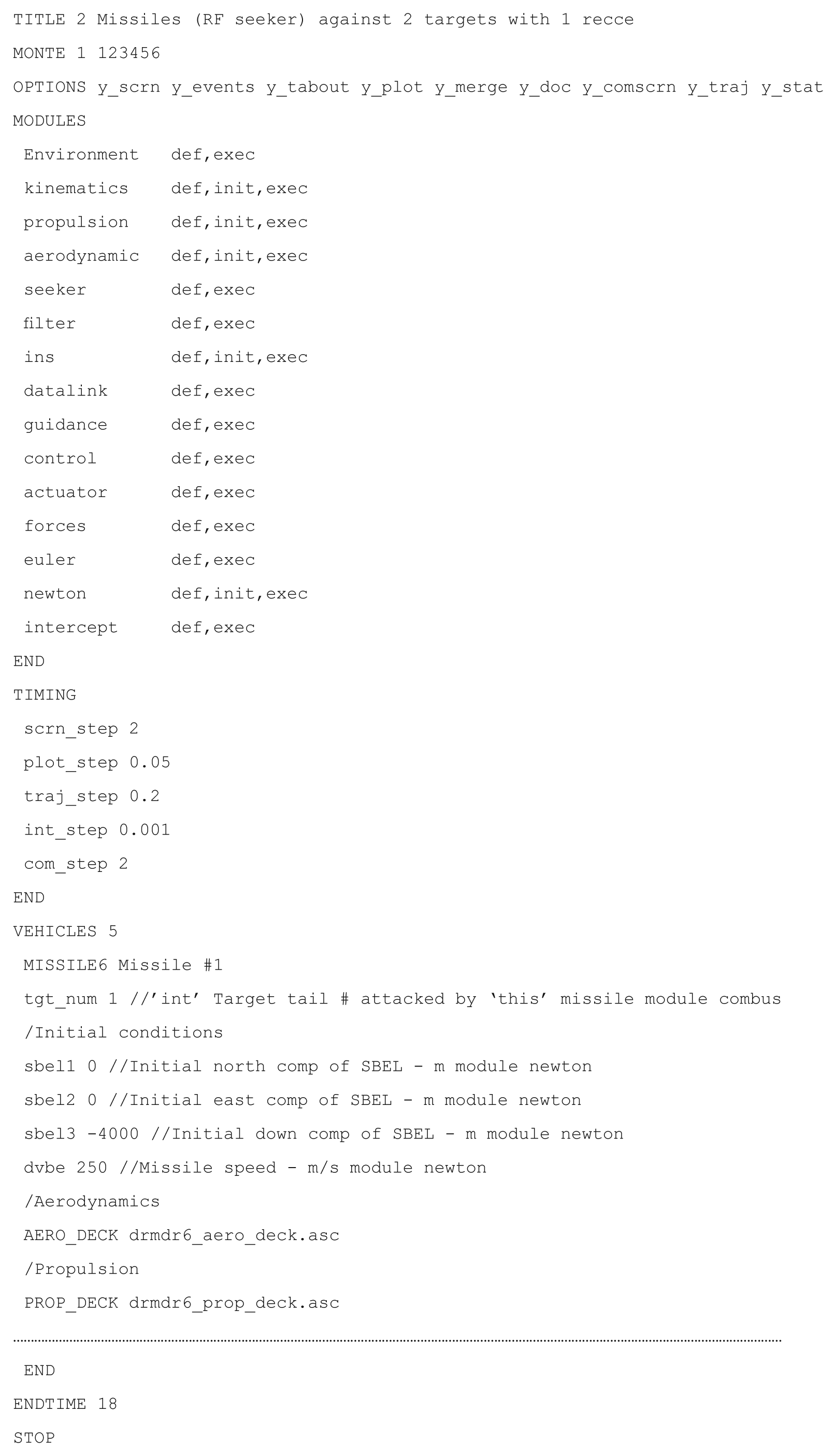
There should be only one input file that controls the simulation. It displays the run title, an option line for directing the output, the calling sequence of the modules, the sizing of the integration step and the initializing of the vehicle parameters. The integration step size should be variable. The aerodynamics and propulsion tables should be kept separate for safekeeping rather than being part of the source code. Their file names, given in the input file, would load the data decks into memory prior to execution. Multiple instantiation of the vehicle objects should be accomplished by simply duplicating the vehicle input data and changing selected variables as necessary.
The output control should be simple yes/no choices. An option line would provide output to the screen of the primary and secondary vehicles, together with the event messages that indicate their changing flight status. There should also be an option to archive the screen output to a file. Plot files as well as statistical data files would be written for individual vehicles and merged together for multi-vehicle displays. These output files should be compatible with the existing CADAC Studio for two- and three-dimensional plotting and statistical analysis.
The components of the vehicles should be mirrored by modules that model their features. Strict control of the interfaces will make the modules interchangeable amongst simulations. The modules should define these interface variables, execute integration of state variables and enable table look-up. Any vehicle changes that the user wants to make should be confined to these modules.
2.2 Multiple Encapsulated Vehicle Object
Each aerospace vehicle (be it missile, aircraft or spacecraft) should be built up from a hierarchy of classes, starting with the base class Cadac, followed by the equations of motion, and completed by the vehicle itself. Each vehicle is a C++ object with its data (aerodynamics and propulsion) and methods (modules) encapsulated. Run-time polymorphism should be used to sequence through the vehicle objects during execution.
2.3 Modularity of Vehicle Components
The modules, representing the vehicle components, should be public member functions of the vehicle classes. Their interfaces, the module-variables, would be stored in protected data arrays that are available to all modules of the vehicle object. During execution, the modules should define all module variables, make initializations, integrate state variables and conduct post-run calculations.
2.4 Event Scheduling
Just as aerospace vehicles transition though flight phases, the simulation should be able to sequence through such events. These events should be controlled by the input file without any code changes in the modules. Relational operators such as <, =, > would be applied to the module-variables and trigger the events.
2.5 Global Communication Bus
Because vehicle objects are encapsulated into classes, a global communication bus should enable the transfer of data. Each vehicle should be able to publish and subscribe to any of the module-variables.
2.6 Table Look-up
Table utilities should provide for one, two and three independent variable look-up. Tables must be stored in separate files and modifications easily accomplished. Simple syntax should make the table look-up easy to program in the modules.
2.7 Monte Carlo Capability
To automate the evaluation of random processes, a Monte Carlo methodology should be implemented. Distributions like uniform, Gaussian, Rayleigh, exponential and Markov should be identified in the input file by keywords. Stochastic output data must be written to files compatible with CADAC Studio for post-processing.
2.8 Matrix Utility Operations
The full power of C++ should be applied to matrix operations. Matrix utilities should be tailored to the specific needs of flight simulations and not burdened by C++ container classes. Efficient pointer arithmetic will speed up the execution and allow unlimited stringing of matrix operations.
2.9 Documentation and Error Checking
The module-variables, being the key interfaces between the modules, should be fully documented. The definitions provided in the modules should be collected in a single output file. The module-variables in the input file should also be documented with the same definitions.
Error checking should identify module-variables that have not been assigned the correct names or locations in the input file or the modules. Incompatible matrix operations should be flagged, as well as problems with opening of file streams. A variable should be displayed on the console that indicates the computational precision of the attitude calculations.
3. Architecture
These requirements can be satisfied with object oriented programming in C++. Hierarchical class structures, encapsulation of data and methods, run-time polymorphism, overloading of functions and operators, are all features used in CADAC++ to build a simulation environment suitable for flight vehicle synthesis.
CADAC++ programming follows the International Standard for C++ defined by the American National Standards Institute/International Organization for Standardization (ANSI/ISO) Committee in 1998 and implemented by most compilers like Microsoft Visual C++. Thus, portability is assured and low-cost operation is made possible.
Each requirement is now addressed separately, with particular focus on the classes that structure the features of CADAC++
3.1 Face to the User
The user friendly requirements are met with an architecture that enables easy use and modification of the simulations. The input file has all the features that control the execution: title, option line, module call, timing control and vehicle initialization.
The option line provides nine possible outputs. During run-time,
The user who wants to modify a vehicle component has only to deal with the corresponding module. The module contains all code and interfaces that define the components, carries out the table look-up and integrates the state variables. Re-use of modules for other simulations is facilitated by the strict control and detailed documentation of the interfaces.
As an example, let us look at the much abbreviated ‘newton’ module.
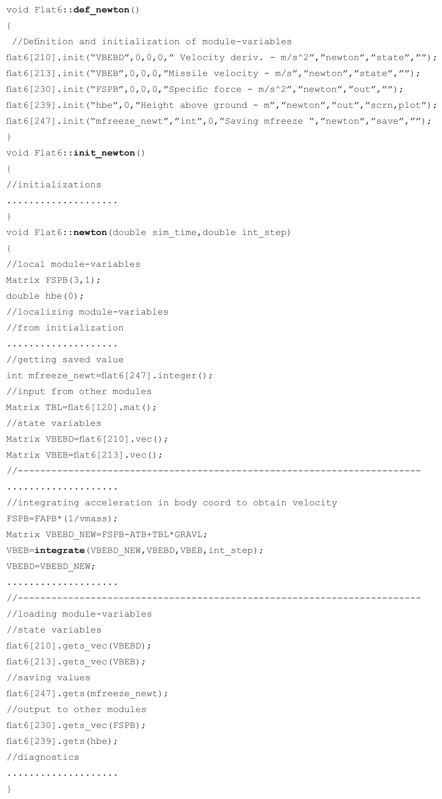
The module consists of three parts: the definition of module variables, the initialization and the integration. In
More detail of the modules is provided below under the heading Modularity of Vehicle Components.
3.2 Multiple Encapsulated Vehicle Object
The rewriting of CADAC was motivated by the unique feature of C++ allowing encapsulation of vehicle objects. Encapsulation means binding together data and functions while restricting their access. The aerodynamic and propulsion data are bound together with the table look-up functions and many other functions that support the missile and aircraft objects. In turn, these objects are created from a hierarchical class structure derived from the common abstract base class
This hierarchical class structure in CADAC depends on the particular simulation. For instance, the CADAC 6-DoF aircraft simulation consists of a single branch
The vehicle objects, declared by their respective classes, are created during run-time by the polymorphism capability of C++. Polymorphism (many forms, one interface) uses inheritance and virtual functions to build one vehicle-list of all vehicle objects, be they 6-DoF missiles, 3-DoF targets and recce aircrafts or satellites. At execution, this vehicle- list is cycled through at each integration step in order to compute the respective vehicle parameters.
The class
In
Then the global function
Now the
where
If the
Through run-time polymorphism any number of different vehicles can be called using the common pointer array of type
3.3 Modularity of Vehicle Components
A key feature of CADAC is its modularity, which reflects the component structure of an aerospace vehicle. Just as the hardware is divided into subsystems (such as propulsion, autopilot, guidance and control) CADAC simulations are broken into propulsion module, autopilot module, etc. This is extended to include non-hardware modules like aerodynamics, Newton’s and Euler’s equations of motion and environmental modules. This one-for-one correspondence ensures clean interfaces between the modules.
Each module is a pure virtual member function of the abstract base class
The calling sequence of the modules is controlled by their sequential listing in the input file
The structure
At creation of the vehicle object, at module initialization and at each integration cycle the
Then the initialization of the module takes place in
where
Currently, the terminal calls are not needed.
Data are transferred between modules by
The class
Other public methods of Variable govern the reading and loading of the module-variables inside a module. To make the module-variables local variables, the member functions
By convention, scalar variables are named with all lower-case letters, while upper-case letters designate matrices. Only 3 x 1 vectors and 3 x 3 matrices are permitted as module-variables.
The loading of the local module-variables into the protected arrays uses the member functions
Module-variables provide the sole data transfer between the modules of a vehicle object. For documentation they are recorded in sequential order in
3.4 Event Scheduling
As aerospace vehicles fly their trajectories, they may sequence through several events towards their destinations. Just think of rockets staging, airplanes taking off, cruising and landing and missiles passing through midcourse and terminal phases towards the intercept. Events in CADAC++ are interruptions of the trajectory for the purpose of reading new values of module-variables. They can only be scheduled for the main vehicle object. The maximum number of events is determined by the global integer
An event is defined in the input file
means, if the range to the target is less than 8000 m, the seeker is enabled. The supported relational operators are
The
Event data are read in
for each vehicle object and they are ’set‘ into
In the function
Event scheduling provides great flexibility to shaping the trajectory of an aerospace vehicle. However, as a design matures and the switching logic becomes well defined, the events can be scheduled in the module itself and any event scheduling in the
3.5 Global Communication Bus
Encapsulation by classes isolates vehicle objects from each other. However, this feature of C++ prevents direct communication between the vehicles. For instance, the missile object needs to know the coordinates of the target object in order for its seeker to track it. How can the missile get access to the protected target data?
In CADAC++ the global communication bus, called
Every vehicle prepares a data set of module-variables and publishes it to
Any vehicle can subscribe to the data set of any other vehicle. Utility methods enable the process.
The enabling global class is
Under the
Then, in function
Each packet has a data set of module variables stored in the array pointed to by Variable
The subscription of module-variables occurs in the modules. For instance, the seeker in order to track the target has to subscribe to the target position and velocity. First, the target ID is built from the string ’t‘ and the tail number of the target. Then
Knowing that the target position and velocity vectors are at offset 1 and 2, they can be subscribed
Now
The number of module-variables in the data set is unrestricted. If you are unsure of the storage sequence, you can find it by selecting
3.6 Table Look-up
Interpolating aerodynamic and propulsion tables is an important task in any aerospace simulation. Aerodynamic coefficients are usually given as functions of incidence angles and Mach number. Sometimes they are also expressed as functions of altitude and control surface deflections. Propulsion data are tailored to the type of propulsion system. For rocket motors, simple thrust tables may suffice. Turbojet and ramjet engines depend on throttle, Mach number and sometimes on incidence angles.
The more variables are used to describe the system, the greater the complexity of the table. Seldom is the dimension higher than three due to run-time considerations. CADAC++ supports table look-up schemes up to third dimension and interpolates linearly between the discrete table entries. It keeps the so-called ‘data decks’ as separate files so they can be properly protected as the need may arise.
The handling of the tables is accomplished by two classes,
The loading of the tables starts when the file
and the keywords
execute the code of the function
which picks up one of the
The extraction of the interpolated value occurs in the modules. The
which is overloaded three times for one, two and three independent variables. A typical example, taken from an ‘aerodynamic’ module of a two-dimensional table look-up, is
It returns the interpolated value. This call to
Additions and deletions of tables in the AERO_DECK or PROP_DECK are automatically adjusted during the loading of the tables. If a simulation requires data tables of a different type (e.g., antenna pattern) one has to do four things: (1) create an ASCII file with the data tables, (2) identify the file name by a keyword
3.7 Monte Carlo Capability
High fidelity simulations use random variables to model noise, disturbances and uncertain phenomena. If we make a single run, it represents only one realization of the total population of random variables. To do a complete stochastic analysis, many repetitive runs have to be executed, each drawing a different value from a distribution. This process can be automated and is referred to as the Monte Carlo capability of a simulation.
Randomized variables may be needed at initialization (e.g., seeker bias) or during the execution of the simulation (e.g., seeker noise). CADAC++ supports both. They are identified in the input file
To initiate a Monte Carlo run, the keyword
The stochastic variables, identified in
If there are initialization variables, a value is drawn from their respective distribution and held constant until it is re-initialized for the next trajectory. Module-variables identified by
The class
At every integration step, for each vehicle, the Markov noise function is called in function
This function downloads the Markov data from the
Because Markov noise is a first order correlation process, the current value depends on the previous value. Therefore, there is a provision in the
Stochastic analysis is an important aspect of the performance evaluation of any aerospace vehicle. CADAC++ support stochastic initialization for all vehicles, but reserves the Markov process for only the main vehicle. For post-run analysis, the stochastic data of the main vehicle are written to
3.8 Matrix Utility Operations
Modern programming uses matrix operations wherever possible to condense code and eliminate errors caused by coordinating equations. CADAC++ has a rich set of matrix operations which are public members of the class
The class
In the following examples, capitalized variables are arrays, lower-case names are either functions or scalars.
This example calculates the (3 x 1) acceleration vector
The next example calculates the 8 x 8 gain matrix of the filter:
And, finally, the 3 x 1 accelerometer vector error is determined by
Note the limitless possibilities of stringing together matrix operations.
Matrix variables are created by specifying their name and dimensions, e.g.,
The matrix utilities have a full suite of overloaded operators. The assignment operator requires a
The offset operator
3.9 Documentation and Error Checking
Self-documentation is an essential part of any simulation. Of primary interest are the variables that are used for input/output as interfaces between modules and those of particular interest for diagnostics. All are referred to as
CADAC error checking focuses in particular on the correct formatting of the
The class
This function, under the vehicle object scope, writes to
This function operates under the global scope. It uses the arrays of type
To flag violations of the one-on-one correspondence rule, both
During initialization, as the
A good description of a particular simulation is produced if the modules, the
4. Constructive Simulations
Constructive simulations have become the engineer’s major integration tool. With their realistic portrayal of the physical interactions between aerodynamics, propulsion, guidance and control they support concept studies, hardware integration tasks, flight testing and training. Specifically they enable the following:
Developing performance requirements. A variety of concepts are simulated to match up technologies with requirements and to define preliminary performance specifications.
Performing technology trade studies. Various subsystem are modeled and analyzed as they interact with other subsystems to determine the specifications that best meet the performance requirements.
Guiding and validating designs. Sensitivity studies are conducted to determine the optimal design parameters; models of subcomponents are tested as they interact with other parts of the system; overall performance is established.
Test support. Test trajectories and footprints are pre-calculated and test results are correlated with simulations.
Reduction in test cost. A simulation, validated by flight test, is used to investigate other points in the flight envelope.
Investigating inaccessible environments. Simulations are the most cost effective way to check out vehicles that fly through the Martian atmosphere or land on Venus.
Pilot and operator training. Thousands of flight simulators help train military and civilian pilots.
Practicing dangerous procedures. System failures, abort procedures, and extreme flight conditions can be explored safely on simulators.
Gaining insight into flight dynamics. Dynamic variables can be traced through the simulation and limiting constraints can be identified.
Integration of components. Understanding how subsystems interact to form a functioning vehicle.
CADAC, during its long history, has supported all of these tasks. It has been used to develop missile performance requirements, to conduct technology trades (airframe, propulsion, seeker, guidance and control), and to support flight test planning and data analysis. Air-to-air missile concepts have been integrated into air combat domes and into mission-level simulation frameworks like FLAMES®.
Not all CADAC simulations are at the 6-DoF fidelity, though high-fidelity modeling is required for delivery accuracy, hardware-in-the-loop and flight testing. However, during weapon conceptualization, lower fidelity 5-DoF or 3-DoF models often suffice or are mandated by the lack of detailed component data. These simpler simulations drop one or three of the attitude degrees of freedom. Most of the recent CADAC simulations are of 6-DoF fidelity, but some UAV, air-to-air and air-to-ground missiles are modeled at 5-DoF. All these simulations have the same CADAC++ framework. The distinction is reflected in the vehicle class structure and the associated modules.
For efficient use of constructive simulations, versatile plotting options and stochastic data processing must be available. CADAC Studio satisfies that need. Its history is as distinguished as that of the CADAC simulations. Originally developed for mainframes, then for VAXes and finally for PCs, it provides for interactive plotting, automated launch envelope and footprint generation and post-processing of Monte Carlo runs.
The plotting options consist of two dimensional traces and three dimensional trajectories either in a Cartesian grid or in longitude, latitude, altitude over the globe. A strip-chart capability plots up to 12 traces against time.
The SWEEP program of CADAC Studio automates the generation of footprints for air-to-ground missile and launch envelopes for air-to-air missiles. A single CADAC submittal will spawn trajectory runs against a target grid. Plotting options then generate carpet plots of selected parameters.
Monte Carlo runs draw from a variety of stochastic distributions for insertion of numerical values into uncertain parameters such as aerodynamic uncertainties, INS errors, seeker errors and wind gusts. CADAC Studio analyzes the output and generates CEPs, bivariate ellipses and mean values in the target or intercept planes with plots that also display the scatter points. Even the SWEEP program can be executed in the Monte Carlo mode to generate CEPs throughout the envelope or footprint.
CADAC and CADAC Studio provide a complete environment for constructive simulations. They have been used for bombs, missiles, UAVs, aircraft and spacecraft. Some recently developed simulations are summarized next.
5. Multi-use Examples
During the course of the CADAC++ development many simulations were built on the same framework. The modular architecture lends itself to multi-use applications. For example the environmental module is suitable for all simulations. The 6-DoF equations of motion over the WGS 84 10 or flat Earth apply to all corresponding simulations (Newton and Euler modules are the same). Seeker, INS, guidance and control laws can be shared where appropriate. With the strict enforcement of the interfaces between modules, the integration of an existing module into a new simulation is simplified.
Table 1 summarizes the currently active CADAC++ simulations. They cover the breadth of aerospace vehicles. Among the 13 simulations are two 5-DoF models, six over the flat Earth, and five over the elliptical WGS84 Earth. Most have Monte Carlo capability and use the U.S. Standard Atmosphere 1976; 11 some can implement a test atmosphere with winds aloft as well as Dryden-type turbulence. 12 The simulations are also distinguished by the type of vehicle objects they model. Some have just one object, while others have two or three. The first object is always the vehicle of primary interest. It determines the degree-of-freedom classification. It can morph into different configurations as indicated by the ‘+’ sign. The semicolon separates the objects. Each vehicle object can be instantiated multiple times making possible the engagement of many-on-many. Two simulations have been integrated into the mission-level FLAMES® framework: Long Range Strike Missile and Self Defense Missile.
CADAC++ Active Simulations
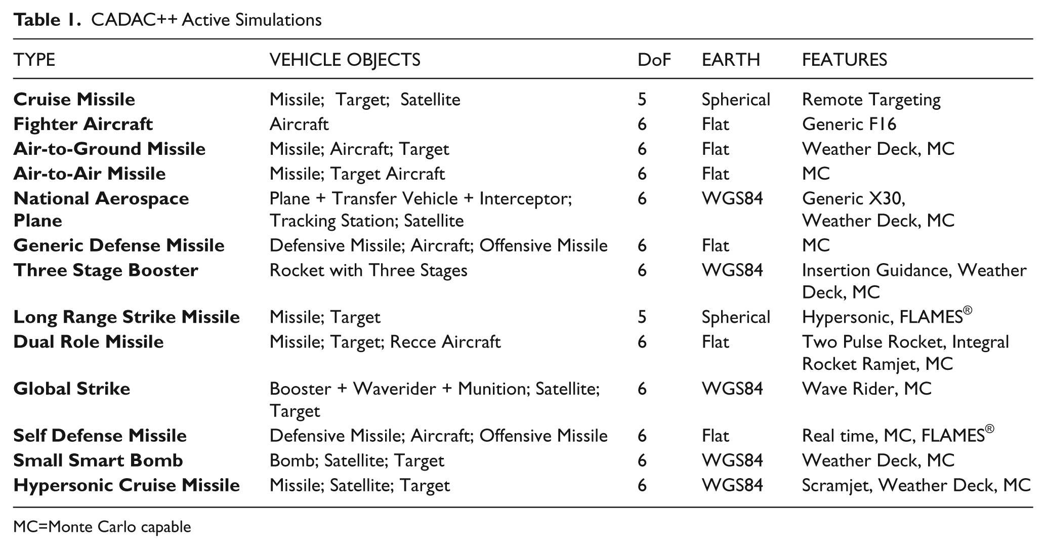
MC=Monte Carlo capable
Two simulations are presented as examples. The Three Stage Booster simulation represents a model of a rocket that can place a payload into low Earth orbit using the WGS84 equations of motions. The Generic Defense Missile simulation (which models three objects) represents a blue missile launched from a blue aircraft against an incoming red missile using the flat Earth equations of motions.
5.1 Three Stage Booster Simulation
This is a typical solid rocket delivery booster. It is controlled by thrust vector control (TVC) and reaction control system (RCS) but has no aerodynamic control fins. The autopilot uses accelerometer and rate gyro feedback from the inertial measurement unit (IMU) to steer the missile. During the first stage, a pitch program is executed while maintaining small incidence angles in the high dynamic pressure region. Stages two and three are under ascent guidance to meet the terminal insertion conditions. This guidance law implements linear tangent guidance for minimum fuel consumption.13,14 The onboard inertial navigation system (INS), updated by the global precision system (GPS) and a star tracker, provides the navigation states of the booster.
The class hierarchy of this simulation has only one branch, Cadac ← Round6 ← Hyper. ‘Round6’ models the 6-DoF equations of motion over the WGS84 Earth and ‘Hyper’ contains all the subsystems of the booster coded in modules (see Figure 1). The protected arrays of the classes are labeled
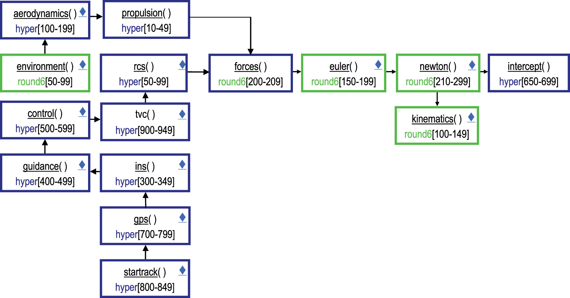
Modular architecture of the three stage booster simulation.
A typical trajectory is launched and places a payload at the suborbital conditions of 110 km altitude, 1.5° flight path angle and 6600 m/s inertial speed. Figure 2 was generated with the CADAC Studio Globe program.
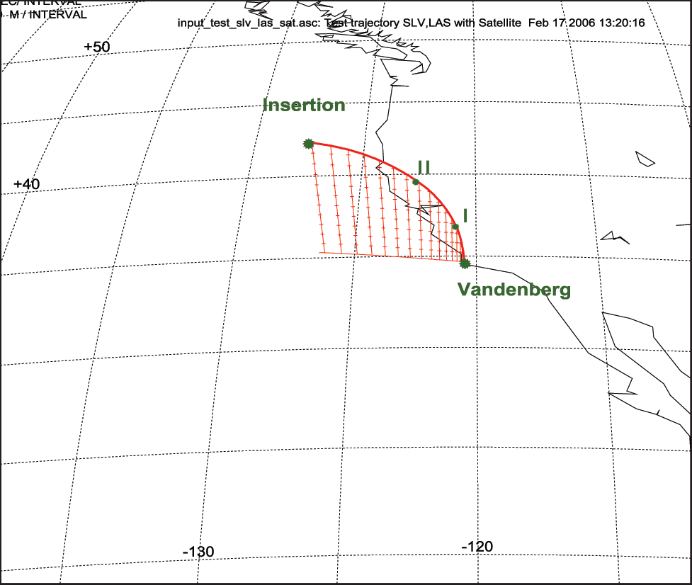
Ascent of the three stage booster and suborbital insertion.
To evaluate the performance of the booster the engineer requires the traces of many trajectory parameters. Some of them are plotted with CADAC Studio 2Dim and displayed in Figure 3.
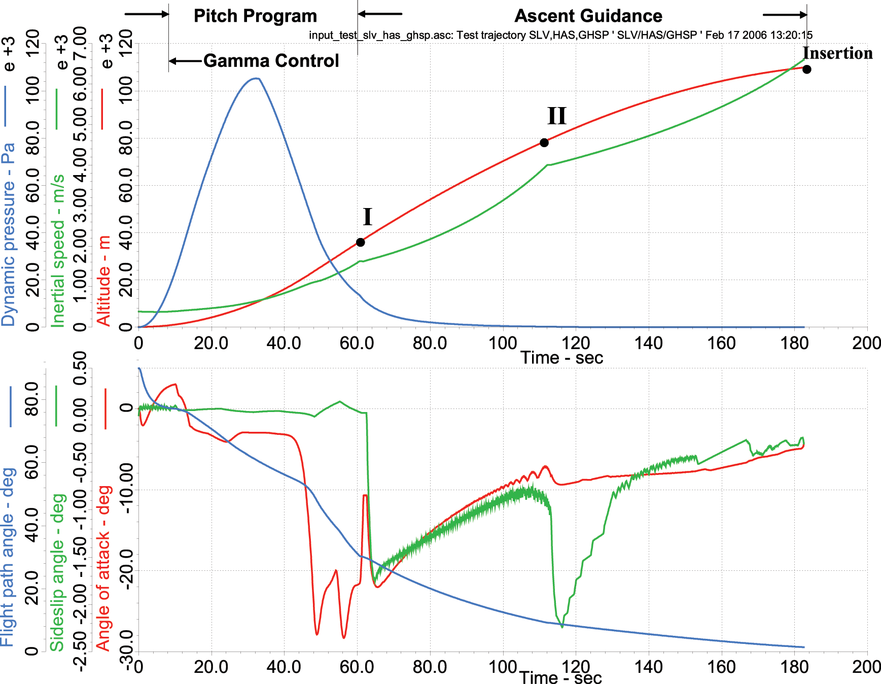
Trajectory parameters of the three stage booster ascent.
Note the dynamic pressure peak at 30 seconds into flight. The incidence angles are small during the peak to keep the structural loads within limits. Afterwards, the angle of attack increases dramatically to alter the flight path towards the insertion point.
This simulation makes use of the Round6 class common to all 6-DoF simulations over the WGS84 Earth. It uses the INS, GPS and star-track modules from other simulations. Only the aerodynamics(), propulsion(), guidance() and control() modules are specific to this application.
5.2 Generic Defense Missile Simulation
This simulation highlights the multiple instantiation of three vehicle objects. An aircraft launches a missile (blue) to intercept an attacking missile (red). The blue missile receives target updates during midcourse until its seeker locks onto the red missile for terminal homing.
The class structure has three branches. For the main missile object Cadac ← Flat6 ← Missile, for the red missile Cadac ← Flat3 ← Target, and for the aircraft Cadac ← Flat3 ← Aircraft. The modules are shown in Figure 4. Inside each object data flows through the protected arrays while across objects the data is provided by the communication bus ‘combus’ packets. Note that three levels of modeling fidelity are combined. The major focus of the analysis is on the blue missile. It is modeled in 6-DoF while the red missile is in 5-DoF and the aircraft in 3-DoF (though both, red missile and blue aircraft use the 3-DoF equations of motion).
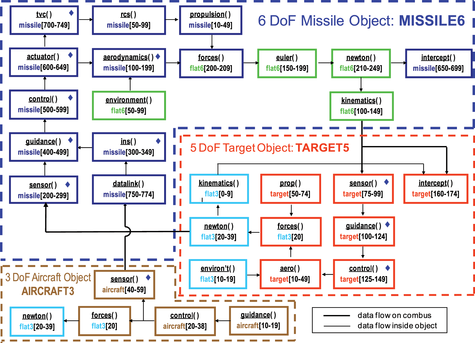
Modular architecture of the Generic Defense Missile simulation.
The multiple instantiation of the vehicle objects is demonstrated in Figure 5. The aircraft launches two defensive missiles against two incoming threat missiles. The graph was drawn by the 3Dim plotting program of CADAC Studio.

Two defensive missiles against two offensive missiles fly-out.
As an example of a typical Monte Carlo result, Figure 6 shows the impact points of the blue missile on the red missile intercept plane created by 100 MC runs. The generation of this graph is fully automated in CADAC Studio. The CEP and the bivariate ellipse are shown. It reveals a significant bias in the system due to guidance and control lags and limiters.
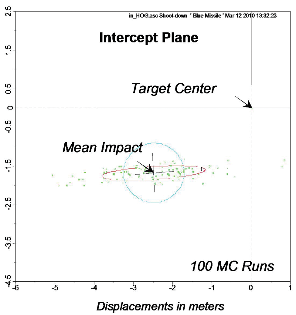
Impact of blue missile on red missile intercept plane.
The Generic Defense Missile simulation makes use of the common class Flat6 with its 6-DoF equations of motion over the flat Earth. Several modules of the blue missile are shared with other simulations. These include modules such as rcs(), tvc(), actuator(), ins() and sensor(). The modules aerodynamics(), propulsion(), guidance() and control() are specific to the Generic Defense Missile.
These are just two examples of the family of CADAC++ simulations shown in Table 1. Other simulations also demonstrate the commonality made possible by the class structure and modularity of the CADAC++ architecture.
6 Summary
The conversion of CADAC from FORTRAN to C++ is essentially complete. During the ten years since the switch has been made, several simulations were updated and new models created. CADAC Studio also experienced modifications to make it compatible with the C++ output. The new code has been applied to various US Air Force projects and found to be invaluable for concept explorations, technology assessments and mission-level studies.