
Abstract
Unmanned aerial vehicles (UAVs) are remotely piloted or self-piloted aircrafts that can carry cameras, sensors, communication equipment and other payloads. Tiltrotor UAVs provide a unique platform that fulfills the needs for ever-changing mission requirements, by combining the desired features of hovering like a helicopter and reaching high forward speeds like an airplane, which might be a force multiplier in the battlefield. In this paper, the conceptual design and aerodynamical model of a realizable small-sized Tiltrotor UAV are presented, and the linearized state-space models are obtained around the trim points for airplane, helicopter and conversion modes. Controllers are designed using tracking optimal control method and gain scheduling is employed to obtain a simulation for the whole flight envelope. An interactive software infrastructure is established for the design, analysis and simulation phases, based on the theoretical concepts.
1. Introduction
Aerial vehicles have proved their usefulness in military (combat, deployment of units, patrolling, surveillance, reconnaissance, etc.) and civil areas (transport, search and rescue, fire-fighting, etc.) of application for a century, while enhancing their capabilities over time, and fulfilling the ever-changing mission requirements. The low speed restrictions of airplanes and high speed limits of helicopters have made their operation areas different from each other. Although a lot of effort has been spent on combining the advantages of these types of aircrafts into one platform, with the hope of eliminating disadvantages, using forms such as tiltwings and tailsitters, none of the previous approaches has been successful enough to go into production until the realization of tiltrotors.
A tiltrotor aircraft combines the vertical lift capability of a helicopter with the speed and range of a turboprop airplane. 1 As the name implies, a tiltrotor aircraft uses tiltable rotating propellers for lift and propulsion. For vertical flight, the proprotors are angled to direct their thrust upwards providing lift. In this mode of operation, the aircraft is essentially identical to a helicopter. As the proprotors are slowly tilted forward the aircraft gains forward speed, with the blades eventually becoming perpendicular to the ground. In this mode, the wings provide the lift, and the wings’ greater efficiency helps the tiltrotor achieve high speeds. In straight flight mode, the aircraft is essentially a turboprop aircraft.
In this study we aim to assert an initial conceptual design for a small-sized Tiltrotor UAV, examine its dynamics, and determine the control strategies and requirements for a realizable model. The geometrical design of the aircraft is realized by modeling all of the components individually, and then combining them together in order to form the full aircraft model. The aerodynamical model is based on the geometrical model, and it is used to simulate the aircraft in flight, with the purpose of obtaining the forces and moments generated using blade elemental theory. 2 Trim points are calculated for navigation states that encapsulate the entire flight envelope. Analytical and numerical linearization techniques are utilized in order to obtain the linearized state-space models around the trim points. The stability characteristics of the aircraft are examined from the linearized models, with the analysis of eigenvalues. An optimal tracking controller 3 is designed to be able to control the Tiltrotor UAV for the whole flight envelope. The transitions between the trim points are achieved through the gain scheduling method.
The main contribution of this work is the introduction of a new type of UAV, Tiltrotor UAV, with design considerations and analysis results. Unlike its manned predecessors, its small size and capability of transitions between flight modes through tilting the body itself characterizes the unique nature of Tiltrotor UAV; this allows faster transitions and higher levels of stability in the helicopter mode. In general, airfoil dynamics are utilized up to the stall angle in modeling airplanes and helicopters. Owing to Tiltrotor UAV’s genuine conversion method, a lookup table method based on instantaneous Reynolds number is asserted in modeling airfoil out of the stall angles.
2. Conceptual design
The conceptual design of Tiltrotor UAV (Figure 1) is realized according to the available airplane and helicopter models, with the purpose of combining the desirable and eliminating the undesirable features. The design phase is accomplished through the following steps.
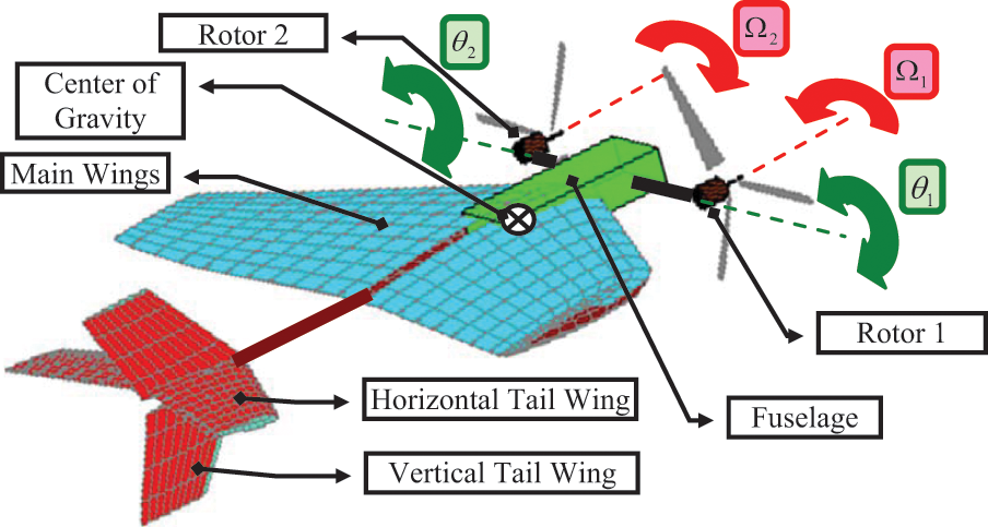
Conceptual design of Tiltrotor UAV.
-The fuselage is the main component of the Tiltrotor UAV, holding all parts together with payloads, avionics and electrical systems.
-Wings are fixed symmetrically at the sides of the fuselage, providing lift at forward speeds. A dihedral design is used through the wingtips in order to increase stability of the rolling motion.
-Tail wings, both horizontal and vertical, are fixed at the back of the aircraft in order to increase stability by providing the aircraft pitch and yaw moments.
-Tiltrotors are stationed at the front side of the fuselage. These powerplants are like propellers on an airplane, which provide thrust with a tilt angle. The control variables, both rotational speeds
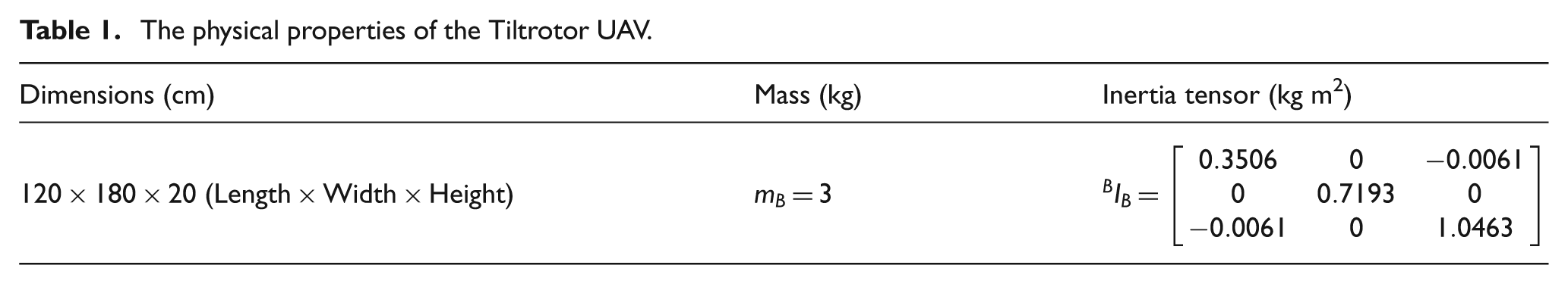
Tiltrotor UAV, having the physical properties given in Table 1, is designed with the graphical user interface (GUI) programs explained in Section 7. The transitions between the flight modes are accomplished by changing the rotational speeds of the propellers and the angular positions of the rotors, as shown in Figure 2. As both of the rotors are tilted forward progressively, the orientation of the fuselage becomes parallel to the Earth’s surface for level flight.
The physical properties of the Tiltrotor UAV.
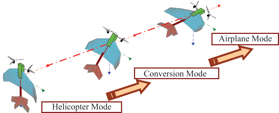
The flight modes of Tiltrotor UAV.
3. Modeling
The main components of Tiltrotor UAV, environmental effects and gravity are modeled as shown in Figure 3.
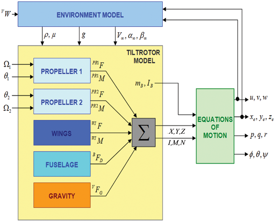
General model of Tiltrotor UAV.
3.1. Environment model
The medium that the aircraft experiences has many variables such as temperature, pressure, density, viscosity, speed of sound, and gravitational acceleration. These variables are calculated based on the environment model (atmosphere and gravity models) according to the aircraft’s position in the world. Our atmosphere model utilizes the ISO standard atmosphere model 4 and calculates air pressure, air density, air viscosity, and speed of sound according to the altitude of the aircraft with reference to the mean sea level. In the gravity model, the gravitational acceleration is calculated using the WGS84 (World Geodetic System—84) model.
3.2. Equations of motion
The equations of motion are obtained from the motion formulas of Newton and Euler: 5
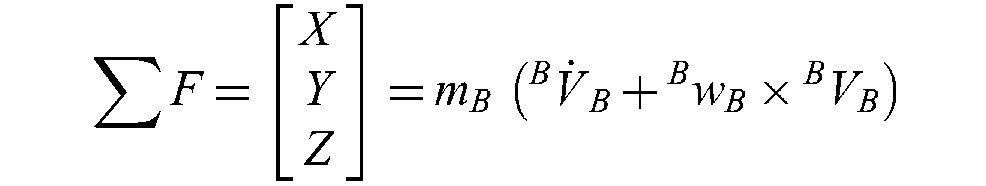
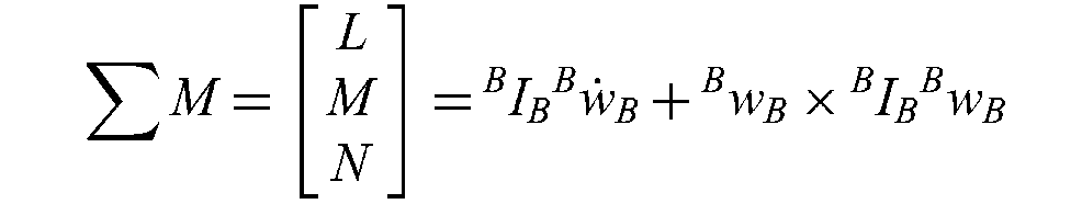
Equations of motion takes gravitational acceleration (g) from the environment model, physical properties
3.3. Tiltrotor UAV model
The Tiltrotor UAV model adds up the forces and moments generated from the fuselage, wings and propellers according the center of gravity of aircraft, resulting in net forces and moments
3.3.1. Fuselage model
The fuselage experiences forces in the direction opposite to the motion, proportional to the magnitudes of velocities
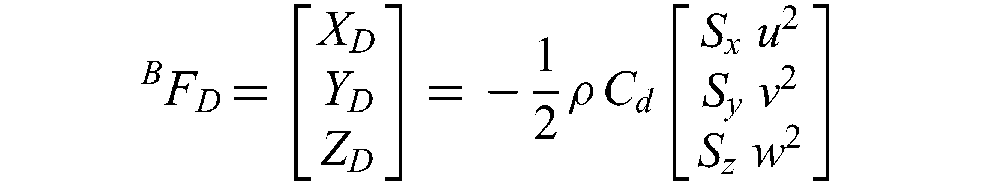
due to the capability of Tiltrotor UAV to move in any direction.
3.3.2. Airfoil model
Airfoils are the elemental components of wings and propeller blades, which provide lift due to their aerodynamic shapes. Together with the type (i.e. NACA0012), chord length (c), airflow speed (V
AF
), angle of attack coming from propeller and wing models, the air density and viscosity (ρ, ±) obtained from the environmental model constitute the inputs for the airfoil model. Sectional aerodynamical coefficients (lift, drag, moment) of airfoils defined for the unit span of the wing
2

and angles of attack which are smaller than the stall angle. The coefficients for angles greater than the stall angle are obtained by the interpolation of the results obtained by Sheldahl. 6 Both calculated and interpolated values of coefficients constitute a lookup table for a range of airspeeds and the full envelope of angles of attack in ±π range (Figure 4):

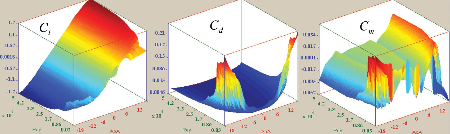
Aerodynamic coefficient surfaces for
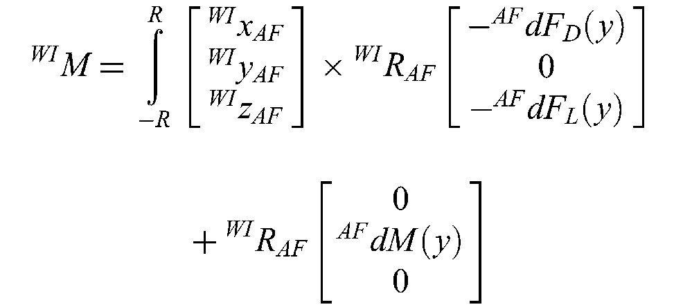
The lift–drag forces and moments acting on the infinitesimal length airfoils are calculated with respect to the following equation, according the schematics shown in Figures 5 and 6:

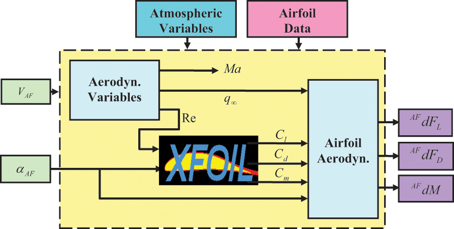
Airfoil model.
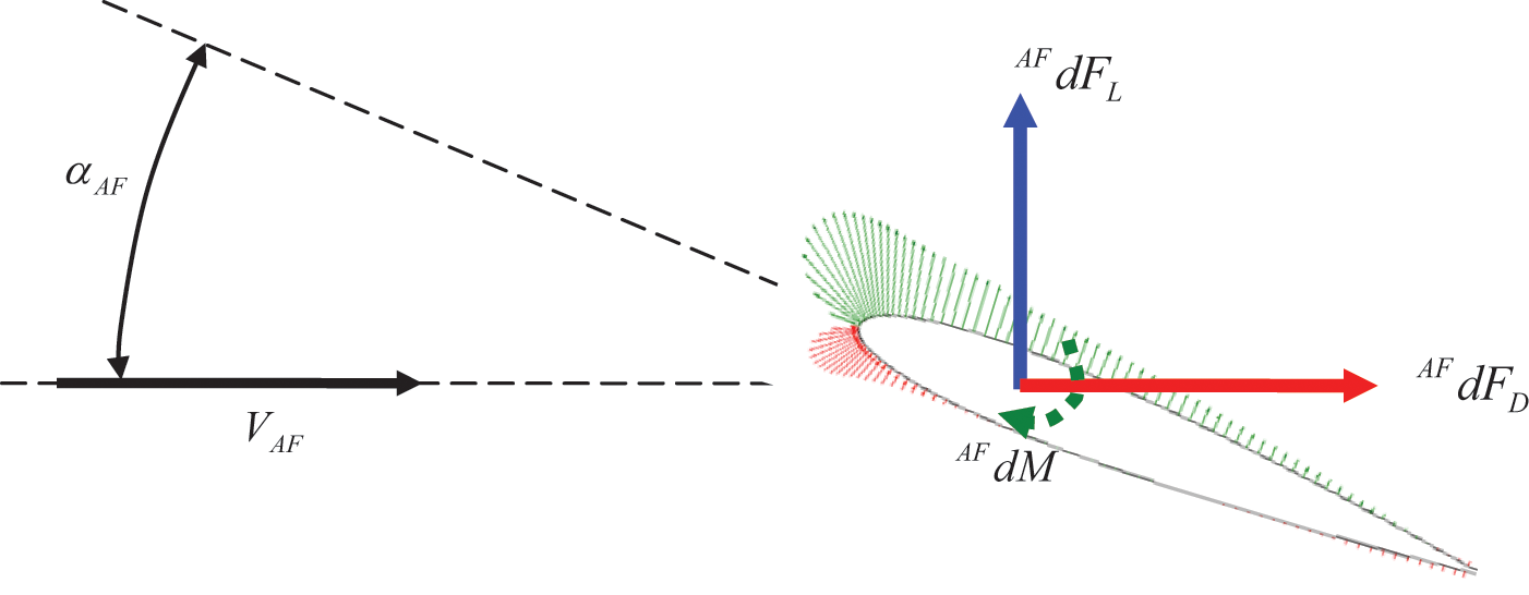
Airfoil aerodynamics.
3.3.3. Wings model
The main wing and tail wings (horizontal and vertical) of the Tiltrotor UAV are modeled in a similar fashion, since the building blocks of these components share the same structure. The inputs of the wings model are the airfoil properties (airfoil type and chord length), wing structure (airfoil pitch angles,

in order to obtain net forces and moments acting on the wings, respectively.
3.3.4. Propeller model
The Tiltrotor UAV has two propellers, located on either side of the fuselage. Each propeller has a power plant, with the tilt angle,
The airspeed
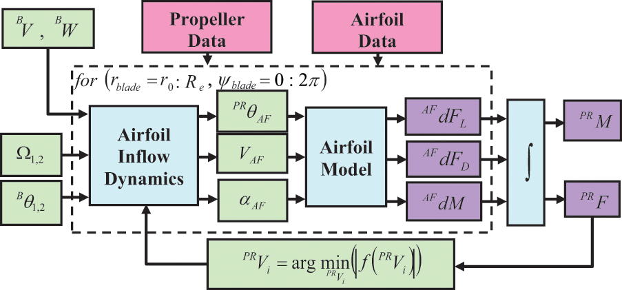
Propeller model.
Propellers suck air as they rotate according to Newtonian mechanics, satisfying the conservation of momentum and energy laws. In momentum theory for propellers, the rotor is conceived as an ‘actuator disc’, across which a sudden increase of uniformly spread pressure is established. With the application of conservation of momentum and energy principles for the air mass traveling through the actuator disc, 8 an equilibrium state of the thrust of the propeller and the air inflow is constituted. The values of these variables are obtained by solving a minimization problem, which uses a generalized pattern search (GPS) algorithm: 9
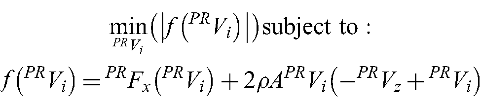
where
In order to obtain net forces and moments generated by the propellers, the averages of the forces acting on blades are calculated over a period
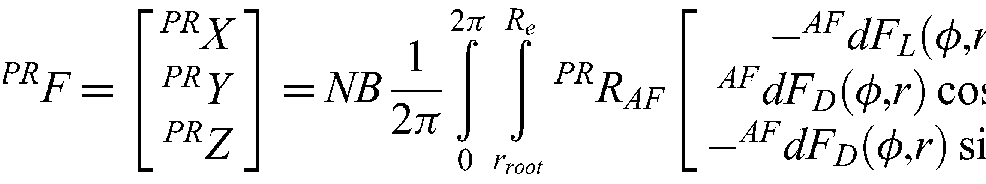
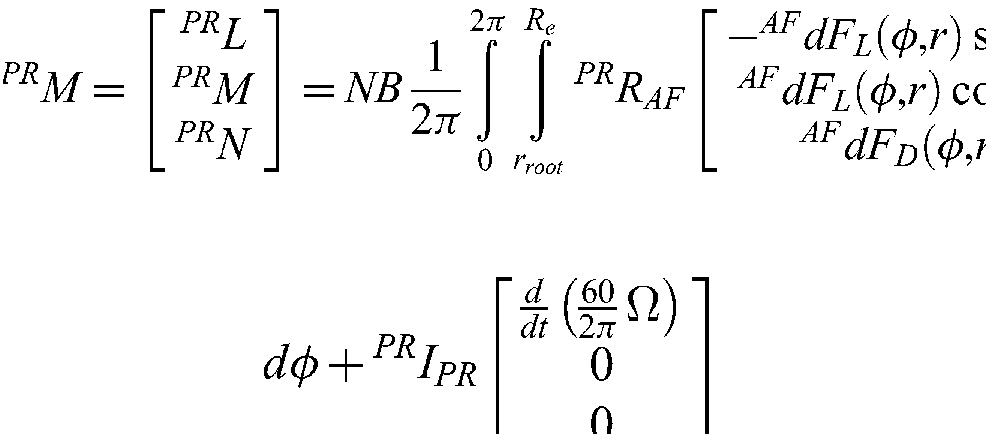
where NB is the number of blades,
4. Stability analysis
4.1. Trimming
The state variables are divided into two groups of aerodynamical variables
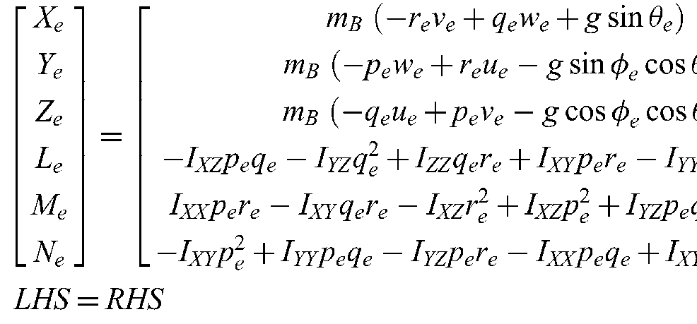
Then the trim condition requires the equation LHS = RHS to be satisfied. The trim algorithm for level flight starts with assigning lateral variables to zero and initialization of longitudinal variables according to navigational variables. The feasible search regions for the pitch angles of the fuselage (θ), tilt angles of the propellers
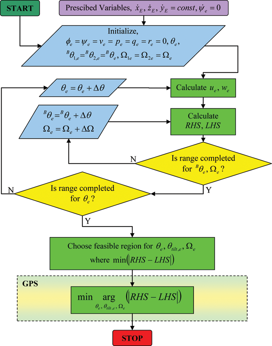
Trim point calculation algorithm for level flight.
4.2. Linearization
The equations of motion are separated according to analytically differentiable (F1, algebraic expressions in the equations of motion) and numerically differentiable (F2, forces and moments in the equations of motion) parts as

As F1 is differentiated analytically, the derivative of F2 is calculated using a two-sided backward–forward differencing method, because of the complex dynamics of the Tiltrotor UAV model, which are obtained numerically in the simulations. Using Taylor’s expansion
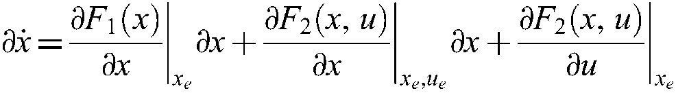
for the trim points, yields the linearized system’s equations with the elimination of higher-order terms:

where
4.3. Stability analysis
The stability analysis of the Tiltrotor UAV is carried out with the examination of eigenvalues of the linearized model for different trim conditions. Figure 9 shows that the Tiltrotor UAV exhibits similar characteristics to manned tiltrotor aircraft such as V-22 and XV-15, in helicopter and airplane modes. The instability of the Tiltrotor UAV increases at the conversion mode, because of the need to change the orientation of the fuselage.
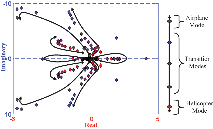
Eigenvalues of Tiltrotor UAV according to flight modes.
5. Control system design
The control system design is based on the tracking optimal control method, 3 which guarantees the stability of the closed-loop system using the linearized models at the trim points, in order to follow the commands of the navigation system. Bryson’s rule 10 is used to attain the weighting values of Q and R, which are positive symmetric matrices.
The optimization problem
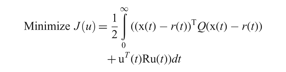
subject to
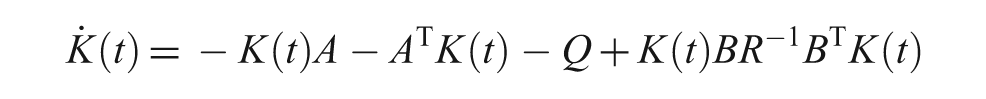
and reverse time equation
The optimal control inputs,

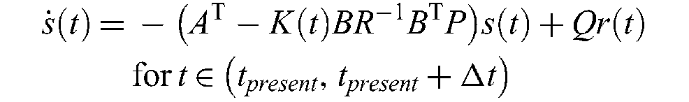
Hence, when the desired state vector r(t), which is the next trim point to be reached, is assumed to be fixed for a small time interval Δt, the state tracking errors are minimized by applying optimal control inputs u*(t), where x(t) is obtained by forward-time integration using the current trim point as the initial state of the state equation. Also, s(t) and K(t) are obtained by reverse-time integrations, with
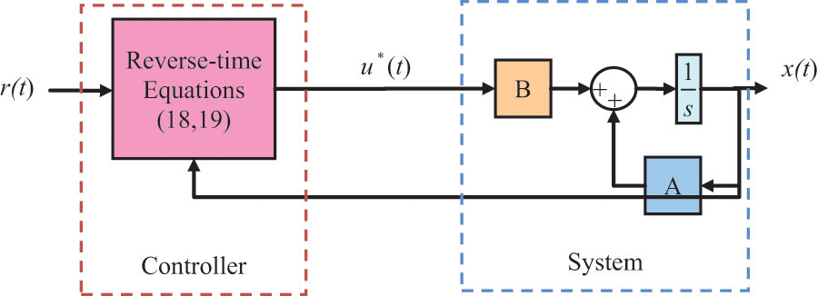
Tracking control system design for Tiltrotor UAV.
6. Graphical user interfaces
The theoretical background established in Sections 2, 3, 4 and 5 has been integrated into airfoil analysis, part designer, UAV designer and control system design and simulation programs, using Matlab 7.6.0 (R2008A) Graphical User Interface. The method of design and analysis of a UAV requires sequential usage of these interconnected programs as shown in Figure 11.
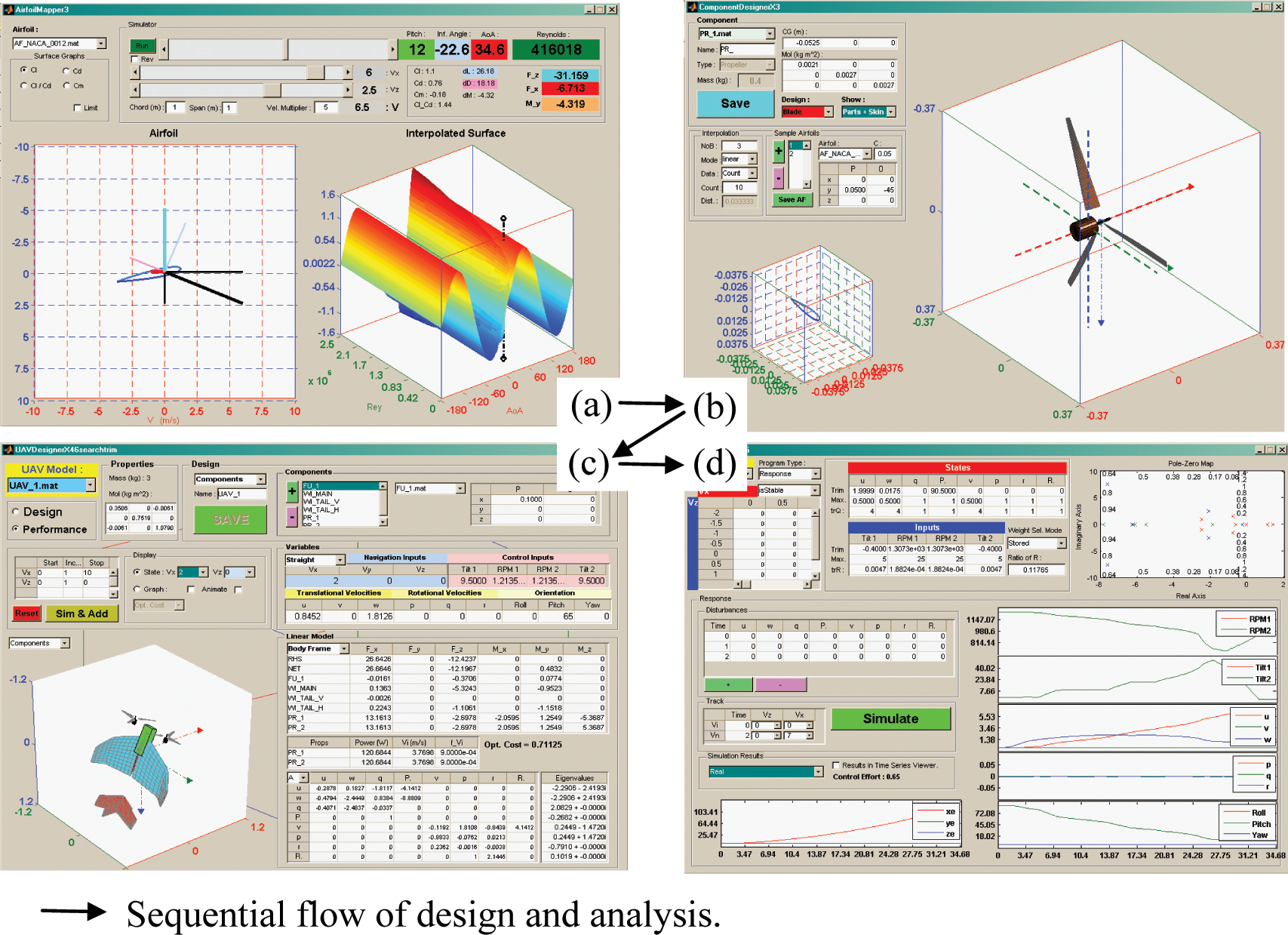
(a) Airfoil analysis; (b) part designer; (c) UAV designer; (d) control system design and simulation programs.
6.1. Airfoil analysis program
The airfoil analysis program uses the results of the XFOIL
7
simulations for various airfoil types, and composes three-dimensional graphs of aerodynamical constants
6.2. Part designer program
The part designer program provides an interactive asset in designing the physical features of the parts of the Tiltrotor UAV. Different types of parts can be designed such as the fuselage, main wing, horizontal tail wing, vertical tail wing and propellers independently by assigning dimensional, physical and geometrical quantities.
6.3. UAV designer program
The UAV designer program provides an interactive way of constructing the UAV by combining the fuselage, wings and propellers at the desired locations and orientations. This program also features the simulation of the UAV model through various aerodynamical conditions, by finding the trim points and linearized models automatically.
6.4. Control system design and simulation program
The control system design and simulation program allows navigation commands and disturbances of the environment to be set interactively. After adjusting the parameters of the controller, a simulation is performed and the time series of the state variables are displayed for observation.
7. Flight simulation results
The characteristics of the Tiltrotor UAV are examined by obtaining trim conditions (16 × 9 = 144 trim points) for a range of navigation states;
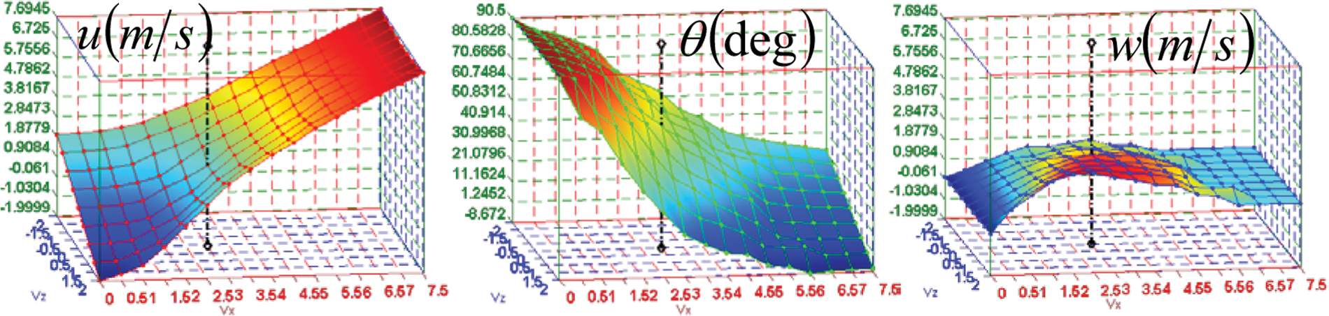
Trim state transitions of Tiltrotor UAV.
Considering trim inputs, as the Tiltrotor UAV enters airplane mode, tilt inputs of the rotors make them perpendicular to the surface of the Earth as expected. Figure 13 shows that the rotational speeds (RPM) of the rotors decrease together with the power requirements. The decline in the power requirements by reaching airplane mode from helicopter mode stems from the fact that the lift source is only the propellers for hover, and the main wings for level flight. When the airplane mode is achieved, trying to reach higher speeds will make the inflow of the propellers increase, with the result that the propellers cannot sustain thrust for small RPMs. This problem could be resolved by the choice of a variable-pitch propeller, or more tilted propellers at the expense of losing hover performance. Figure 13 shows that the Tiltrotor UAV would require much power during ascent and helicopter mode, and less power in descent and airplane mode, as expected.
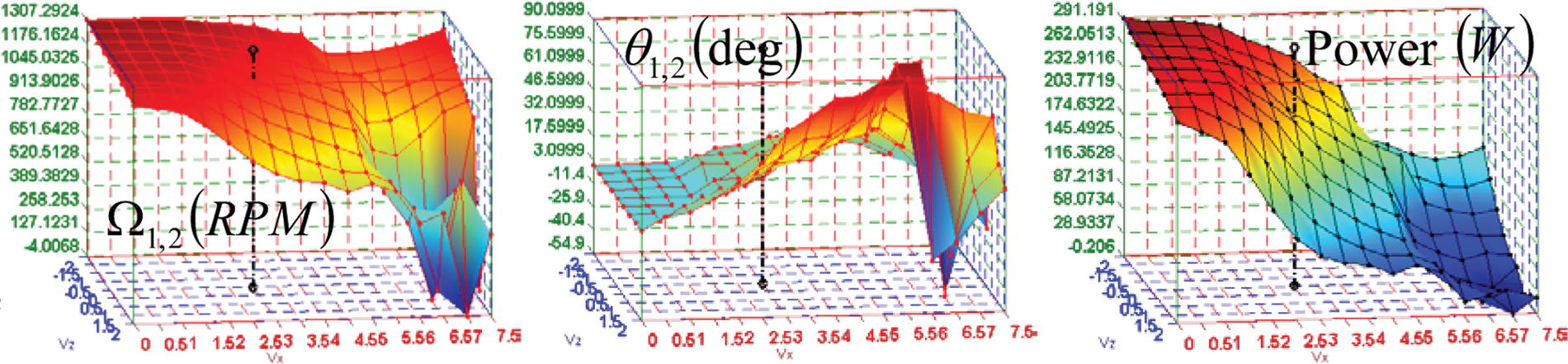
Trim input transitions of Tiltrotor UAV.
The Tiltrotor UAV has poor stability characteristics as an overall flight envelope criticism (Figure 14). Provided that the helicopter mode is unstable, the aircraft becomes even more unstable in the conversion mode. However, as the speed increases further, letting the wings operate in the more efficient regions of operation, the Tiltrotor UAV achieves stability by entering the airplane mode.
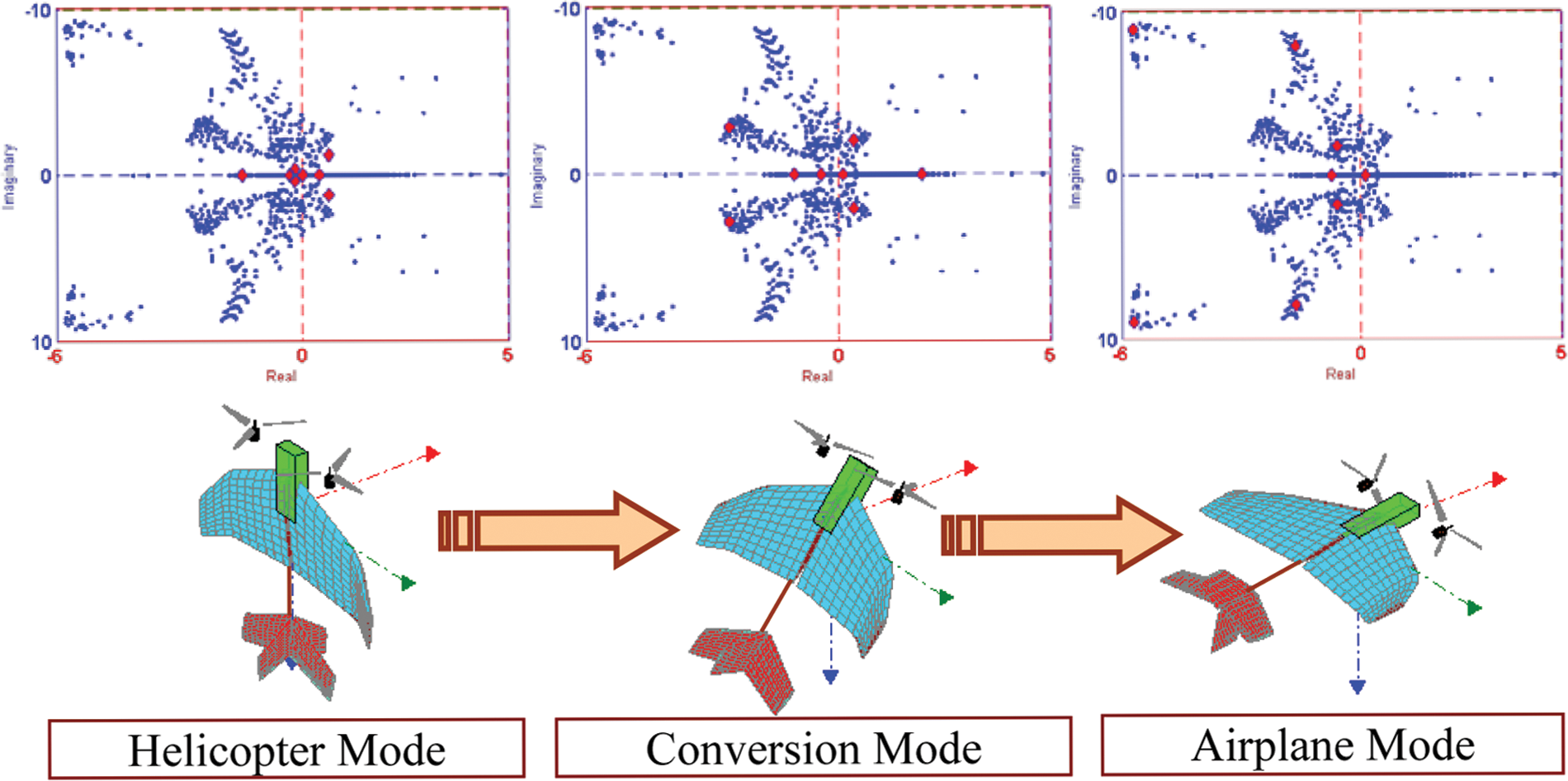
Stability characteristics of Tiltrotor UAV.
In order to evaluate the controller, the Tiltrotor UAV is commanded to reach 7 m/s of level flight (airplane mode) speed from hovering (helicopter mode), with 1° of roll disturbance in the time interval
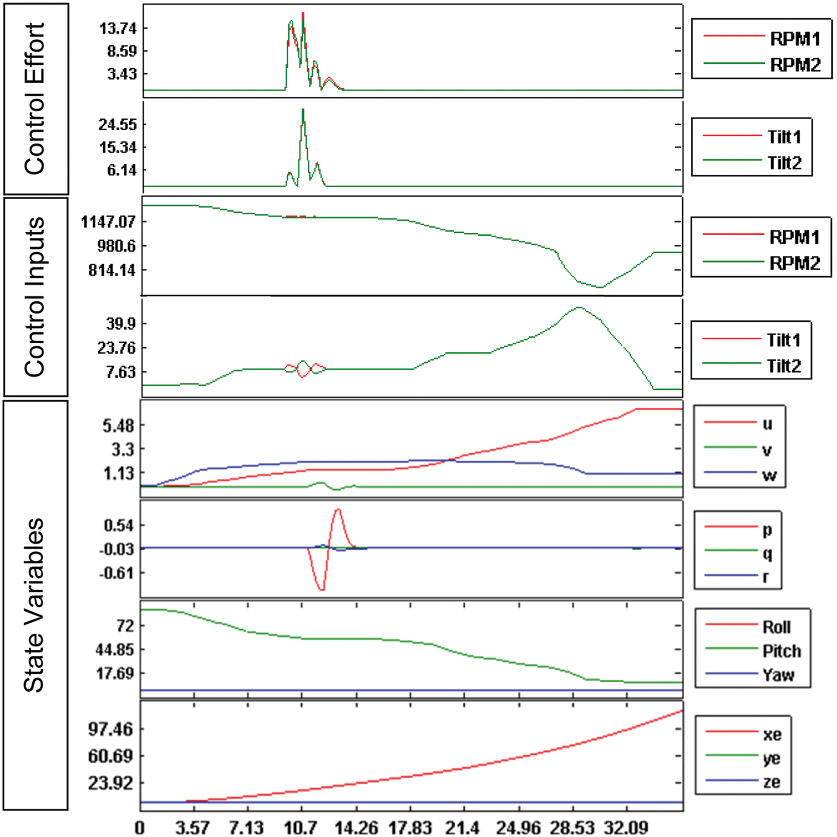
Simulation of the transition of Tiltrotor UAV from helicopter to airplane mode.
Roll disturbance is chosen to be able to observe the changes in the control inputs more clearly, which can be caused by a gust or a false measured gyro output, where a differential change of RPMs and tilt angles of the rotors are expected to be applied by the controller to suppress the effects of disturbance. In the case of a pitch disturbance, the rotors would be expected to tilt simultaneously. Similarly for a yaw disturbance, the expected control inputs would be differential RPM changes. Hence, roll disturbance poses a more challenging situation, when compared with pitch and yaw disturbances.
8. Conclusion
The conceptual design, modeling, stability analysis, control system design and simulation of the Tiltrotor UAV has been accomplished through dedicated programs with the purpose of combining the desirable features and eliminating the undesirable features of helicopters and airplanes, which might be a force multiplier in the battlefield.
The asserted model of the aircraft showed similar characteristics to its manned ancestors V-22 and XV-15. The Tiltrotor UAV has the capability of hovering like a helicopter and reaching high speed and obtaining efficient straight flights like an airplane. The full flight envelope of the Tiltrotor UAV encapsulates both helicopter and airplane models as shown by Leishman. 12 In the conversion mode, the fuselage is aligned passively with the tilt of rotors due to a weathercock effect, resulting in degradation of stability characteristics, which is different to its manned ancestors. Although the Tiltrotor UAV demonstrates an unstable nature in the conversion mode, it is observed that the control system stabilizes the aircraft inherently even in the presence of disturbances, at the expense of excessive consumption of control efforts.
A hand-launched fixed-wing mini UAV has up to 150 parts, which is relatively easy to maintain compared with a helicopter UAV of the same category, which has at least four times as many parts. The Tiltrotor UAV has only two tiltable rotors as moving parts, which makes it easy to maintain like a fixed-wing UAV, with the advantage of vertical take-off and landing capability like a helicopter. A serious drawback of the Tiltrotor UAV is the instability of the conversion mode, which requires large control efforts. Therefore, Tiltrotor UAV should be operated in the conversion mode only for conversion purposes between the helicopter and the airplane modes, as quickly as possible. For operational purposes, by mounting a payload gimbal to the top of the fuselage between the rotors, visual intelligence can be gathered effectively in the helicopter and airplane modes, but the conversion mode cannot be used as an operational mode for reconnaissance owing to Tiltrotor UAV’s unstable nature in this mode, which will result in larger oscillations in attitude and degrade image quality.
Simulation results have proved that a trade-off exists between the performance of the helicopter and the airplane mode, which cannot be achieved simultaneously. Although, the choice of a pitch-variable propeller would improve performance for both of the modes, this would require a more complex design and additional control surfaces.
The analysis has shown the requirements for very fast actuators for the tilt and RPM changes, which are not easy to achieve in the real world. Although slower controls perform well under certain conditions, this makes the Tiltrotor UAV more vulnerable to disturbances. These challenging requirements resulted from the unstable characteristics of the Tiltrotor UAV, which can be reduced with additional control surfaces such as a tail stabilizer or a free-wing design, which results in a more complicated design.
The simulation and modeling tools developed in this study revealed the dynamics of the Tiltrotor UAV, pointing out the requirement for a revision of the conceptual design, before prototyping. Programs prepared for the design and analysis of the Tiltrotor UAV allows rapid modeling of new concept aircraft types, providing simulation and analysis capabilities of versatile aerodynamical conditions, including operation in out-of-stall boundaries. These capabilities will be used in designing an agile-maneuvering aircraft and its control system as a future work.
Footnotes
Funding
This research received no specific grant from any funding agency in the public, commercial, or not-for-profit sectors.