
Abstract
Using Tactical Environment Simulations as part of simulation systems or real systems; increases the reality and quality of the applications, reduces development time, increases interoperability and reusability of systems. Tactical Environment Simulations are utilized by integrating them into applications which can have a wide variety of requirements; so, they are generally customized to meet specific requirements of the applications. Apart from most of the Commercial-Off-The-Shelf (COTS) tools that are used directly, Tactical Environment Simulations are often provided as Application Frameworks which contain readily available simulation models, middleware, extension points and a tool set to ease customization and integration. In this paper, the requirements and a design overview for an easily extensible, customizable and integrable, High Level Architecture (HLA)-based Tactical Environment Application Framework are provided. After defining the requirements and giving an overview of design, an Application Framework that realizes the defined system is also explained.
Keywords
1. Introduction
The importance and usage of advanced simulation systems is continuously increasing in many application areas. Therefore, reusability and interoperability of simulation systems is getting more and more critical to decrease costs and complexity. A number of architectures such as Distributed Interactive Simulation (DIS) 1 , High Level Architecture (HLA),2–6 and Test and Training Enabling Architecture (TENA) 7 are developed to meet the reusability and interoperability needs. However, as these are only general purpose HLAs, it is still a necessity to develop Application Frameworks on top of them as an infrastructure to provide domain specific services (such as Geographic Information System services), reusable components and tools. Such Application Frameworks aim to increase product development efficiency and reusability in order to decrease the cost of the final products.
In this paper, the requirements and a conceptual design of a HLA-based Tactical Environment Application Framework that can be used in a wide range of simulation applications are defined. Proposed Tactical Environment Application Framework contains various tools and generic models in addition to a generic simulation middleware and a group of services. Section 2 contains introductory information about Tactical Environment Simulations. Section 3 explains related works. Section 4 summarizes the requirements of a Tactical Environment Application Framework. Section 5 contains the high level design of a Tactical Environment Application Framework that meets the requirements given in Section 4. Section 6 explains the realization of the proposed framework and gives performance considerations. Section 7 covers the conclusions and the future work.
2. Tactical environment simulations
A tactical environment is the entire natural and manmade artifacts that an entity or a person can interact within a tactical context. The natural part of the tactical environment consists of the geographic environment and the environmental conditions such as rain, snow, wind, etc., while the manmade part consists of buildings, roads, bridges, vehicles and systems such as weapons or radar. Depending on the context, other involving factors such as signals transmitted by the systems can be part of the tactical environment.
Almost in every simulation application, the environment and other entities are required to be modeled as supporting simulations. For example, in a helicopter flight simulator, geographic environment, weather, atmospheric conditions and Electronic Warfare (EW) systems that the helicopter will interact with shall be modeled in addition to the helicopter model. Simulation applications that focused on providing this simulation environment are commonly named as “Tactical Environment Simulation” or “Synthetic Environment Simulation” or just “Environment Simulation”. We will use the name Tactical Environment Simulation (TES) in the rest of the paper.
In some cases, TES systems are integrated with real systems to provide a pseudo environment that real systems will interact with for test and training purposes.8,9 In addition, TES systems can also be used in the analysis of the behavior and the evaluation of effectiveness for algorithms such as threat evaluation and weapon assignment algorithms. 10
3. Related work
There are two different approaches to provide a TES for a system. First naive approach is to develop a new domain specific TES system from scratch. Widely known Joint Theatre Level Simulation (JTLS) 11 and Joint Conflict and Tactical Simulation (JCATS) 12 have their own built-in TES systems.
The second approach is to reuse a Commercial-Off-The-Shelf (COTS) TES system. There are various available COTS tools in the market like Lockheed Martin’s NxTES, 13 CAE’s Strive 14 or MAK’s VR-Forces 15 that aim to provide a tactical environment for related simulation systems.
With the benefits of reusing components for software development, 16 using available COTS components as much as possible for building products should be the preferred approach instead of developing them from scratch.
The requirements that the TES systems are expected to meet often vary according to the needs of the specific application that tactical environment will be used for. Because of these variances, it is not easy to provide TES systems as black box applications. A TES system is generally served as an Application Framework with readily available components that enable addition of new ones and customization of the existing ones in order to create specialized environments.
This paper is about our own Tactical Environment Application Framework that we developed in context of a distributed training simulation project. Before developing our own Tactical Environment we evaluated several COTS tools and found that they did not meet the requirements of our project. The project was a joint distributed simulation that requires development of a TES system which provides EW models with higher fidelity than theatre level models (such as those provided in JTLS) and tactical level models (such as those provided in JCATS). The other key requirement was to be able to create scenarios with thousands of entities and execute these scenarios up to four times faster than real time. This requirement forced development of models with lower fidelity than entity level simulation systems such as radar or flight simulators.
4. Requirements of a tactical environment application framework
In this section, requirements of a Tactical Environment Application Framework that are gathered during development of a large scale distributed training simulation are explained. The requirements that the framework should satisfy can be divided into five categories, as follows.
4.1. Standards compliancy
Standards compliancy is necessary for simulation systems to increase reusability and interoperability. As stated before, some architectural standards/frameworks such as DIS, HLA and TENA are developed to enable interoperability and reusability of simulation systems.
HLA is an IEEE (1516) and NATO (STANAG 4603) standard developed for simulation systems and widely used all around the world, so it is essential for the Application Framework to be compatible with HLA.
In addition to HLA compliancy, the Application Framework shall ease integration to systems based on different simulation architectures like DIS and TENA. HLA is a de-facto standard for now and HLA compliancy is sufficient to meet current requirements, but it does not mean that it will be always true. The Application Framework shall be designed such that it will be customizable to make it to work with the standard simulation architectures other than HLA.
4.2. Load distribution
Generally, TES Systems are designed as federates that join to HLA-based simulation applications that are called “federation” in HLA context. This architecture enables isolation of the TES from the rest of the simulation and running more than one simulation entity (radar, aircraft, missile models, etc.) in one federate for scalability.
The Application Framework shall provide load distribution capabilities for large scale simulations where performance of a single computer is not sufficient to execute the whole TES system.
4.3. Application independence and generic entity models
The Application Framework shall provide an application domain independent generic environment to enable the development of the TES systems for different application domains.
The Application Framework shall be designed with flexibly to serve different application areas such as system integration, algorithm evaluation and analysis, operational analysis, doctrine development, concept verification, etc. The Application Framework shall enable development of TES systems for both of Live, Virtual and Constructive simulations.17–19
There are some common simulation entities which are required by different simulation systems. The Application Framework shall provide a model library which contains readily available simulation entities. Each of the simulation entities shall be easily utilized in different simulation systems depending on the nature of the system.
The Application Framework shall also enable the addition of new models to the library and behavior customization of predefined ones. The model library shall provide predefined models such as:
Platform models (air, ground vehicles, etc.),
Radar systems,
RF jamming and deception systems,
Electronic Support Measurement/Direction Finding (ESM/DF) systems,
EO/RF guided missiles and seekers,
Passive warning systems such as Missile Warning System (MWS), Laser Warning Receiver (LWR), Radar Warning Receiver (RWR),
Active self-protection systems (chaff, flare, etc.),
Link and communication systems,
C2 systems,
Surface to Air Missile (SAM) systems,
Ballistic weapons.
The Application Framework shall also provide autonomous behavior for predefined models to enable creation of Computer Generated Forces (CGFs).
Models shall not rely on a specific deployment configuration, they shall use publish/subscribe communication model provided by the Application Framework to exchange data with other models. Each TES federate will be a container for multiple models. With this, the decoupled TES system can be dynamically distributed more than one federate.
The Application Framework shall provide necessary tools and Application Programming Interfaces (API) for developing, testing, packaging and reusing library models. Requirements of necessary development tools are given in Section 4.5.
4.4. Common applications for simulation environments
The Application Framework shall provide the necessary tools for the rapid development of the TES systems. These applications can be listed as:
Reference Models database which stores reference entities;
Scenario Editor which enables scenario preparation in a map-based environment;
Scenario Player which executes scenarios.
4.4.1. Reference models database
The Application Framework shall provide an entity database and a management application for it that enables defining parameters, properties and relations of simulation entities that can be used in various simulation scenarios. The Application Framework shall enable creation of complex simulation entities by composing multiple simulation entities. For example, it should be possible to define a fighter aircraft that carries various systems such as radars, missiles, etc.
4.4.2. Scenario editor
The Application Framework shall provide a Scenario Editor to create scenarios in a map-based visual environment by using the entities defined in Reference Models database. Similar Scenario Editor Applications are provided in Lockheed Martin, NxTES Tactical Environment Simulation, 13 Halle and Berner 14 and MAK Technologies, VR-Forces. 15
Scenario Editor shall support adding Reference Model entities to the scenario by assigning them to friend, foe, neutral, ally or civilian forces. Scenario Editor shall provide basic capabilities such as changing entity parameters, defining autonomous behavior for entities and combining entities to form complex entities. It shall also provide tools and capabilities to ease creation of logically consistent, efficient scenarios. For example, Scenario Editor shall provide Radar Coverage and Line of Sight (LOS) analysis tools to help find optimal positions of scenario entities that will be located on the map during scenario creation. Scenario Editor shall also enable creating scenarios at different geographical locations of the world by using various atmospheric and weather conditions (rain, snow status and density, cloud status, wind velocity, etc.).
4.4.3. Scenario player
The Application Framework shall provide a map-based generic Scenario Player that will enable running scenarios defined with the Scenario Editor Application on a distributed environment. Similar Scenario Player Applications are also provided in Lockheed Martin, NxTES Tactical Environment Simulation, 13 Halle and Berner 14 and MAK Technologies, VR-Forces 15 just like the Scenario Editor Application.
The Scenario Player Application shall provide basic player capabilities such as play, pause/resume, stop the scenario execution and setting the scenario execution speed (1×, 2×, 4×, 8×, etc.). It shall provide tools and applications to visualize the scenario execution in 2D maps and system scope screens. In addition, the application shall provide 3D visualization (normal, UV and IR) of the geographic environment, weather and atmospheric conditions, scenario entities and events.
The Scenario Player Application shall also provide record/replay capability to enable After Action Review (AAR) and the evaluation of previously executed scenarios.
The Scenario Player Application shall be compliant with the HLA 1516 standard to enable distributed scenario execution.
4.5. Support tools
The Tactical Environment Application Framework proposed in this paper is not intended to provide just a generic TES system; the main idea with this framework is to provide an environment for rapid development of different TES systems. In this context, the framework shall provide a set of support tools in addition to generic TES components and applications.
4.5.1. Rapid application development tools
The Application Framework shall provide various application development tools that will increase efficiency of the design, development, integration and testing steps of simulation development that are defined in Federation Development and Execution Process (FEDEP). 5 Actually these tools are not part of the TES system and the end product; they will be used during development of the TES system. The required tools are explained below and ordered by their related FEDEP steps.
The first tool is an Object Model Definition tool that will be used for the design and development of the Federation Object Model (FOM) and Simulation Object Models (SOM). 4 Basic entities of system are defined in the “Perform Conceptual Analysis” step of FEDEP by utilizing various templates and frameworks such as BOM 20 and KAMA. 21 The Object Model Definition tool will be used for defining the FOM of the system and the SOM of the models/federates by using conceptual model. The SOM definition shall be in terms of defining publish/subscribe mappings between Object Model elements and models/federates.
The second tool is an Automatic Code Generation tool that will generate application code of the FOM. This tool is essential if the FOM of the project changes frequently during the development due to using an iterative development methodology like Rational Unified Process. 22 Generating common/boilerplate code will be useful in both decreasing the cost of change and avoiding programming errors, and in this way, it will encourage the development team to refactor and redesign to increase product quality.
The third tool is a debugging tool which enables pausing of the simulation and the inspection of the current state of shared simulation objects.
The fourth tool is a test framework that enables writing isolated unit tests and also high level integration and qualification tests. The test framework shall provide capability to mock 23 the behavior of other generic components to provide an isolated test environment for the “model under test”.
The fifth tool is a performance monitoring tool that shall be capable of monitoring and displaying resource consumption of individual Simulation Models. Outputs of this tool can be used for finding bottlenecks in the simulation execution.
4.5.2. Record/replay tool
The Record and Replay tool shall be capable of recording the scenario execution and replaying for debriefing or AAR purposes. This tool will also be used by the Scenario Player to meet the record/replay requirements.
5. High level design of HLA compliant tactical environment application framework
The high level overview of the Application Framework that meets the requirements defined in previous section is given in Figure 1. The Application Framework consists of four logical packages: a “Simulation Environment”, a “Model Library”, a “Support Tools” group, and a “Utility Package”. Application Framework uses HLA 1516 as the infrastructure as shown in Figure 1.
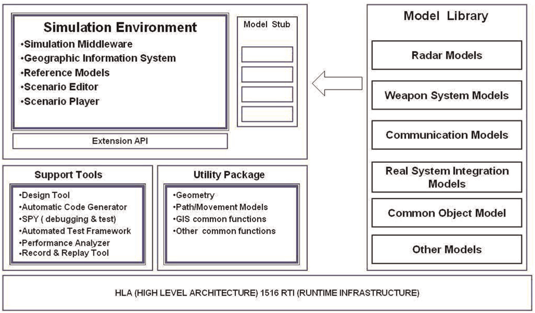
High level overview of tactical environment application framework.
The rest of this section explains the modules of the Application Framework.
5.1 Simulation environment
The HLA enables interoperability and reusability of simulation systems by setting rules for simulation system and participants, 2 standardizing communication interface between participants and simulation infrastructure, 3 and defining a template for Object Models that will be used for data exchange. 4 The HLA standard also defines a recommended process to support the development and execution of simulation systems. 5 Understanding the HLA and implementing HLA compliant simulation systems is difficult and needs a long period of learning.
To overcome the complexity of HLA development, a general solution is to use an abstraction framework that simplifies complex HLA Runtime Infrastructure (RTI) API. HLA abstraction API enables isolation of RTI API interaction codes to avoid scattering of API calls/callbacks among the simulation application. By localizing the API interaction, simulation system can be adapted to future standard or infrastructure changes by changing only the abstraction framework. There are available tools in the market like MAK VR-Link 24 that provides such an HLA RTI abstraction.
The Simulation Environment contains a Simulation Framework that provides an HLA RTI abstraction layer. This Simulation Framework forms a generic basis for developing Simulation Models by providing a Simulation Engine and a Distributed Object Layer as shown in Figure 2.
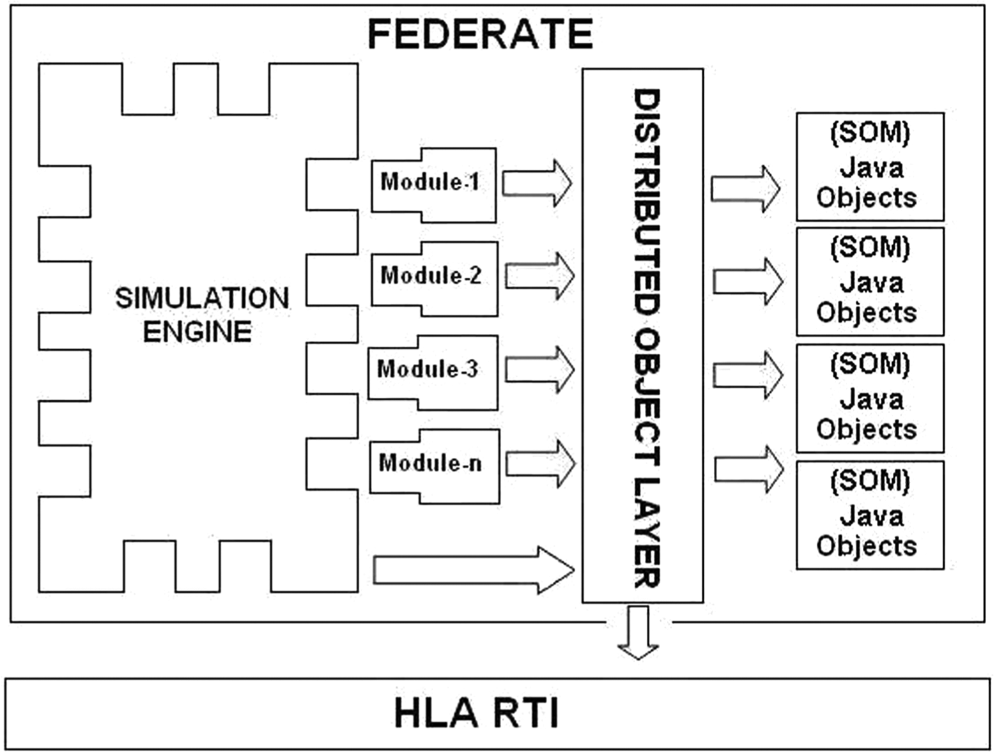
Simulation framework.
A federate utilizing Simulation Framework can execute more than one module by using the Simulation Engine and the Distributed Object Layer (DOL) components. Modules can be Simulation Models (model concept will be explained in the Model Library section), integration bridges, evaluation, test or performance measurement tools, etc.
The simulation systems that use this Simulation Framework can easily be integrated to other systems that use HLA and other architectures such as Data Distribution Service (DDS),9,25 DIS or TENA by developing simple bridge modules that provide data exchange between systems. More detailed information about Simulation Framework is given by Gökdoğan, Özkan and Çelik. 26
5.2. Model library
Component Oriented Software Engineering (CBSE) 16 proposes decomposing software systems into functional components with well-defined interfaces and objectives for reusability. According to CBSE, components can contain other components, be a part of other components and have independent versions. Reusability is not just about the executable software components itself. A component’s design, unit and functional tests and documentation such as requirement specifications should be packaged with the component to increase reusability level. Thus, a component can be reused in another system as a complete software package.
Architectural concepts defined in the HLA standard are very similar with the concepts of component technologies. Each participant in HLA is called a “federate” and each federate is connected to other federates via an Object Model Definition which is called the SOM. The definition of “federate” overlaps with the concept of “Component” while the SOM definition overlaps with “Interface of Component”.
Like most of other component technologies, HLA does not have any restriction on content and internal behavior of developed components (federates). In our case, there can be thousands of EW simulation models (radars, missiles, platforms, etc.) participating to a distributed simulation execution session. HLA does not dictate any rules for the distribution of EW simulation models to federates for our case. Developing and deploying each EW simulation model as a separate federate does not violate the HLA standard; however, this solution is not effective in terms of scalability and performance. Another alternative is having more than one simulation model in one federate as in MAK Technologies, VR-Forces 15 and Lees, Logan and Theodoropoulus. 27
As shown in Figure 2, the Simulation Framework allows running more than one “module” in one federate by using the Simulation Engine and the DOL. Each simulation entity is modeled as a module and named as a “Simulation Model” or shortly a “Model”.
When a scenario is executed, models are loaded and distributed to federates that are utilizing the Simulation Framework. Model distribution to federates is performed according to a predefined execution configuration.
A model package contains the model definition and keywords that identify the model, version information, a SOM definition, actual behavior and user interface codes as shown in Figure 3.
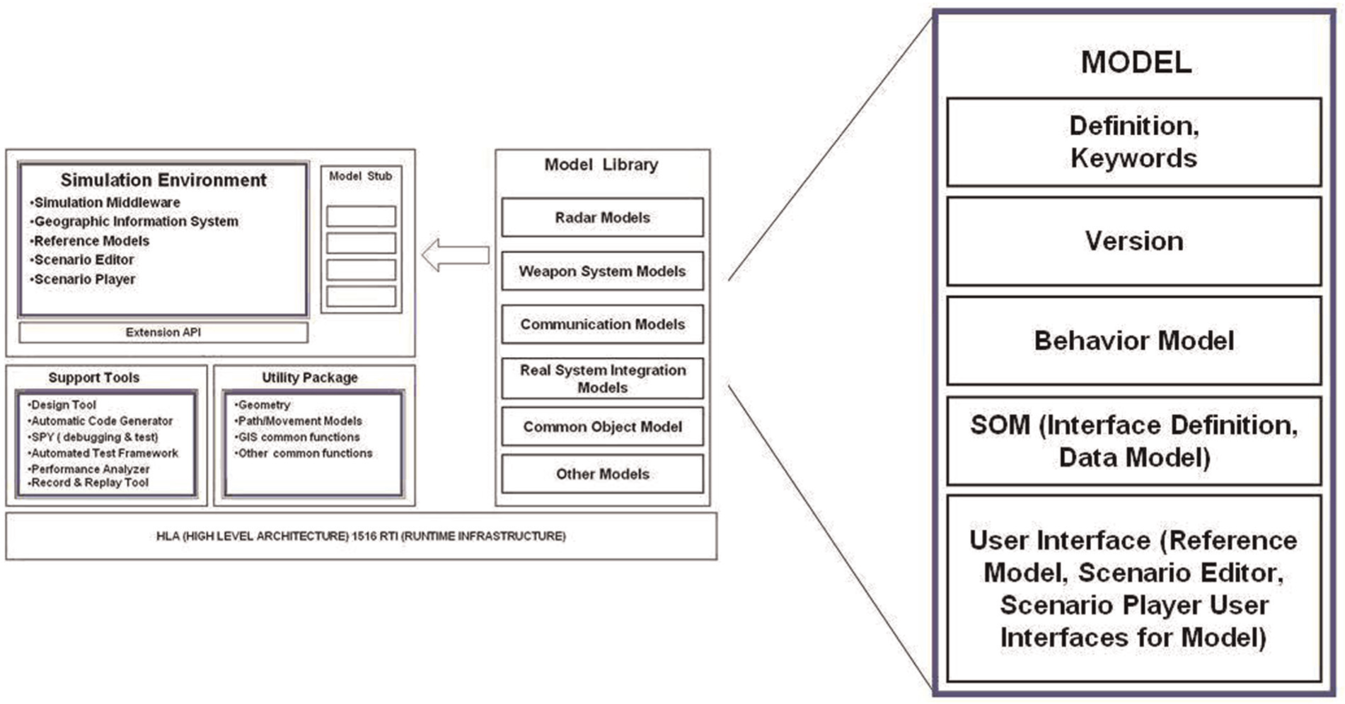
Details of a model.
In addition to supporting execution of multiple models in one federate, a federate can also be configured to execute only one model. For example, a simulation model which contains a complex, high fidelity model and consumes a lot of resources can be assigned to a single federate for load partitioning.
Just like a federate’s SOM, a data exchange abstraction model is required for models to enable independent development and foster reusability. Instead of introducing a new concept, a model can be assumed as a small federate and the SOM definitions can be used to express a model’s data exchange interface. Each model has its own SOM definition as shown in Figure 3.
The HLA standard mandates all exchange of FOM data among federates occurs only via RTI. Models shall obey to this rule just like to all other rules defined for federates. A mandatory artifact that shall be developed for HLA simulations is the FOM of simulation system. The FOM can be developed by combining the SOM definitions of federates/models as defined in FEDEP.
5.3. Geographical information system
The Application Framework uses Geographical Information System (GIS) to support working on different areas of the world or with imaginary maps. The Application Framework supports 2D tactical display and 3D visualization of terrain data provided by GIS. GIS also provides capabilities such as:
LOS queries,
Standardized symbol display,
Tactical shape visualization,
Air zone visualization,
System (e.g. radar and ESM) coverage area visualization.
GIS support is a nice capability that makes the application more realistic and capable, but it is not so easy to integrate GIS capabilities to a distributed simulation system. For example, one of major problems is mapping simulation entities with GIS objects. Generally GIS systems are event based, so changes in simulation objects shall be converted to GIS events to stimulate the system. We developed an Asynchronous Object Layer which receives object class updates/interactions from the HLA and converts these messages to GIS events and vice versa to overcome this problem.
A second technical problem area is performance of both 2D map and 3D visualizations. Generally GIS operations (such as refreshing map and entities, drawing coverage of systems and LOS calculations) are resource hogs that consume a lot of computation resource. Constraining whole scenario execution time advance with a federate that deals with 2D or 3D visualization operations is not a good design decision, so we used Asynchronous Object Layer in the development of visualization components instead of DOL which is provided with the Simulation Framework (see Section 5.1 for DOL). The Asynchronous Object Layer is developed as a module working on the Simulation Framework just as other simulation models.
Another performance issue for us was a specific performance problem about visualizing terrain in the 3D display. Especially when the camera is moving fast, for example moving with a fast fighter aircraft), visualizing the terrain data in real time on the target environment was not possible. We developed sampling algorithms that generate samples according to camera speed and altitude over terrain to overcome this problem.
5.4. Reference models
The Reference Models application realizes the requirements given in Section 4.4.1.
Reference models application enables defining, editing and storing base models which will be used for scenario preparation. Reference model entities are stored in a Relational Database Management System (RDBMS).
The Reference Models application is developed with the Java Programming Language and uses the Hibernate Object Relational Mapping (ORM) solution 28 to isolate the application from underlying the RDBMS implementation.
The Reference Models application provides a generic 3D model editor for selecting and editing 3D models of the simulation entities. New 3D models can also easily be added to the model database by importing models in the Virtual Reality Modeling Language (VRML) format. 29
A sample Reference Models screen that shows the Reference Models item tree, model editing area and 3D model editor is given in Figure 4.

Reference models application.
5.5. Scenario editor
The Scenario Editor realizes the requirements listed in Section 4.4.2. Figure 5 shows a screenshot captured during a scenario preparation. The Reference Model entities are listed in the left-middle tree and can be added to the scenario by drag and dropping. Entities that have been added to the scenario are listed in the bottom-left tree. The bottom-middle panel is used for editing parameters of a selected entity while the bottom-right panel is used for the editing scenario area and the environment conditions. The Upper-left panel contains a mini map that shows the selected scenario area on the whole map.
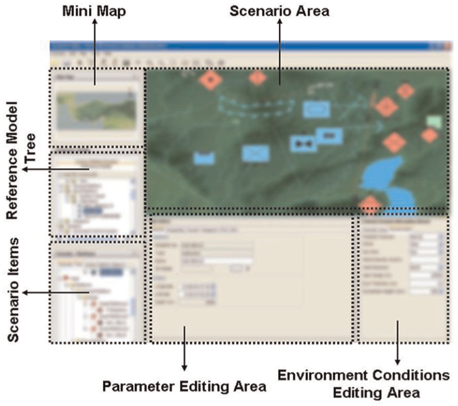
Scenario editor application.
Map definitions are not hard-coded in the Scenario Editor Application; any map in Digital Terrain Elevation Data (DTED) format 30 can easily imported to system. This capability is important especially when using synthetic maps that contain imaginary mountains, islands, etc. for special trainings.
Scenarios prepared with the Scenario Editor can be saved either in an RDBMS- or XML-based 31 scenario files for further modification or execution.
5.6. Scenario player
Scenario Player realizes the requirements listed in Section 4.4.3. During scenario execution, all data exchange between simulation components will be carried out by the framework which is HLA 1516 compliant. Any third-party HLA compliant simulation application (like a spy tool) can easily observe transferred messages according to the FOM of the system.
A screenshot from a scenario execution is showed in Figure 6. Scenario entities are listed at the bottom-left tree. The Application Framework allows integrating scope screens via a 2D display interface module. For example, the scope screen in Figure 6 is a PPI Scope Raw screen that visualizes tracks and clutter for a Surveillance Radar. The Application Framework provides about 15 different predefined scope screens like this for various sensor and communication systems.
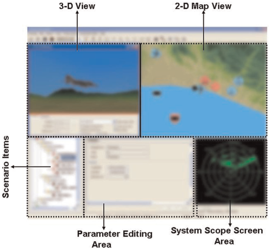
Scenario player.
The Scenario Player is capable of executing scenarios in either single player or distributed multiplayer modes. As an architectural decision, in single player mode both modeling and visualization/control console operations are carried out by a single federate. In multiplayer mode, models are grouped in federates that are running on dedicated servers while each console is a separate federate running on the user’s computer. All communication between the user’s consoles and model federates is carried over HLA 1516 RTI. In single player scenario mode, the Simulation Framework can be configured to loop-back messages between the console and models without using HLA RTI.
Scope and 3D visualization display modules are developed as separate models from the console application, and they have their own SOM definitions. This will ease replacing scope and 3D visualization modules with more complex or third-party visualization tools.
5.7. Common modules
Common functionalities that are used by the simulation environment, model library and support tools are packed in “Common Modules” component. Common modules include the following functionalities to simplify development of new capabilities:
Mathematical calculation and conversion utilities,
Scenario loading, processing and exporting utilities,
Report generation utilities,
Route drawing and processing utilities,
GIS support utilities,
Signal propagation libraries,
Counter Measure Dispenser System (CMDS) components,
Threat evaluation components.
5.8. Support tools
Support tools consist of a set of applications that are developed in the Java Platform to meet the requirements given in Section 4.5. Mapping of the support tools to the FEDEP steps is given in Figure 7.
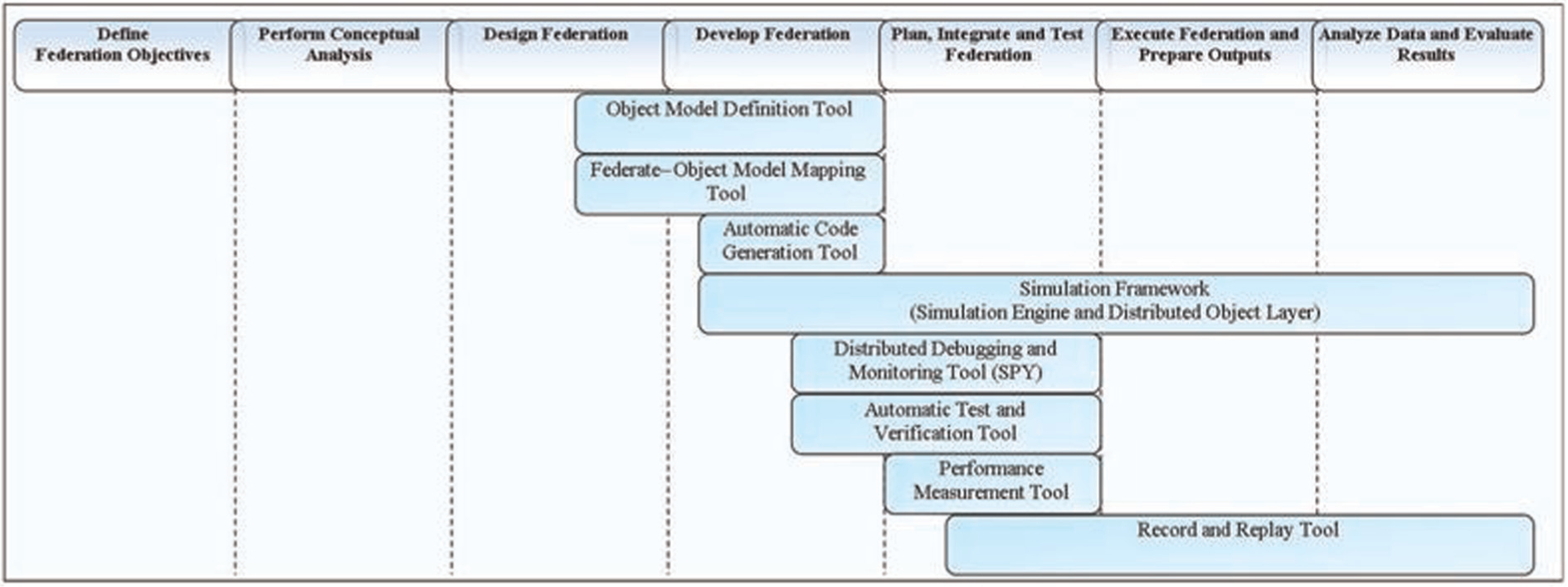
Mapping support tools and simulation framework to FEDEP steps.
The first tool is the Object Model Definition tool that is used in the design and development phases. A similar tool is proposed in Parr. 32 The Object Model Definition tool is designed for developing FOMs in a visual environment. A screenshot from the tool is given in the Figure 8. The FOM elements such as Object Classes, interaction classes, fixed records, enumerations, etc. can be defined and modified by using this tool. In addition to standard properties, this tool also supports defining some additional properties like min/max values that are not available in the HLA Object Model Template (OMT) standard.
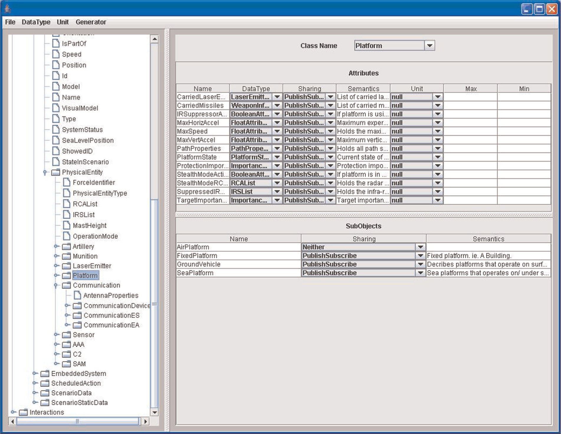
Object model definition tool.
The second tool is the Federate-Object Model Mapping tool which is used in the design and development phases. A screenshot of tool is given in Figure 9. A similar mapping tool is proposed in Parr. 32 The Federate-Object Model Mapping tool allows defining publish/subscribe relations between federates and the FOM elements. These publish/subscribe relations can be used for generating SOM definitions of federates. As mentioned before in Section 5.2, Simulation Models also have SOM definitions just like HLA federates, so this tool can also be used for developing SOM definitions of Simulation Models. The Object Model elements are listed in the left tree and columns are Federates/Simulation Models as shown in Figure 9. Each cell can have value P (Publish), S (Subscribe) or P/S (Publish/Subscribe). P/S relations are defined for each attribute of Object Classes and each interaction class as defined in the HLA standard. The tool is capable of importing /exporting SOMs of Federates/Simulation Models and triggering the Automatic Code Generation tool which will be explained in following part of this section.
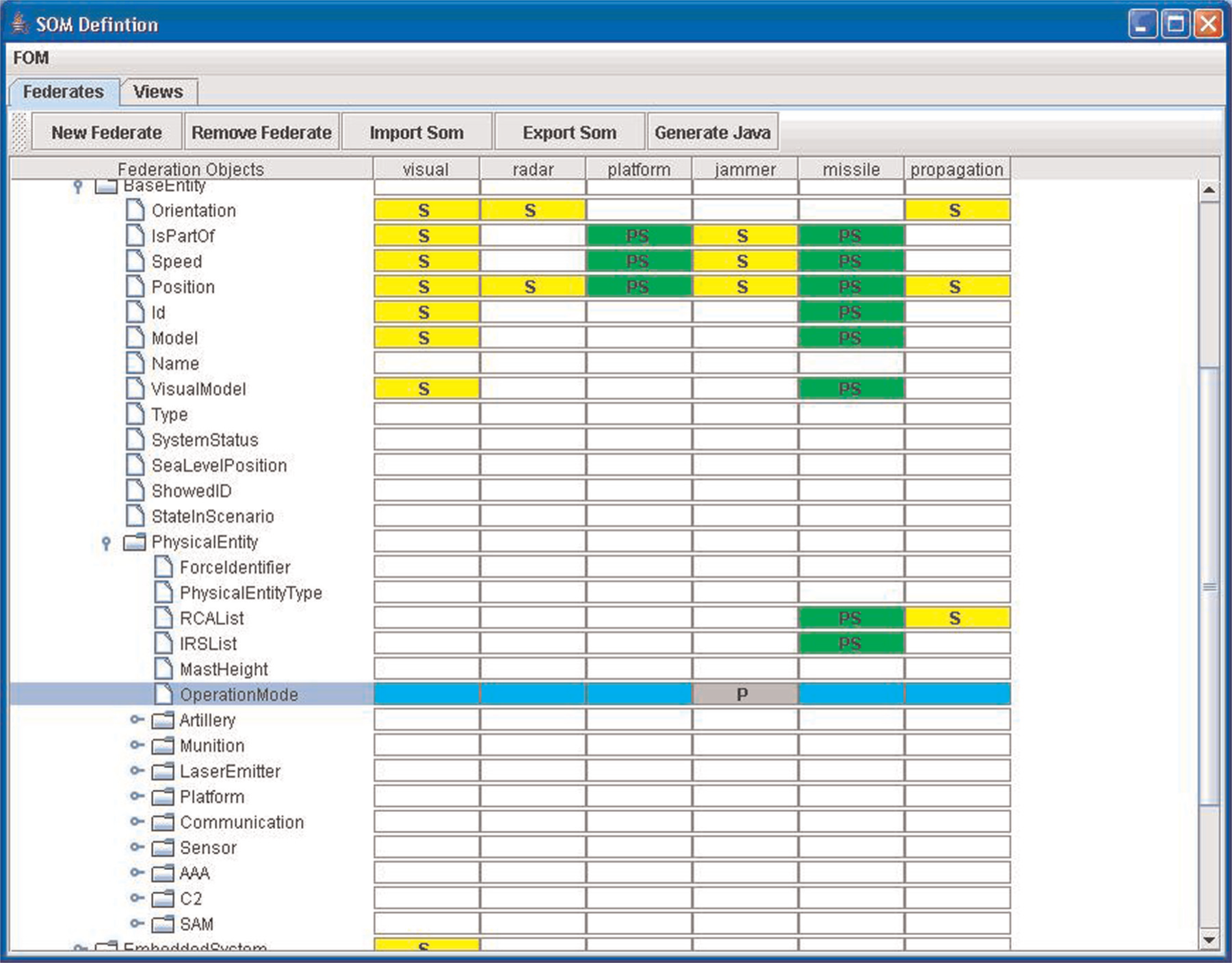
Federate-object model mapping tool.
The third tool is the Automatic Code Generation tool that is used in the development phase. During development of a federation, FOM elements shall be mapped to the target platform (Java, C++, etc.) to enable data exchange between federates. The Automatic Code Generation tool maps FOM elements to the Java Platform by generating Plain Old Java Objects (POJOs) 33 for each data type, object class and interaction classes that the Simulation Framework and the Simulation Models can process. The Object Class Attributes and Interaction Class Parameters are mapped to class fields in the generated code. The generated POJOs also contain encoding/decoding functions for the FOM elements. There are some other tools available in the literature with similar purposes like the code generator for MAK VR-Link tool. 24
As mentioned before about the Reference Models, the reference simulation entities are persisted to the RDBMS via the ORM framework Hibernate. The Hibernate framework uses XML files to define persistent data. Actually, the data model of persistent data can be generated from the FOM definition. The tables in the database will be Object Classes and the columns will be Object Class Attributes. The Automatic Code Generation tool is also capable of generating Hibernate XML mapping files in addition to POJOs.
The fourth tool is the Distributed Debugging and Monitoring tool or simply the “SPY” that is used in the development, integration and test phases. Debugging a distributed and complex application is not an easy process. One of the widely used approaches for debugging distributed applications is monitoring the exchanged data among the participants. There are some tools available in literature for monitoring HLA applications like MAK RTI SPY 34 and Pitch Commander. 35 One of the major requirements defined by the users (simulation development team) for our SPY tool was the capability to pause all federates and to advance time step by step. Model and console federates are designed to be time constrained and time regulating, so we can easily suspend all of them by not advancing time in the SPY application which is also a time regulating federate. A screenshot and a brief description of the functionalities of this tool are given in Figure 10.
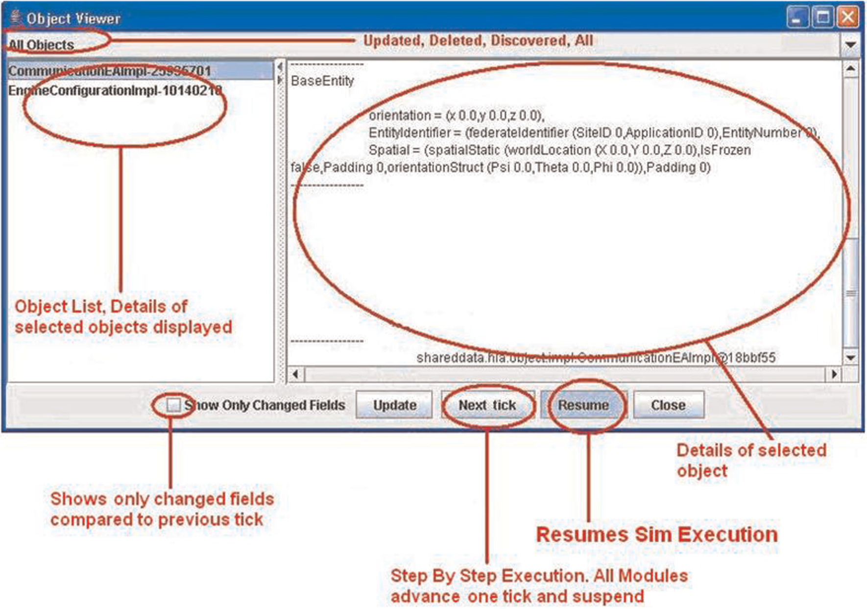
SPY tool.
The second requirement that required us to develop a new SPY application instead of using a COTS tool was the need for injecting HLA messages from the SPY tool. The SPY tool is capable of injecting HLA messages to the system via automatically generated property panels for the FOM elements. The SPY tool uses another in-house developed tool, automatic Java Swing Panel Generator, which can generate Java UI from POJOs for this capability. Figure 11 shows an automatically generated object registration screen.
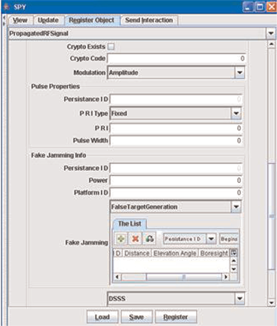
SPY tool, automatic generated message panel.
The fifth tool is the Automatic Test and Verification tool which is used in the development, integration and testing phases. This tool is actually a test framework developed by extending the JUnit framework. 36 The Test and Verification tool enables development of black box tests for simulation models by mocking 23 the behavior of the Simulation Engine. As a JUnit extension, tests can be easily executed in the IDE environments (Figure 12) and deployed to continuous integration systems like Cruise Control. 37 Another advantage of the extending JUnit is gaining the code coverage calculation capability by utilizing tools such as Emma. 38
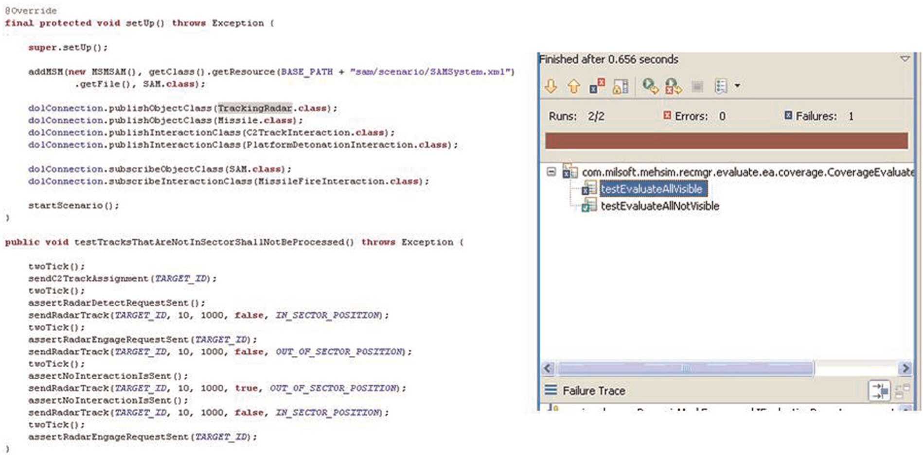
Running tests using JUnit.
The sixth tool is the Performance Measurement tool which is used in the integration and test phases. This tool displays resource consumptions of simulation models as shown in Figure 13.
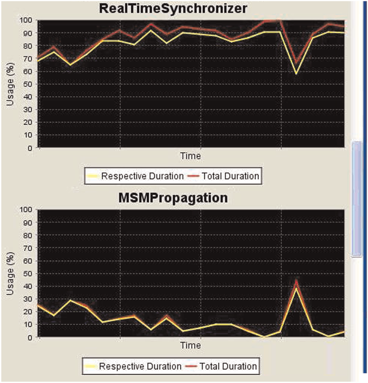
Performance measurement tool.
The last tool is the Record and Replay tool which is used in the integration and testing, federation execution, data analysis and evaluation phases. This tool is capable of recording exchanged data and replaying the recorded data on demand. This tool records scenario execution and publishes recorded data via the HLA during replay. Unlike other support tools, this tool can be a part of the end product. For example, this tool can be utilized by the Scenario Player for AAR and evaluation purposes. There are similar applications for record/replay such as MAK Data Logger 39 and Pitch Recorder. 40 We developed our own Record and Replay tool because we wanted to utilize our own map-based console application for replay and the record application was simple to develop, so it was not worth it to become dependent to a COTS application just for the recording capability.
6. Realization of tactical environment application framework and performance considerations
The Application Framework components are developed and delivered to the end user as part of the JETSIM project,41,42 so performance of the framework is tested and proved in an industrial context.
We encountered some performance problems in the early phases of project. The fidelity level of the developed models was high because of the requirements, but it is also required to add thousands of entities to the scenario especially for multiplayer joint exercises. We performed various measurements and performance improvements on the Application Framework components before shipping the end product to the customer. The distributed execution of the scenarios containing approximately 5000 entities that were successfully accomplished after the performance optimizations on a server with a 2.4 GHz Quad Core Processor, 4 GB of RAM and 32 bit Windows Server 2003 were installed. We used Java Profiling 43 capabilities of various tools44,45 for performance measurements and improvements.
To improve performance especially in the large scale scenarios, we added a disabling capability for some resource consuming capabilities such as replay, player evaluation, reporting and scope displays on demand. These capabilities can be enabled or disabled separately for each scenario in the Scenario Editor.
Since frame rate affects the performance and resolution of the scenario execution, it has been defined as a configurable parameter instead of choosing a fixed value for the entire scenario executions. The frame rate can be set to a lower value in lightweight scenarios for higher fidelity/lower performance or a higher value in large scale scenarios for lower fidelity/higher performance. To give a quantitative value, scenario execution is 500 times faster when comparing the current version of the Application Framework with first functional prototype. This means that a large scale scenario that was running in 500:1 rate (advance one second in 500 seconds) when we first developed the prototype is now running in 1:1 rate in the current version after several performance optimization iterations.
As a sample real system integration case study, an experimental integration of JETSIM with a DDS-based Combat Management System (CMS) – GEMKOMSIS 46 was successfully accomplished. 9 Two systems integrated by using the abstraction and extensibility capabilities provided with Tactical Environment Application Framework. A simple bridge application that was both a simulation module (operating over the Simulation Framework) and also a DDS domain participant was developed to exchange data between systems.
7. Conclusion and future work
In this paper, the requirements and the design overview of a tactical environment application framework which can be used in the development of large scale simulation systems are described.
The Application Framework has been used in a large scale EW Simulation System, JETSIM41,42 which was delivered to the Turkish Army in 2008. JETSIM has been effectively used by the Turkish Army EW Officers since deployment. The robustness and the scalability of the framework have been proven by using it as a part of this product.
The Application Framework reduced the risks and development effort of the JETSIM project according to the collected internal software metrics of MilSOFT. While using the Application Framework, it was observed that the Simulation Framework enables effective software development and simplifies the integration to other systems as expected. Developers were able to focus on developing the behavior of the models by ignoring complex distributed simulation concerns such as time management, synchronization, data exchange, etc. Using the Application Framework decreases the SLOC (Source Lines of Code) of the project by providing reusable components and functionalities. The Application Framework also makes it easy to detect and fix bug/performance issues at the development phase by using the provided tools. Automatic tests that are developed by using the custom test framework and deployed to the continuous integration system to run on a daily basis were very useful for regression tests and helped us to assure that no functionality was broken while modifying or adding capabilities. These capabilities reduce the defect density of the product released to test engineers, so it can be said that using the framework also improves test engineering activities in addition to development activities.
Real system interoperability capabilities of the Application Framework were tested by integrating the JETSIM and GEMKOMSIS projects.
Although this Tactical Environment Application Framework satisfies the requirements for specific applications, new projects that have different requirements may need the built-in Simulation Models to be modified. For example, an EO focused simulation project may require a higher fidelity simulation model for EO sensors and a completely new model for Infrared Counter Measure (IRCM) / Directed Infrared Counter Measure (DIRCM) systems. Required modifications can be performed by using the Application Framework and tools provided by it.
The usability of the framework has been tested in a Local Area Network (LAN) environment. Today, especially in the systems that include both real and simulation systems, integration of geographically distributed systems is required. There are three alternatives for adapting the framework into a Wide Area Network (WAN) environment. The first alternative is using a COTS tool like Pitch Booster 47 which increases the performance on WAN, the second alternative is utilizing Web Service technologies as defined in the HLA Evolved 48 standard, and the third alternative is expanding the simulation environment to support TENA architecture which is especially designed and developed for WAN.
Despite the usage of HLA OMT data models to communicate between components, the Application Framework does not support the Synthetic Environment Data Representation and Interchange Specification (SEDRIS) 49 which standardizes sharing synthetic environment data between applications. Although the HLA standard does not force using this specification, it is considered that adding SEDRIS support to the Application Framework will be useful in order to simplify the interoperability of the systems.
The Application Framework provides modeling tools for designing Object Models and mapping Federates/Simulation Models with Object Models in a publish/subscribe manner. One of missing points in the tools is architectural modeling of Federates/Simulation Models. The available architectural modeling paradigms in literature 50 can be adapted to the Architectural Framework as future work.
Another future work item is dynamic load balancing. The Application Framework allows the user to configure load partitioning before simulation execution, but it does not support dynamic load balancing by migrating simulation models during simulation execution.
Footnotes
Acknowledgements
We would like to thank Türkay Gökdoğan from Skype Inc. for her proofreading and valuable comments.
Funding
This research received no specific grant from any funding agency in the public, commercial or not-for-profit sectors.
Conflict of interest statement
None declared.