
Abstract
It is a well-known fact that an armored vehicle will lose its directional stability when firing a large-caliber gun while moving. The instability is caused by the impulse force from firing, acting at the center of a weapons platform that produces a yaw moment at the center of gravity of the armored vehicle. In order to improve the stability, this paper introduces a firing-on-the-move technology for armored vehicles using an active front-wheel steering (AFS) system. The AFS system is proposed to maintain the directional stability of the armored vehicle by providing an electronically controlled correction to the steering mechanism. The steering correction is designed to reject the unwanted yaw motion and bring the vehicle back to its intended direction of travel after firing. The proposed control strategy of the AFS system in this study consists of yaw rate feedback with lateral force rejection control. The AFS system controller is developed on a validated 10-degrees-of-freedom armored vehicle. The results indicate that the developed control strategy can effectively maintain the directional stability, in terms of yaw and lateral motions, of the armored vehicle after firing. The superiority of the proposed AFS system controller is also evaluated by comparing its performance to an AFS system without lateral force rejection control as well as to a conventional armored vehicle without AFS.
Keywords
1. Introduction
From a vehicle dynamics point of view, vehicle yaw motion can be divided into two categories, the desired yaw motion and the unwanted yaw motion. Desired yaw motion occurs when the direction of travel of the vehicle follows the steering input from the driver, for example in a cornering maneuver. In contrast, an unwanted yaw motion occurs when a vehicle begins to move out of its lane without any steering action from the driver. Side wind force, uneven braking or throttle torques in all four wheels as well as non-uniform tire grip in all four tires are the major factors causing the vehicle to yaw unintentionally. Unwanted yaw motion can cause vehicle accidents, as the directional stability of the vehicle decreases abruptly and the driver may lose control of the vehicle. Considering the importance of yaw stability in a vehicle, research on the development of unwanted yaw rejection mechanisms has been conducted in both academic communities and automotive industries.1–3 Various methods and actuators in yaw stability systems have been developed, such as the traction-control system,4,5 anti-lock braking system,6,7 four-wheel steering controls,8–11 electronic stability program12,13 and active front-wheel steering (AFS) system. 14
In an armored vehicle, unwanted yaw motion can be caused by the firing impulse acting on the center of the weapon platform. The firing impulse will generate yaw moment and lateral force at the body center of gravity (CG), causing the armored vehicle to move out of its intended path, as shown in Figure 1. The technology that is used in most armored vehicles requires static condition during firing because it is unable to maintain the vehicle directional stability if firing is executed during moving condition. Unfortunately, firing in static condition during battle reduces agility and potentially makes the armored vehicle an easy target for a counterattack. Therefore, in order to improve the mobility of the armored vehicle, the involvement of yaw stability control that makes the vehicle able to shoot during moving is a necessity. This paper investigates a firing-on-the-move method using an AFS system in order to reject the unwanted yaw motion and lateral motion subject to gun disturbance. The goal of implementing the AFS system is to maintain the handling quality and directional stability of the armored vehicle by retaining the armored vehicle in its direction of travel during firing on the move.
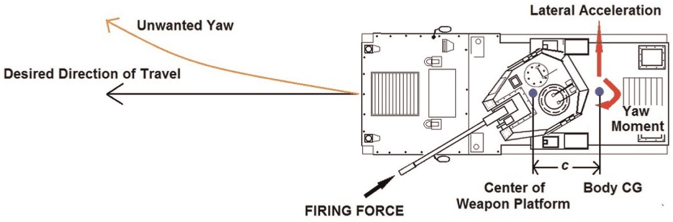
Armored vehicle during firing on the move.
The AFS system maintains the conventional mechanical link between the front wheels and the steering wheel. A planetary gear set, which has two input shafts connected to the steering shaft and a stepper motor, is the one that delivers the variation of the steering ratio in the AFS system. The final steering ratio of the AFS system is basically the superposition between the driver input delivered via a steering shaft and the steering input actuated by the stepper motor. The AFS system is also able to generate a corrective steering response, directly enhancing the vehicle yaw motion. The basic concept of AFS for firing on the move in an armored vehicle is to provide an immediate steering correction to reject the unwanted yaw motion due to firing force. The steering correction, which is electronically controlled using a direct current (DC) motor, is then overlapped with the conventional steering input via the planetary gear set.
In this study, the proposed control strategy of the AFS system for firing on the move consists of an outer loop controller and inner loop controller. The aim of designing the outer loop controller is to reduce the magnitude of unwanted motions due to firing force, namely, the yaw and lateral motions. The inner loop controller is used to provide a steering correction angle using the stepper motor based on the instruction obtained from an outer loop controller. The proposed control strategy is developed using a validated 10-degrees-of-freedom (10-DOF) four-wheeled armored vehicle (4WAV) model. The developed model of the armored vehicles comprises of the 3-DOF 4WAV handling model engaged with a nonlinear tire model—the Calspan tire model and the 7-DOF 4WAV ride model. Validation was performed using a Ferret Scout Car for several driving conditions such as the step steer test, single-lane change test and double-lane change test. The responses obtained from actual handling tests are used as a benchmark for model validation of the 10-DOF armored vehicle model. Then, the proposed control strategy for firing on the move, namely, the yaw rate feedback with lateral force rejection control (LFRC), is developed on this validated model.
This paper is structured as follows: the next section focuses on the mathematical derivation of the 10-DOF 4WAV model. Section 3 shows the development of the proposed control strategy for firing-on-the-move technology with AFS. Section 4 discusses the model validation results of the 10-DOF 4WAV model, followed by the benefits of the proposed AFS system in an armored vehicle in Section 5. Overall conclusions are discussed in Section 6.
2. The 10-degrees-of-freedom armored vehicle model
The 10-DOF model of a 4WAV presented in this study contains the 7-DOF 4WAV ride model and the 3-DOF 4WAV handling model. The 7-DOF 4WAV ride model contains the 3-DOF armored vehicle body motions, which allow the vehicle to pitch, roll and heave. The armored vehicle body is mounted to four unsprung masses at each corner. Each unsprung mass is permitted to heave in the vertical direction. The 3-DOF 4WAV handling model considers the vehicle longitudinal, lateral and yaw motions at the respective axes.
2.1 Ride model for armored vehicle
The 4WAV considered in this study, as illustrated in Figure 2, is based on a category of a movable weapon system that has four wheels and can fire a 75-mm projectile from the gun turret, while the 4WAV ride model is shown in Figure 3. There are several assumptions that need to be considered in developing the 7-DOF 4WAV ride model. The first assumption is that the suspensions system is modeled simply as a combination of spring and damper elements. The second assumption is that the effect of the passive anti-roll bar for vehicle rolling resistance is taken into account in the mass moment of inertia in the x-axis. The tire behavior is also assumed as a linear spring and the vehicle remains grounded at all times so that each tire is constantly touching the road surface during maneuvering. The last assumption is that the position of the suspension system is always in vertical direction.
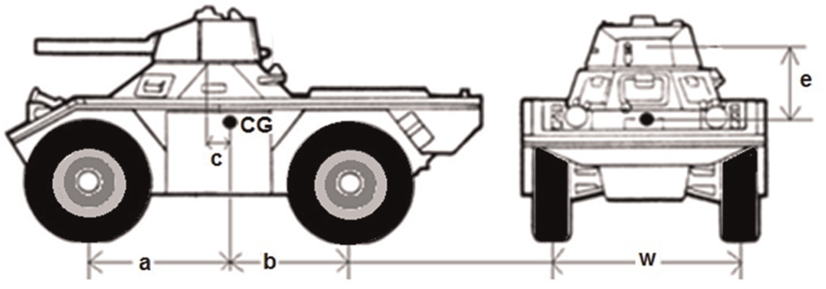
A two-dimensional view of a four-wheeled armored vehicle.
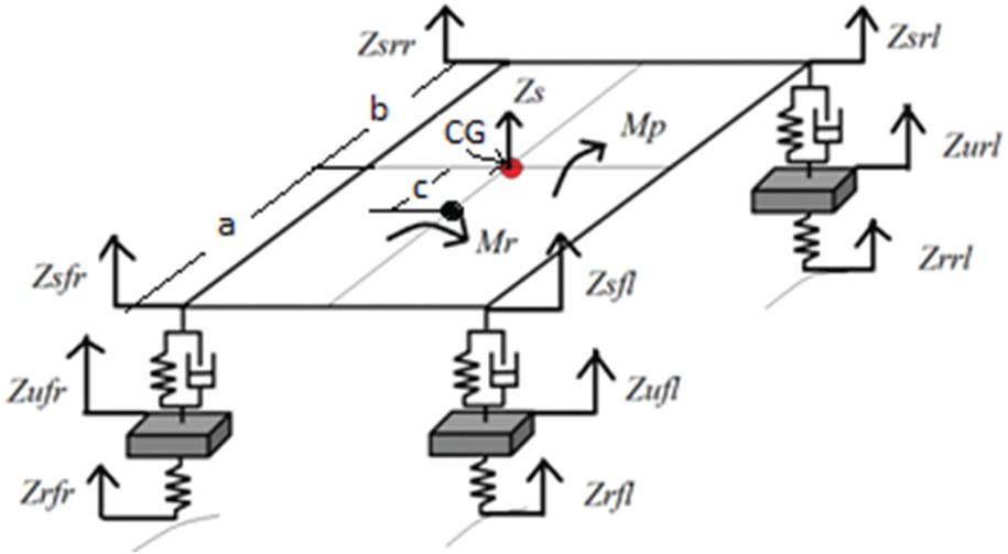
A 7-degrees-of-freedom four-wheeled armored vehicle ride model.
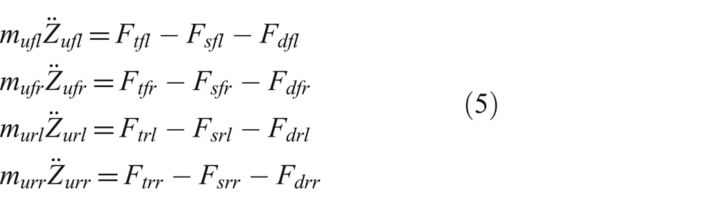
The 4WAV ride model contains the armored vehicle body, four suspension systems and the corresponding tires. The 3-DOF body motions are the armored vehicle heave, pitch and roll. Another 4-DOF is the vertical motions of the four-wheels system at each corner of the armored vehicle. The dynamic behavior of the armored vehicle body in the vertical motion is obtained using Newton’s second law and is presented as follows:

where
ms = weight of sprung mass;
The equation of motion for roll moment is given as
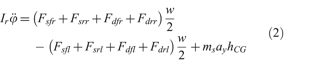
where
Ir = moment inertia of the roll axis;
Similarly, the moment balance equation for pitch motion is given as
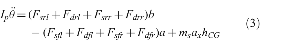
where
Ip = moment inertia of the pitch axis;
a = distance of front tire to the body CG;
b = distance of rear tire to the body CG;
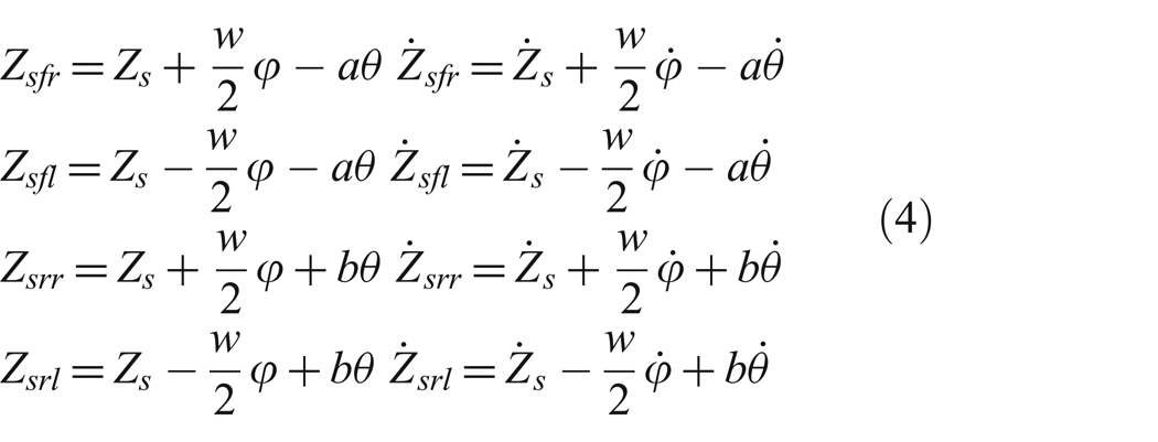
The displacements and velocities of sprung masses for front right, front left, rear right and rear left can be derived in terms of heave, pitch and roll as follows:
where
where
2.2 Handling model for armored vehicle with firing disturbance
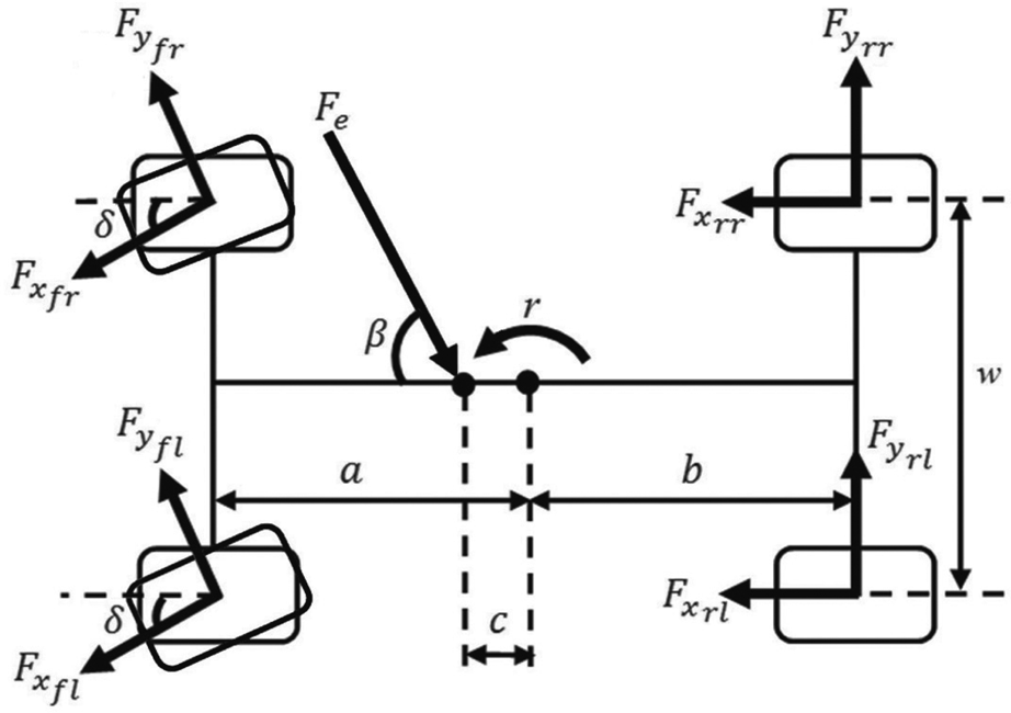
Figure 4 illustrates the 4WAV handling model, which consists of 3-DOF motions: lateral motion, longitudinal motion and yaw motion of an armored vehicle. The firing force (Fe) acting at the center of the weapon platform is located at the distance of c ahead from the location of the CG. The firing force creates unwanted yaw disturbance due to the distance between the center of the weapon platform on the armored vehicle body and the location of the CG. The angle of the firing forces (β) also influences the magnitude of the unwanted yaw moment around the z-axis, lateral acceleration at the y-axis and longitudinal acceleration at the x-axis. There are some assumptions considered in this model. Firstly, it is assumed that the vehicle is traveling without any road disturbances and with a level surface where the gradient is equal to zero. Secondly, the military vehicle is assumed to capable of moving along the longitudinal and lateral directions and to rotate in the z-axis. Thirdly, the steering wheel angle and the wheel steer angle are modeled as a constant ratio, while the steering inertia is neglected in the model. Lastly, the effect of aerodynamic in the horizontal direction is ignored and the armored vehicle is assumed to travel with constant speed, while the effect of longitudinal slip is ignored. The longitudinal acceleration and lateral acceleration in the x- and y-axes are written as ax and ay, respectively, and the yaw acceleration as

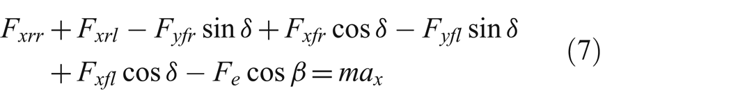
The longitudinal acceleration can be obtained by considering the forces acting at each tire in the x-axis as
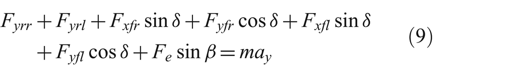
In addition, acceleration in the lateral direction is written as

Similarly, the lateral acceleration is obtained by considering the forces acting at each tire in the y-axis:
The yaw angular acceleration acting on the armored vehicle handling model is also based on the effects of tire forces, namely, the lateral force and longitudinal force. It can be derived as
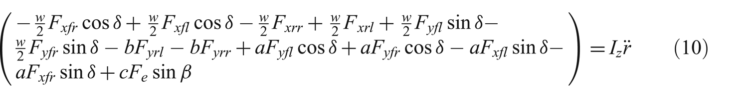
where
δ = wheel steer angle;
m = armored vehicle mass.
Armored vehicle handling model with firing disturbance.
After obtaining the three main vehicle dynamic parameters of the military vehicle (i.e., longitudinal acceleration, lateral acceleration and yaw angular acceleration), the parameters are then used to estimate the slip angle of front tire (
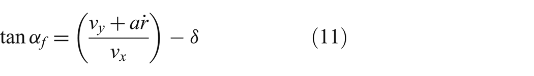
and
where
2.3 Firing force model
The firing force acting at the gun platform can be explained using the relationship of impulse and momentum. Impulse can be used as a basic concept to estimate the linear momentum of firing force obtained from the projectile based on the mass and velocity of the projectile. 15 The correlation between the impulse and momentum of the projectile leaving a muzzle can be written as
where Mp is the mass of the projectile, vo is the initial speed of the projectile, vf is the speed of the projectile leaving the muzzle and Δt is the time required by the projectile to obtain its maximum speed at the muzzle. To evaluate the performance of the proposed control strategy, the firing force is defined as a step function produced by a 75-mm caliber gun, as shown in Figure 5. In this study, the firing angles are set in 30°, 60° and 90° to the right-hand side of the armored vehicle.
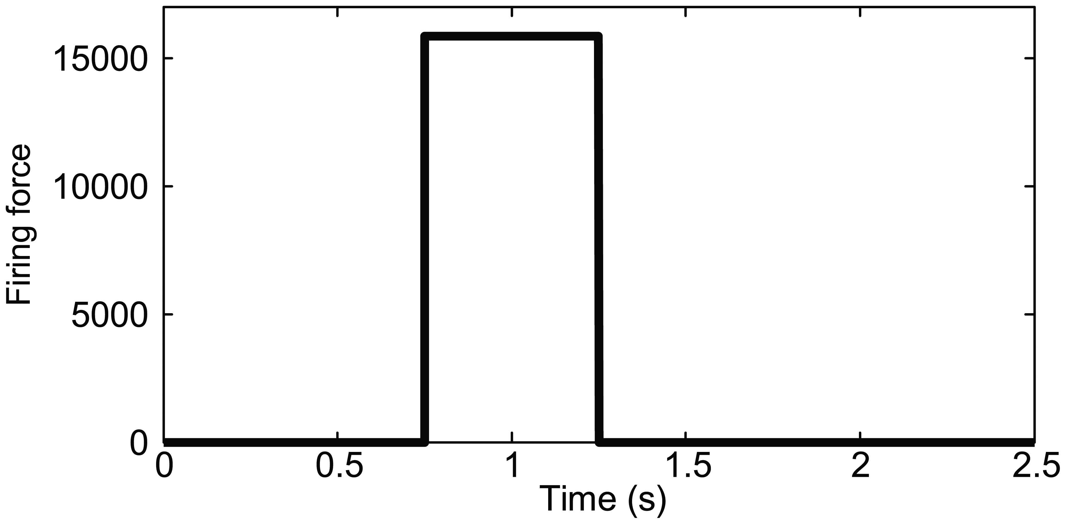
Firing force produced by a 75-mm caliber gun.
3. Basic configuration and proposed control strategy of active front-wheel steering for a four-wheeled armored vehicle
The AFS for a 4WAV is built by retaining the conventional mechanical parts, such as the steering wheel, the steering shaft, the recirculating ball gearbox, the pitman arm and the steering arms. In AFS, there are two angles that need to be evaluated: the steering wheel input given by the driver and steering correction angle produced by the controller and actuated by the AFS actuator, as illustrated in Figure 6. There is an additional gearbox between the steering shaft and AFS actuator to superimpose the steering wheel angle obtained from the driver and angle of steering correction from the AFS actuator. The combinations of both angles provide a correction angle for wheel steer angle through the pitman arm.
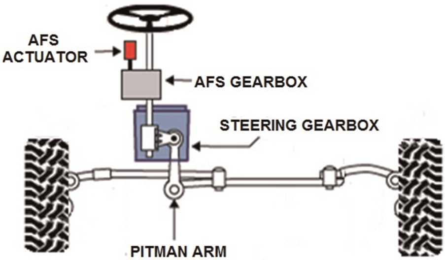
Configuration of active front steering using pitman steering.
The control strategy is developed using a validated 10-DOF 4WAV model by assuming that the armored vehicle travels in a straight direction without any steering input given by the driver. The control strategy of AFS consists of an inner loop controller and an outer loop controller, as shown in Figure 7. The outer loop controller is used for rejecting the unwanted yaw motion and preventing lateral movement of the armored vehicle using a LFRC. In developing the outer loop controller, the desired yaw rate (yd) is compared to the actual yaw rate feedback (ya) obtained from the validated armored vehicle model. A proportional-integral-derivative (PID) controller is used in the yaw rate feedback controller to process the yaw rate error and producing the desired lateral force (Fyd) to be used for the next controller loop, namely, the LFRC loop. The desired lateral force is defined as
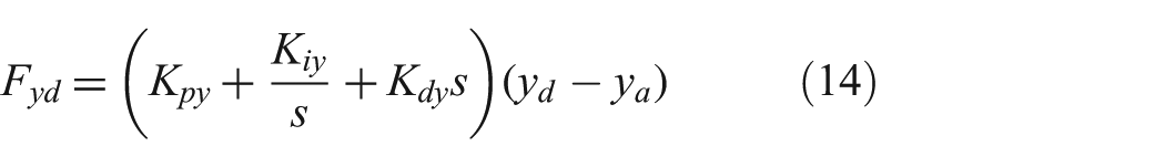
where
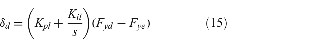
where Kpl and
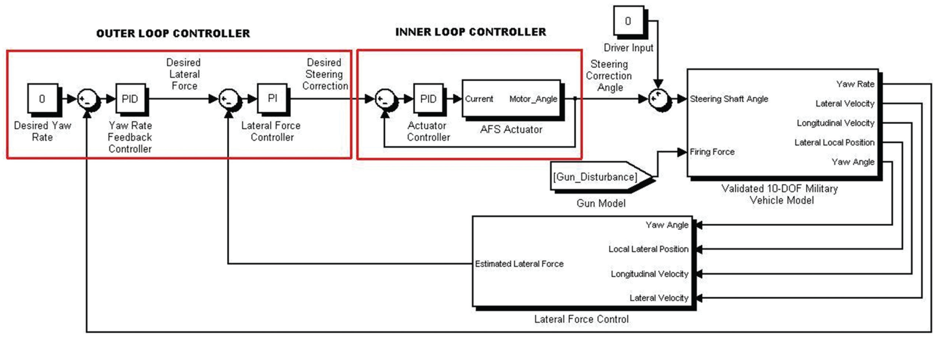
Control strategy of the active front-wheel steering for a four-wheeled armored vehicle.
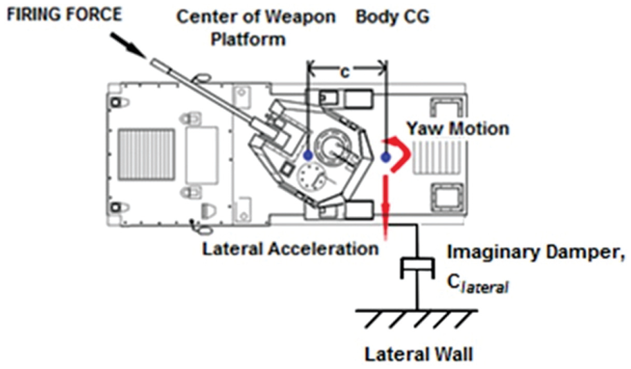
Armored vehicle with imaginary lateral wall and imaginary damper.
The estimated lateral force (Fye) is defined as

where
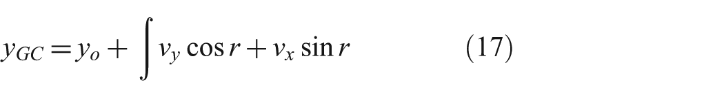
where
yo = local lateral displacement;
r = armored vehicle yaw angle;
vx = armored vehicle longitudinal velocity;
vy = armored vehicle lateral velocity.
The output produced by the outer loop controller, that is, the desired steering correction angle (δd), will be used as the reference for inner loop controller. The purpose of the inner loop controller is to monitor the AFS actuator that uses a stepper motor as the torque-generator device. The stepper motor should be able to track the desired steering correction angle of δd and provide the ideal steering correction angle (δ) for the steering shaft. In this study, modeling of the AFS actuator using the stepper motor in providing the ideal steering correction angle is directly related to the stepper motor model developed by Morar. 16
4. Validation of the 10-degrees-of-freedom four-wheeled armored vehicle model
In order to validate the 10-DOF 4WAV model, actual handling tests are conducted using an actual armored vehicle. Several transducers are installed in the armored vehicle to sense the vehicle’s behavior (i.e., lateral acceleration, roll angle, yaw rate and steering input) from the driver input. Validation of the developed armored vehicle model can be defined as an assessment of the developed model’s behaviors with the actual armored vehicle’s behaviors. The validation of the armored vehicle model is done by comparing the behaviors obtained from the simulation model with actual responses obtained from the experimental armored vehicle using the similar handling test. The experimental results are also used to evaluate whether the vehicle parameters for the model development are acceptable.
4.1 Instrumented experimental military vehicle
The ArduIMU V3 and direct interface with microcontroller, namely, the USB-to-UART converter, are mounted into the actual armored vehicle to analyze the armored vehicle’s behavior (i.e., body yaw rate, body roll angle and body lateral acceleration). The ArduIMU V3 consists of two types of sensors: the tri-axial accelerometer to sense linear accelerations at the CG and the tri-axial gyroscope for the angular rate. In order to obtain the steering wheel angle, a transducer, namely, the rotary encoder, is connected to the MCC DAQ as a real-time data collector. The installation of the ArduIMUV3, the USB-to-UART converter, the MCC DAQ and the rotary encoder into the armored vehicle are illustrated in Figure 9.
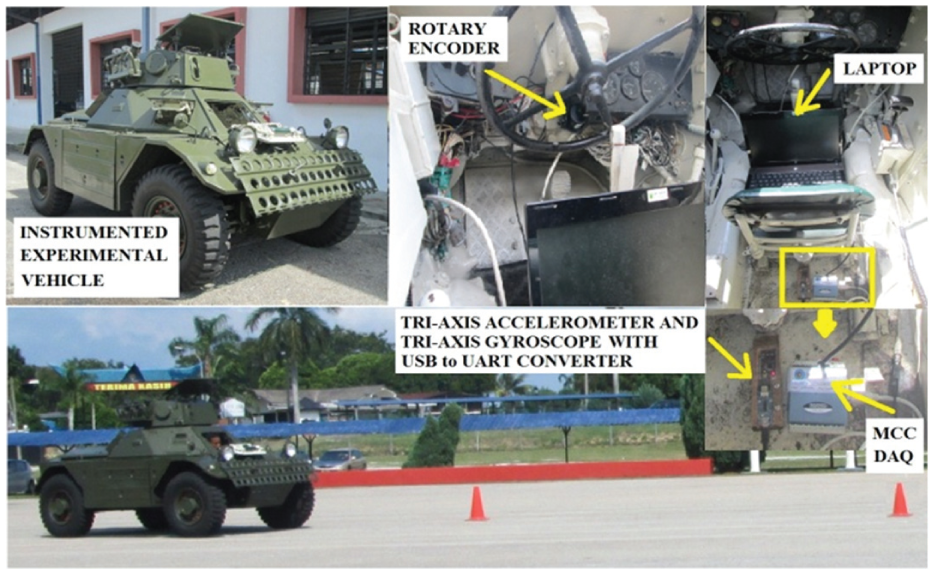
Four-wheeled armored vehicle equipped with sensors.
4.2 Model validation procedures
The performance of the armored vehicle model can be validated by benchmarking with the experimental data of an armored vehicle maneuvering in the step steer test, single-lane change test and double-lane change test. The step steer test is used to investigate the transient handling behavior of the armored vehicle. In this study, the transient response of the armored vehicle is investigated through the step steer test with steering input of 90° clockwise at 20 km/h. On the other hand, the single-lane change and double-lane change tests are conducted to evaluate the road holding capability of the armored vehicle in avoiding an obstacle. In this study, the armored vehicle speeds are set at 30 km/h for the single-lane change test and 40 km/h for the double-lane change test.
4.3 Results of model validation
All the actual results obtained from the experimental tests are filtered using a low-pass Butterworth filter. The steering input from the driver is recorded by a rotary encoder and will be used as the steering input in the simulation of the armored vehicle model in the simulation. The armored vehicle specifications are measured from the actual specification of the armored vehicle; however, several parameters are assumed and obtained from the previous works. The results of the armored vehicle model validation for steep steer, single-lane change and double-lane change tests are demonstrated in Figures 10–12.
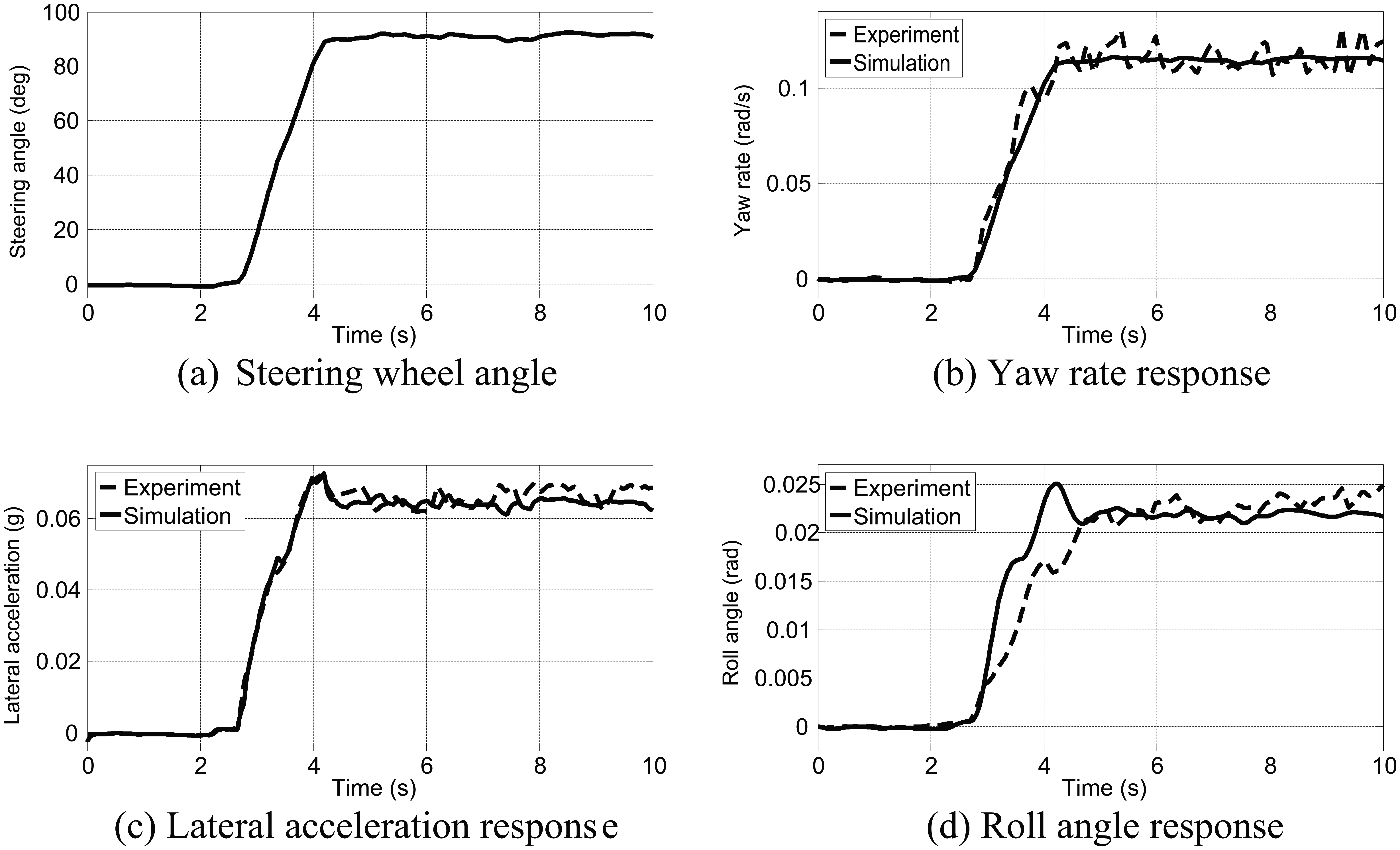
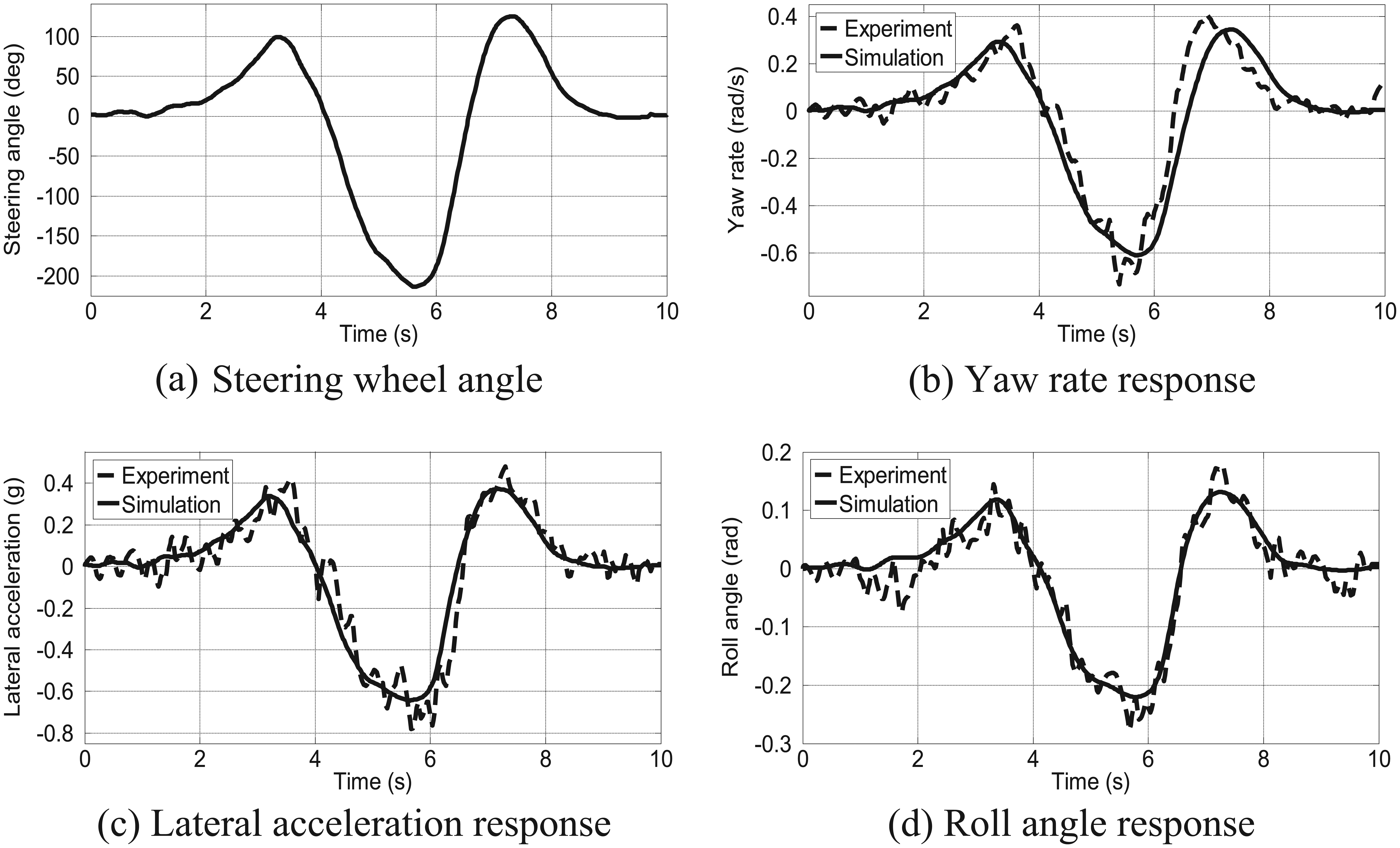
Validation results for 20 km/h step steer test.
Validation results for 30 km/h single-lane change test.
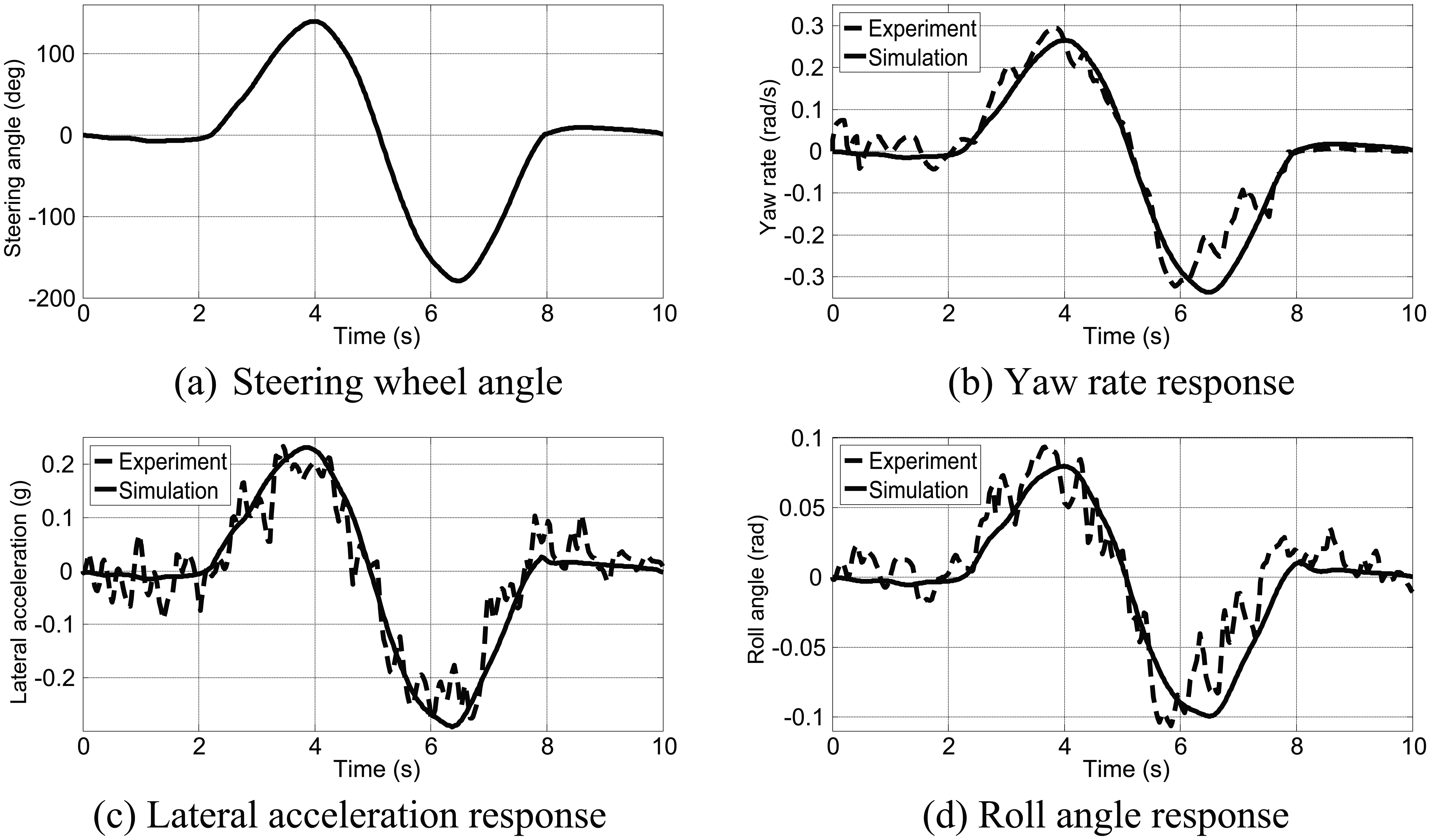
Validation results for 40km/h double-lane change test.
Figure 10(a) illustrates steering input from the driver during the step steer test, which is set as the steering input for the developed armored vehicle model. Figures 10(b)–(d) illustrate the validation results of the armored vehicle: yaw rate response, lateral acceleration response and roll angle response, respectively. From the validation result for the step steer handling test, it is clear that the behaviors and magnitudes between simulation results and actual data obtained from experimental work show good similarity with minor errors, particularly for the roll angle response. The minor error of the roll angle is due to the assumption in development of the armored vehicle model where the stabilizer bar was not considered. In a real-world application, the purpose of the stabilizer bar is used to reduce the roll motion response of the armored vehicle body. For yaw rate and lateral acceleration responses, better similarity in the responses are shown starting from the initial phase until the steering input is introduced to the armored vehicle. It also can be seen that the data of the experimental results contains some chattering caused by the effect of the actual road profile and the engine vibrations. Noise and data chattering from experimental works can be removed using a correct filtering technique.
To ensure that the developed model is valid in representing the actual 4WAV, the model validation is also performed for the 30 km/h single-lane change test and 40 km/h double-lane change test. The results of the validation for the single-lane change and double-lane change tests show that the results from actual data and the simulation results have good correlation, as can be seen in Figures 11 and 12, respectively. Figures 11(a) and 12(a) show the actual steering input delivered by the driver in single-lane change and double-lane change tests. The validation results for the single- and double-lane change tests (i.e., the lateral acceleration, yaw rate and roll angle responses) show that the results obtained from simulation are able to track the actual maneuver results with similar trends and magnitudes, as demonstrated in Figures 11(b)–(d) as well as 12(b)–(d), respectively. The small deviations in the validation results might be caused by the problem of the driver in maintaining a constant speed for both actual handling tests. It also can be due to the assumption in simulation where the steering inertia is neglected. For the overall validation results, it is clear that the behaviors obtained from the simulation works and the experimental works for the three tests have similar responses with acceptable error. The validated armored vehicle model is then used to assess the performance of the proposed control strategy of the AFS system in Section 5.
5. Performance evaluation of the proposed control strategy for active front-wheel steering
The investigation on the performance of the proposed control strategy for AFS with an additional LFRC loop is presented in this section. Responses obtained from the passive armored vehicle are set as the basic benchmark for performance evaluation of the proposed control strategy. To evaluate the benefit of additional LFRC, comparison between the behaviors of the proposed control strategy and AFS without a LFRC loop is made. This section starts by explaining the selection of the parameters of the armored vehicle and proposed control strategy parameter used in the simulation work, as well as demonstrating the AFS performance in various firing angles at a constant speed of 40 km/h. The proposed control strategy for AFS is tested for its performance in enhancing both lateral motion and yaw motion of the armored vehicle after firing in terms of several performance characteristics: lateral acceleration, lateral position, yaw rate and yaw angle.
5.1 Parameters of the developed armored vehicle model
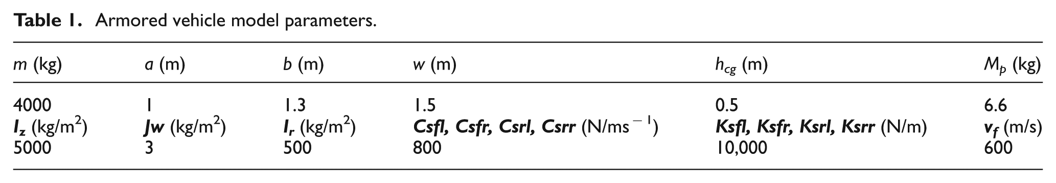
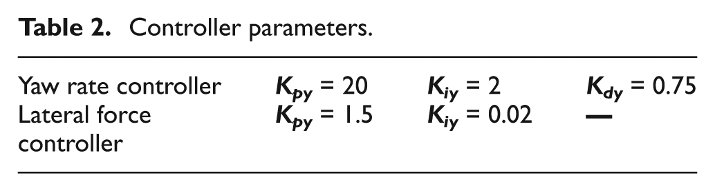
The performance of the proposed control strategy is measured for the duration of 2.5 seconds. The parameters of the vehicle controller (i.e., yaw rate feedback and lateral force controllers) are tuned using the Ziegler–Nichols method. The armored vehicle parameters (i.e., the 10-DOF 4WAV model parameters, vehicle yaw rate controller and vehicle lateral force controller) are shown in Tables 1 and 2, respectively.
Armored vehicle model parameters.
Controller parameters.
5.2 Performance of the AFS with firing angles of 30°, 60° and 90°
Figure 13 shows the simulation results of the steering correction angle actuated by the stepper motor for firing angles of 30°, 60° and 90° at 40 km/h. The magnitude of the steering correction angle must be complied with to ensure that the proposed control strategy can maintain the desired direction of travel after firing.
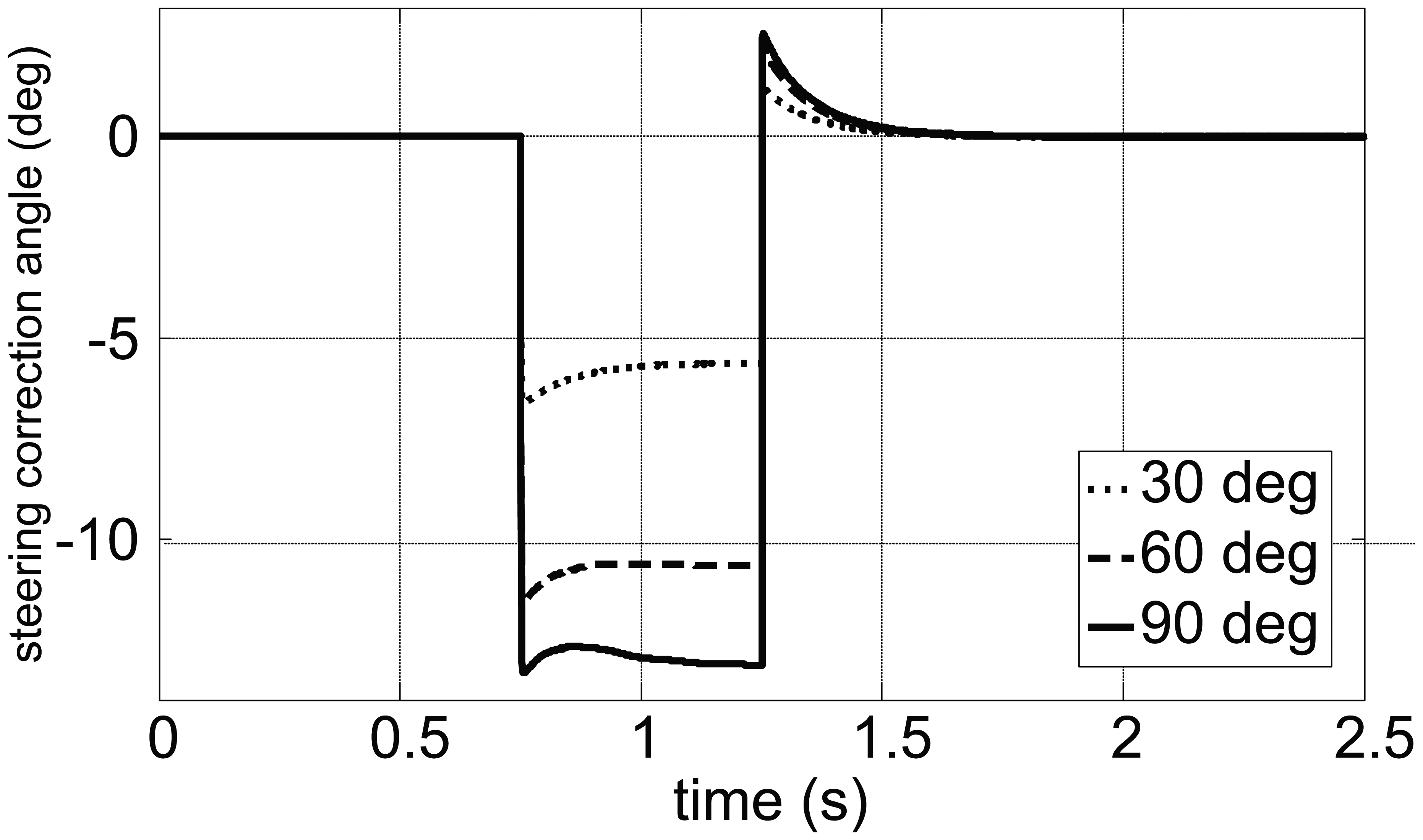
Steering correction angles for 30°, 60° and 90°.
The simulation results of the lateral motions (i.e., lateral acceleration and lateral position at the CG of the armored vehicle at the speed of 40 km/h for firing angles of 30°, 60° and 90°) are demonstrated in Figures 14(a)–(f), respectively. It is observed that the proposed control strategy of both AFS with LFRC and AFS without LFRC can improve the performance as compared to the passive armored vehicle. In terms of the lateral acceleration responses of these three firing angles, AFS with LFRC shows a slight improvement in reducing the magnitude of lateral acceleration against the AFS without LFRC. In terms of lateral position responses, it can be seen that the lateral position for both AFS without LFRC and the passive armored vehicle are increasing relative to time after firing. In terms of lateral displacement, it is very clear that the benefit of AFS with additional LFRC can effectively improve the armored vehicle performance in terms of maintaining the military vehicle to travel in the straight direction after firing compared to its counterparts, namely, AFS without LFRC and a passive armored vehicle. Improvement in the lateral position response after firing can increase the mobility performance of the armored vehicle. It can be said that the proposed AFS with the control strategy has the potential to be used for firing-on-the-move technology for armored vehicles.
Lateral motion responses of active front-wheel steering (AFS) for various firing angles.
The performances of the proposed control strategy in eliminating the unwanted yaw motions at 40 km/h and firing angles of 30°, 60° and 90° are indicated in Figures 15(a)–(f), respectively. The yaw rate response of AFS with LFRC is compared to AFS without LFRC and an armored vehicle with a passive steering system. For the yaw rate response, it is perceived that the proposed control strategy of AFS with LFRC is very effective in reducing the magnitude of yaw rate error compared to its counterparts. The proposed control strategy managed to reject the magnitude of yaw rate error almost 80% over the armored vehicle equipped with a passive steering system. The major improvement of yaw rate response has the potential to increase the target accuracy as well as decrease the percentage of human faults during firing on the move.
Yaw motion responses of active front-wheel steering (AFS) for various firing angles.
For yaw angle response, the performance of AFS with LFRC shows an excellent response compared to AFS without LFRC and the armored vehicle equipped with a passive steering system by canceling out the yaw angle error, which has the capability to return back to its desired direction of travel after firing. From the results obtained, it also can be seen that the maximum magnitude of yaw angle error for AFS with LFRC is very small and can be neglected. The capability of AFS with LFRC to retain the directional stability after firing with various firing angles is also observed. The ability of the proposed control strategy in cancelling out the magnitude of the yaw angle can enhance the handling quality of the armored vehicle in the presence of firing disturbances while moving. Since the yaw rate and yaw angle responses of AFS with LFRC show better improvement using the proposed control strategy, the possibility of the developed control strategy improving the target accuracy during firing on the move also can be achieved.
Figures 16 (a)–(d) show the detailed responses of the proposed control strategy, namely, AFS with LFRC, in enhancing the dynamic qualities of an armored vehicle for firing at angles of 30°, 60° and 90° at 40 km/h. The comparison of armored vehicle responses is used to demonstrate the usefulness of the developed control strategy to reduce unwanted yaw motion and unwanted lateral motion in any firing angles. It is very clear that the proposed control strategy can improve the armored vehicle dynamic qualities during firing with various firing angles. The maximum unwanted yaw moment acting on the weapon platform occurs at the 90° firing angle.
Active front-wheel steering with lateral force rejection control responses.
6. Conclusion
A 10-DOF 4WAV model has been developed using MATLAB-Simulink and validated experimentally through the step steer, single-lane change and double-lane change handling tests. The validation results of yaw rate response, lateral acceleration response and roll angle response show that the responses of the developed armored vehicle model are able to track the behaviors of an actual armored vehicle measured by several sensors. From the model validation results, it can be said that the developed armored vehicle model can be used to simulate armored vehicle responses in any maneuvering tests. In terms of armored vehicle responses of the proposed control strategy, it can be concluded that the performance of the AFS with LFRC is able to reduce and eliminate the unwanted yaw and lateral motions in all the selected firing angles compared with the armored vehicle equipped with the passive steering system. The need of LFRC to the yaw rate feedback is strongly proven compared to AFS without LFRC. Overall, it can be said that AFS with LFRC of the armored vehicle application in firing-on-the-move technology significantly improves the stability level of the armored vehicle by lowering the magnitudes of lateral acceleration, lateral displacement and yaw rate, as well as eliminating the yaw angle after firing. Enhancement of armored vehicle stability will reduce the risk of the driver losing control caused by firing action, as well as increase the firing accuracy.
Footnotes
Acknowledgements
The authors would like to thank the Malaysian Ministry of Education, the Institut Kejuruteraan Tentera Darat (IJED) and the Malaysia-Japan International Institute of Technology (MJIIT) for the use of their research facilities for this research.
Declaration of conflicting interest
The authors declare that there is no conflict of interest.
Funding
This work was supported by the Malaysian Ministry of Education through LRGS (LRGS/B-U/2013/UPNM/ DEFENCE & SECURITY-P1), RAGS (RAGS/2012/ UPNM/TK01/4), the Institut Kejuruteraan Tentera Darat (IJED) and the Malaysia-Japan International Institute of Technology (MJIIT).