
Abstract
This paper aims at assessing a custom numerical procedure built to predict the level of stress in the structural components and equipment in proximity of a cannon-like weapon system when firing. In such a blast scenario, the structures adjacent to a gun may undergo sudden and unwanted damages, since they are commonly subjected to the blast load due to the impingement and propagation of the shock waves expanding from the weapon muzzle. The proposed procedure pertains the coupled use of an in-house developed tool (GUNWave3D) based on the power-law scaling technique and a general-purpose commercial fast dynamic solver to compute the structural response of the loaded components. The in-house tool, in particular, allows one to rapidly calculate the blast parameters over the surfaces of the items of interest in the function of the weapon characteristics and launch conditions, also accounting for the asymmetric shape characterizing the gun blast wave. Taking as reference the numerical free field peak overpressure profiles of a 30 mm gun, whose blast quantities were already validated in a previously published work, the final stage of the assessment was accomplished. Such an estimation consists of the comparison between the structural stresses calculated using the blast loads predicted through the in-house tool and those computed adopting the free spherical air blast of the tri-nitro-toluene model. This operation has the objective to quantify the discrepancy between the computational results of two Lagrangian techniques that can be alternatively adopted in industrial gun blast design procedures and methodologies.
Keywords
1. Introduction
Gun firing typically comprises several physical phenomena, such as blast, pressure, and acoustic waves, as well as muzzle flash and smoke. Specifically, the primal blast wave, due to the exit of the main propellant gas plumes, has a strength that depends upon several parameters, including the caliber of the gun and the exit flow properties that, in turn, depend upon the design of the charge and interior ballistic performance during in-bore combustion.
As the overpressure levels associated with the main gun blast can be such to cause undesirable harmful effects on structures, sensitive equipment, and crew members, during the 20th century many techniques were developed to reliably support blast designers in predicting the gun blast field and load so as to quantify the related risk and, accordingly, to set up adequate countermeasures, such as the modification of weapon emplacement, the selection of blast-resistant protection, and the determination of limiting values for the weapon firing arcs. Each approach comes with advantages and drawbacks and is strictly dependent upon the availability of gun experimental data, consisting of the free field peak iso-overpressure profiles that, as can be reasonably understood, are confidential in most cases.
If the blast designer is provided with these data, several methods with a different level of detail in achievable outputs may be adopted. Likely, the simplest method is to directly draw the structures of interest relative to the muzzle bore at firing on the experimental maps in order to approximately evaluate the peak incident overpressure. Then, in view of evaluating the related approximate reflected value, blast handbooks reporting the explosive blast loads from conventional explosive on structures1–3 or polynomial formulations 4 may be employed, taking into account the blast parameters concerning the spherical air burst of tri-nitro-toluene (TNT).
A more complex method pertains to the use of three-dimensional computer-aided design (CAD) tools that, once the iso-value experimental surfaces are created by performing a geometrical revolution of the two-dimensional experimental profiles and moved integrally with the gun barrel, allow designers to quickly determine the approximate value of the peak incident overpressure in the function of the firing position. From a different design perspective, blast handbooks or polynomial formulations data can be exploited to suitably calibrate the TNT equivalent mass according to a specific design assumption, such as the best fitting of an iso-overpressure curve or of a specific area of interest of the experimental data, in view of approximating the gun blast wave and running detailed blast simulations through the so-called hydrocodes (hydrodynamic codes), one of the most powerful and effective design solutions available to date. Examples of commercial and extensively validated hydrocodes are AUTODYN, 5 LS-DYNA, 6 and ALE3D. 7 In function of their range of applicability, such numerical means implement different models, including Lagrangian techniques8–10 coupled with empirical models3,11 as well as multi-material arbitrary Lagrangian–Eulerian (MM-ALE)12,13 and smooth particle hydrodynamics (SPH)14–16 models.
On the other hand, a more limited set of methods can effectively support the blast designer regardless of the availability of gun experimental data. Apart from the cases of military standards proposing analytical closed formulations and models mainly based on geometrical inputs, such as the barrel elevation and distance between the bore and the deck, there are firstly advanced methods envisaging the utilization of computational fluid dynamics (CFD) techniques and tools.17–22 Such an approach enables the simulation of a large variety of blast scenarios ranging from internal to external ballistics of the projectile.
Another class of methods of great interest, considering the targets of the present paper, deals with the scaling law-based models. Since their inception,23,24 this well established and extensively employed procedure supplies the main blast parameters in a very fast manner making use of experimental data registered during massive gun firing campaigns in order to properly calibrate and enrich the accuracy in prediction.25–32 In this context, the contribution given by the author consists of the development of a tool, 3 called GUNWave3D and briefly described in Section 4, to determine the blast load over solid reflecting surfaces of three-dimensional models near the cannon muzzle by exploiting the theoretical framework of relevant works previously published in this context.34–36
Related to this latter methodological approach, it is worth mentioning that, although the power-law scaling laws models are able to simulate a large range of guns, the availability of experimental data allows the analyst to enable, if needed, the calibration of the input parameters value of the tool in view of better approximating the gun blast incident quantities in a specific area of interest.
2. Overview of the main contents of the paper
After providing a brief review of the fundamentals of gun blasts in Section 3, a summary description of the in-house developed tool used in the proposed coupled approach is provided in Section 4.
Then, Section 5 reports the logic, implementation, and key characteristics of the coupled approach as well as the procedure followed to verify the proper application of the blast loads calculated by means of the in-house tool.
The results of the assessment are described in more depth in Section 6. In particular, the calibration of the TNT charge to enable the numerical analysis of the employed hydrocode is detailed together with the main settings of the computational case. Finally, the computing of the stress levels gained by means of the two Lagrangian approaches are shown, compared, and judged in Section 7.
3. Gun blast fundamentals
A simplified pressure–time disturbance registered for the free field blast at any given point surrounding the muzzle bore is reported in Figure 1. When the primal (main) shock front due to the release of propellant gases arrives at time
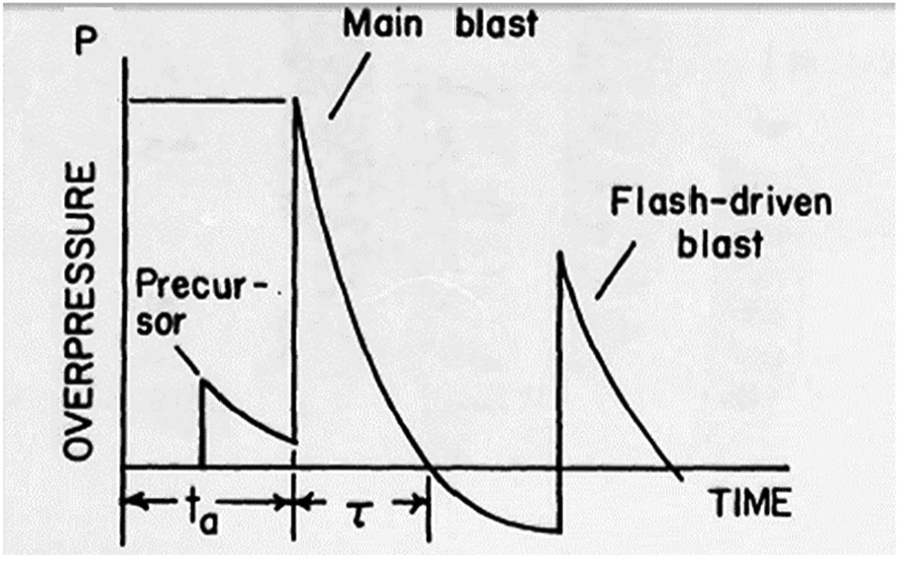
Schematic of the overpressure pulse of the gun blast wave. 37
The blast wave free field is characterized by a remarkable directionality that induces a spatial asymmetry in the overpressure distribution (see Figure 2(a)), whose shape is typically a function of the cannon, propellant, and projectile characteristics.
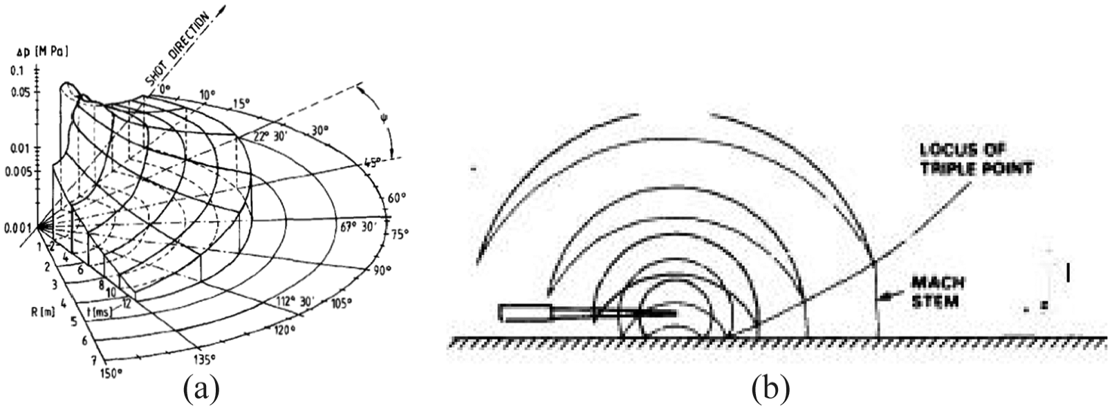
When the shock front of the blast wave reaches the ground surface, a reflection characterized by a substantial reinforcement of the pressure level occurs. Moreover, the interaction between the incident and reflected pressure waves results in a formation of the so-called Mach stem, which propagates normal to the surface and terminates in a triple point, at some distance above the ground, identifying the conjunction of the Mach stem, the reflected wave, and the incident wave (see Figure 2(b)).
4. Gunwave3D model description
The GUNWave3D tool
33
provides the distribution of peak incident overpressure
The calculation of
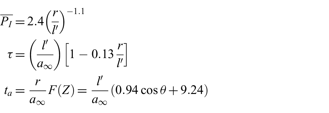
where
The field value of
Following the just-described theoretical framework, taking as input the discretized surface of the model to study in STereoLithography (STL) format, both peak and transient pressure distributions are supplied by generating output data in vtk American Standard Code for Information Interchange (ASCII) format that can be displayed by means of the multi-platform data analysis and visualization application Paraview. 39
5. Coupled approach description
5.1. Logic, implementation, and key characteristics
The coupled approach basically concerns the transfer of the blast data calculated through GUNWave3D to the general-purpose commercial multi-physics simulation software package LS-DYNA to compute the transient structural response of the system to be studied, adopting the Lagrangian approach.
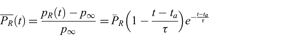
Specifically, the time of arrival
that acts during the duration of the positive phase. Such an operation is automatically accomplished by means a script file written in Python programming language, 40 assuming that the geometry of both cases has the same position.
Given the way the numerical process has been conceived and designed, the meshes of the two numerical cases do not mandatorily need to overlap and, moreover, they can have a different resolution and element typology.
The main advantages of the coupled approach are the intrinsically stable and fast computing of gun blast data that takes into account the asymmetry of the blast wave. Besides, such a procedure can be enabled even if the cannon experimental data are not available. In contrast, the main drawbacks are the fact that the pressure load is not available at the surface not facing the muzzle bore and refers just to the positive phase, and that the calculation is not suitable to detail specific blast related phenomena, such as the blast load reinforcement due to the impact of different shock fronts created by multi-reflecting surfaces (e.g., containment effects).
5.2. Blast load application verification
In order to validate whether the coupling of the proposed method is coherent, the correctness of the application in the hydrocode case of the blast load calculated through the in-house tool, already tackled by Costa, 41 was verified. To this end, the transient gun blast loads set up using the parameters gained with the in-house tool validation 33 were employed. Such data specifically refer to experimental measurements available in the literature and regard a firing configuration of a 30-mm XM230 Chain Gun cannon. 42 In detail, in this firing scenario the gun fires horizontally at a distance of 0.26 m above the center of the 2-m length square plate onto which pressure was locally monitored through transducers mounted in a linear array.
The outputs of interest gained through the in-house tool on a high-resolution mesh composed of 80,000 oriented mapped triangular elements are shown in Figure 3 from the top view.
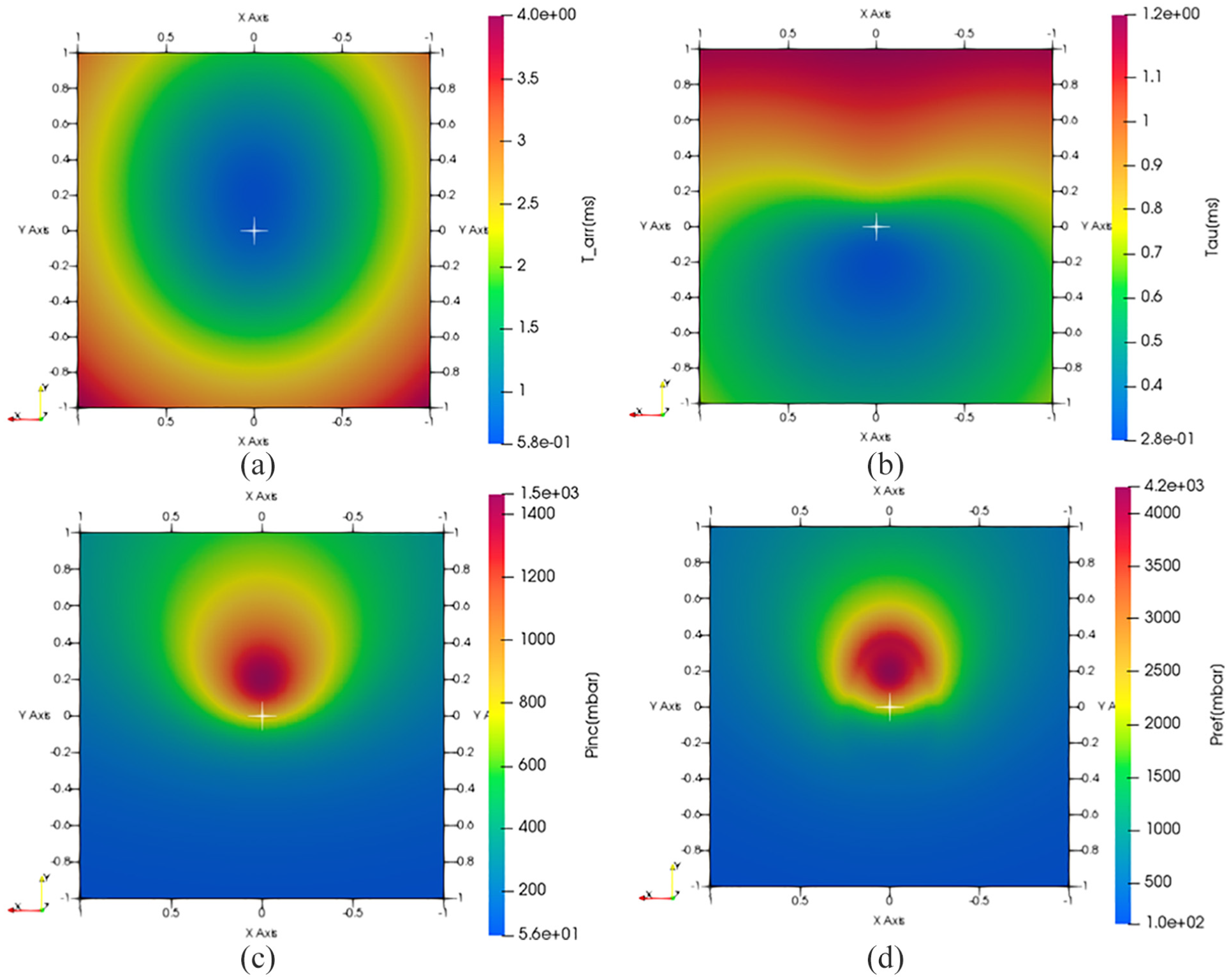
Gun blast quantities for the coupling verification. 41
In particular, those results are the contours of the time of arrival
Considering that the direction of fire is along the
The hydrocode case was set up using the LS-PrePost tool 43 and the geometrical case was created using the same dimensions of the panel of the in-house tool case. That geometry was then discretized in a mapped quadrangular mesh composed of a total number of 1600 quadrangular (square) elements (the edge is 50 mm long), because such a mesh was judged to have a reasonable accuracy. Linear SHELL elements having four nodes with a constant thickness of 2 mm were utilized.
In respect of the numerical procedure implementation, an individual load curve defining the pressure over time was applied to each element, imposing the activation time equal to the time of arrival and adopting 10 discretization points for curve specification.
In order to finalize the verification of the correct application of the gun blast load, two types of check were performed through the ANSA pre-processing tool. 44 The first is a global check consisting of the creation of the contour of the element peak overpressure obtained by extrapolating such information from the hydrocode keyword file. This contour, expressed in the international system of units (SI), is depicted in Figure 4(a) and, as can be straightforwardly understood, the distribution properly reproduces the expected one already illustrated in Figure 3(d).
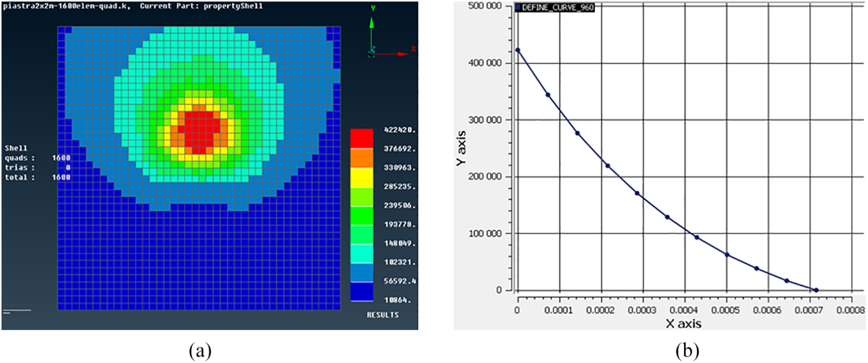
Peak overpressure map and overpressure profile of the mainly loaded element.
The second check is a local verification of the overpressure profile visualized by directly querying it through the DEFINE_CURVE functionalities. Figure 4(b) shows, for instance, the overpressure profile applied to the mainly loaded element of the case that has a peak above 4.2 bar and a positive phase duration of about 0.7 ms.
6. Results and final assessment
As earlier specified, the starting assumption for the proposed approach assessment is the availability of the experimental data of the gun. Considering the good results gained in the in-house tool validation stage and deepened by Costa and Lagasco, 33 to perform the final stage of the assessment the free field peak overpressure profiles determined applying the same input values were reliably taken as reference, that is, as if they were actually registered during a real firing test.
The following sections respectively describe the TNT charge calibration performed to enable the hydrocode simulation in the respect of the second Lagrangian approach investigated, the set-up of the hydrocode case shared between these approaches, and the computational outputs gained through them.
6.1. TNT calibration
The gun blast reference profiles, freely available on the web,
45
are shown in Figure 5(a). In particular, the free field curves ranging from 0.4 to 2.0 bar with a step of 0.4 bar are plotted in a Cartesian diagram where the abscissa and ordinate axes respectively denote the
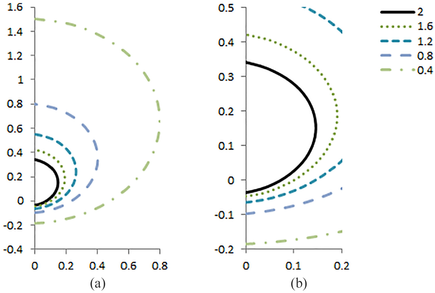
Reference free field profiles of the gun.
With the purpose to carry out the calibration in a manner independent from the muzzle firing configuration in terms of the barrel train and elevation angle, which is likely the most used choice when many firing configurations need to be simulated in a short time, the calibration of the TNT charge was carried out trying to best fit the maximum value of the available peak iso-overpressure profile. Taking this latter as target and using the relationship approximating the experimental tests 4 provided by Swisdak, 46 an equivalent mass charge of 0.274237·10–3 kg was calculated assuming 0.15 as the stand-off distance. Adopting this latter value, the peak incident overpressure plotted in Figure 6 is gained. In this image the curves concerning 0.4, 1.2, and 2.0 bar determined by means of the in-house tool and the TNT equivalent model are compared.
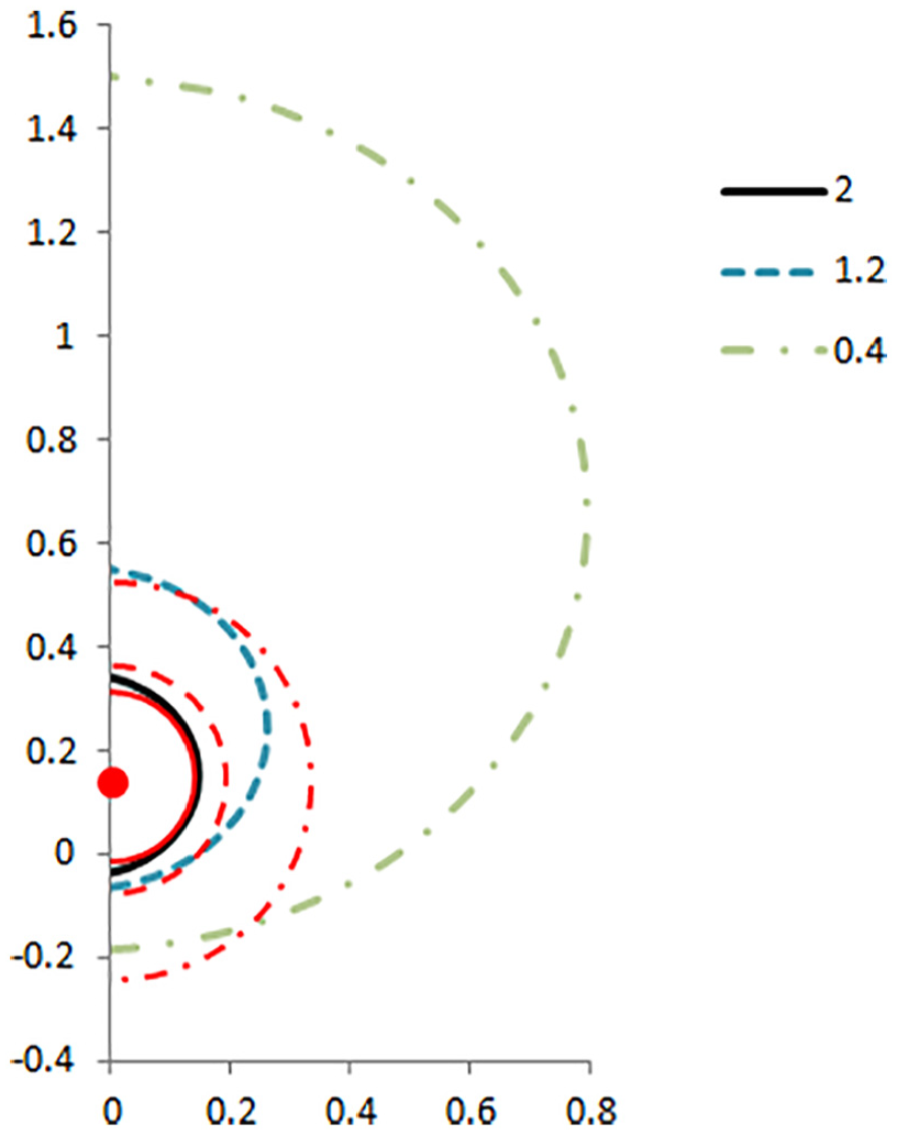
Equivalent tri-nitro-toluene charge blast wave propagation.
As can be straightforwardly understood, the target curve is well reproduced if the detonation point is shifted around at 0.15 m from the muzzle bore along the direction of the barrel (the
Given that, when the Lagrangian calculation is run adopting the TNT model, we expect to get computational estimations that substantially differ from the ones obtained through the in-house tool and, then, from the real ones. This discrepancy is hereinafter quantified in Section 7.
6.2. LS-DYNA case settings
With regard to the hydrocode case set-up, the adopted values for the physical properties of the aluminum alloy, supposed to behave according to the linear elastic material model, are summarized in Table 1, whilst for the viscous structural damping value, the best practice envisaging the use of the vibrational characteristics of the structure was employed. 47 In particular, this procedure foresees using the *DAMPING_GLOBAL card and a value for damping equal to 0.4*π/T, where T is the period of the mode targeted for damping that has been assumed as the lowest frequency natural mode of the structure.
Physical properties of the aluminum alloy used in the numerical assessment.
As far as structural constraints are concerned, the nodes belonging to the four edges of the square panel were clamped (all degrees of freedom fixed) to simulate the welded metallic panels typically used in warship construction.
With regards to the structural numerical solution, the explicit solver was utilized to calculate the transient response of the structure until 0.5 s of simulation, assuming a null prestress of the panel and that the panel deformation does not influence the pressure load distribution during simulation. Referring to the behavior of SHELL elements, the Belytschko–Tsay,48,49 shell, namely a fully integrated membrane (bending stiffness is assumed negligible), has been selected.
As earlier stated, the hydrocode cases differ only for the applied loads. As for as the empirical blast model for conventional explosive (TNT model) case, its implementation is described in detail elsewhere. 11 The *LOAD_ BLAST_ENHANCED (LBE) card 50 was adopted, assigning the spherical burst with no amplification of the initial shock wave due to the interaction with the ground surface. Due to a limitation of the release of the hydrocode used for this analysis, the option to include the reinforcement produced by the Mach front was not exploited because the final firing configuration, characterized by a stand-off distance of 0.26 m, makes the blast scenario be outside the range of validity of the model. It is worth adding that LBE is based on tables of experimental data for conventional explosions converted into approximating polynomials using classical scaling laws, and it consists of an improvement of the previously implemented approach, called the *LOAD_BLAST model, whose accuracy was evaluated by Rigby et al., 51 including some important additional options. 50
7. Results of the comparison
In the case that the blast loads are provided by the in-house tool, Figure 7 depicts the profile of the maxim value of the (von Mises) effective stress in MPa monitored in the whole mesh until 0.05 s of the simulated time. The registered peak is just below 70 MPa.
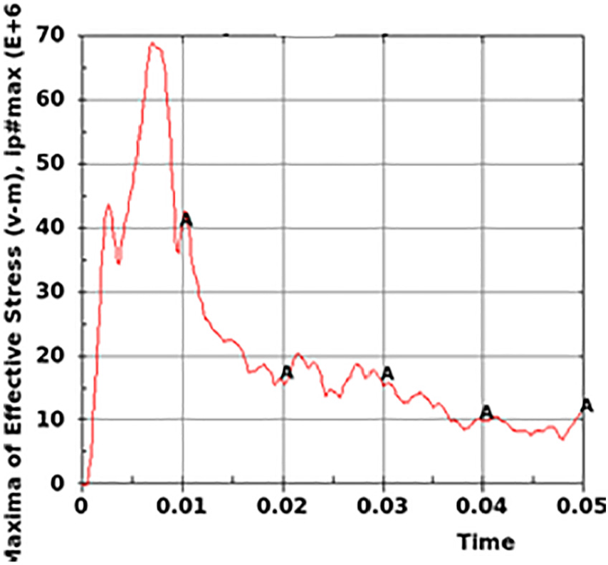
Profile of the maximum value of effective stress in the panel (in-house tool blast load).
The distribution of the (von Mises) effective stresses in the panel at different time steps of computing and expressed in pascals is depicted in Figure 8 from the top view using a fixed range from 0 to 70 MPa.
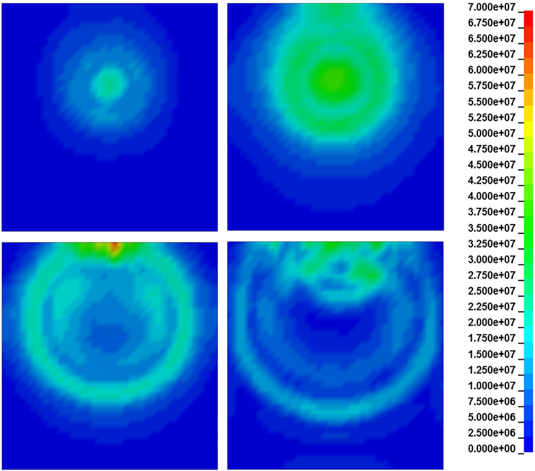
Effective stress in the panel at several simulation times (in-house tool load).
As can be seen, after the impingement of the blast wave, the distribution of the highest values of stress involves the upper part of the panel, including the clamped edge on the top of the image. Given the maxim stress value, the threshold level of 120 MPa is not passed and, then, the component maintains its structural integrity.
The effective stress distribution in the panel obtained for the case in which the blast load is computed through the TNT model is shown in Figure 9. Specifically, the simulation times are the same as those of Figure 8, except for the third, which refers to the iteration at which the maximum value for the stress of about 13.7 MPa is reached.
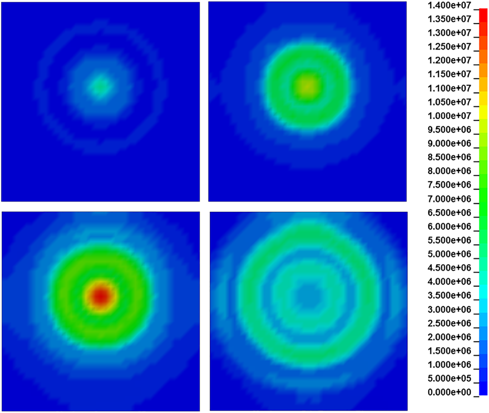
Effective stress in the panel at several simulation times (tri-nitro-toluene model load).
As can be seen, the transient distribution blast load substantially differs both qualitatively and quantitatively. On the one hand, this fact is due to the directionality of the (real) gun blast wave and, on the other hand, the different extent of the incident pressure itself.
It is worth mentioning that for the particular analyzed gun blast scenario the use of the TNT model would have led to an erroneous prediction of the stress, which is also dangerous because it underestimates the real levels.
8. Conclusions
The coupling between an in-house tool and a hydrocode to determine the stress levels in structures loaded by the blast wave emitted in ambient conditions at the firing of a cannon-type weapon system was described.
The proposed coupled approach has been verified to be coherent using gun blast loads already validated and present in the literature. Major pros and cons of the personalized coupled approach were described as well.
Using the blast loads gained through the in-house tool and TNT model, a test case was developed until the determination of the transient structural response to showcase and quantify the discrepancies in the stress prediction.
The proposed technique can be thus used to quantify the harmful effects on acceptor systems, reproducing real cases of industrial interest, such as people and structures, as well as sensitive equipment. The industrial sectors in which the presented numerical means can represent a reliable means of support for blast design are surface warships, aircraft, and ground combat systems.
Moreover, thanks to the way it was conceived, it can be also run with other computational structural mechanics (CSM) model software, providing that the loading settings of the numerical case can be tailored in some way.
Footnotes
Acknowledgements
The author thanks Prof. Marco Evangelos Biancolini of the University of Rome “Tor Vergata” for filtering the profiles of the blast data affected by noise. The author also thanks Ing. Marco Di Nonno of BETA-CAE System for support in the generation of the custom blast loads distribution.
Funding
The author received no financial support for the research, authorship, and/or publication of this article.