
Abstract
Fighter jets play a crucial role in modern combat. However, pilot training on real aircraft is costly and involves considerable risk. Regarding this issue, high-fidelity simulators have attracted increasing attention in recent years and have been widely recognized as an effective approach for reducing training expenditure and enhancing safety. Based on this background, this study develops an F-16 simulator with a particular emphasis on simulation fidelity, which is mainly achieved through two digital twin subsystems proposed in this work. For the first subsystem, a rigorous nonlinear modeling approach and publicly available NASA data are used to construct an accurate F-16 flight dynamics model. For the second subsystem, Unreal Engine (UE) and Cesium are employed to provide a highly realistic visualization of the aircraft and the virtual world. A general framework is further proposed to efficiently integrate both subsystems and several essential interfaces, including hardware joysticks and virtual reality (VR) devices, thereby providing a more comprehensive flight experience. In addition, a dedicated logging module is incorporated to enable seamless integration with the well-known analysis tool Tacview for post-mission review and debriefing. Finally, a simplified cannon-shooting training scenario is implemented, and the results indicate that the proposed simulator achieves a high level of realism and immersion.
1. Introduction
The presence of fighter jets is reshaping our conventional understanding of military doctrines. 1 These powerful aircrafts, known for their efficiency and flexibility in combat, often serve as the primary offensive force in tactical planning. Consequently, their value in defense applications is widely recognized. However, the associated costs are extremely high. Among these, the most well-known is the expense of pilot training, which can sometimes even exceed the hardware cost of the aircraft itself. At the same time, as related development technologies continue to evolve, fighter jets now carry an increasing number of advanced onboard systems to meet the diverse requirements of modern combat. These advanced hardware and software systems make flight operations more complex and further increase the difficulty of pilot training. In addition, flight training also places a strong emphasis on the pilot’s response to dangerous situations, which often requires a great deal of practice to ensure that the pilot can react correctly in real-life emergencies. However, due to safety concerns, the relevant training will be adapted or simplified in the real world, which will reduce the pilots’ response sensitivity. Because of the physical limits of both aircraft and pilots, it is also difficult to repeatedly conduct real-world flight training under specific conditions, such as flying through clouds, performing instrument flight in severe weather, chasing moving targets, or evading missile lock. In summary, although live flight training for pilots is essential and cannot be fully replaced, it is also associated with high costs and significant risks, and its training efficiency is not always ideal. Therefore, there is a clear need for an auxiliary training method that helps reduce these costs while improving overall training efficiency. Among the various auxiliary training approaches, high-fidelity flight simulators have received growing attention in recent years. For example, in modern defense training architectures such as Live, Virtual, and Constructive (LVC), these realistic simulators serve as core components and play a key role in the overall training process.2,3 Moreover, many studies4–7 have revealed that introducing simulators into the training process can provide substantial benefits in reducing costs and risks and ensure training effectiveness at the same time.
In recent years, simulators for training purposes have developed rapidly. To provide a higher level of immersion, simulators are often integrated with virtual reality (VR) devices, and related research and practical applications have attracted considerable attention.8–11 In flight-training scenarios, such systems can offer users a more comprehensive view and experience, which can help improve training effectiveness.4,12 Furthermore, when mixed reality (MR) technology is integrated into simulators, it can help reduce cybersickness and improve the quality of interaction between users and physical hardware in the real world.13,14 Such immersive simulators can also be used for tactical and medical training,15–18 providing concrete and practical support in many other domains.19–21 In fact, simulators are not limited to training purposes. Taking reinforcement learning, a field that has become very popular in recent years, as an example, one key step is to use appropriate high-precision modeling methods to construct a detailed model of how an agent interacts with its environment. In this way, we can build a virtual environment that supports a large number of repeated trials and training, which can essentially be regarded as a type of simulator.22–24 Such a simulator helps avoid the low efficiency and high cost that may arise when reinforcement learning algorithms are developed and tested directly on real systems.
Regarding this study’s focus on supporting fighter pilot training in defense applications, our main concern is how realistic the simulator can be. If the level of realism is insufficient, the gap between the simulator and actual flight becomes larger, which may reduce training effectiveness. Actually, the simulator’s realism is dominated by two main aspects. The first is the establishment and validation of a high-precision flight dynamics model, so that the aircraft’s response can be accurately reproduced. The second is the presentation of a highly realistic virtual environment. In this study, these two aspects are directly reflected in the two proposed subsystems based on the digital twin concept.25–28
The first digital twin subsystem aims to accurately establish the mapping relationship between command inputs and the fighter aircraft’s dynamic responses. In this study, a high-precision nonlinear modeling method,29,30 combined with parameters given in the NASA technical report, is used to construct an accurate dynamic model of the F-16 fighter and its corresponding angular velocity controller in MATLAB. The responses of this model are then examined through multiple simulated flight maneuvers to confirm its validity. In this way, the model can more accurately capture the aircraft’s behavior under different flight conditions than oversimplified models. As for the second digital twin subsystem, it focuses on reconstructing a highly realistic environment. Unreal Engine (UE), which is known for its high-fidelity rendering capability, is adopted as the core of the proposed simulator, and Cesium is also integrated to provide a high-resolution global map in real time, thereby creating a virtual environment that closely matches real flight scenarios. Furthermore, this study proposes a general framework based on C++, deeply integrating these two digital twin subsystems in a modular way. MATLAB Coder is used to convert the first digital twin subsystem into C++ code, which is then encapsulated as a DLL file and seamlessly integrated into the proposed framework as the dynamics module. Within this framework, both hardware joystick input and VR display are also well organized. Joystick signals are sent to the dynamics module described above for real-time flight state computation, and the rendered views are streamed to VR devices, providing users with a panoramic view for a more realistic flight experience. In addition, this study implements a logging module within the proposed framework to record flight states, enabling the simulator to integrate with the well-known flight analysis tool Tacview for post-mission review and debriefing. Thanks to the modular design of the proposed framework, a high-fidelity simulator for a new fighter jet or other vehicle can be built rapidly by just defining the corresponding dynamic model and visualization components within it, which further demonstrates the framework’s portability.
The remainder of this article is organized as follows: Section 2 describes the F-16 flight dynamics modeling and the corresponding control law design. Section 3 presents the validation results of the proposed model. Section 4 introduces the high-fidelity virtual environment built upon UE and the overall integration framework. Finally, Section 5 presents the conclusions and future work.
2. Flight dynamics modeling and control design
To achieve a high-fidelity flight experience, one key design task is to develop a complete mathematical dynamic model of the fighter aircraft, which serves as the basis of the first digital twin subsystem in this work. In this section, the primary objective is to build an angular velocity control system for the fighter. The control system consists of two main parts: system modeling and controller design. First, system modeling constructs a mathematical model that accurately describes the behavior of the aircraft, which provides the basis for controller design and strongly affects the realism of the flight experience. Second, based on this aircraft model, a nonlinear angular velocity controller is designed to achieve the angular velocity targets specified by the pilot’s joystick input.
Figure 1 shows the structure of the angular velocity control framework. The angular velocity command
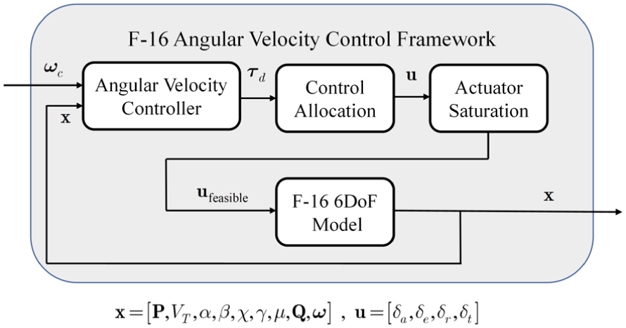
F-16 angular velocity control framework.
To model the aircraft precisely, the F-16’s aerodynamic model, engine model, and atmosphere model provided in NASA Technical Report TP-1538 31 are used in this study to ensure the accuracy of the simulation. Fighter F-16 was chosen as an example model because the data are sufficient and publicly available, allowing this study to focus on the design of a framework for the development of a high-fidelity simulator platform that is highly scalable and can be easily applied to other aircraft types in the future.
The rigid-body dynamics model encompasses both translational and rotational motions, which will be described by Newton’s second law and Euler’s equations, respectively. Moreover, unlike typical ground vehicles, fighter jets often execute aggressive maneuvers in the air. Therefore, aerodynamic forces and moments must be considered in the model to accurately represent the vehicle’s motion.32,33 For fighter aircraft, force equations are typically formulated in the wind-axis coordinate system, and this modeling choice is especially important when flying at a high angle of attack while simultaneously executing rolling maneuvers.34,35
2.1. Fighter aircraft equations of motion
To exhibit the behavior of fighters in the simulator, the aircraft states must be obtained by the dynamics model. The aircraft states include position
2.1.1. Position state equation
The position vector

where
2.1.2. Airspeed state equation
The airspeed
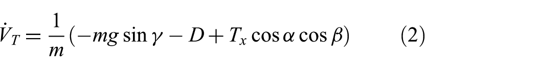
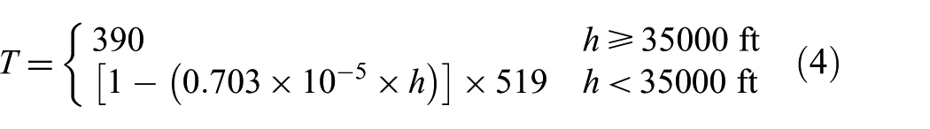
where
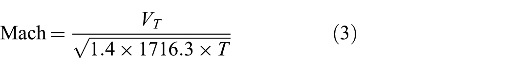
where temperature
2.1.3. Heading angle state equation
The heading angle
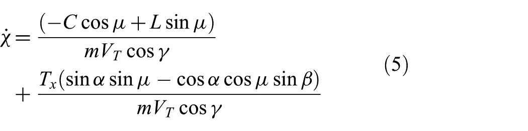
where
2.1.4. Flight path angle state equation
The flight path angle
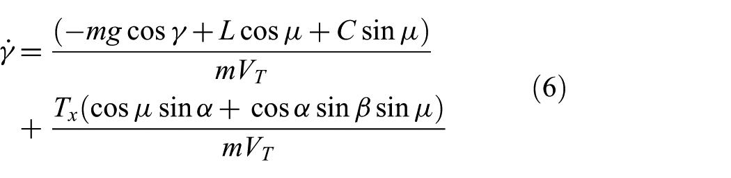
The above state equations for airspeed, heading, and flight path angle can be proved by applying the force equations in the wind-axis frame. As for the state equations for velocity roll, angle of attack, and sideslip angle, they can be derived using the angular velocity relationship between the global and body frames. All of these derivations are provided in detail in Appendix 1.
2.1.5. Velocity roll angle state equation
The velocity roll angle
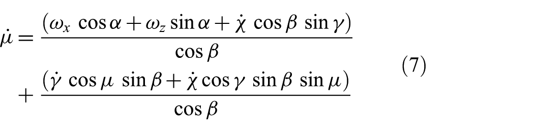
where
2.1.6. Angle of attack state equation
The angle of attack
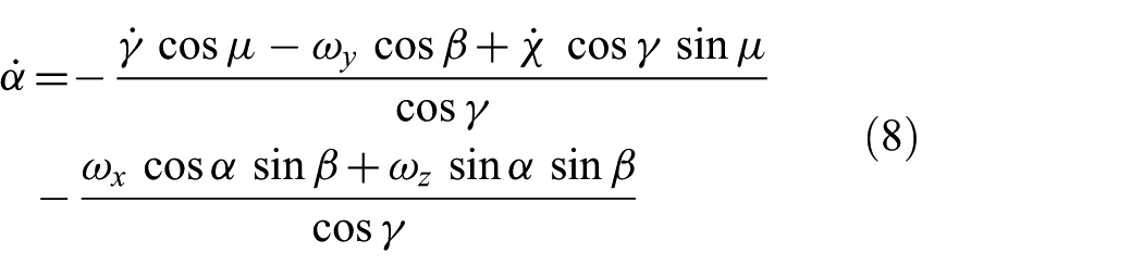
where
2.1.7. Sideslip angle state equation
The sideslip angle

The inputs to the state equations above include the control surface deflection angles and the throttle setting. The corresponding aerodynamic and engine models are then used to compute the aerodynamic forces and engine thrust. Using Equations (1)–(9), the position of the aircraft in the global frame can be obtained.
2.2. Attitude state equations
The aircraft attitude will be represented with the quaternion
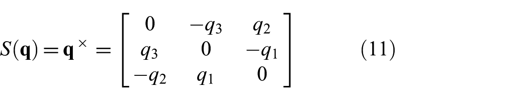
2.2.1. Quaternion state equation
The quaternion
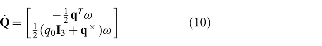
where
2.2.2. Angular velocity state equation
The angular velocity vector

where
2.3. Design of angular velocity controller
It is known that the commands from the pilot’s joystick are angular velocities, and in order for the aircraft to track these angular velocity commands, it is necessary to build a closed-loop control system and the corresponding angular velocity controller, as shown in Figure 1. With this controller, the aircraft can achieve stable and accurate angular velocity tracking, enabling it to execute the planned flight maneuvers.
First, establish the error equation for angular velocity:

where

The above equation is an error state equation, which can be transformed into a linear form by designing an appropriate control law. Once it is converted into a linear form, the system analysis and controller design become much simpler. Therefore, in this study, the control law is designed as follows:
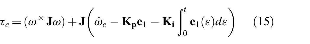
This control law includes the nonlinear feedback compensation, command feed-forward, and the proportional–integral (PI) controller, where
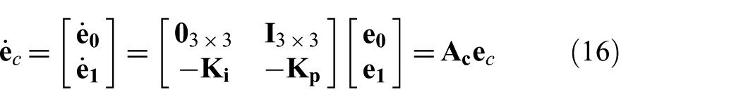
After designing the corresponding control law, the closed-loop stability must be analyzed. In this study, the stability is ensured by designing the control gain
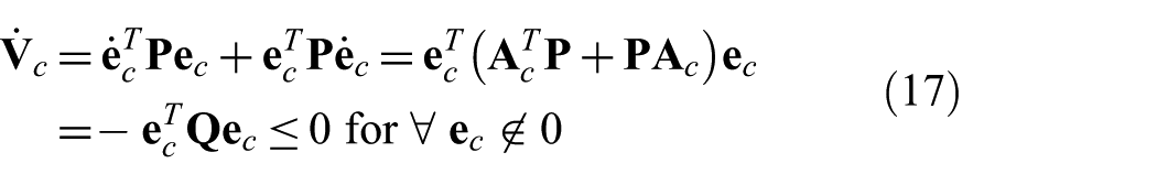
From the above equation, the closed-loop system is guaranteed to be asymptotically stable as long as
2.4. Fighter control surface allocation
Based on the angular velocity controller design described above, the controller computes the moments required to achieve the desired angular velocity. To realize the desired moments, the aircraft must actuate its control surfaces. Therefore, this study introduces a control allocation law that maps the desired moments to the deflection angle commands of each control surface. In addition, actuator saturation is taken into account, as shown in Figure 1, so that the generated deflection commands are more consistent with real flight conditions.
The aerodynamic moments in the direction
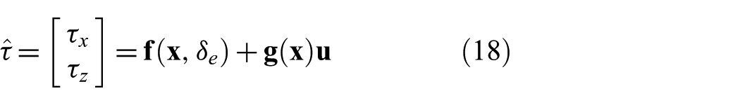
where

where
To solve for the elevator deflection angle command independently, the bisection method is used. For Equation (19), define an error function:

where

After obtaining the elevator deflection angle command, substitute it into the following equation to solve for the deflection angle commands of aileron and rudder.

Once the control surface deflection angles are all obtained from the control allocation law, they are sent to the corresponding actuator models with saturation. The resulting constrained outputs are then fed into the fighter’s 6DoF dynamic model to generate realistic simulated flight states.
3. Simulation results and evaluation
Following the controller design described above, the simulation results presented below focus on examining whether the relationships among the desired command inputs, the angular velocity control responses, and the corresponding control surface deflections are reasonable. As mentioned above, to make the simulation more realistic, this study further incorporates the actuator dynamics of the control surfaces, 31 as shown in the following equation.
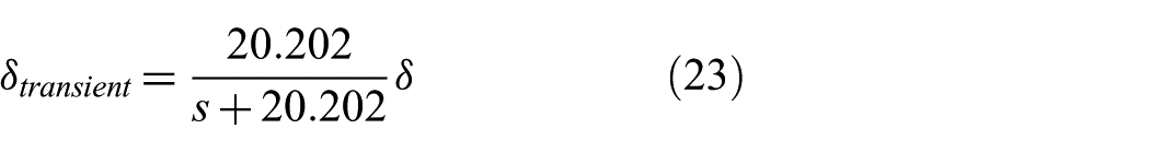
where
Since fighter aircraft often executes high-bandwidth, aggressive maneuvers, an insufficient sampling rate may distort the model response and degrade model fidelity. To avoid this, the simulated states are propagated at 1 kHz using a classical fourth-order Runge–Kutta (RK4) scheme.
3.1. F-16 pure rolling maneuver simulation
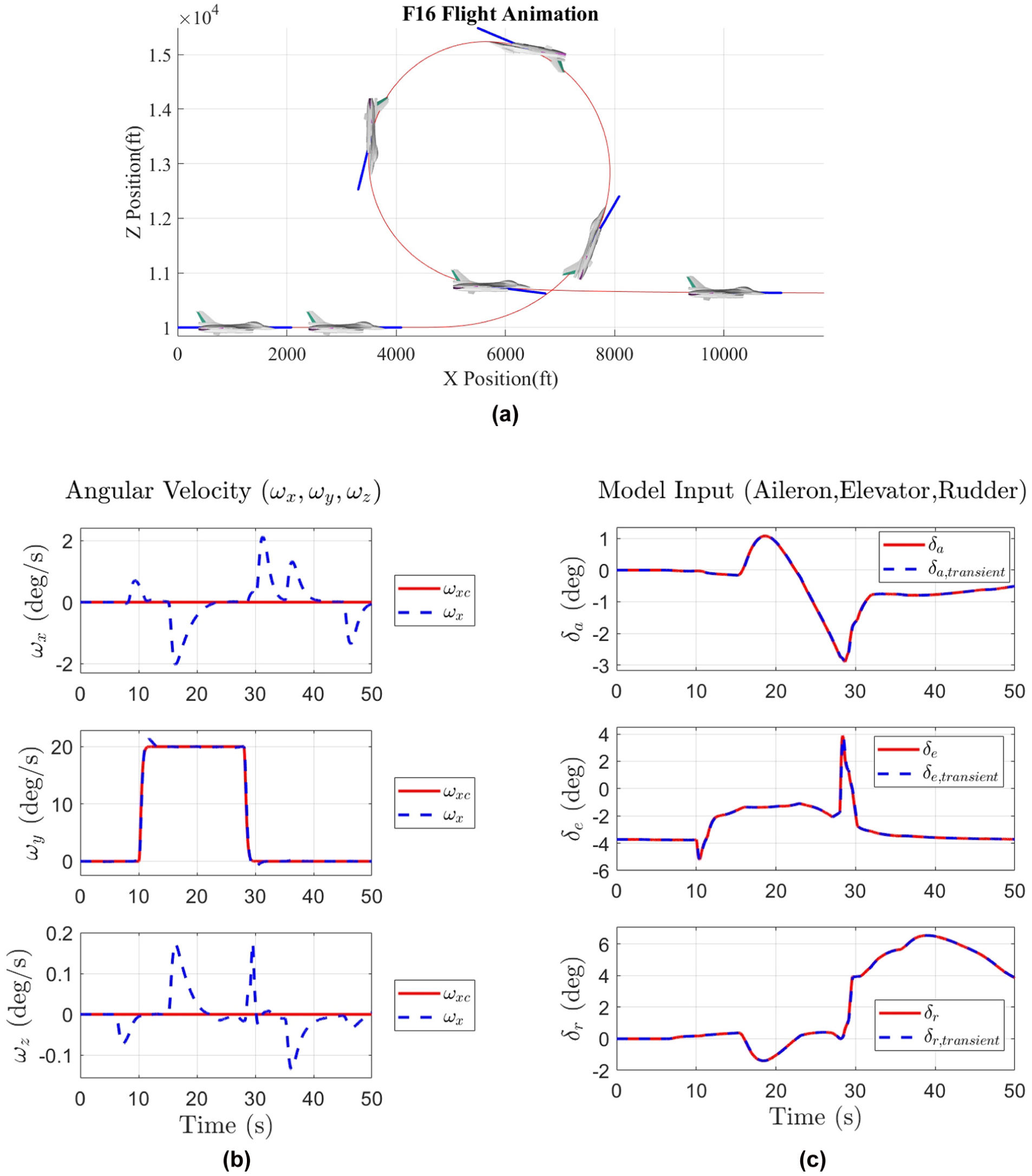
Rolling maneuvers are an important part of high-agility flight. In this simulation test, a 180 deg/s roll rate command is applied as an extreme test condition, while the pitch and yaw rate commands are kept at zero. Figure 2(a) shows the overall flight simulation, where the blue arrows indicate the velocity direction of the aircraft. In Figure 2(b), the red curve denotes the commanded roll rate, and the blue curve shows the actual roll rate response of the aircraft. Figure 2(c) presents the responses of the control surfaces, in which the red curves represent the desired deflection angles, and the blue curves indicate the actual deflection angles after considering the actuator dynamics. From these results, it can be clearly seen that the desired roll rate in Figure 2(b) is well tracked, which confirms the effectiveness of the controller design in this study. Because the actuator dynamics are included, the transient response of the control surfaces prevents the desired moments from being realized immediately, leading to small oscillations in the control results. Nevertheless, the corresponding tracking errors remain small and within an acceptable range.
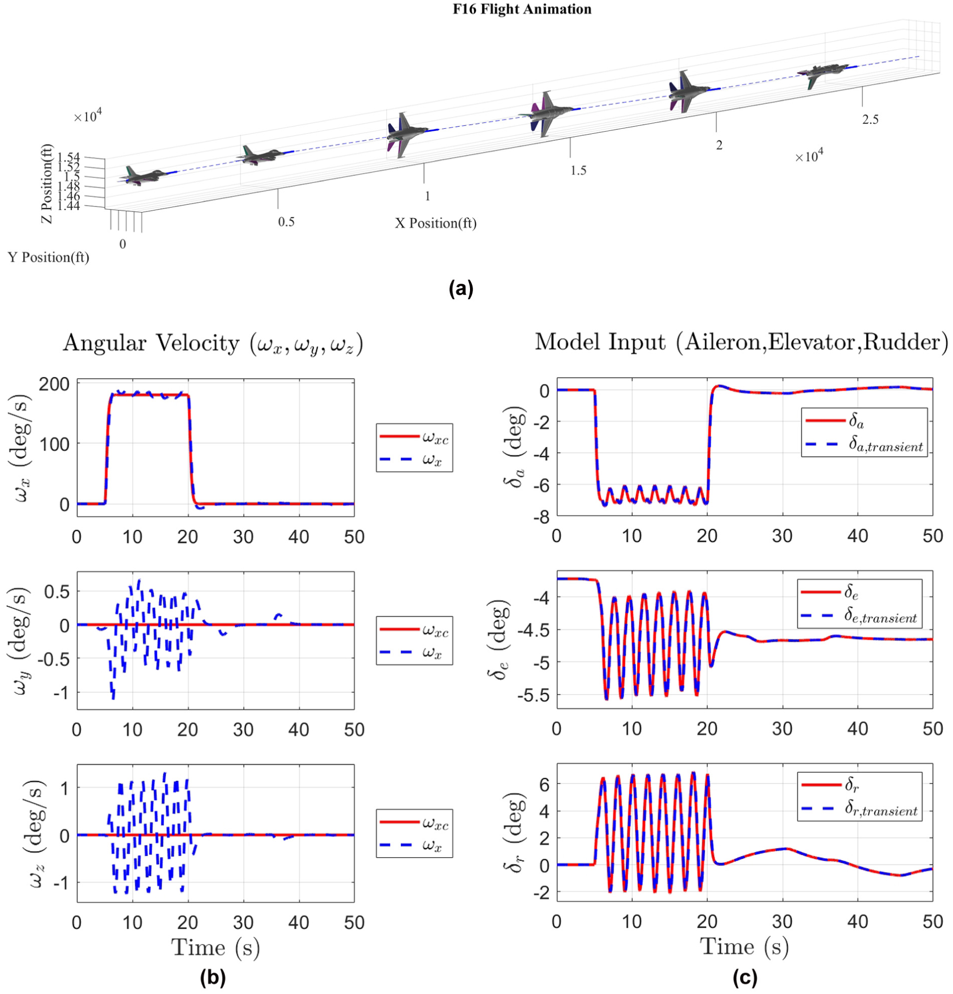
Simulation results for a pure rolling maneuver. (a) Flight trajectory responses. (b) Angular velocity responses. (c) Control surface responses.
3.2. F-16 pure pitching maneuver simulation
Following the pure rolling maneuver simulation, a pure pitching maneuver is then considered. To examine whether the model response remains reasonable under extreme conditions, this test applies a fairly aggressive 20 deg/s pitch rate command, while the other commands are kept at zero. Figure 3(a)–(c) shows the corresponding simulation results. As seen in Figure 3(b), the model tracks the pitch rate command closely, and some oscillations appear in the responses as well, arising from the same cause as in the previous case.
Simulation results for a pure pitching maneuver. (a) Flight trajectory responses. (b) Angular velocity responses. (c) Control surface responses.
In an actual pure pitching maneuver, a stall can be triggered quite easily. To observe this behavior more clearly, this test, additionally presents the time responses of several key state variables, including airspeed, angle of attack, and sideslip angle, as shown in Figure 4(a) and (b). From these figures, it can be observed that the angle of attack becomes very large and the airspeed drops sharply at around 10 s. This rapid loss of speed corresponds to a large increase in drag and is a typical sign of stall. Based on the above analysis, the results also reveal that the proposed F-16 dynamic model can accurately capture the aircraft’s response under extreme flight conditions, including near-stall behavior.
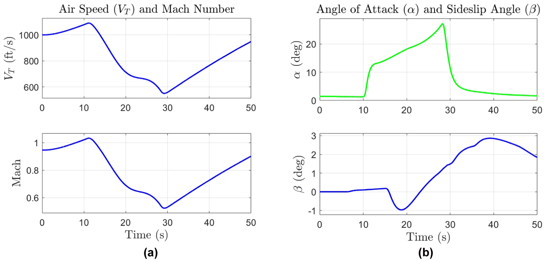
Responses of airspeed, angle of attack, and sideslip angle for the pure pitching maneuver test. (a) Airspeed responses. (b) Angle of attack and sideslip angle responses.
3.3. F-16 pure yawing maneuver simulation
In this test, a pure yawing maneuver is simulated by applying a 3 deg/s yaw rate command, with the other commands kept at zero. The corresponding simulation results are shown in Figure 5(a)–(c). As shown in Figure 5(b), the aircraft is able to track the yaw rate command, while small tracking errors still remain. At the same time, Figure 5(c) shows that the rudder deflection is saturated between about 15 and 30 s. Overall, these results clearly indicate that a 3 deg/s pure yaw rate is the limit that this aircraft can achieve. It is also worth noting that, to generate a positive yaw rate response, the rudder deflection should be negative. However, the resulting yawing motion also induces an additional positive rolling moment. To maintain a pure yawing motion, the flight controller, therefore, applies a positive aileron deflection to cancel this accompanying effect. These behaviors are consistent with the simulation results shown in Figure 5(c) and further demonstrate that the control allocation algorithm used in this study is accurate and reliable.
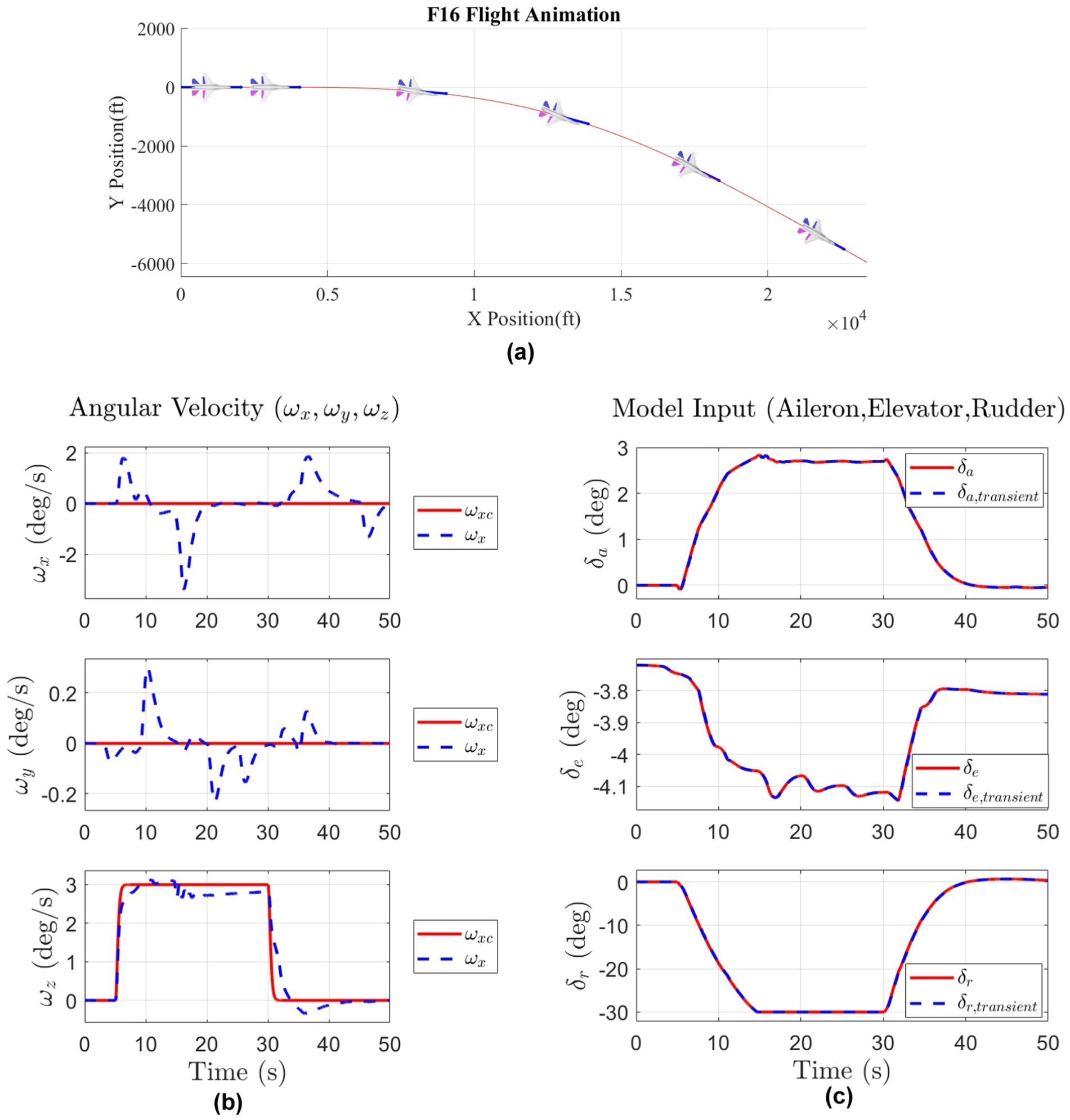
Simulation results for a pure yawing maneuver. (a) Flight trajectory responses. (b) Angular velocity responses. (c) Control surface responses.
3.4. F-16 figure-eight flight maneuver simulation
In actual flight, most high-agility maneuvers are achieved by applying roll rate and pitch rate commands simultaneously. Following the previous single-axis tests, both roll rate and pitch rate commands are set as shown in Figure 6(b), which corresponds to a figure-eight flight trajectory. The simulation results are shown in Figure 6(a)–(c). It can be seen that the aircraft tracks the commands quite well, and the tracking errors remain within an acceptable range. In addition, Figure 6(c) shows that no saturation occurs in the control surface deflections. These observations show that the proposed model has good tracking performance under a scenario that matches typical fighter operations.
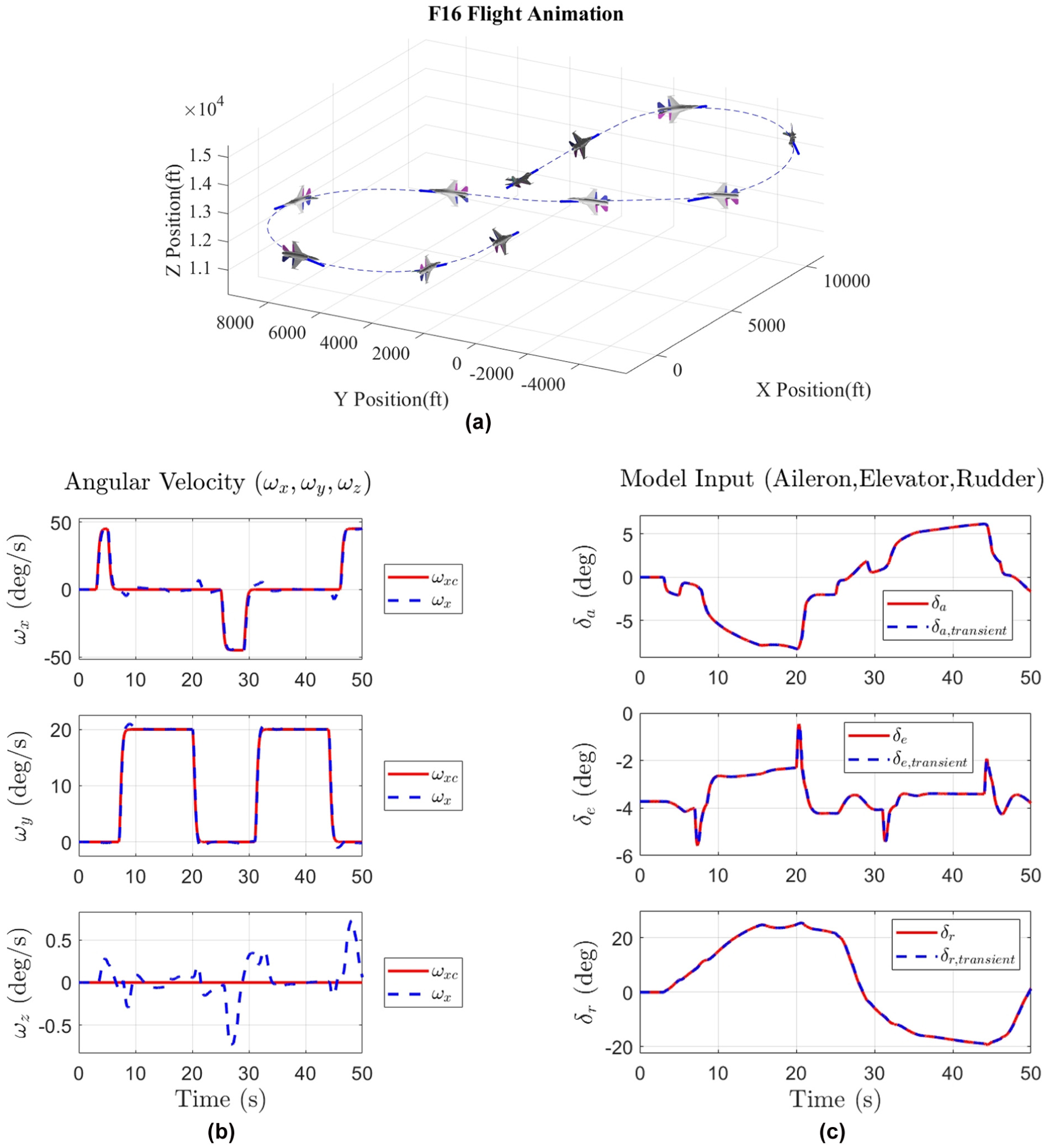
Simulation results for a figure-eight flight maneuver. (a) Flight trajectory responses. (b) Angular velocity responses. (c) Control surface responses.
In this section, the proposed F-16 fighter dynamic model is validated through several tests. The results confirm that the model can accurately capture various physical properties of the real aircraft and can, therefore, serve as a solid foundation for the high-fidelity simulator emphasized in this study. With this, the first digital twin subsystem, which is responsible for describing the aircraft’s dynamic behavior, has been completed. The next section will focus on how the second digital twin subsystem and the proposed framework handle high-fidelity visual presentation and the modular integration of these two subsystems.
4. High-fidelity visual rendering using Unreal Engine
This section focuses on the second digital twin subsystem and the overall integration framework. A key issue here is that the choice of base platform strongly affects how the development workflow is organized and the final simulator’s performance. Therefore, before selecting a suitable platform, this study first identifies the relevant requirements, which are summarized as follows.
High-Efficiency Execution: The flight dynamics model requires strict real-time performance, and an insufficient sampling rate may degrade the accuracy of the aircraft response. Therefore, the target platform is expected to support C-based languages, which offer higher execution efficiency.
Hardware Joystick Interface: The platform must support a hardware joystick so that operator commands can be smoothly passed to the F-16 dynamic model.
VR Devices Support: In real missions, fighter pilots regularly scan the surroundings to obtain a panoramic view, which cannot be achieved with a conventional 2D display. Therefore, the platform should support VR devices to provide such an experience.
High-Fidelity Visual Rendering: To ensure the realism and immersion of the simulator, the platform should be equipped with realistic visual rendering capabilities.
Finally, this study adopts UE, a game engine based on C++, as the primary development platform, which aligns well with the above specifications. UE is well-known for its powerful rendering capability,39,40 which is highly consistent with the high-fidelity objective pursued in this study. It has been widely used in simulators that demand highly realistic visual effects, such as the well-known AirSim 41 and CARLA 42 simulators, which are commonly used in autonomous driving research, as shown in Figure 7. In summary, by leveraging UE’s powerful capabilities, the quality of the visual presentation and the subsequent integration process can be strongly guaranteed, thereby further enhancing the overall realism and immersion of the resulting simulator. Following the above discussion on UE, the next section will present the overall framework design, which integrates the two digital twin subsystems and all required interfaces.
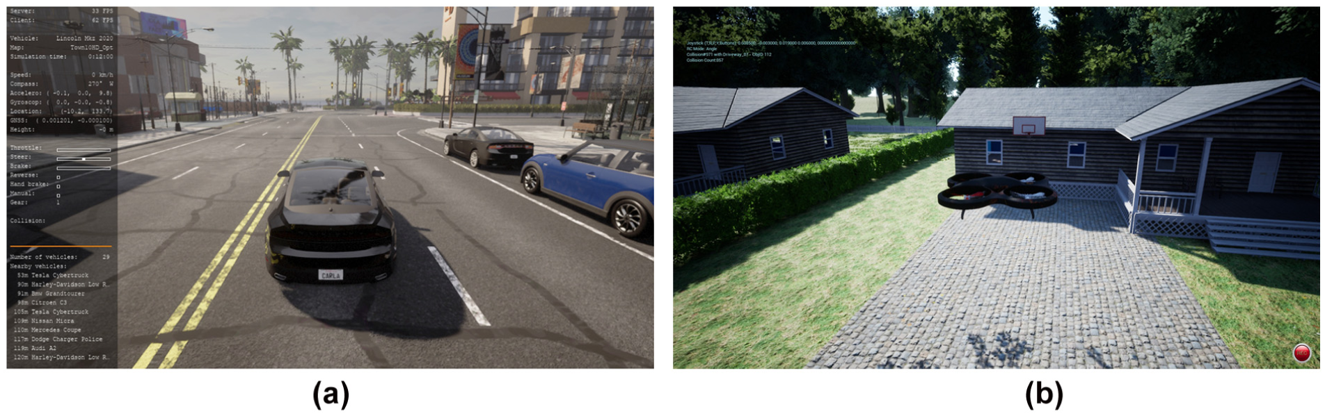
Well-known simulators based on UE. (a) AirSim simulator. (b) CARLA simulator.
4.1. Simulator framework overview
Figure 8 illustrates the overall simulator framework used in this study. The framework integrates the two proposed digital twin subsystems. The first subsystem focuses on the highly nonlinear dynamics of the F-16, as discussed in the previous section, while the second subsystem is responsible for establishing and rendering highly realistic scenes. Within this framework, the dynamics model is first constructed and validated in MATLAB and then converted into C++ using MATLAB Coder. This conversion facilitates seamless integration with UE as the dynamics module and ensures reliable real-time execution. To follow a modular design, the generated C++ dynamics functions are further encapsulated into a DLL file, which greatly improves maintainability and extensibility. Using the Windows RawInput plugin, hardware joystick inputs (angular velocity commands and throttle setting) are captured and sent to the dynamics module for high-precision simulation of aircraft pose and control surface deflections. Based on these simulated states, the UStaticMeshComponent associated with the fighter APawn instance is updated to animate the corresponding aircraft motion, while the motion of the in-cockpit control set (stick, throttle, and rudder pedals) is rendered directly from the raw joystick signals. In addition, UCameraComponent instances are mounted both inside the cockpit and outside the aircraft to provide first-person and third-person perspectives. These views are then rendered and streamed to the VR headset via Meta Quest Link, while global terrain is supplied in real time using the Cesium for Unreal plugin, resulting in a highly immersive flight experience. A dedicated flight logging module is also included in the framework to export flight data in a specific CSV format, enabling seamless integration with the well-known analysis tool Tacview for post-mission review and debriefing. Owing to the modular design of the proposed framework, the system achieves strong portability and extensibility, which will be demonstrated through the validation results in the following section. Finally, although flight evaluation is not the main focus of this study, a custom scoring module can be incorporated in the future due to the framework’s strong extensibility. As indicated by the dashed box in Figure 8, this scoring module is an optional, scenario-dependent component and is shown only at the conceptual level to complete the overall framework illustration.
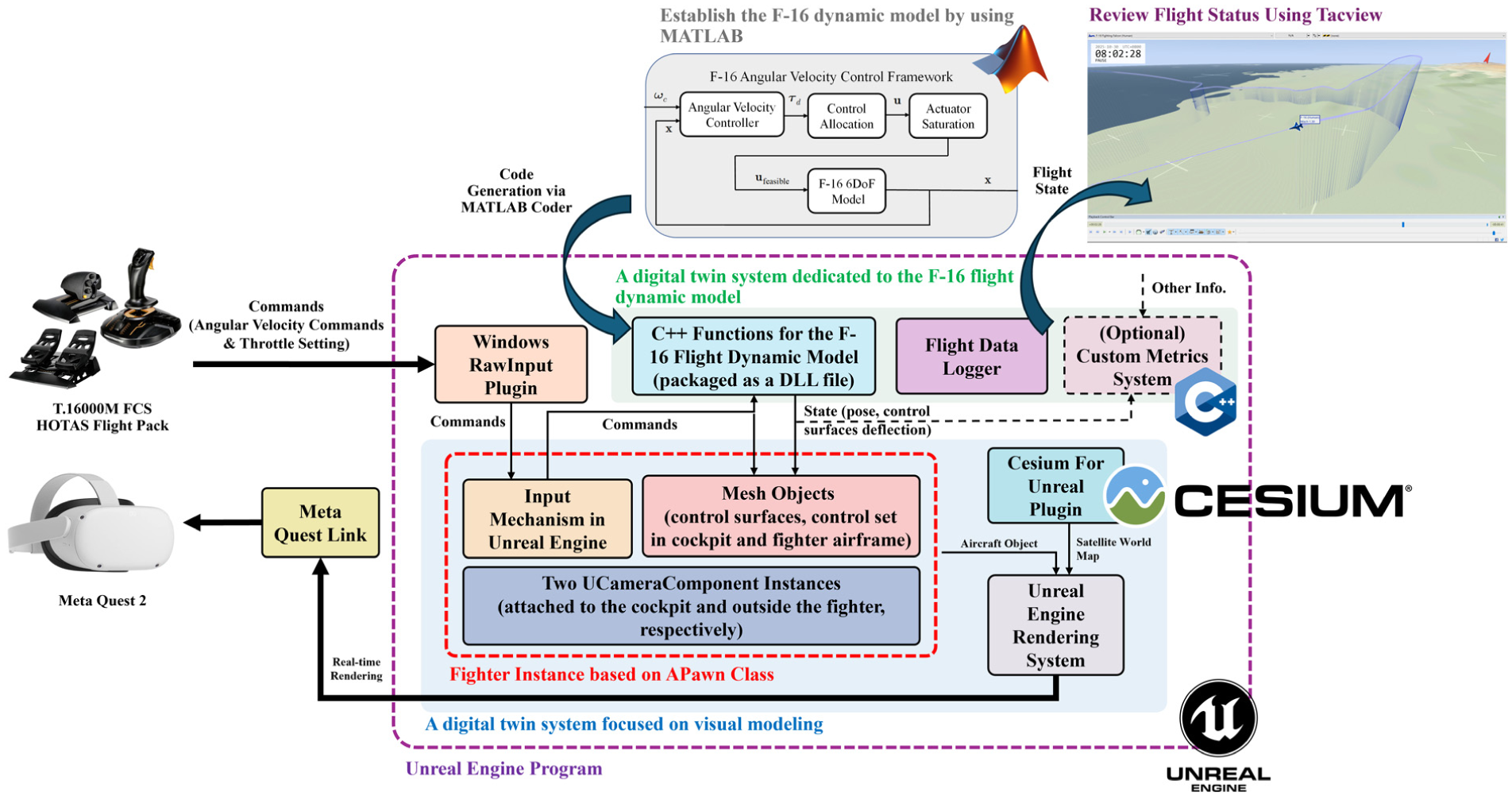
The proposed development framework.
4.2. High-fidelity scene construction
The second digital twin subsystem is dedicated to constructing a realistic scene that includes the F-16 fighter jet and the virtual environment. Within the UE development workflow, the visualization of the virtual fighter is implemented as an APawn instance. To animate the aircraft’s motion, we first define the hierarchical relationships among the static mesh components in this APawn to establish the correct transformation chain between meshes. These meshes are organized and edited through Blueprints, as shown in Figure 9(a). When the dynamics module outputs the latest aircraft states, including the pose and control surface deflection angles, the position and orientation of the fighter APawn are updated accordingly, and the associated control surface meshes are animated to reflect the corresponding deflections, as illustrated in Figure 9(b)–(d).
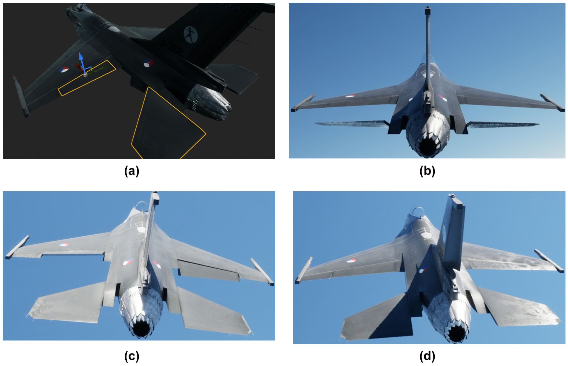
Control surface deflections of the virtual F-16 fighter jet. (a) Editing the control surface meshes via Blueprints. (b) Elevator deflection. (c) Aileron deflection. (d) Rudder deflection.
Inspired by flyscript, 43 the UChildActorComponent class is employed to enhance the maintainability of the system. The use of UChildActorComponent enables the complex visualization components to be developed and validated independently. Following this design principle, both the cockpit and nozzle visualization components are constructed and attached to the fighter APawn. In the virtual cockpit, the corresponding joystick is animated according to the raw command inputs from the hardware joystick, as shown in Figure 10, using the same mechanism as the control surface animation described above. For the nozzle visualization component, the implementation is adapted from flyscript. 43 The nozzle expands and contracts according to the throttle setting and triggers the afterburner flame effect with shock diamonds when the throttle exceeds 0.77, as shown in Figure 11.
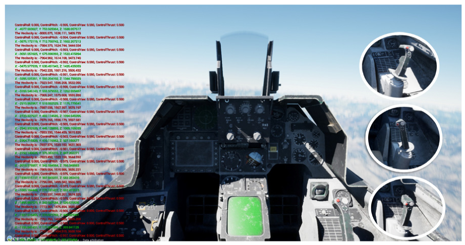
Virtual F-16 cockpit (F-16A block 15 cockpit mesh is taken from CGTrader 44 ).
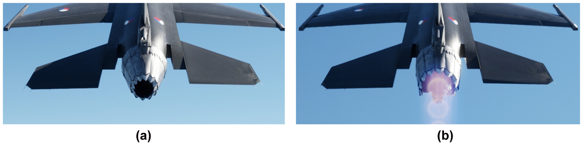
Animation of the virtual nozzle. (a) Before activating the afterburner. (b) After activating the afterburner.
In addition to the F-16 fighter jet, constructing realistic surroundings is a key element of the second digital twin subsystem. In this study, Cesium is adopted to provide a high-resolution global map, which can be easily integrated into the UE project by installing the Cesium for Unreal plugin. It is worth noting that Cesium supports various realistic lighting conditions and flexible initial position configuration, as illustrated in Figures 12 and 13, respectively. These features are highly beneficial for creating diverse mission scenarios for pilot training.
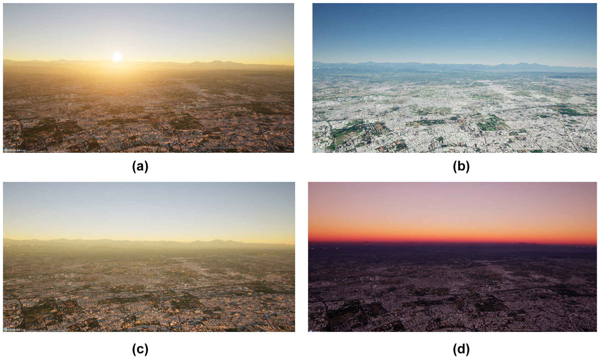
Different lighting conditions generated in Cesium, with the camera located at 585 m above the Department of Aeronautics and Astronautics, National Cheng Kung University, Tainan, Taiwan. (a) 7:00 AM. (b) 12:00 PM. (c) 6:40 PM. (d) 7:00 PM.
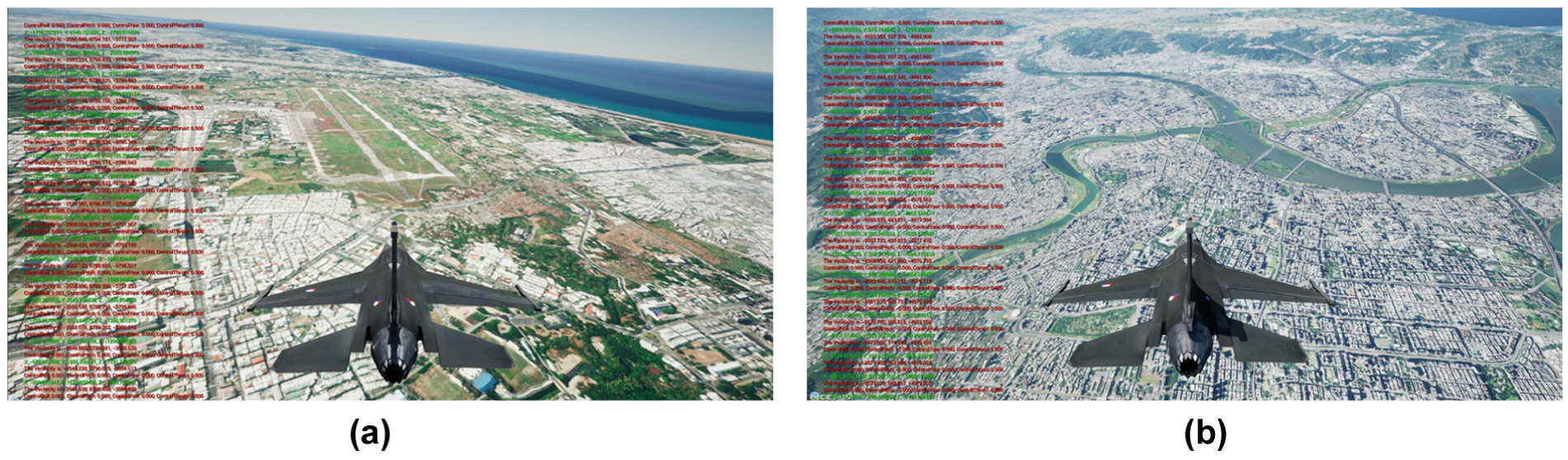
Different initial aircraft position settings in Cesium. (a) Tainan, Taiwan. (b) Taipei, Taiwan.
This study, in addition, uses the volumetric cloud system provided by UE to render various types of clouds, as shown in Figure 14(b) and (c). In this way, typical scenarios involving a fighter flying above the clouds can be realistically simulated, as illustrated in Figure 14(a).
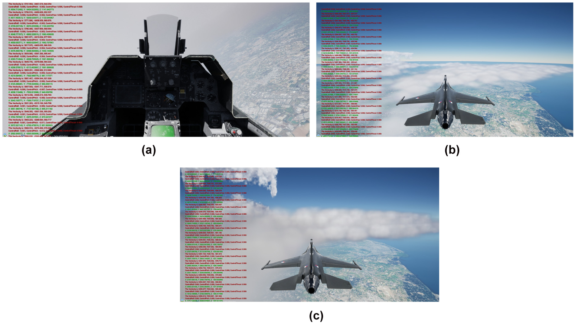
Cloud creation and configuration using the volumetric cloud system. (a) Virtual fighter jet flying above the clouds in the proposed simulator. (b) Thin clouds. (c) Dense clouds.
To further verify the potential of the proposed simulator to support various customized training tasks, this study, in addition, develops a simplified virtual cannon-shooting scenario for training pilots in basic aircraft control and gun-aiming skills. In this scenario, virtual cannon bullets are created using the A Actor instances, and mesh-overlap detection is employed to determine whether each bullet collides with any object. Once a collision is detected, the simulator triggers the corresponding impact effect, as illustrated in Figure 15(a). Multiple targets are randomly placed, and each target is programmed to explode and be removed from the scene after it has received 30 bullet hits. Figure 15(b) illustrates the operator performing the resulting virtual training scenario with a joystick and a VR device, further confirming the simulator’s flexibility in supporting customized training tasks. This demonstration also clearly shows that the two proposed digital twin subsystems and the integration framework can indeed create a highly realistic flight-training environment.
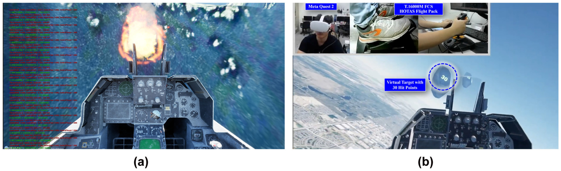
Constructing a simplified virtual cannon-shooting scenario in the proposed simulator to verify its flexibility in creating customized training tasks. (a) Bullet impact effects triggered by enabling mesh-overlap detection. (b) Virtual training in a cannon-shooting scenario using a joystick and a VR device.
Besides, a practical simulator should record flight states for subsequent analysis and debriefing, aligning with real training practice. Accordingly, our framework incorporates a dedicated logging module, as shown in Figure 8. This module exports flight data in a specific CSV format, thereby enabling seamless integration with Tacview, a well-known flight analysis tool. With Tacview, we can replay full missions, inspect trajectories from multiple viewpoints, and pause at any time for detailed review, as illustrated in Figure 16.
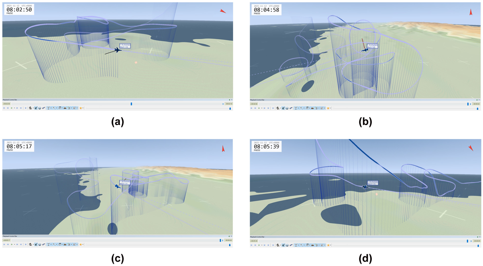
Mission replay and debriefing via Tacview integration. (a) Flight Trial 1. (b) Flight Trial 2. (c) Flight Trial 3. (d) Flight Trial 4.
In summary, the above results show how we use UE to build the second digital twin subsystem, which focuses on creating highly realistic environments and user interaction. These results also indicate that the proposed simulator achieves a high level of realism and can provide users with an immersive and high-quality flight-training experience. These high-fidelity capabilities can be largely attributed to the two digital twin subsystems and their efficient integration through the proposed framework, as illustrated in Figure 8. In addition, based on the modular design of the proposed framework, another simulator with comparable fidelity can be developed simply by replacing the dynamics model and its corresponding visualization components. As illustrated in Figure 17, the same framework is used to construct a realistic drone simulator, which further demonstrates the strong portability of the proposed framework.
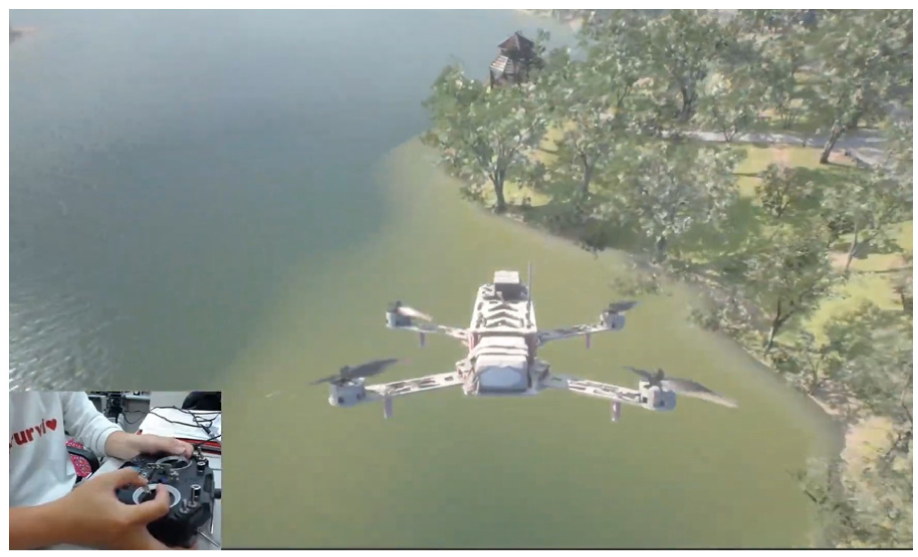
Construction of a drone simulator using the proposed framework. (The drone visual 3D model is taken from freakering 45 ).
5. Conclusion
Using simulators to support fighter training clearly reduces both cost and risk. Building on this advantage, this study presents a high-fidelity simulator composed of two proposed digital twin subsystems. The first subsystem is an accurate F-16 flight dynamics model based on rigorous nonlinear modeling theory and publicly available NASA data. The model is first implemented in MATLAB and then validated using multiple flight maneuvers to confirm that its responses are reasonable and realistic. The second subsystem is responsible for rendering highly realistic scenes. In this study, UE and Cesium are adopted to provide a realistic visualization of the virtual aircraft and diverse global environments, making the simulated scenarios closer to real-world conditions. This study further proposes a general simulator framework in C++ that integrates these two subsystems and all required interfaces, including the hardware joysticks and VR devices. Within this framework, the F-16 flight dynamics model is converted to C++ using MATLAB Coder, allowing it to be integrated into the UE workflow while facilitating real-time performance. The resulting dynamics module receives command inputs from the hardware joystick and generates high-fidelity responses, while the corresponding panoramic views are rendered and streamed to VR devices, further providing a realistic flight experience for the users. A dedicated flight data logging module is also constructed and included in this framework. It records flight states in specific CSV files, enabling integration with the well-known flight analysis tool Tacview for post-mission review and debriefing. To demonstrate the overall performance of the proposed simulator and its potential for supporting customized training tasks, a simplified cannon-shooting scenario is presented. The corresponding results indicate that the simulator can efficiently provide an immersive training environment. Moreover, following the modular design of the proposed framework, switching the main vehicle or adding a custom evaluation metric system can be easily achieved without extensive programming. In future work, this framework will be extended to support online multi-aircraft training, and more diverse evaluation metrics will also be incorporated. The goal is to make the simulator more comprehensive and more consistent with real defense training requirements, while keeping the design practical, extensible, and easy to maintain.
Supplemental Material
sj-pdf-1-dms-10.1177_15485129261433592 – Supplemental material for Development of a high-fidelity fighter 6DoF simulator for immersive education and training
Supplemental material, sj-pdf-1-dms-10.1177_15485129261433592 for Development of a high-fidelity fighter 6DoF simulator for immersive education and training by Rong He and Chao-Chung Peng in The Journal of Defense Modeling and Simulation
Footnotes
Appendix 1
Acknowledgements
The authors would like to thank Mr K. T. Chen and Mr C. H. Chih for their valuable discussions.
Funding
The authors disclosed receipt of the following financial support for the research, authorship, and/or publication of this article: Moreover, the authors would like to express their deepest gratitude to the National Cheng Kung University (NCKU) and National Science and Technology Council (NSTC) under the project number NSTC 111-2221-E-006-170, NSTC 112-2221-E-006-104-MY3 for their financial support in carrying out this research project.
Declaration of conflicting interests
The authors declared no potential conflicts of interest with respect to the research, authorship, and/or publication of this article.
Supplemental material
Supplemental material for this article is available online.