
Abstract
Analysis of fabric deformation finds use in several engineering fields, including performance garments, biomedicine, and composite forming. In this work, we present a computational framework of analyzing the deformation of a jersey knit fabric under external loads using a novel multiscale model. The finite element model presented here does not assume orthotropicity and consists of a multiscale model, with the mesoscale comprising of an infinitely spanning truss structure representing loops of the knit fabric, and the macroscale comprising of shell elements. The tangent modulus of the shell elements at every iteration of the nonlinear solver was derived by simulating small principal deformations on the mesoscale truss structure. In turn the truss structure at every step was dictated by the deformation of the macroscale elements it is embedded within. The mechanical characteristics of the fabric depend on the properties of the truss structure elements, which were estimated through tensile tests. The model was compared to several test conditions and generally good agreement was found, with root mean square error between the simulations and tests ranging from 6.12% in the best fit to 21.81% in the poorest fit. This model is expected to yield accuracy similar to that in other multiscale models, over wider test conditions, and due to simplicity of the mesoscale elements, requiring less computational resources compared to multiscale, microscale and mesoscale models. Future work will aim to improve model accuracy by increasing definition in the truss constitutive equations.
1. Introduction
Textiles find their use in several engineering fields, and as such require tools for analyzing their mechanical behavior. For example, functional textiles are seeing use in creating garments for athletes, optimized for performance. 1 Textiles are also used in composites to attain light and highly manufacturable materials with superior mechanical and thermal properties. 2 Clothing for optimum comfort and aesthetics necessitates estimating, designing for, and analyzing contact pressure, tactile sensation, and fit. 3 Among many, a few of the uses of textiles in the biomedical field include stem cell scaffolding, reconstruction of ligaments, prosthetic heart valves, and compression garments.3–5 Textiles are the softgoods in a spacesuit, consisting of complex geometry and construction that simultaneously restrains gas pressure bladder, allows for best possible mobility, and protects against hazards such as micrometeoroids and radiation. 6 These applications require certain defined and controlled mechanical properties from the fabrics. For example, fabrics used in composites should be free of defects and wrinkles when loaded during the forming process and fabrics used in comfort wear should minimize resistance to body movements. Engineering fabrics for these uses requires analyzing their behavior under the given loads. While testing a late-stage textile design is necessary to validate the functionality of the textile-based material, an iterative testing approach with varying fabric parameters towards the final design is often prohibitively expensive. Therefore, computationally iterated design process is needed to make development cycle cost and time-efficient. Different kinds of fabrics, such as weaves and knits, due to their distinct construction, impart distinct properties, requiring distinct computational modeling techniques. Weaves consist of a set of straight orthogonal yarns interlaced with each other and jersey knits consist of rows of interlocking loops. This paper details a novel generalized multiscale finite element model for analyzing jersey knit fabrics.
The stretchability of knit fabrics, particularly of jersey knit fabrics is valuable in developing comfortable garments that fit to the body, and sportswear that allows the fabric to move with the wearer. 1 Knit fabrics are also highly formable into required shapes-a useful feature when used in composites with complex geometry. 2
Analytical models that predict the deformation of knit composite geometry in response to external loads have been developed.7,8 Dusserre developed a micro-mechanical analytical model of knit composites using elastic properties of fibers and matrix separately. The elastic properties of the fibers are estimated by integrating the same for discretized straight sections along the length of the yarn, and loop geometry is obtained by inverse computation of loop parameters from overall loop deformations. This model, however, has only been applied to deformations along the principal fabric directions of wale, course, and biaxial, and does not account for stretching of the yarn. 8
Several numerical models have been developed for knit fabrics and have been done so on varying scales-microscale, mesoscale, and macroscale. Microscale models simulate deformation of filaments that constitute the yarn in a fabric. 9 While this results in highest fidelity computation of the three scales, it also requires the most computational expense and is hence often used only on a single unit cell of the fabric. 2 Mesoscale models simulate the fabric with yarn as the basic unit, which reduces the computational cost, allowing for analysis of larger samples.10–13 To highlight a recent mesoscale model, Singal developed a knit fabric model using stitch topology. While promising, this work lacks validation of fabric response along arbitrary (non-principal) axes. 14 Macroscale models treat the fabric as continuum and simulate a volume element by estimating mechanical properties of the continuum, equivalent to that of the fiber structures that fall within it. This reduces the number of nodes and elements in the model, leading to least computational cost, at the expense of loss in accuracy and obfuscation of discrete phenomena such as yarn slippage.1–3,5,15 An advantage of macroscale knit model over a mesoscale model is that the former can predict wrinkling more accurately. 2
Macroscale models often use shell elements to describe the fabric. A continuum model that defines fabric behavior needs to contend with mechanical properties such as geometric and material nonlinearities, anisotropy, heterogeneity, and independently defined bending stiffness.3,16 The mechanical properties are a function of knit loop geometry, as well as of yarn properties. A significant body of research exists that aims to address these challenges towards developing such models, for both woven and knit fabrics. Ishimaru modeled jersey knit fabric on the macroscale, which combined an isotropic hyperelastic neo-hookean base element corresponding to bias deformation, with truss elements along the local course and wale directions, allowing for a nonlinear and anisotropic description of the fabric. 3 However, this approach exhibited minimal coupling between the course and wale directions. 1 A polyconvex orthotropic hyperelastic material model was proposed by Tanaka, which takes the strain energy function formulated by Itskov.15,17 The parameters in the strain energy function are fitted to tensile tests in the course, wale, and bias directions. Likewise, the study validates the stress-strain response only along those directions. A similar approach was used by Yeoman, wherein the strain energy was formulated as an exponential function of third order polynomial of strain tensor components, and the energy function parameters fitted to tensile test results. A study of performance of the model, upon comparison to physical tests under shear strain, was lacking. 5
Several multiscale models have been developed that homogenize the behavior of a representative volume element (RVE) (represented as yarns consisting of beam or meshed 3D elements) over a continuum surface. Applying periodic boundary conditions on the RVEs, these models may either concurrently simulate deformation of RVEs given the macroscale deformation gradient, or pre-simulate RVEs (sequential multiscale approach), or in some cases, tensile tests along principal and shear directions will be used to parameterize strain energy or stress functions in terms of conjugate strain18–26. While the first type of models incurs high computational cost (and is not validated for arbitrary loading axes), given the need to simulate RVEs at every iteration step of the macroscale nonlinear solver, the second typically assumes orthotropic behavior of knit fabrics, as the response to warp/weft deformation is applied independently of shear deformation. Do also assumes a linear beam model to represent yarn tensile response, absent any stiffening effects. 21 Abghary used linear constitutive function for yarns and Hessami used linear tangent modulus.22,25 Liu used the concurrent approach, nesting the RVE simulation within each increment of the macroscale solver, applying kinematically uniform boundary conditions instead of periodic boundary conditions. This model, however, showed a large degree of error between microscopic and macroscopic strain energy and stresses, and the model was not validated against tests. 27 du Pasquier recently developed a multiscale model using yarn mechanical properties and a simplified strain energy model. This model however incurs a high computational cost and is not validated in loading along non-principal axes. 28 Dobrich constructed a laminate model of the knit fabric that isolates bending behavior from tensile behavior, allowing modeling of wrinkles. 16
In the present work, we constructed a continuum model for jersey knit fabrics, by homogenizing mesoscale model developed by Araujo, where the knit loops were approximated as repeating hexagonal honeycomb truss structure, and the constitutive relationships for the trusses were deduced from fabric biaxial tests. 10 In our work, the deformation of a unit cell of these trusses was evaluated under a given macroscale deformation state, and the tangent modulus in the macroscale was estimated by simulating small deformations on this deformed hexagonal truss structure. This model allows for a more general description of knit fabrics, which does not assume orthotropicity or linearity, and is computationally more efficient compared to concurrently performing Finite Element Analysis (FEA) on 3D yarn elements. The computational load incurred in our model is estimated to be significantly lower than the models discussed above. Beyond this truss model for jersey knit fabrics detailed further in the Methods section, a truss model for warp knit fabrics was also developed by Kyosev and may form basis for future work in homogenizing warp knit fabrics. 29
An overview of the paper is as follows. Section 2 (Methods) gives a detailed description of the mesoscale model and its integration into the multiscale model. The experiments to determine the relevant fabric properties to use in the model, as well as to validate the model are described. Section 3 (Results) presents results of the fabric geometric and material properties obtained, and of the tests to validate the multiscale model. Section 4 (Discussion) presents a discussion on the findings and enumerates future work on this model. Finally, section 5 (Conclusion) concludes the study detailed in this paper.
2. Methods
The multiscale model presented here homogenized the mesoscale truss model proposed by Araujo, in order to obtain a macroscale continuum representation of jersey knit fabric. 30 An overview of the multiscale model is first presented. This is followed by the description of the truss structure representation of knit yarns. A detailed methodological description of the computation of tangent modulus of mesh elements in the macroscale, using the truss representation of yarns on the mesoscale and its homogenization follows. The computation of constitutive equations of the truss elements is then discussed. Finally, the validation methodology for the model is described. The model was implemented in MATLAB R2023b (MathWorks, Natick, MA).
2.1. Overview of multiscale model
At the macroscale, the fabric was modeled as a 2D continuum surface. Triangular shell elements were used to mesh the continuum, and constant thickness was assumed. The tangent modulus of a triangular element at a given iteration of the nonlinear solver was a function of the deformed state of an infinitely repeating hexagonal honeycomb truss structure, which itself was given by the deformation gradient within that element. This concept is detailed in section 2.3. The modeling of loops in a fabric as a hexagonal honeycomb truss structure was inspired by Araujo
10
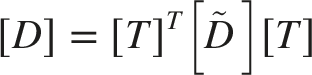
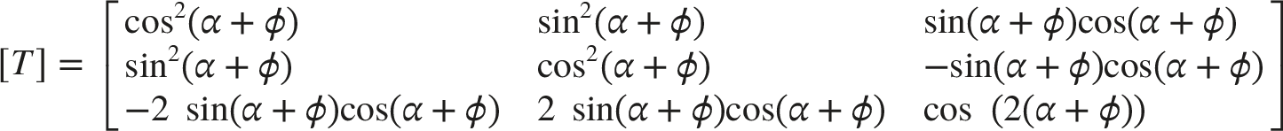
and its construction is discussed in section 2.2. An infinite repeating truss structure homogenizes the behavior of the discrete elements to a continuous one, which was used in the continuum model. Figure 1 illustrates this multiscale model, with mesoscale infinitely spanning truss structure embedded within macroscale linear elements. Deformation and geometrical changes of macroscale elements embedded within continuum shell elements and mesoscale hexagonal truss structure embedded within macroscale elements.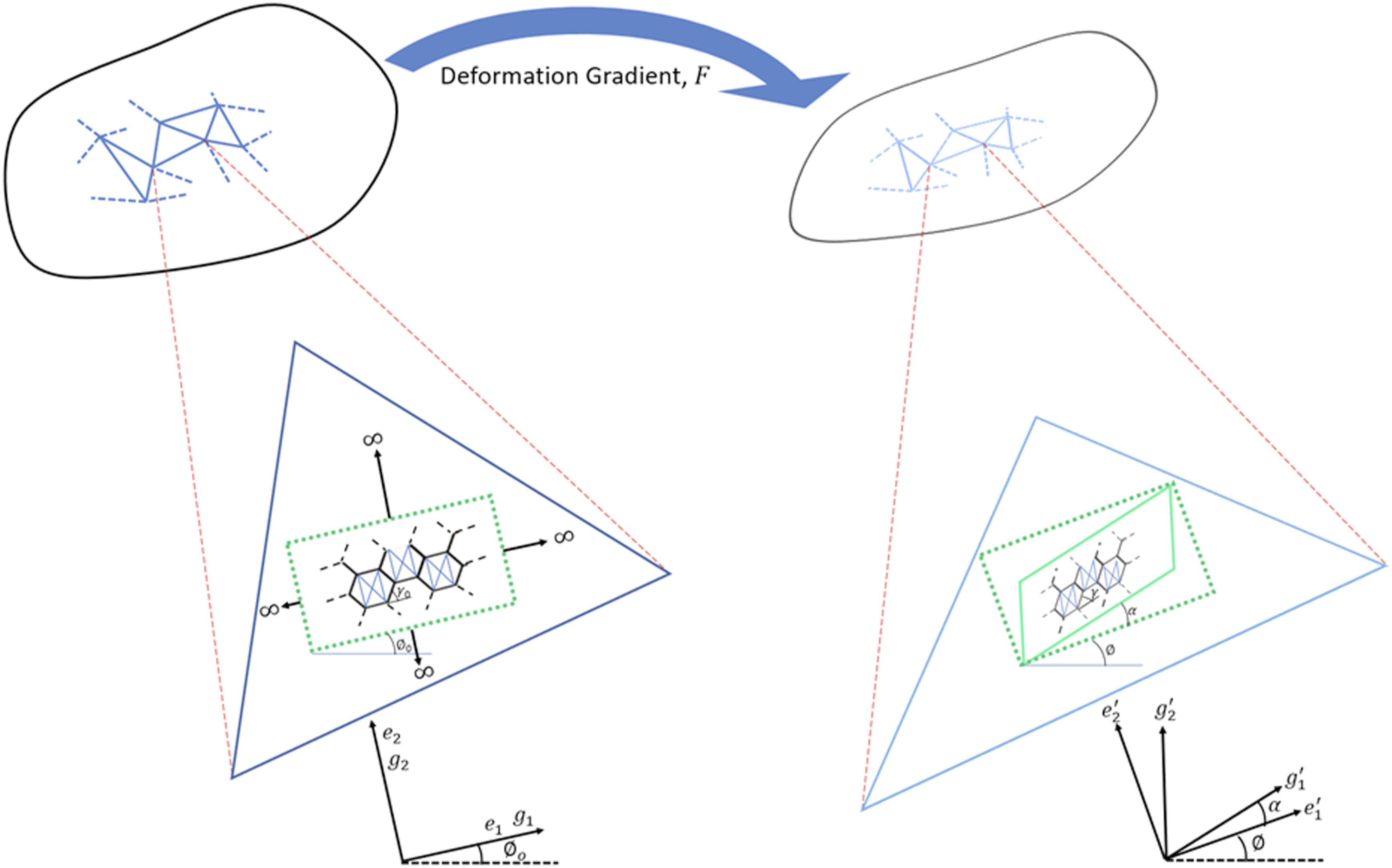
2.2. Truss model of jersey knit fabric
As described above, the truss model equates the loops of a jersey knit fabric to a hexagonal honeycomb structure (Figure 2(a)). Each truss is governed by a nonlinear constitutive relationship, the parameters of which were estimated from tensile testing. As will be discussed in section 2.4, the tensile test was carried out on the fabric sample with its principal direction at a certain angle with the load axis (in this case, 45o was chosen), named here as “weft angle”, and fitting the force-strain curve from the test to that obtained from the model simulating an identical virtual fabric sample. The fitting process involved iteratively tuning the parameters in the yarn force-strain equation. The yarns have zero stiffness in inter-truss pivoting, and as such, the trusses were considered to be one-dimensional. Inter-yarn interactions, namely friction, were characterized by a state-dependent coefficient of friction, also estimated through fitting the tests to simulation.
In our work, we included four additional trusses (dummy trusses) inside each hexagon, so as to prevent poor conditioning of stiffness matrix (Figure 2(a)). These additional trusses were given stiffness values several orders of magnitude smaller than that of the main trusses, hence minimizing the errors they may introduce. This approach helps a faster convergence of the model and also prevents singularity in a pure mesoscale construction of the model, where the entire fabric structure is represented by truss elements instead of linear continuum elements of the multiscale model. While the main thrust of this paper is the multiscale approach, addition of these extra trusses helps maintain uniformity across models. It may be noticed that only three additional trusses are needed to prevent stiffness matrix singularity; two vertical and one diagonal truss would have been sufficient. However, an additional mirror-symmetric diagonal truss was introduced to avoid asymmetry in deformation. Note that two of the trusses, where the yarns interlock, have a stiffness twice as that of other trusses, due to doubling of material. This is illustrated on Figure 2(a) with a double line. Finally, since yarns are generally compliant in compression (often leading to buckling), the stiffness of the trusses in compression was taken as two orders of magnitude less than in tension at any given strain. The actual value of stiffness of the trusses in compression was seen to not affect the simulation outcomes, as long as they were sufficiently smaller than the stiffness in tension. The course direction of the fabric is the direction in which the loops run, i.e. horizontal in Figure 2(a), whereas the wale direction is orthogonal to course. Figure 2(b) shows how a random and asymmetrical hexagon can be assembled infinitely in both directions. (a) Visualization of knit loops as a hexagonal honeycomb truss structure. Double lines illustrate doubling of yarns where yarns interlock. (b) Figure illustrates how a random and asymmetrical hexagon can be assembled infinitely.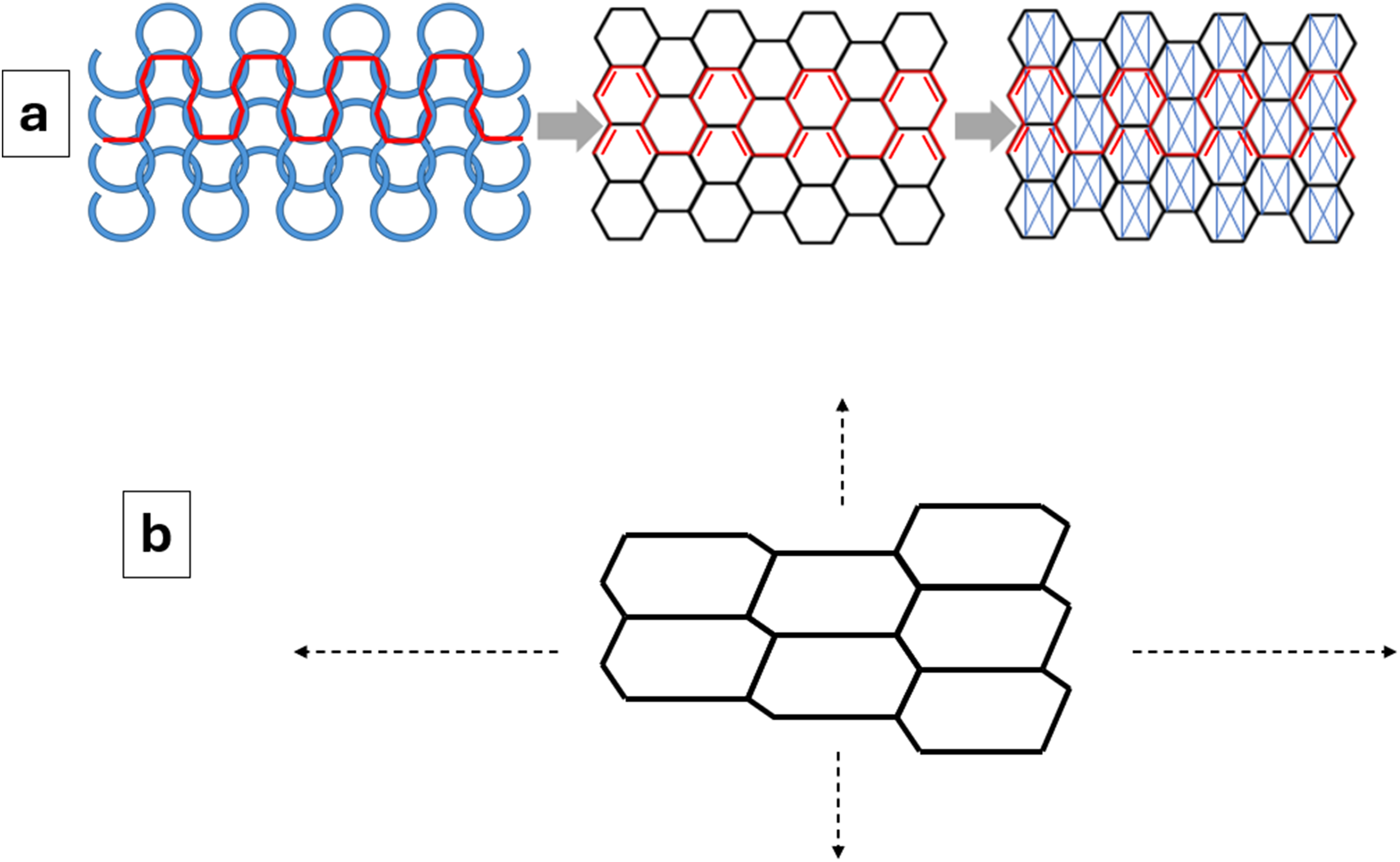
2.3. Computation of tangent modulus
As shown on Figure 1, on the macroscale, the course direction of the knit loops is oriented at an initial angle (weft angle)
The tangent modulus
The angles


In order to compute the tangent modulus of a triangular element of the fabric continuum in the local coordinate system

If
The deformations applied to the hexagon are shown in Figure 3. The displacement boundary conditions applied are as follows, where Boundary conditions imposed on a hexagonal unit cell at a given state of macroscale deformation, where nodal displacements are obtained from stretch tensor in the previous iteration of nonlinear solver. Node numbers shown in circles, and truss numbers shown in squares, arranged around the truss structure, as per the trusses they correspond to. “Dummy trusses” inside the hexagon are not labeled for clarity.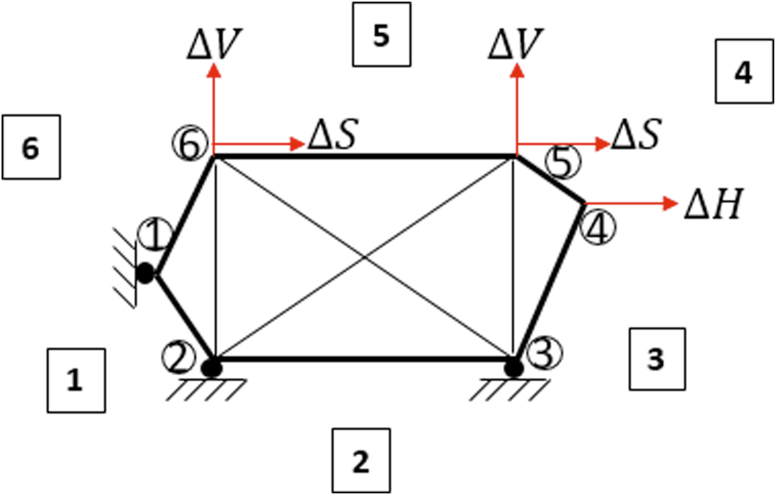


The truss numbers in Figure 3 are shown inside squares, where their arrangement around the truss structure corresponds to their truss. For the purpose of clarity, the additional “dummy trusses” inside the hexagon are not labeled. These trusses are numbered 7-10 in the computations. The roller points indicate that movement perpendicular to the boundary is restricted, but movement along the boundary is free.
In addition to the boundary conditions as described in Figure 3, the difference in
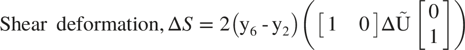
The model was further enhanced by incorporating friction between the fibers. Given that the trusses represent fibers and from Figure 2(a), it can be seen that interlocking loops of fibers can slip over one another, the trusses should also be able to do so in order to achieve a high-fidelity model. This was achieved with a novel approach, without needing to model relative movement between fibers, and maintaining the pin joints between the trusses. Solution of truss structure in every step of the homotopy method was first obtained on a truss structure without considering inter-fiber friction or slipping. The truss structure hence obtained was then modified to allow internal forces within the truss to impart inter-fiber slippage. Slip maintains the overall truss structure as it is, but relaxes the tension difference between trusses at points of slip by allowing fiber to flow across them. Allowing for slip in such a way essentially changes tensions in the trusses, but maintains their final lengths, which means that the initial length of the trusses will need to be modified, so as to satisfy the force balance equations. For example, if a truss carries a high tension, compared to another truss across the point of slip, the slip will cause the fiber to flow from the low-tension truss to the high-tension truss. Hence, the initial length of the high-tension truss will increase, while that for the low-tension truss would decrease. It should also be clarified that the “points of slip” as mentioned above are in fact trusses themselves. Referring to Figure 3, these trusses are truss numbers 4 and 6.
This approach is further illustrated in Figure 4(a), which shows the state of stretch in a given truss with the relative density of blue ticks. A more stretched (or tensioned) truss will have ticks separated by a greater degree, compared to truss under lower stretch (or lower tension). Figure 4(a) shows truss 1 as having a higher degree of tension compared to truss 5, which may lead to fiber flowing from truss 5 to truss 1 upon slip. Truss 1 then becomes more relaxed and truss 5 becomes more stretched, as illustrated with the tick spacing. The final lengths of each of the truss upon slip can be seen to be fixed. Given that, the new tensions in each of the trusses can only be true if their initial, unstretched lengths are adjusted accordingly. The following discussion formalizes this notion. (a) Illustration of fiber flow across a “point of slip”, with relative density of blue ticks representing the degree of stretch in each truss. Truss 1 relaxes and truss 5 stretches upon slip, as illustrated by the ticks. The final truss lengths are maintained through this slip process. (b) Angle 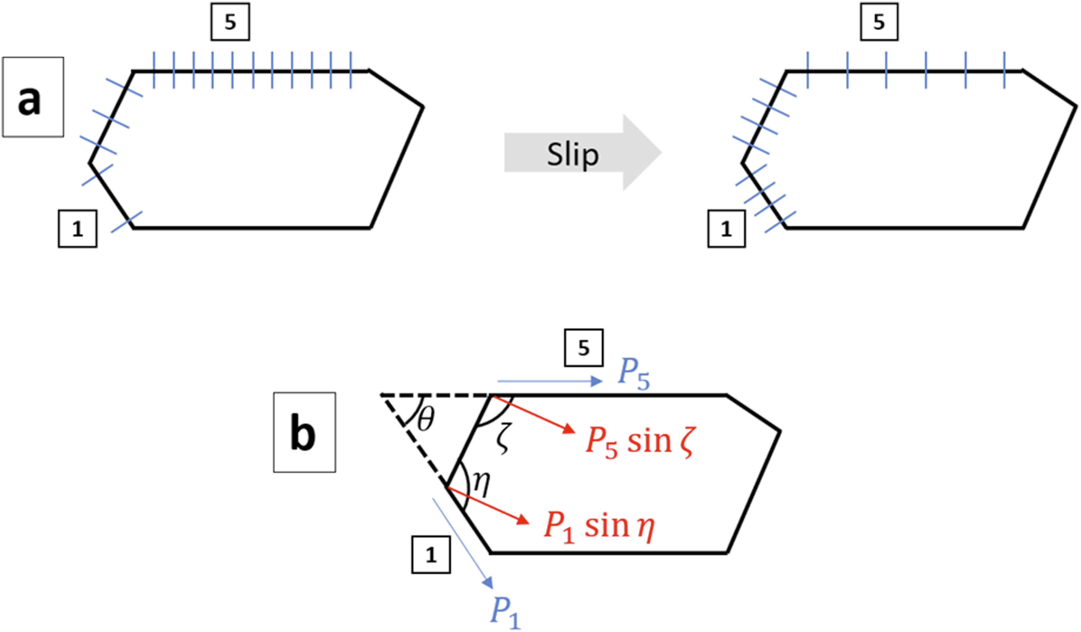
The degree of slip for a given state of deformation in the truss structure is a function of the coefficient of friction (which is an unknown quantity) and the parameters that relate the truss internal tension to its strain. The degree of slip will be driven by the difference in internal tensions between two nodes across a “point of slip”, which form a continuous fiber, and will be lessened by the degree of friction acting on the continuous fiber. This friction force is the product of a coefficient of friction and the normal force exerted on the point of slip from the two internal tensions. Let

The above equation can be understood as follows. The term
The new initial length of truss 1 is given by:
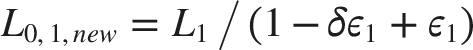
Similarly, the new initial length of truss 3 can also be estimated. The change in strain of truss 5 is the negative sum of the change in strains of trusses 1 and 3, which is the same for truss 2. The lengths of all other trusses remain the same, post slip.
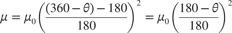
In our model, we introduced a dependency of coefficient friction on the wrap angle between trusses on either side of the point of slip. The intuition being that a higher degree of mutual wrap between yarns would lead to a higher degree of friction. Further, the coefficient of friction was defined as proportional to square of the wrap angle. This was chosen due to a linear increase in line segment of contact length between the yarns with wrap angle, and since the line of contact mutually increased between the two interlocking yarns, the area of contact is considered to be increasing as a square of the contact line segment length. Hence, the coefficient of friction increases quadratically with the wrap angle. If the angle between trusses 1 and 5 is
Now with the updated truss structure after slip, the next iteration in the nonlinear computation (using Newton homotopy method) is carried out. In practice, computation for convergence at the continuum scale was more time consuming if horizontal, vertical, and shear deformations were imposed simultaneously. It was observed to be more computationally efficient if the horizontal and vertical deformations were imposed first, the truss structure allowed to converge to a final state, and then shear was applied on this state and allowed to converge again. This final state was now used in further computations as described next.
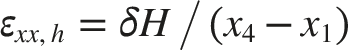
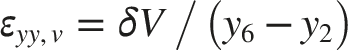
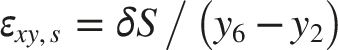
Once the final state of the truss is computed, the tangent modulus of the corresponding macroscale triangular mesh element was estimated by separately simulating stress response in horizontal, vertical, and shear directions. Small boundary node displacements ( Boundary conditions imposed individually on a hexagonal unit cell, corresponding to horizontal, vertical, and shear directions, each with small (∼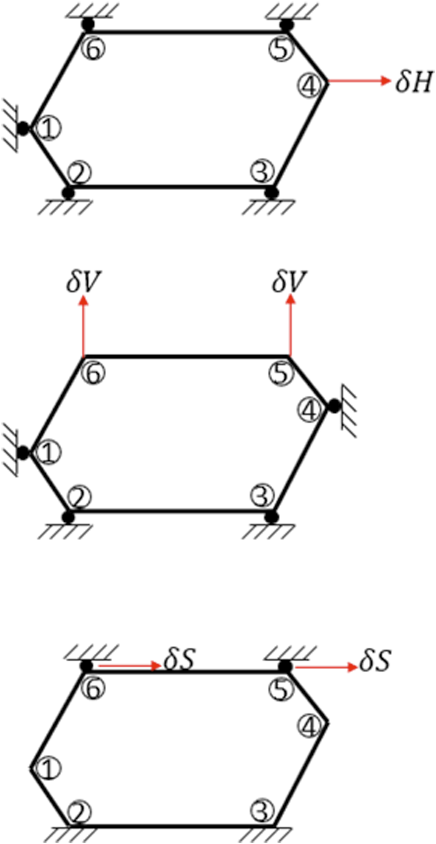
In the three deformation cases described above, the corresponding strains are:
Given a fabric thickness
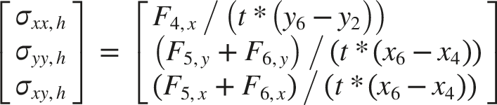
Stress tensors in vertical and shear cases can be computed similarly.
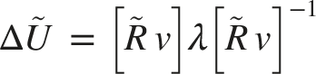
The strain and stress tensors computed in the three cases above were used in calculating the tangent modulus in the local reference frame
2.4. Constitutive equations of truss elements
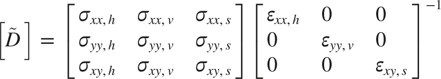
The above computations on the hexagonal truss structure require constitutive equations of each truss element. In the present study, the force-strain relationships of the trusses were given by a linear combination of three power terms, although other functions may also be used for better fit. The coefficient and powers in the equation for each truss, and the coefficient of friction at maximal wrap were determined by fitting a simulated force-strain curve of a virtual sample’s tensile test, to that obtained by actual tensile tests. Three samples were used in tensile tests and their force-strain curves were averaged. The tests and simulation stretched the fabric samples to 45% linear strain in the bias ( (a) Illustration of weft angle in a tensile test with oversized square sample clamped in a texture analyzer. (b) Picture showing the sample clamped in a texture analyzer prior to tensile test.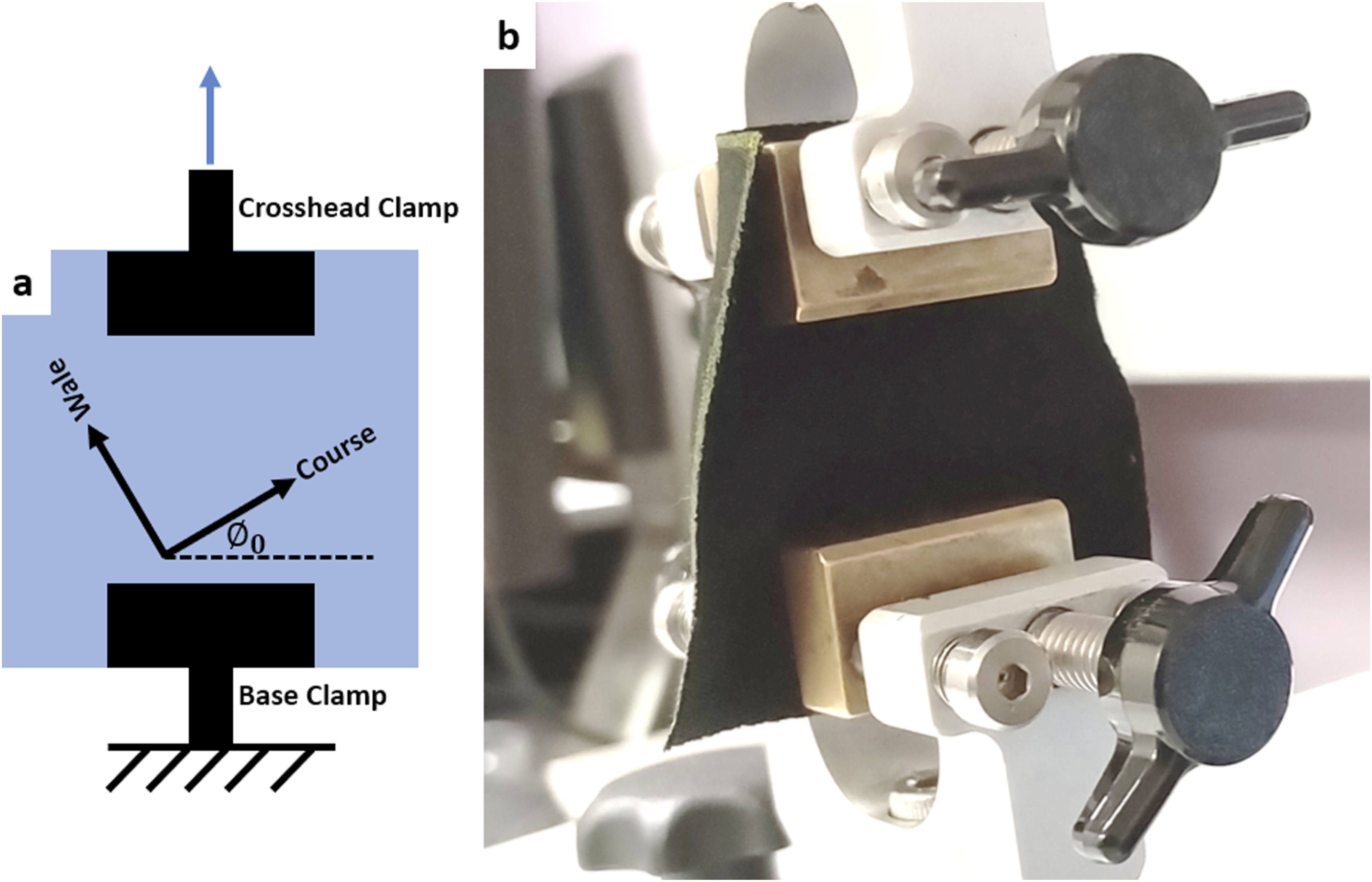
In all the simulations, including those carried out for validation as described in section 2.5, the overall fabric size and area of clamping were identical to the test cases. The triangular mesh elements under the clamped area were forced to be rigid. The triangular elements within the clamped area corresponding to the base clamp were held fixed, while the elements corresponding to the crosshead clamp area were moved rigidly, as per the crosshead displacement. The simulations used total Lagrangian formulation on the macroscale with 10 equal steps of the crosshead clamp displacement to achieve the total displacement. The convergence criteria within each step of the computation requires that the ratio of change of L2-norm of global nodal displacement vector in the given step to the L2-norm of cumulative global nodal displacement vector should be less than 0.1%. Finally, as mentioned earlier, for the convergence of the truss model within each element, Newton Continuing Homotopy method was used with 100 steps. This computational methodology was maintained for subsequent validation tests as well.
2.5. Validation of model
Upon estimation of truss constitutive equations, results from tensile test simulations of the model were compared to those from real tensile tests. Specifically, the force-strain curves were compared. The fabric samples were cut to squares of required dimensions, at different weft angles
In summary, we developed a finite element model of deformation of knit fabric using a multiscale approach. We used an infinitely repeating hexagonal honeycomb truss structure in the mesoscale to define the mechanical characteristics of triangular mesh elements on the macroscale. This was achieved through homogenizing the truss structure. The tangent modulus of the mesh elements in the macroscale was computed by simulating small deformations in the mesoscale truss structure embedded within it, and the truss structure in the mesoscale was in turn defined by deformation of the corresponding mesh elements in the macroscale. The mechanical characteristics of the truss elements were obtained by fitting a force-strain curve of the simulated tensile test on a virtual sample to that from real tensile tests, with stretch along the bias direction. Further simulations were carried out on virtual samples in several weft angles, and the results were compared to real tensile tests.
2.6. Geometrical measurements of unit cell
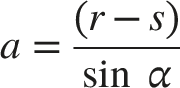
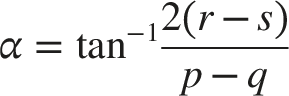
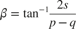
The thickness of the fabric stock was measured using a micrometer at different locations 5 times. The dimensions of the hexagonal truss structure before deformation were estimated optically using high resolution camera. Vertical and horizontal measurements of the hexagonal unit cell were first made, whose mean values were converted to relevant hexagonal parameters. Figure 7(a) shows the measured parameters and Figure 7(b) shows the relevant geometric parameters needed to fully define the unit cell. The relevant model parameters were calculated from measured parameters using following equations, derived using simple trigonometry. The parameters (a) Measured geometrical parameters of an undeformed and symmetric hexagonal unit cell. (b) Model geometric parameters in an undeformed hexagonal unit cell.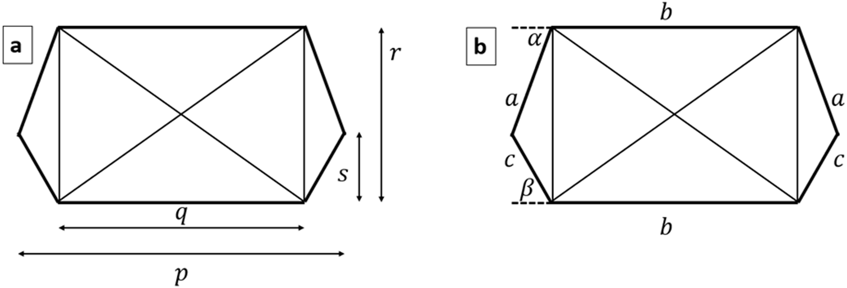

3. Results
3.1. Geometrical definition of initial hexagonal truss structure
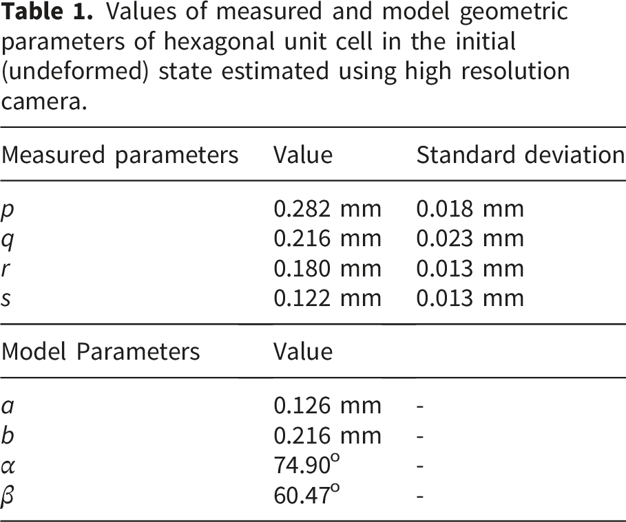
Values of measured and model geometric parameters of hexagonal unit cell in the initial (undeformed) state estimated using high resolution camera.
Referring to Figure 2 for equivalency between the hexagonal representation of stitches to actual fabric and to Figure 7 for dimensional parameters, the stitch length can be calculated as
3.2. Constitutive equations of trusses
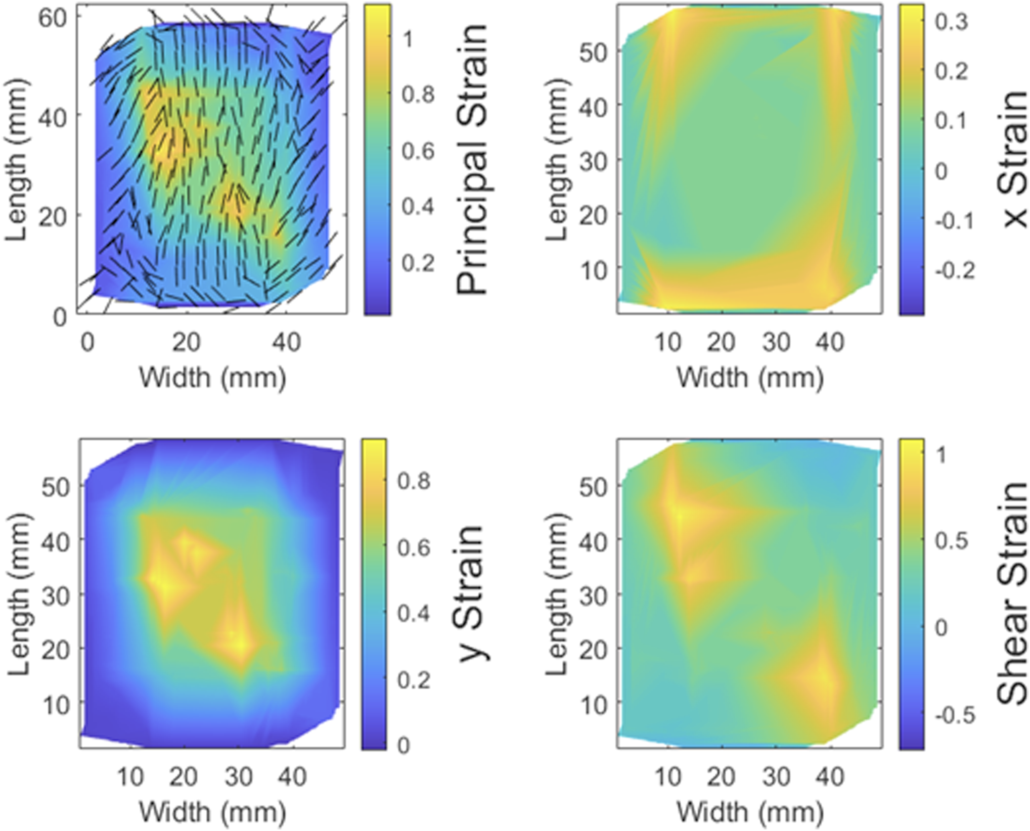
Tensile tests were carried out on fabric samples (n=3) in the bias direction. The coefficients and powers defining the force-strain relationship of trusses, as well as the coefficient of friction at maximal wrap used in the model were tuned so as to match the force-strain curve obtained from the tensile test simulation on the virtual fabric (also in the bias direction) to that obtained from averaging the real tensile test curves. The resulting curves are shown in Figure 8, with 90th percentile confidence interval of the tests shown as the shaded region. The root mean square error between the simulation and averaged tensile test results was found to be 0.0886 N, showing a good fit. Additionally, most of the model curve falls within the confidence bounds, showing a good agreement of the model to the physical behavior of the fabric. Figure 9 shows the corresponding 1st Principal Green-Lagrange strain, with their directions in black lines, strains in Force-strain curves of test (averaged from 3 samples) and simulation for stretch in the bias ( 1st Principal Green-Lagrange Strain, along with strain direction, 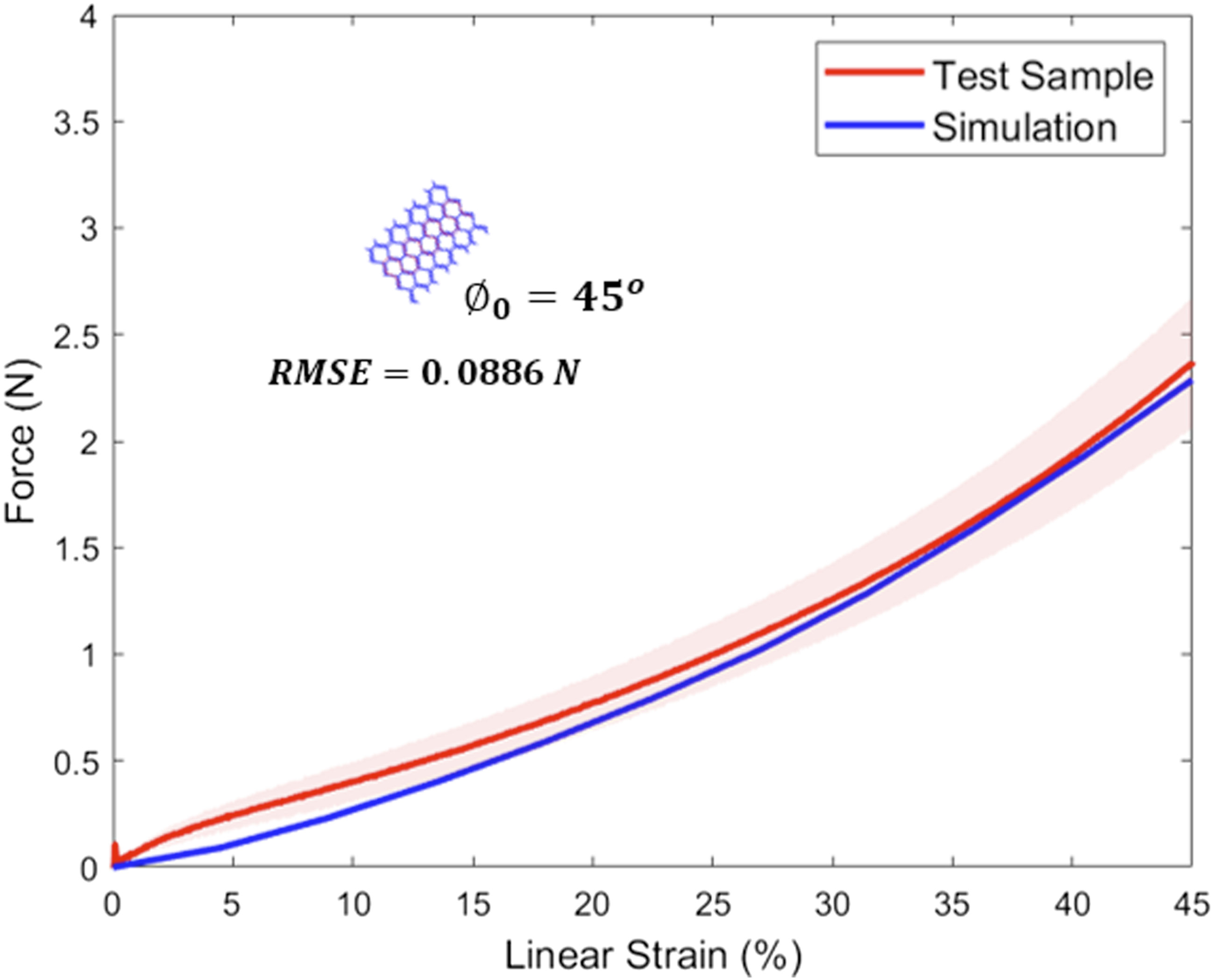
The following constitutive equations were obtained for trusses, with force and strain subscripts corresponding to the respective truss as shown in Figure 3. Please note that trusses 7-10 are not labeled in Figure 3 and represent the additional “dummy trusses” inside the hexagon. The intuition behind using the three terms in the equation is detailed in the Discussion section.


3.3. Validation of model
The constitutive equations were used to simulate the fabric tensile test up to 45% strain on virtual fabric samples with Force-strain curves of test (averaged from 3 samples) and simulation for stretch with weft angles of 0o, 20o, 30o, 60o, and 90o. 90th percentile confidence interval of the tests shown as the shaded region. Root mean square error (RMSE) between the simulation and averaged tensile test results also provided for each case.
4. Discussion
We constructed a finite element model of a generic jersey knit fabric using the hexagonal truss structure approach developed by Araujo. 10 Our construction of this truss structure and its embedding within a macroscale continuum are shown in Figures 1 and 2. We described the construction of the unit truss structure along with boundary conditions imposed on its deformation translated from macroscale elements (Figure 3), the normal forces at the point of slip (Figure 4), and small nodal displacements imposed on the deformed truss structure to compute the tangent modulus on macroscale (Figure 5). We discussed how tensile tests were used in determining the truss constitutive equations, with the same test setup used in validation tests (Figure 6).
Table 1 shows the geometric parameters of the hexagonal unit cell obtained from optical data, with the parameters illustrated in Figure 7. Upon obtaining the parameters of truss constitutive equations from fitting bias tensile test data to corresponding simulation (Figures 8 and 9), we sought to validate the model with tensile tests along several arbitrary weft angles ranging from 0o to 90o (Figure 10). Figure 10 shows that good agreement is obtained between the simulation and tests at different weft angles, as quantified by RMSE, hence providing a high degree of validation for the multiscale model. In general, the fit is better at weft angle lower than 45o compared to the fits at weft angles higher than 45o. This could be because the truss constitutive equations did not fully capture the real yarn behavior, and it is possible that more terms in the equations would allow for better fits throughout the range of weft angles. It was expected that the fits would be better at weft angles closer to 45o, since the truss force-strain parameters were optimized for the bias tensile test. However, we see that while the fit is poorer at 90o compared to 60o weft angles, there is no correlation between weft angle and fit, at weft angles less than 45o. The latter result is encouraging as it shows that the model behavior remains consistent at different orientations less than 45o, similar to a real fabric behavior. The model overall can obviously be improved with better fit and more terms in the constitutive equations.
The overall sample stiffness (total force divided by total deformation of the fabric sample) of the model also shows good correlation to the tests. Except for a weft angle of 20o, the real tests show a general decrease in overall stiffness with increase in weft angle, which is replicated by the model (which does not show an increase at 20o weft angle), further strengthening the viability of the model. This is shown in Figures 8 and 10. As the weft angle increases, the component of stretch along the course direction increases; with knit fabric generally being more compliant in course-wise stretch compared to wale-wise stretch, a decrease in stiffness is seen. 3 A stiffening effect caused by locking of the knit loops with increasing stretch is also seen in the curves, which is also captured well by the model.
The constitutive equations for trusses were constructed with three terms. The first term has an exponent to the strain that is greater than 1 (2.5), the second term is linear, and the third has the exponent to strain that is less than 1 (0.8). Due to their distinct characteristics, these exponent types were specifically chosen so as to allow for tuning specific characteristics in the fabric sample force-strain response and enable fitting the model to the experimental data. The first term imparts a rapid increase in force with increasing strain, particularly at larger strain values. The second term exhibits constant stiffness, allowing for a constancy throughout the deformation. The final term imparts a fast rise in force at smaller strains, which levels off at larger strains. By tuning the coefficient of each, we can tune the overall fabric sample force-strain characteristics to enable fitting. In essence, we are exploring the relative dominance of each type of behavior of the trusses-if the truss stiffens at higher strains, if its stiffness is highest at lower strains, or if it tends to remain constant. This intuition does not account for geometric stiffness; however, it allows us to probe for yarn behavior.
The model described here is expected to be agnostic to the fabrication process, yarn material and knit geometry. This is because the behavior of a fabric under deformation with a given set of fabric properties will be captured in the constitutive equations obtained by a single tensile test. In this work, we purchased fabric stock from a general purpose fabric store, without controlling for the fabric properties. The deformation response property of this general fabric could be captured in the constitutive equations, which lent themselves to a close agreement between simulation and tensile tests along several weft angles. This demonstrates the power of this model, which allows for capturing the required mechanical properties of any given fabric and produce predictions of their response to arbitrary deformations.
The model developed here, while simulated and tested with fabric subjected to loading only along specific axes, is applicable for any knit fabric construction, with varying knit geometries, yarn materials, wale and course directions, and loading directions within the same continuous fabric. Such a general fabric sample may be divided into homogenous areas with constant yarn and knit properties and a unique loading direction. These areas can be stitched together into a larger finite element model. This model construction could find applications in performance garments and composite material forming, among others.
One of the possible limitations we predicted during the conception of this multiscale model is that a model using trusses as discrete elements representing loops of complex geometry may not be as accurate as concurrent multiscale models that use higher fidelity geometric models, such as those used by Fillep and Dinh.18,19 However, our model shows closeness of fabric behavior between simulation and test, similar to that obtained from those higher fidelity models, and due to the use of simple, albeit nonlinear trusses, the computation results in a high degree of efficiency. Additionally, our model covers a wider range of sample deformation parameters such as weft angles than those models. Simulating a 2″ x 2″ (50.8mm x 50.8mm) sample with 169 nodes and a structured mesh consisting of 288 triangular elements took an average of 3.5 minutes on a general-purpose personal laptop with 8GB random access memory and Intel Core i5 processor with speed of 1.19GHz. Furthermore, our model does not assume orthotropicity of the fabric, that many of the sequential multiscale models do, such as those detailed by Weeger, Abghary, Hessami and Do.20–22,25 Moreover, the model discussed here captured the frictional forces and yarn slippage, which is absent in all macroscale models to our knowledge. Finally, our model requires only one tensile test in the bias direction in order to estimate all relevant material parameters to be used, simplifying the overall process, compared to approaches that require tensile tests in various axes, for example as described in the work by Wang. 24
Future work involves achieving a better fit between simulation and test in the bias direction that sets the parameters for the model. This can be done by increasing the number of terms in the equation describing the truss constitutive relationship. Genetic algorithm or built-in MATLAB optimization tools such as fmincon will be used in the future that would also enable achieving a faster and closer fit to the bias test, particularly if more free parameters and more terms in the equation are used. The parameters obtained in this paper have been done so by trial-and-error, which may be set as initial values in the genetic algorithm or in other optimization algorithms, if similar equations are used. A better fit in the bias direction will result in more accurate fabric behavior in deformation along other arbitrary axes. We noted the poorer fit at 90o weft angle simulation compared to other cases, as well as a general underestimation by the model of stiffness at low strains across all weft angle cases. The confidence interval bounds in Figure 10, particularly in case for weft angles of 0o, 20o, and 90o are narrow and the model lines fall outside of these bounds, suggesting that the model discrepancy is likely based on model parameters rather than variability in test results. We also note that a limitation of the current model is that it was compared to tests with overall tensile strains up to 45%. We believe that a richer definition of truss force-strain relationship through additional terms, with “more knobs to turn”, will improve the fit across all weft angles, as well as for wider ranges of overall strains. Additionally, future work will include a larger sample size so that the confidence bounds are tightened across all cases. Another limitation of this model is that it does not simulate wrinkling, which can be regarded as local buckling. 1 Future work will also incorporate buckling effects by taking into account fabric bending behavior, and allow for simulation of wrinkle geometry, such as height and width of wrinkles. This model will also be extended to other types of knits such as interlock and warp knits. The truss structure approach will be extended to these fabrics and will be validated in a similar way as described in this paper. Finally, we aim to compare the strain distribution pattern obtained from simulation, such as that shown in Figure 9, to surface strain deformation for fabric samples using Digital Image Correlation (DIC) techniques. We expect DIC tests would further strengthen the viability of our model.
5. Conclusion
This paper describes a novel multiscale numerical model for predicting deformation of jersey knit fabrics. This model solves the mesoscale truss structure concurrently with the macroscale continuum surface of the fabric and does not assume orthotropicity or heterogeneity. In this model, the tangent modulus of the continuum elements was informed by simulating small deformations on a single unit of the truss structure. The model was further enhanced and increased in fidelity by implementing slip between fibers in a novel way. Generally, FEA models simulating complex geometry face a tradeoff between being faithful to actual geometry (enabling higher accuracy) and computational efficiency. The multiscale model discussed here bridges that gap by minimizing nodes in the system and increasing fidelity of inter-fiber interactions. This general model is computationally efficient compared to other concurrent models. The model was validated against tensile tests in various weft angles, and good agreement was noted. The ease of implementing this model is exemplified by the fact that only one tensile test is needed to define the fabric material parameters needed and its implementation in programming environments such as MATLAB and Python is simple. Future work will seek to further improve the fidelity of the model and obtain better fit to physical tests, extend the model to other knit fabric types, and to compare strain distribution in simulations against real tests using DIC. This model has applications in athletic wear, composite fabrication, and medical garments.
Footnotes
Acknowledgements
The authors would like to thank Prof. Gregory Rutledge, Massachusetts Institute of Technology and Prof. Bradley Holschuh, University of Minnesota for their technical advice on this work.
Ethical considerations
This article does not contain any studies with human or animal participants and informed consent is not required.
Author contributions
Funding
The authors disclosed receipt of the following financial support for the research, authorship, and/or publication of this article: Dr. Akshay Kothakonda was supported by the MathWorks Fellowship. MathWorks Inc. was not involved in the research.
Declaration of conflicting interests
The authors declared no potential conflicts of interest with respect to the research, authorship, and/or publication of this article.
Data Availability Statement
Data will be made available upon reasonable request.