
Abstract
Kinematic reliability is an important evaluation index for measuring the dynamic kinematic accuracy of mechanisms, which can more essentially reflect the kinematic performance of the mechanisms. Based on the traditional theory of mechanism kinematic reliability design, this study conducts an in-depth exploration of the kinematic accuracy of a special machine tool for variable hyperbolic circular-arc-tooth-trace (VH-CATT) cylindrical gears. To address the principle errors and low processing accuracy in machining VH-CATT cylindrical gears, this research innovatively applies advanced reliability assessment methodologies to this specific machine tool, providing a novel theoretical reference for its precision design. By considering drive error as the key factor, systematic error analysis of the machine tool was conducted. An error calculation model for the machine tool was established using homogeneous coordinate transformation and multi-body system theory. The advanced first-order second-moment (AFOSM) was adopted to accurately calculate the kinematic reliability of the machine tool in the x, y, and z directions, as well as the combined direction and reliability sensitivity. To ensure the accuracy of the calculation results, the Monte Carlo method was further used for verification. The results indicated that the values obtained by the two methods were highly consistent, fully validating the effectiveness and applicability of the AFOSM in calculating the kinematic reliability and reliability sensitivity of this machine tool. This research provided a novel theoretical framework for the kinematic accuracy reliability analysis of dedicated machine tools, offering significant insights for precision design and error compensation.
Introduction
With the growing demand for higher processing accuracy in CNC machine tools, increasing attention has been focussed on enhancing the precision, reliability, and stability of these systems. The production quality of products was directly determined by the processing accuracy of CNC machine tools. 1 Kinematic accuracy is an important influencing factor for the processing accuracy of machine tools. 2 The kinematic accuracy reliability analysis is an effective means to improve the processing quality and service life of machine tools.
In recent years, the reliability research on the precision of CNC machine tools has received extensive widespread attention. For example, Chen et al. 3 established the accuracy stability model of machine tools and proposed a machining accuracy reliability evaluation method based on the quasi-Monte Carlo simulation. Zhang et al. 4 developed a machining accuracy reliability model and obtained the reliability of machining accuracy during the peripheral milling process of thin-walled components. Fan et al. 5 proposed a novel global sensitivity analysis method for vital geometric error based on multi-body theory and truncated Fourier expansion. Zhao et al. 6 proposed a fast algorithm for evaluating the kinematic reliability of planar parallel manipulators based on the error propagation theory of planar motion groups and the truncated Gaussian distribution and verified its effectiveness through comparison with Monte Carlo simulation results. Niu et al. 7 established a machining accuracy reliability analysis model for machine tools using the advanced first-order second moment method. Through statistical analysis of geometric errors and their corresponding tolerances, reliability sensitivity quantification driven by tolerances and total manufacturing cost modelling were investigated. Liu et al. 8 took the motion accuracy of space deployable mechanisms during the deployment process as the research object, proposed an adaptive hybrid surrogate model reliability evaluation method based on an improved weight measurement approach and verified the accuracy of the hybrid surrogate model method by the Monte Carlo method. Yang et al. 9 proposed an APCK-TBS method that integrates the Adaptive Polynomial-Chaos-based Kriging (APCK) surrogate model with the Truncated β-sphere Sampling (TBS) approach, enabling accurate and efficient analysis of the time-dependent reliability of landing gear retraction mechanisms. Shen et al. 10 proposed a new reliability analysis framework for robotic motion systems that integrates the moment-based method with a Bayesian inference-guided probabilistic model updating strategy. The effectiveness of the proposed framework was validated through comparison with Monte Carlo simulation and other mainstream methods.
The aforementioned research focuses on the reliability analysis of mechanism kinematic accuracy and systematically proposes multiple innovative methods. These methods significantly improve computational efficiency while ensuring accuracy, providing effective tools for the reliability design and assessment of complex electromechanical systems. Since the structural design of the special machine tools for VH-CATT cylindrical gears is still in its infancy, their processing accuracy and service life need to be improved. Therefore, in order to enhance high precision and high reliability of products, research on the modelling and analysis of kinematic accuracy reliability of a special machine tool for VH-CATT cylindrical gears has important engineering practical significance. The kinematic accuracy of machine tools often involves complex nonlinear error propagation. The Advanced First-Order Second-Moment (AFOSM) method effectively addresses engineering nonlinear problems by handling implicit equations through gradient calculations. By computing the reliability index β, AFOSM can intuitively quantify the failure probability of machine tools under specific working conditions and identify key sensitive parameters, providing a basis for precision design and compensation. This article took the special machine tool for VH-CATT cylindrical gears as the research object, established an error model through homogeneous coordinate transformation and multibody system theory. On this basis, the kinematic accuracy reliability of the machine tool was calculated using the advanced first-order second-moment method and Monte Carlo method. The flowchart of the research methodology in this research is presented as follows (Figure 1).

Flowchart of the research methodology.
Special machine tool of VH-CATT cylindrical gear
VH-CATT cylindrical gear is a new type of gear with a special form of circular-arc-tooth-trace cylindrical gear. Its tooth trace is a spatial circular arc in the tooth width direction, with the tooth profile in the middle section being an involute, and the remaining cross-sections being envelopes of uniformly varying hyperbolic families. As shown in Figure 2, 1 is the end face of gear; 2 is the end face tooth profile, and it is a non-involute tooth profile; 3 is the middle section tooth profile, and only the middle section tooth profile in the gear is an involute; 4 is the circular arc tooth profile. Its radius is obtained through optimised design.
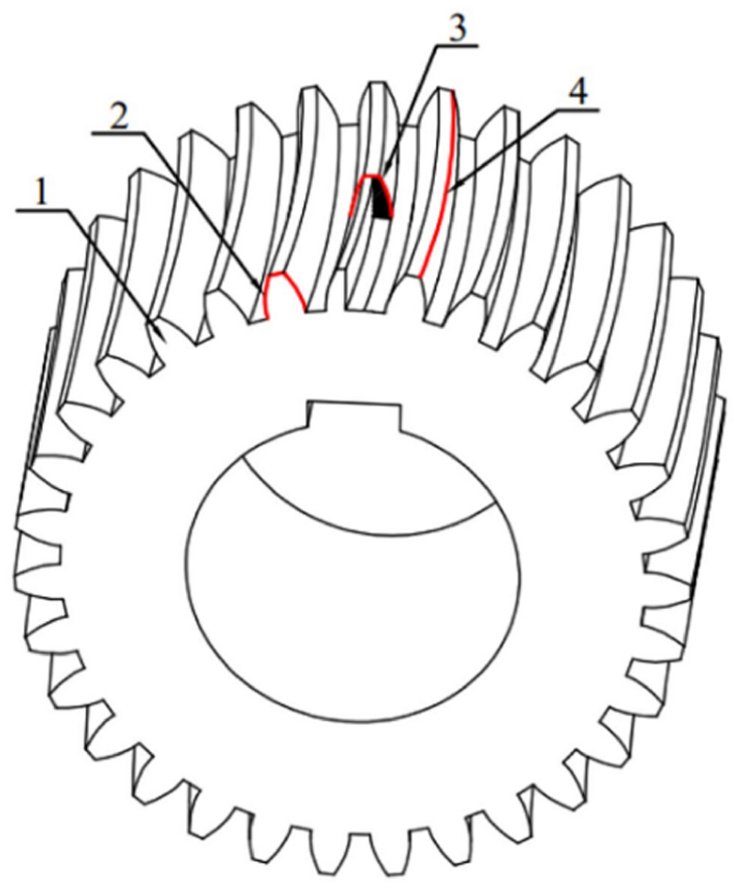
Structure of VH-CATT cylindrical gear.
This innovative transmission system presents significant benefits, such as optimal meshing performance, a substantial coincidence coefficient, robust load-bearing capabilities, and high transmission efficiency. Furthermore, it operates with exceptional stability and minimal noise, eliminating the need for additional axial forces.11,12
Using the rotating cutter disc, VH-CATT cylindrical gears are manufactured with high precision. This process relies on a meticulously controlled generating motion between the gear blank and its corresponding customised cutting tools. 13 The processing principle of this gear is shown in Figure 3.
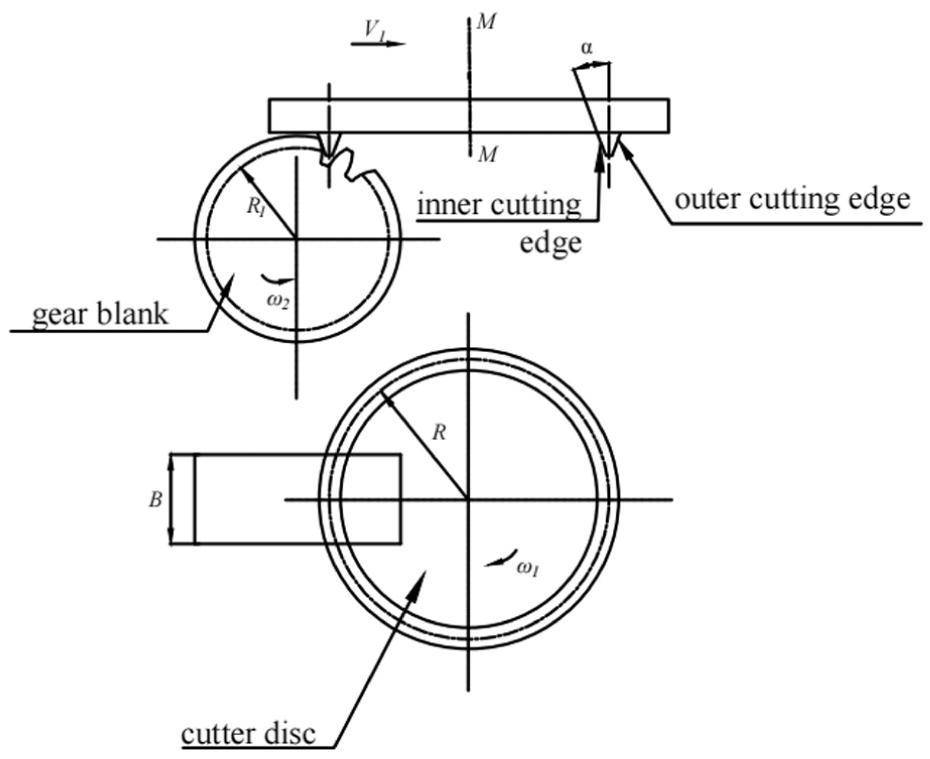
Processing principle of VH-CATT cylindrical gear.
In Figure 3, α represents the angle between the inner and outer edges of the cutter and the axis; B is the width of the gear blank; R is the radius of the cutter disc. M-M is the rotation axis of the cutter disc. When processing the gear, the gear blank rotates counterclockwise with an angular velocity of ω2 and simultaneously moves horizontally at a speed of V1 relative to the cutter disc, while the cutter disc rotates clockwise at an angular velocity of ω1 around the spindle. After processing a pair of tooth surfaces and indexing, the next pair of tooth surfaces continues to be processed.14,15 At the same time, to ensure that the middle section of the gear has an involute tooth profile, the relationship between ω2 and V1 is shown in equation (1):

where R1 is the pitch circle radius of the gear; ω2 is the rotational angular velocity of the gear blank.
The processing of this new gear transmission on high-end CNC machine tools is characteristically an approximate method. This approximation stems from its primary reliance on interpolation for machining compensation, which inevitably gives rise to principle errors. The machining error is relatively large on ordinary machine tools, and the process of machine tool adjustment is complex and difficult to promote. The newly developed special machine tool for VH-CATT gears is designed based on meshing principles with corresponding mathematical modelling and derivation, using corresponding spatial relationships to effectively avoid such principle errors. The successfully developed first VH-CATT gear special machine tool is shown in Figure 4.
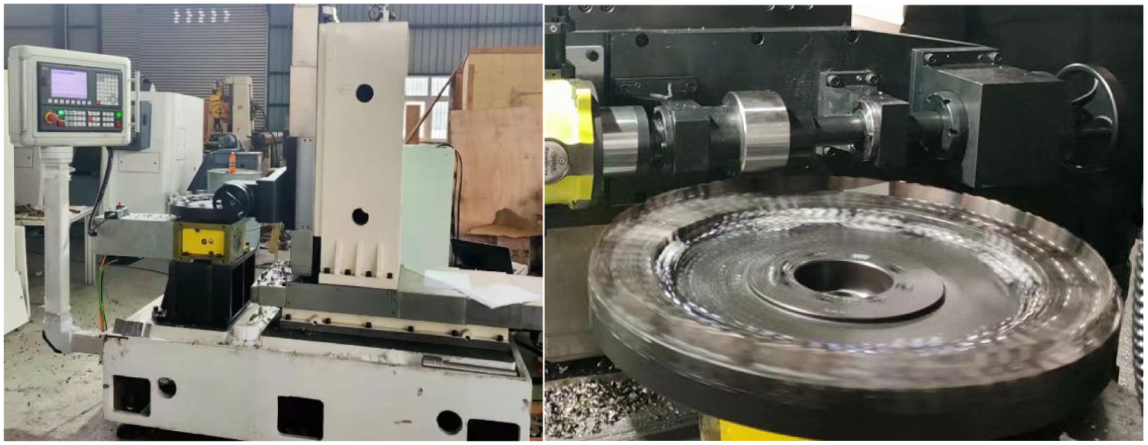
First prototype of the special machine tool for VH-CATT cylindrical gear.
Kinematic error analysis of a special machine tool for VH-CATT cylindrical gears
The fundamental task of kinematic analysis for mechanical systems involves elucidating the kinematic interrelationships among their constituent elements, while deliberately abstracting from the force and torque dynamics that govern their motion generation. 16 Kinematic error analysis of mechanisms is the premise and foundation for reliability analysis of mechanisms. There is a certain error between the kinematic law of the output component of the mechanism and the ideal kinematic law. This error is the kinematic error of the mechanism. 17 Therefore, establishing an accurate, true, and reliable spatial error model is the premise and key to optimising the spatial kinematic accuracy of the machine tools.
Taking the special machine tool for VH-CATT cylindrical gears as the research object, this machine tool mainly has eight components, with names and corresponding numbers (0–7) as shown in Figure 5. The machine tool’s X, Y, and Z coordinate feed is realised by integrating X, Y, and Z-direction guide rails with their respective sliding plates, thereby providing controlled linear motion along these axes. The X-axis screw and guide rail of the machine tool are directly installed on the body, driving the upright column to move left and right along the X-axis; the Z-axis screw and guide rail are directly installed on the upright column, with the Z-direction slide moving forward and backward along the Z-axis on the upright column; the Y-axis screw and guide rail are installed on the Z-direction slide, with the Y-direction slide moving up and down along the Y-axis on the Z-direction slide; the rotating axis B is installed on the spindle, with its axis parallel to the Y-axis; it drives the cutter disc to rotate around the spindle, with the cutter installed on the large cutter disc rotating with the cutter disc; the rotating axis C is installed on the Y-direction slide, with its axis parallel to the Z-axis, driving the gear blank to rotate around the Z-axis. The gear blank rotates around its own axis and simultaneously moves horizontally towards the cutter disc to realise the generative processing of VH-CATT cylindrical gears.
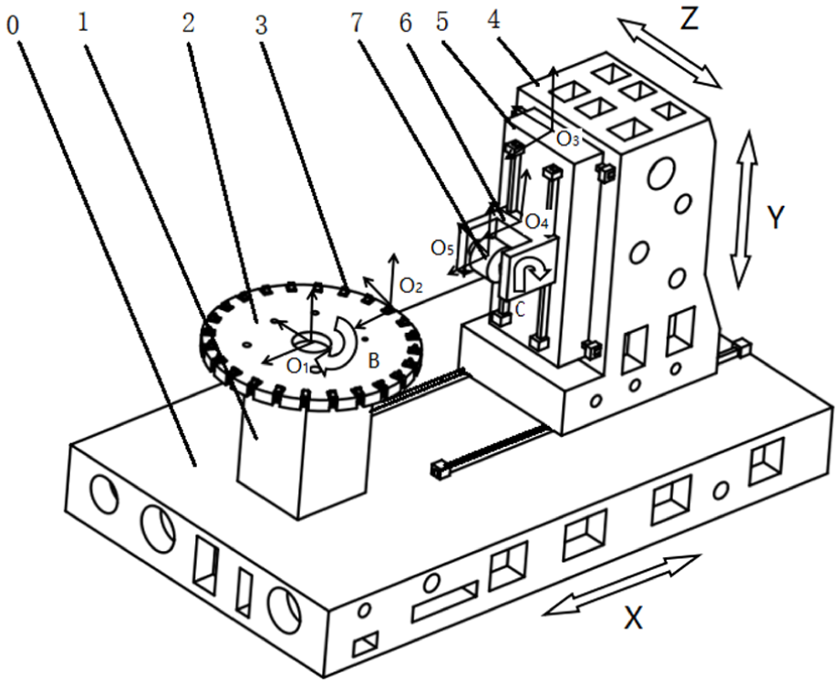
Structural schematic diagram of the special machine tool for VH-CATT cylindrical gear.
For analytical purposes, the machine tool is modelled as a multi-body system, with its abstraction guided by its physical realisation and the scope of the investigation. Firstly, coordinate systems were set up, and a right-handed rectangular Cartesian coordinate system was used to name the coordinate systems of the machine tool, with each coordinate axis of the coordinate system parallel to the main guide rails of the machine tool. As shown in Figure 4, the coordinate origins of the body, spindle box, and large cutter disc were all set at the centre of the large cutter disc O1. The cutter consisted of inner and outer cutters, with the coordinate origin of the cutter coordinate system set at the centreline of the installation positions of the inner and outer cutters O2. The coordinate origins of the upright column and Z-direction slide coordinate systems were set at the centre of the top of the Z-direction slide O3. The coordinate origin of the Y-direction slide coordinate system is set at the centre of its upper end face O4. The coordinate origin of the gear blank coordinate system is set at the centre of the gear blank O5. Among them, the coordinate system at location O2 is translated by a vector
The fundamental structural characteristics of the machine tool were analysed, culminating in the derivation and establishment of its topological structure diagram. As shown in Figure 6, with 0–3 representing the cutter path and 0–4–7 representing the workpiece path.

Topological structure diagram of the machine tool.
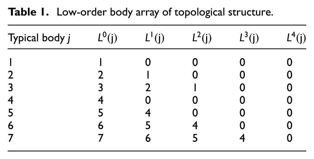
The low-order body array is a mathematical representation of this topological structure, where each number represents a component, and its position in the array reflects its hierarchical relationship within the kinematic chain, that is, which component is its direct or indirect “parent” component. This mapping is strictly based on the actual physical connections and degrees of freedom of the machine tool, laying the foundation for subsequent kinematic error analysis and reliability calculations. For example: Body 0 (body): As the foundation of the entire machine tool, it is usually considered stationary and serves as the starting point for all kinematic chains. Body 1 (spindle box) is directly connected to the body (0), so its L0(1) is 1. There is no further parent body above, then L1(1) is 0. Body 2 (large cutter disc) is mounted on the spindle box (1) and driven by rotation axis B, so its L0(2) is 1. There is still a parent body above it. So the L1(2) is 1. And so on.
The low-order body array table as shown in Table 1.
Low-order body array of topological structure.
Based on the topological structure diagram of the machine tool and the relationship between adjacent low-order bodies, the characteristic matrix between two bodies under error conditions can be derived.18,19
When there was only axial translation along the X, Y, and Z axes and no rotation between two coordinates, the coordinate transformation matrix between any two coordinates was defined by equation (2):
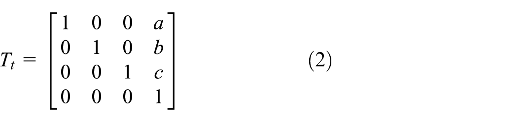
In the above equation, a,b,c represents the translation along the XYZ axes respectively.
When only rotational transformations about the X, Y, and Z axes existed between two coordinate systems, without any axial translation along these axes, the coordinate transformation matrix was defined by equation (3):

In the above equation, α, β, γ represents the rotation angles around the XYZ axes respectively.
When there were both axial translation along the X, Y, Z axes and rotation around these axes between two coordinates, the coordinate transformation matrix between any two coordinates was defined by equation (4):

The driving error of the mechanism’s power source refers to the output error of driving components (such as motors). If the motor fails to drive the moving parts to the theoretical position at the specified time point, it will inevitably lead to deviation of the mechanism’s kinematic output from the theoretical value, thereby affecting the kinematic reliability of the mechanism.
For the kinematic error analysis of the VH-CATT machine tool, this paper only considers the error caused by driving forces, and other types of errors are temporarily ignored. Below is the modelling of driving errors.
Assuming the homogeneous coordinate of the forming point
The homogeneous coordinate of the point

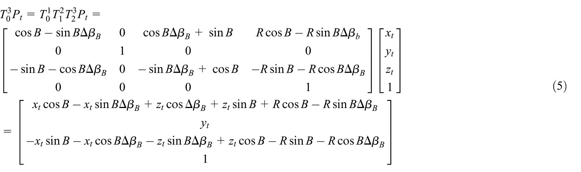
Ideally, using homogeneous transformation along the cutter-body and workpiece-body routes, respectively, both were transformed into the global coordinate system, and the obtained global coordinates should be equal.20,21
In practice, due to various error factors, the actual forming motion is an imprecise process. The motion error coupling among the machine tool’s bodies is analysed using multibody system theory. Considering only drive errors, the spatial error model of the machine tool is obtained by equation (7):

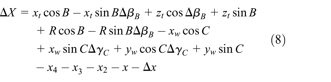
Thus, the error model of the tool point on the three coordinate axes was defined by equations (8)–(10):

The total positional error of the machine tool was defined by equation (11):

Kinematic accuracy reliability analysis of a special machine tool for VH-CATT cylindrical gears
The proper operational capability of a mechanism is critically assessed by its kinematic accuracy, which stands as a pivotal performance indicator. 22 To enable a mechanism to work properly, its output kinematic error must meet the requirements of the mechanism’s kinematic accuracy, that is,

where
Given that each initial error is a random variable with statistical characteristics rather than a deterministic value, the kinematic error output by the mechanism’s follower is consequently also a random variable. Obviously, technicians are more concerned about its kinematic reliability. 23 The reliability of kinematic accuracy of a mechanism can be defined as, under specified conditions, within the specified operating range or at the specified operating position, the probability that its output motion error remains within the allowable range is

where
In contemporary engineering, the trajectory of mechanical system development is marked by an emphasis on lightweight construction, high operational speeds, enhanced flexibility, and superior precision. This developmental paradigm, however, introduces more formidable challenges in ensuring the requisite high reliability of such mechanisms. Therefore, the research on the reliability of mechanism kinematic accuracy has important theoretical and practical significance.
Introduction of advanced first-order second-moment method (AFOSM) and Monte Carlo method
When the performance function is nonlinear, the AFOSM is a commonly used and relatively accurate reliability calculation method. 24 The reliability calculated by the AFOSM is verified for correctness by using the Monte Carlo method.
Assuming that the most likely failure point in the failure domain is

Since the most likely failure point

After rearranging, it is obtained that

The reliability index


The basic idea of the Monte Carlo method for solving the failure probability
The exact expression for the failure probability is the integral of the joint probability density function of the basic variables over the failure domain, which can be rewritten as the mathematical expectation form of the failure domain indicator function
where
From the above equation, it can be seen that the failure probability is the mathematical expectation of the failure indicator function. According to the law of large numbers, the sample mean of the failure domain indicator function is used to approximate the mathematical expectation of the failure indicator function. This can be interpreted as follows: the ratio of the number of samples

Kinematic accuracy reliability calculation
When the input errors are mutually independent and all conform to a normal distribution (i.e.,
The performance parameters of the special machine tool for VH-CATT cylindrical gears are shown in Table 2. The inherent error distribution pattern and statistical descriptors of parameters were obtained through performance parameters of the machine tool— (Table 2) and equations (8)– (10)—as shown in Table 3.
The performance parameters of VH-CATT cylindrical gear machine tool.
Inherent error distribution pattern and statistical descriptors.

The cutter forming point trajectory in the workpiece coordinate system derived from the machining process of VH-CATT cylindrical gears was defined by equations (21)–(23):


where
According to the above equations, the kinematic reliability in three directions and the combined direction of the machine tool was calculated using the AFOSM and Monte Carlo method, respectively, as shown in Table 4.
Kinematic accuracy reliability of a special machine tool for VH-CATT cylindrical gears.
When z = 0, the reliability in the combined direction of the special machine tool for VH-CATT cylindrical gears at different positions is calculated using the AFOSM method, and its reliability surface is shown in Figure 7.

AFOSM method reliability changes with position.
Then, when z = 0, the reliability in the combined direction of the special machine tool for VH-CATT cylindrical gears at different positions is calculated using the Monte Carlo method, and its reliability surface is shown in Figure 8.

Monte Carlo method reliability changes with position.
Reliability sensitivity refers to the partial derivative of reliability probability with respect to variable distribution parameters (such as mean, standard deviation, etc.). The sensitivity of the reliability probability of the machine tool to the mean and standard deviation of the error random variable is calculated using the AFOSM method, as shown in Figures 9 and 10.
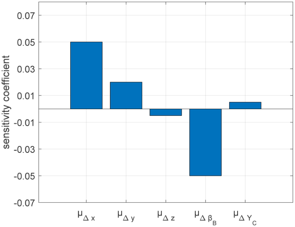
AFOSM method mean sensitivity.
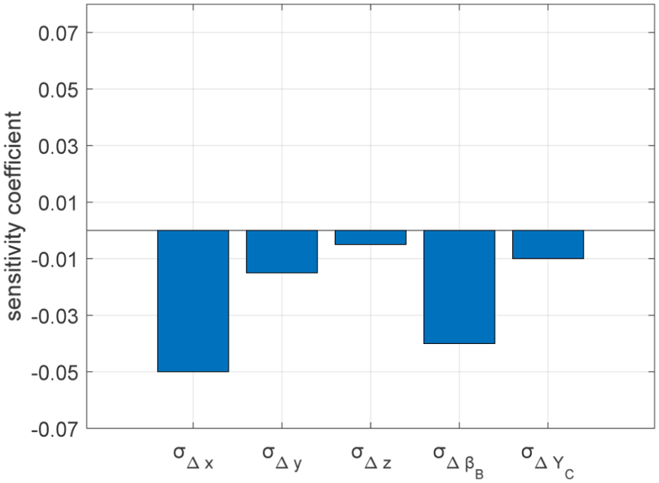
AFOSM method standard deviation sensitivity.
Then, the Monte Carlo method is used to calculate the sensitivity of the reliability probability of the machine tool to the mean and standard deviation of the error random variables, as shown in Figures 11 and 12.
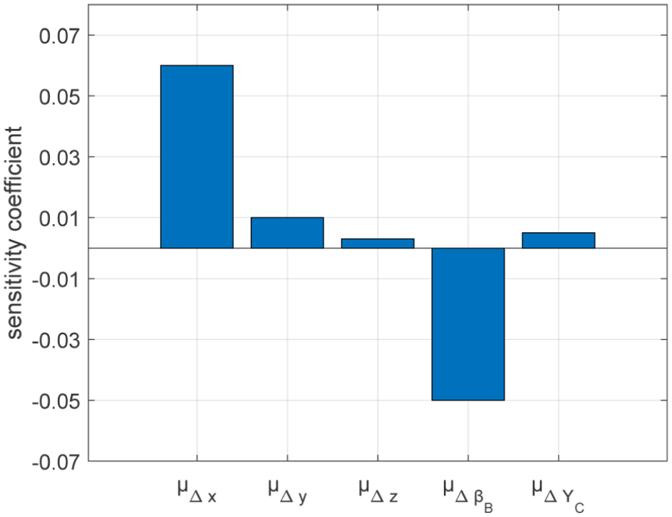
Monte Carlo method mean sensitivity.
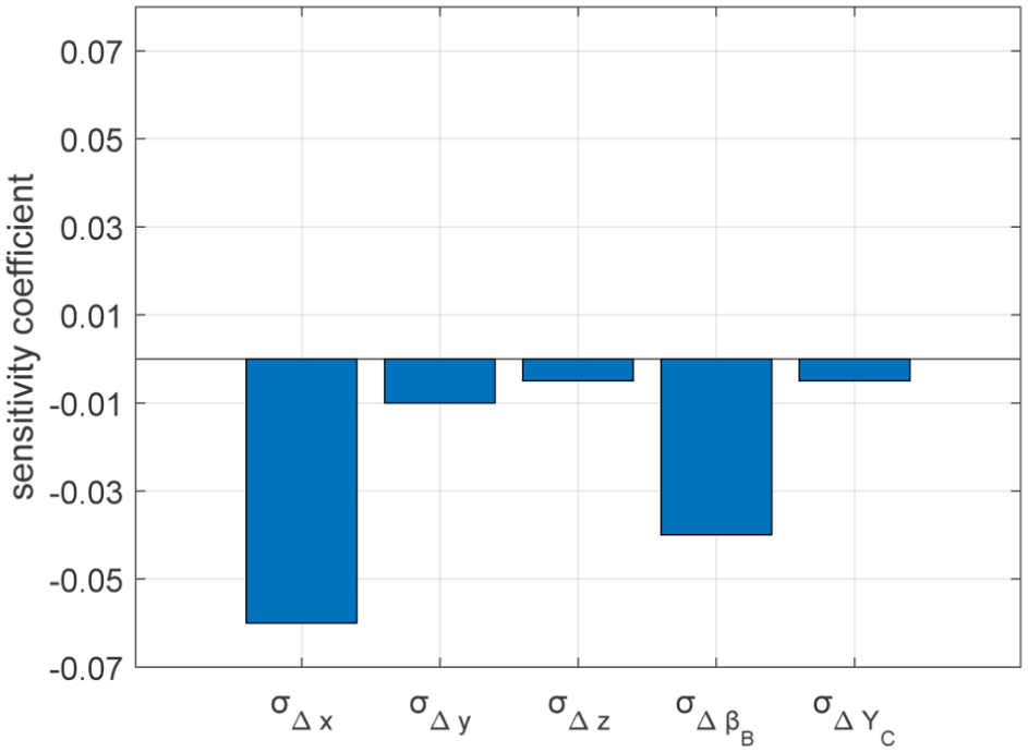
Monte Carlo method standard deviation sensitivity.
As can be seen from Figures 7 and 8, the kinematic reliability of the machine tool using the AFOSM was generally consistent with the trend obtained using the Monte Carlo simulation sampling method, with a small numerical difference, and the combined direction reliability was close to the theoretical limit. This indicates that the initial positional accuracy and structural design of the machine tool were reasonable. Therefore, the accuracy of using the AFOSM to calculate the kinematic reliability of the special machine tool for VH-CATT cylindrical gears was acceptable.
From Figures 9 to 12, it can be observed that the sensitivity trends of the mean and standard deviation of machine tool variables calculated using AFOSM method and the Monte Carlo method are essentially consistent. This suggests that the accuracy of calculating machine tool reliability sensitivity using the AFOSM method is acceptable.
Mean sensitivity reflects how the kinematic reliability of a machine tool responds to small changes in the mean value of an error source. These drive translational errors Δx, Δy, Δz directly affect the absolute position of the tool or workpiece in the X, Y, and Z directions. If the drive system has a systematic offset (e.g. due to inaccurate sensor calibration, accumulated lead screw pitch errors, guide rail mounting deviations, etc.), even a small mean deviation will lead to an overall offset in the machining trajectory. This systematic offset directly accumulates into the final machining error, thereby reducing kinematic reliability. These drive rotational errors Δβ B , Δγ C represent systematic angular deviations in the B-axis and C-axis rotational drives. The mean sensitivity of rotational errors is often more complex because they affect the end position of the tool or workpiece through a lever effect (i.e. the error magnifies with distance). For gear machining, systematic deviations in rotational errors can lead to systematic deviations in tooth profile or tooth direction, severely impacting meshing performance. From Figures 9 and 11, it can be seen that the absolute values of the mean sensitivities for Δx and Δβ B are relatively large, indicating that systematic deviations (i.e. the mean value deviating from the ideal value) in these two error sources significantly impact the kinematic reliability of the machine tool.
Standard deviation sensitivity reflects how the kinematic reliability of a machine tool responds to small changes in the variability (randomness) of an error source. The standard deviation of these drive translational errors Δx, Δy, Δz represents the random jitter or instability of the drive system in the translational directions. Examples include random fluctuations in servo system response, random changes in guide rail friction, and random fluctuations in ambient temperature. A larger standard deviation means that the position of the tool or workpiece will randomly deviate from the target position during machining, leading to increased uncertainty in the machining trajectory. This random error causes the dimensions or shapes of the manufactured parts to be statistically dispersed; even if the mean value is accurate, the random fluctuations might exceed the allowable error range, thereby reducing reliability. The standard deviation of these drive rotational errors Δβ B , Δγ C represents the random jitter or instability of the rotational drives. Examples include random errors in encoder readings, random fluctuations in motor torque, and random clearances in the transmission chain. Random fluctuations in rotational errors also affect the randomness of tool posture and cutting point position through a lever effect. For gear machining, random jitter of the rotating axis can lead to increased tooth surface roughness, irregular tooth profiles, or random deviations in tooth direction, thereby reducing the transmission accuracy and reliability of the gears. From Figures 10 and 12, it can be seen that the absolute values of the standard deviation sensitivities for Δx and Δβ B are relatively large, indicating that the random variability of these two error sources significantly impacts the kinematic reliability of the machine tool.
Therefore, for errors with high mean sensitivity, systematic error compensation (such as software compensation or hardware adjustment) can be considered. For errors with high standard deviation sensitivity, it is necessary to strengthen control over the stability of the drive system to reduce random fluctuations, for example, by improving servo control, reducing friction, or implementing vibration isolation.
Conclusions
The research conducted an in-depth analysis and evaluation of the kinematic accuracy reliability of a special machine tool for VH-CATT cylindrical gears, providing important theoretical basis and engineering guidance for improving the machining accuracy and service life of such complex machine tools. By introducing reliability assessment methodologies, this research not only validated the applicability of existing theories but also revealed key factors affecting machine tool kinematic reliability and pointed the way for future precision design and error compensation strategies.
(1) One of the core contributions of this study lies in combining traditional kinematic reliability design theory for mechanisms with an improved AFOSM method, successfully applying it to the kinematic accuracy reliability analysis of the VH-CATT cylindrical gear special machine tool. An error calculation model for the machine tool was established using coordinate transformation and multi-body system theory. Based on this, the AFOSM method was used to calculate the kinematic reliability and sensitivity of the machine tool in the X, Y, and Z directions, as well as in the combined direction. To ensure the accuracy of the calculation results, the Monte Carlo method was further employed for verification. The research results indicate that the initial positioning accuracy and structural design of the machine tool are reasonable, as the kinematic reliability calculated by the AFOSM method is generally consistent with the trend obtained by the Monte Carlo simulation sampling method, and the combined direction reliability is close to the theoretical limit. This fully demonstrates the effectiveness and applicability of the AFOSM method in calculating the kinematic reliability and reliability sensitivity of this type of machine tool. This validation not only enhances the credibility of the AFOSM method in dealing with nonlinear performance function problems but also provides an efficient and accurate tool for reliability assessment of complex electromechanical systems in the future.
(2) The research conducted a systematic error analysis of the machine tool, considering only drive errors. By calculating and comparing the mean sensitivity and standard deviation sensitivity, key factors among the drive errors that affect the kinematic reliability of the machine tool were identified. The research findings provide clear guidance for the precision design and error compensation of machine tools. For errors with high mean sensitivity, systematic error compensation (such as software compensation or hardware adjustment) should be prioritised; for errors with high standard deviation sensitivity, it is necessary to strengthen control over the stability of the drive system to reduce random fluctuations (such as improving servo control, reducing friction, or implementing vibration isolation).
(3) The research provides a solid theoretical reference for error compensation and accuracy synthesis research of VH-CATT cylindrical gear special machine tools, and offers valuable insights for the kinematic accuracy analysis and design of other types of machine tools. Although this research only focuses on the impact of drive errors on the kinematic accuracy reliability of machine tools, its established analytical framework and verification methods have broad applicability. Future research will build upon this foundation to further explore the effects of geometric errors, thermal errors, and other factors on the kinematic accuracy reliability of machine tools, in order to construct more comprehensive and accurate machine tool reliability assessment models. This will provide stronger technical support for VH-CATT cylindrical gear special machine tools and the broader field of precision manufacturing. Through continuous and in-depth research, it is expected to significantly improve the machining quality of machine tools, extend their service life, and ultimately promote the development of high-end CNC machine tool technology.
Footnotes
Handling Editor: Cuneyt Fetvaci
Funding
The authors disclosed receipt of the following financial support for the research, authorship, and/or publication of this article: This research was funded by the Talent Introduction Project of Mianyang Polytechnic (MZ22RC01), and the National Natural Science Foundation of China (51875370).
Declaration of conflicting interests
The authors declared no potential conflicts of interest with respect to the research, authorship, and/or publication of this article.
Data availability statement
All the data used in this article can be obtained upon request from the corresponding author*.