
Abstract
Electric vehicles (EVs) are becoming a key solution to sustainable transportation due to their potential to reduce greenhouse gas emissions, improve energy efficiency, and support renewable energy integration. However, the rapid growth of EV adoption introduces significant challenges related to charging infrastructure, battery technologies, energy management, and power grid integration. Motivated by the need for a comprehensive and unified understanding of these interconnected aspects, this paper presents an integrative review of the recent advances in EV technologies and renewable-energy-based charging systems. The review analyzes more than 100 publications from international journals and conferences, covering EV technologies, intelligent energy management, charging infrastructure, battery challenges, grid integration, and renewable energy penetration in different countries. The study also evaluates the economic and environmental impacts of integrating renewable energy sources such as solar and wind into EV systems. The findings reveal that high renewable energy penetration scenarios can significantly improve sustainability outcomes, with wind and solar contributing up to 30.86% and 26.45% of electricity production, respectively, while reducing CO2 emissions by 22.5% and lowering operational costs by 12%. The review further highlights the economic and environmental advantages of EVs over conventional vehicles, while identifying critical challenges associated with battery lifespan, energy density, charging infrastructure, and grid stability. In addition, the paper discusses future research directions and policy recommendations to support large-scale EV deployment and sustainable transportation development.
Introduction
The automobile industry is one of the most critical global sectors today, both economically and in terms of development and research. More technological features are being incorporated into automobiles to enhance human safety. In line with the file, the European Union is responsible for almost 28% of today’s total CO2 emissions. Road transport accounts for over 70% of shipping-area emissions. 1 Governments worldwide have implemented several limits on carbon dioxide and nitrogen oxide emissions as environmental issues worsen. 2 In the automotive sector, there may be a noticeable shift from combustion-engine vehicles (ICEVs) to electric vehicles (EVs). EVs are the best alternatives to ICE cars since petroleum is their primary fuel and plays a significant role in an environmental catastrophe.3,4 These internal combustion engine (ICE) cars utilize cutting-edge electronic power systems and smart grids. EVs can be split into hybrid electric vehicles (HEVs) and plug-in hybrid electric vehicles (PHEVs). EVs depend on system content and current state-of-the-art electrical design. In recent years, industrialized nations have built several economic factors as an intelligent approach to assist businesses and research projects in electrical engineering. Indeed, the power electronics sector and its infrastructure have rapidly expanded during the past 10 years.5,6 The EV is a massive step in improving the quality of the surroundings. EVs recharge their batteries. These batteries no longer control the vehicles but are applied to the lights and wipers. The batteries of electric cars have a better gasoline financial system and lower gasoline expenses than traditional fuel cars. The same battery is often used while the diesel engine is running.
The ICE and the tank are replaced with an electric motor that runs on batteries. When the car is not in use, it is connected to a charging station. It has many benefits: it’s pretty efficient, produces no tailpipe emissions, which keep the local air clean, has good acceleration, and can be charged in a single day using low-cost energy generated by any modern power plant, including renewables. 7 But despite these advantages, battery-electric vehicles (BEVs) also face significant challenges. Storing electricity is still expensive, and charging the battery takes a long time. For this reason, the range of these compounds is restricted. The impact of BEVs on the grid can be adverse. Their high capital costs are a deterrent to consumers, and their low operating fees result in low visibility. This hassle is caused by insufficient charging infrastructure. 8 However, the roadmaps drawn up by most governments envision battery-powered EVs playing a vital role, given their immense potential for technological advancement. Moreover, new business models have evolved to address contemporary risks, and guidelines have been implemented to support their development. 9 It is known that the rewards of EV are apparent.1–9 There hasn’t been a better time to switch to an EV, thanks to the development of new technologies that promise to cut charging times in half, boost range, and achieve adequate security and efficiency. Figure 1 indicates the numerous advantages of using EVs. 2 Moreover, the detailed system architecture, including renewable energy systems, EV and grid interactions, and conversion devices, is shown in Figure 2. The energy flow diagram for the system architecture is depicted in Figure 3.
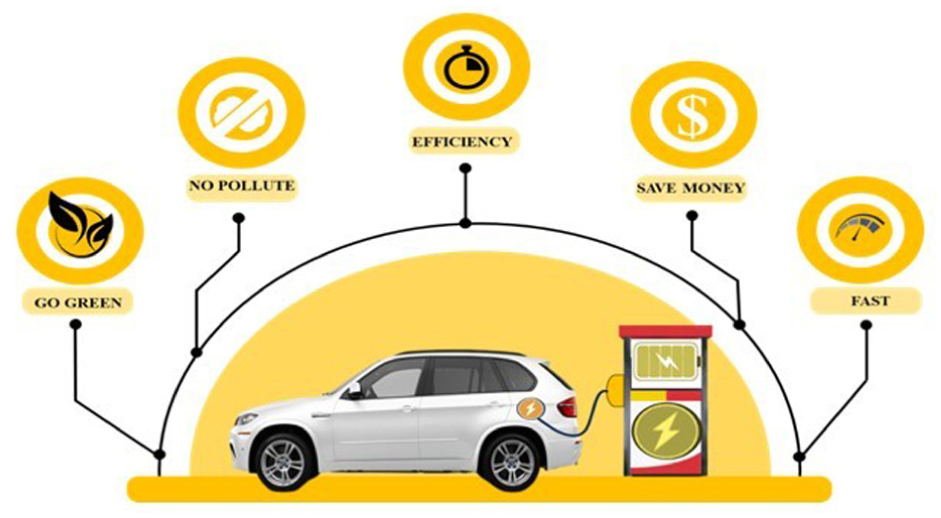
Several benefits of electric vehicles.
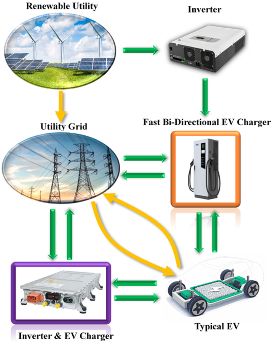
Detailed system architecture diagram.
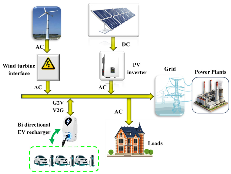
Energy flow diagram.
The electrical motor uses 90%–95% of the energy supplied to operate an EV. The charging port, battery, charger, DC/DC converter, power electronics controller, regenerative braking system, and drive system are essential parts of an electric car. The charger’s job is to convert AC power from the power source into DC energy so that it can be used to charge the battery. While the battery is charging, it also monitors its voltage, current, temperature, and state of charge (SOC). Also, to power the vehicle’s accessories, the DC/DC converter converts high-voltage DC from the battery to low-voltage DC. By controlling the flow of electricity from a traction battery, a power electronics controller controls the torque and speed of the traction motor. 10 To reduce the overall system weight and space, designing charging and traction circuits in an EV is crucial. The same inverter is meant to be used by both charger and traction to provide power flow in both directions. And yet, a charger may be segregated to reduce noise in standard mode, making it challenging to integrate the traction converter and charger. Additionally, the grid expects the EV to supply vehicle-to-grid (V2G) services to mitigate electrical power fluctuations as the EV market develops. As a result, there is more interaction between the EV and the grid, as shown in Figure 2, where limits on noise in standard mode or on DC injection into the grid have been established by some standards. 11 Therefore, to significantly minimize common-mode noise in both V2G mode and charging, a system uses a four-wheel-drive EV’s traditional parallel traction design. There is no need for additional switches, which reduces the device’s cost. 12 In Veza et al., 13 the paper demonstrates the growth of EVs, driven by environmental concerns and the shift away from ICEs. Using a bibliometric analysis of research from 1990 to 2022, it focuses on trends in EV policies, charging infrastructure, battery technology, and vehicle-to-everything systems (V2X). The study stresses the need for advancements in battery technology, synchronized global policies, and intelligent charging technologies 13 (see Table 1). Besides, Ampah et al. 14 highlights the integration of renewable energy (RE), including wind, solar, EVs, power-to-gas (hydrogen), and storage of pumped hydro to achieve higher penetration of RE at lower costs (see Figure 3). The high renewable energy penetration (HREP) scenario predicts wind and solar contributing 30.86% and 26.45% to electricity production, compared to 2.36% and 1.78% under BAU. This technique reduces emissions of CO2 by 22.5%, costs by 12%, and creates 723 jobs while avoiding 11.96 Mt of emissions for CO2. 14 The study in Ampah et al. 14 underlines the importance of this strategy for the transition of Ghana to a low-carbon and sustainable energy in the future. In Ampah et al., 15 this paper offers solutions for RE to address the challenges of EV adoption in sub-Saharan Africa, with a focus on Ghana. Moreover, the safety issue of lithium-ion batteries, focusing on mechanisms of failure and machine learning methods for forecasting and managing faults, is discussed in Zhao et al. 16 It presents advances in unsupervised, supervised, and physics-informed learning models to enhance reliability and safety across applications, from devices to energy storage systems. The authors in Zhao et al. 16 highlight the importance of data-driven methodologies for improving battery prognostics and diagnostics. In addition, accurate estimation of lithium-ion battery (LIB) parameters, such as state of health (SOH), remaining useful life (RUL), and state of charge (SOC), to guarantee optimal performance is presented in Pandey et al. 17 The challenges of diagnosing LIB health and forecasting degradation, emphasizing the impact of cell-to-cell variability and changing operating conditions, are discussed in Thelen et al. 18 Table 1 presents samples of published papers, including their aspects, descriptions, key findings, research gaps, limitations, and taxonomy clusters.
Samples of published papers with their aspects, descriptions, critical findings, research gaps, limitations, and taxonomy cluster.

ESS: energy storage systems; EVSE: EV supply equipment; G2V: grid-to-vehicle; HREP: high renewable energy penetration; HRES: hybrid renewable energy system; LIB: lithium-ion battery; ML: machine learning; RE: renewable energy; V2G: vehicle-to-grid.
The study in Zhang and Teh 19 examines a unified analysis framework for integrating dynamic line rating (DLR) and vehicle-to-grid (V2G) technologies to alleviate grid congestion and the variability of wind power. It offers an extensive examination of factors leading to curtailment, an assessment of advanced monitoring systems, and a framework to address gaps in behavior-oriented modeling, optimal dispatch, and governing policies to improve the resilience of the smart grid. Moreover, in Tan et al., 20 the authors conducted a comparative analysis of EV competitiveness against internal combustion-powered traditional vehicles across key worldwide markets, focusing on infrastructure, performance, social acceptance, and policy. It discovers obstacles to approval and suggests practical strategies to improve purchase incentives, supply chains, and charging networks. The research establishes a roadmap for policymakers to accelerate the transition to carbon neutrality and sustainable transportation. In Ye and Teh, 21 the study provides a logical review of dynamic thermal rating (DTR) by analyzing 141 publications to assess its role in reducing grid congestion and integrating renewable energy. It examines the principles of DTR, sensing technologies, and prediction within cyber-physical systems, identifying key gaps and trends in current research. The approach provides a considered roadmap for future improvements in the utilization of thermal capacity and grid resilience. Besides, the study in Su et al. 22 proposes an optimal dispatching strategy for AC/DC systems in hybrid distribution networks with EVs, leveraging cooperation among cloud, edge, and devices. To overcome data delays, it uses a dispatch technique to ensure voltage stability. The system successfully optimizes the integration of the renewable system while balancing the performance of the economic and social-technical grids. A coordination process for wind energy integration in microgrids based on a dual-methodology technique that leverages EV scheduling and dynamic thermal line rating is proposed in Song and Teh. 23 . Authors in Song et al., 24 propose a reliability model using a novel security index that integrates V2G and dynamic thermal line rating (DTLR) to mitigate wind intermittentity. The suggested structure significantly enhances the stability and security of power systems incorporating renewable energy sources, as evaluated using metrics for the IEEE 24-bus system. In Yang et al., 25 the research provides a framework for evaluating the power grid’s vulnerability to extreme weather by comparing the tasks required for the systematic and chaotic charging processes of EVs. It integrates artificial neural networks to estimate battery degradation and uses Monte Carlo simulations to account for weather uncertainties. The suggested model is highly generalizable to complex smart grids and effectively identifies critical failure points, validated across multiple IEEE bus systems. The study in Sun et al. 26 discusses the impacts of EV integration on grid reliability and analyzes optimization strategies and V2G. In order to reduce the risks associated with uncoordinated charging. To assess the synergy between DTR technology and renewable energy, this paper proposes a comprehensive model that considers distribution, transmission, and generation. Moreover, the analysis of DLR models, with discussion of the lack of coordination with EVs and DER, is a major and vital research gap in Itodo et al. 27 It offers a hybrid structure that merges machine learning and real-time optimization to achieve a balance between dynamic power and improved integration of the renewable system. In addition, the paper helps as a strategic roadmap for emerging sustainable, adaptive, and flexible power systems.
The analysis of the EV ecosystem for integrating V2G and energy management based on artificial intelligence (AI) is provided in Satpathy et al. 28 The analysis identifies significant gaps in infrastructure interoperability, battery recycling, and cybersecurity. The review offers a roadmap for policymakers and researchers to facilitate the transition to an intelligent systems framework for EVs. 28 However, the participation of EVs in carbon and electricity markets, taking into account market-clearing algorithms and bidding strategies, is evaluated and discussed in Lei et al. 29 It also analyzes global enterprises and regulatory frameworks to help reduce emissions and trade in decentralized energy. As a result, it recognizes future requirements for the efficient and sustainable integration of the EV-grid market. 29 Moreover, a grid-forming (GFM) controller-based MATLAB package is proposed in Acharige et al. 30 to address thermal and power-quality issues for EVs. It improves the stability of frequency and voltage via demand response and smart charging, guaranteeing the reliability of the distribution grid. 30 In addition, authors in Satpathy and Ramachandaramurthy 31 propose a multi-layered AI framework for the resource of distributed energy management systems, confirming the use of reinforcement learning and deep learning through analysis of economic factors, and recognizing privacy and AI as important challenges for robust networks. 31 In addition to these studies, there are many other studies that have focused on various aspects of EV, such as energy sources, topology of power conversion, the impact of charging stations, energy storage systems in batteries, hybrid EV, battery technology, lithium acid, and charging strategies, as given in sources.32–39
Based on the proposed quantitative and taxonomic comparisons in this review paper, several important insights have emerged. First, research on EVs is transitioning from hardware-focused improvements toward AI-driven systems and well-defined software, particularly in battery management and energy optimization.16–18,31 Second, the charging infrastructure is evolving from passive systems to grid-interactive platforms that support bidirectional energy flow and market participation.29,35 Third, integration with renewable energy systems (RES) presents both challenges and opportunities, requiring progressive optimization to balance the sustainability and stability of the grid.14,15,30 These findings show that future EV systems will operate as active components of smart grids rather than isolated loads, requiring multi-domain optimization and coordinated control.
The key contribution of this study is to demonstrate a structured synthesis of EV technologies through an integrated taxonomy, supported by a unified analytical framework and quantitative comparisons. This approach enables understanding of cross-domain phenomena and highlights directions for future research toward grid-integrated, intelligent EV ecosystems. In this paper, the reported values in tables represent typical ranges synthesized from multiple literature sources and studies.
Electric vehicles (EVs) have emerged as a critical technology for sustainable transportation, driven by the need to reduce carbon emissions and the reliance on fossil fuels. Despite rapid advancements, challenges persist across various aspects of EV technology, including battery performance, charging infrastructure, integration with renewable energy sources, and policy frameworks. This review aims to provide a comprehensive analysis of these aspects, addressing existing gaps and presenting the novelty of the work. Research on EV technologies has primarily focused on specific components, often without a holistic view of the entire EV system. Key areas explored in previous studies include:
Battery technologies focus on improving energy density, charging speed, and lifespan, particularly in lithium-ion batteries.
Charging infrastructure, including developing on-board and off-board charging systems and analyzing their efficiency and speed.
Integration with renewable energy, examining the potential for combining EVs with solar, wind, and other renewable sources to improve sustainability.
Global adoption and policy issues, analyzing how countries address the transition to EVs through market dynamics, government policies, and infrastructure investments.
While there is considerable research on individual components of EV technology, several vital gaps remain:
Need for further advancements in battery technologies, focusing on energy density, lifespan, and cost reduction.
More comprehensive solutions for integrating renewable energy with EVs, especially at the scale required for widespread adoption.
Development of innovative charging systems and fast-charging technologies that can reduce charging time and enhance energy efficiency without damaging battery life.
Understanding the challenges in infrastructure and policy adoption, which vary widely by region and influence the pace of EV deployment.
This review paper aims to fill the abovementioned gaps by providing a detailed and integrative analysis of EV technologies’ state and prospects. The key contributions of this paper are:
An in-depth exploration of various EV components, focusing on the latest developments in battery technologies.
A comprehensive examination of different types of EV batteries, including lithium-ion, solid-state, and other emerging technologies, and their respective advantages and challenges.
A discussion of integrating renewable energy, particularly photovoltaic (PV) systems, with EVs examines the synergy between renewable energy sources and EV technology.
An analysis of the challenges associated with battery technology, such as lifespan, energy density, cost, and the need for improved charging infrastructure.
Identify open research opportunities in EV technology, particularly in intelligent charging, energy storage, and renewable energy integration.
A review of different charging strategies, including intelligent charging and fast-charging technologies, and their potential to enhance the practicality and efficiency of EVs.
A detailed examination of traction circuits and charging systems, with insights into how these systems can be improved for better performance and efficiency.
Methodology
This paper adopts a structured literature review method to analyze recent progress in EV technologies. Relevant papers were collected from distinct scientific databases, including ScienceDirect, IEEE Xplore, Google Scholar, and Scopus. The search process was conducted using different keywords such as “infrastructure of EV charging,”“systems of EV battery,”“electric vehicles,”“challenges of EV adoption,” and “integration of renewable energy with EVs.” The selection process focused mainly on conference articles and peer-reviewed journal papers published between 2018 and 2026 to ensure inclusion of developments in recent technology. Papers were included if they addressed charging systems, battery technologies, EV infrastructure, future prospects for EV utilization, and the integration of renewable energy. Studies and research not directly related to EV technology or lacking technical impact were excluded. After screening full texts, abstracts, and titles, the most relevant publications and papers were selected and categorized into key subjects and themes: charging infrastructure, battery systems, integration of renewable energy, EV technologies, future visions, and challenges.
Energy storage system (ESS)
The ESS is considered a critical element in EVs, working as the primary power source for auxiliary and propulsion systems.32–47 Usually, ESS contains batteries with high capacity, like lithium-ion, which deliver high density of energy, durability, and efficiency. ESS allows EVs to store energy produced via charging from the regenerative braking or grid, guaranteeing reliable power transfer for extended driving ranges. Advanced designs of ESS revolve around enhancing the speed of charging, safety, lifespan, and sustainability of the environment by integrating innovations such as batteries of solid-state and radical battery management systems (BMS).43–47 ESS not only improves the performance of EVs but also shares energy efficiency and decreases carbon emissions, making it crucial for sustainable transportation solutions. Chemical batteries are the only power storage technology economically viable for EV applications. 32 The batteries are categorized into two types: non-rechargeable and chargeable primary batteries. The type of non-rechargeable batteries is primary, meaning they cannot be recharged. They are made only to be discharged once. Examples include lithium batteries used in calculators, watches, cameras, torches, and manganese dioxide batteries to power toys, radios, and other devices. 32 At the same time, the rechargeable secondary batteries may be recharged by running current in the reverse direction from how they flow during discharge.33,34 Chemical processes differ from those that occur during discharge. After charging, secondary batteries can be used again. However, the battery’s condition will deteriorate after each additional charge and discharge. The battery can only be charged and drained many times, or cycles. Secondary batteries are the only type of batteries utilized in electric vehicles. Lithium-ion batteries have become more popular due to technological advancements since lead-acid batteries were first used, yet this could change due to current research. 33 A comparison of battery technologies in terms of their cycle durability and energy density, specific energy, and working temperature is visualized briefly as in Figure 4. In this visual aid, the warm colors represent higher working temperatures (see Figure 4). Several different battery types are now employed in a variety of EVs and are commercially accessible. 34 The following discussion covers the major types of rechargeable batteries considered for EV and HEV applications. 35
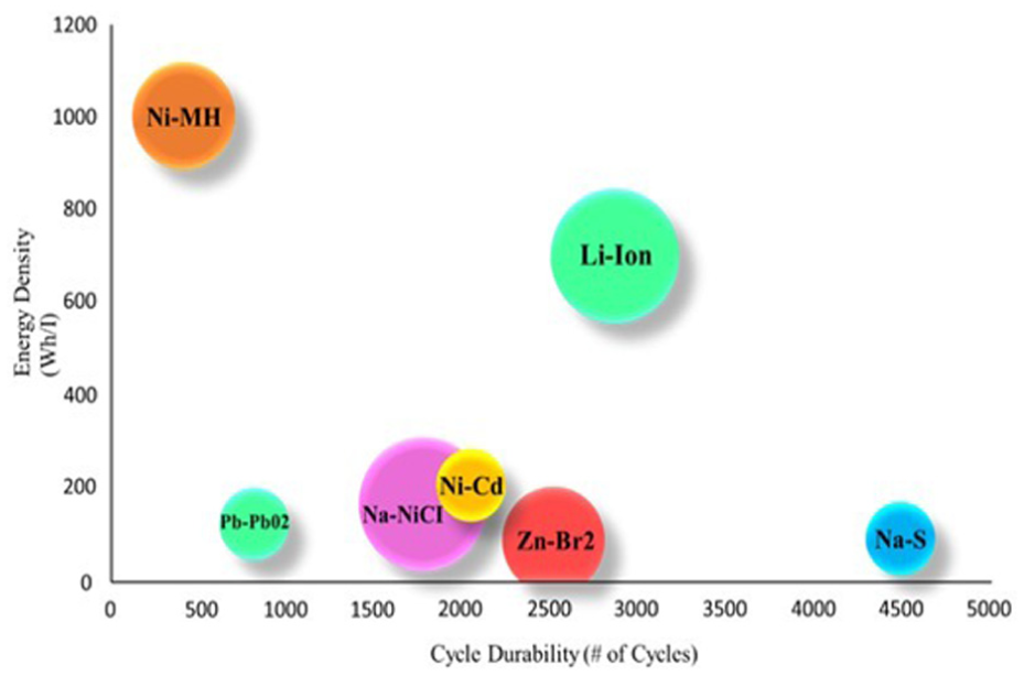
A comparison of battery technologies in terms of their cycle durability (x-axis), energy density (y-axis), specific energy (bubble size), and working temperature (bubble color). Note that warm colors represent higher working temperatures.
Lead-acid batteries (Pb-PbO2)
These batteries are the earliest type of rechargeable battery, having been created in 1859. Although it has been utilized by electric vehicles, this type of battery is prevalent in conventional automobiles. The battery comprises many lead plates and a deposit of sulfuric acid, and it has relatively low specific energy and energy density ratios. In the initial loading procedure, lead sulfate is converted to metal in the negative plates, while lead oxide (PbO2) is generated in the positive plates. These batteries were utilized in automobiles like the Toyota RAV4 EV and the GM EV1.36–38
Nickel–cadmium batteries (Ni–Cd)
Nickel–cadmium (NiCD) batteries work best at high temperatures and are suitable for applications requiring extended deep drain periods. This technology was employed in the 1990s. However, NiCD batteries’ applicability in EVs is constrained by their low energy density and significant levels of hazardous metals. Nickel-metal-hydride (NiMH) batteries are now used to replace nickel-cadmium batteries.1,39
Nickel–metal hydride (Ni–MH) batteries
These batteries offer higher energy and power densities than traditional lead-acid batteries. However, these batteries need frequent maintenance and function poorly at extreme hot and cold temperatures. These batteries are unsuitable for EV applications, as EVs require high-capacity batteries capable of multiple deep-discharge cycles.40,41
ZEBRA (Na–NiCl2) batteries
The ZEBRA battery is used in several concept vehicles and buses for city transport, sometimes called Na–NiCl2. Since this battery functions at high temperatures (300 °C–350 °C), particular containers are required; therefore, even if it may be chilly outside, the interior should be warm. 42 In addition to having a greater energy density (110–120 Wh/L), these batteries are also more affordable than the various technologies already in use. 43
Sodium sulfur batteries (Na–S)
Sodium and sulfur liquid serve as the negative and positive electrodes of a sodium–sulfur (Na–S) battery. Solid beta-alumina serves as an electrolyte.40,44,45 The negative (liquid sodium) electrode is oxidized during discharge and releases Na+ ions (a favorable state at 300 °C–350 °C). When passed through the electrolyte, these ions combine sulfur, forming sodium pentasulfide. The reverse reaction occurs during a charge cycle, and sodium pentasulfide breaks into sodium and sulfur.46,47
Lithium-ion batteries (Li-ion)
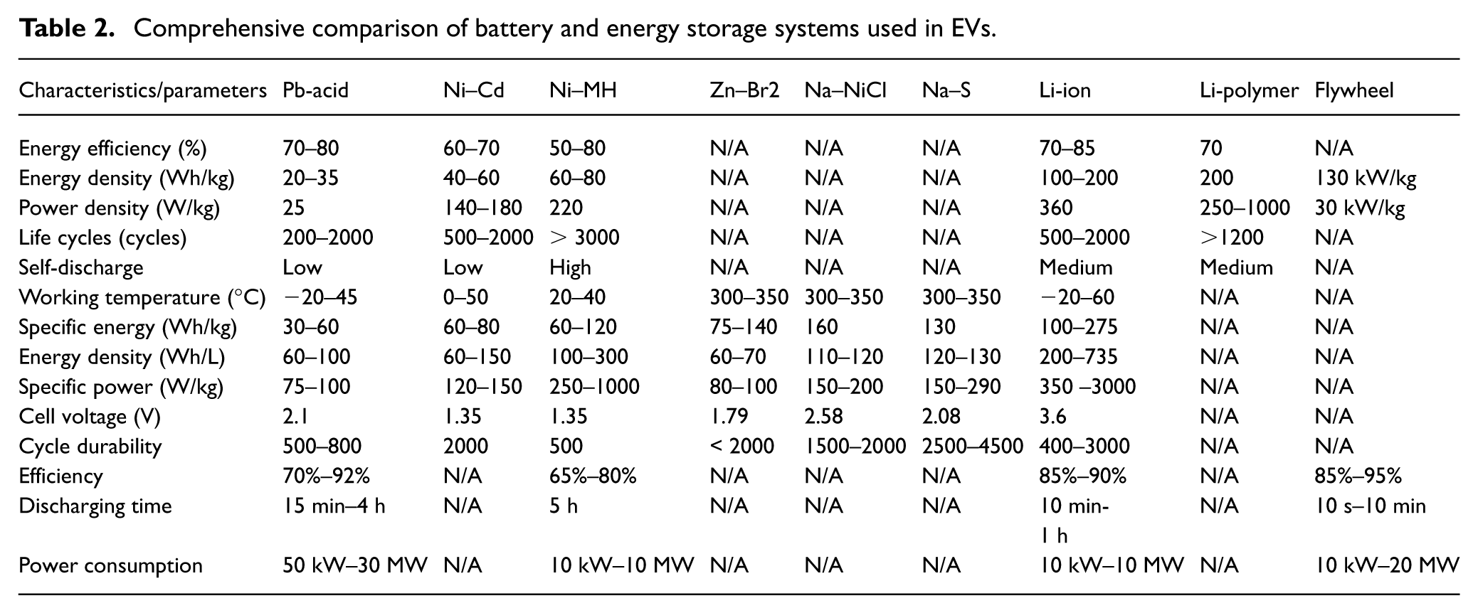
It is clear that Li-ion battery-based electric vehicles are widely accessible on the market. These days, lithium-ion batteries frequently display a charging current of around five times more than the capacity claimed, along with excellent cycle endurance.32,35,38,48 This demonstrates that speedy battery recharging is no longer a problem. Research has shown that lithium-ion batteries, which are used in electric vehicles, outperform Ni-MH batteries in terms of specific power (350–3000 W/kg) and specific energy (100–275 Wh/kg). EVs employ batteries with a distinct real-world capacity and a powerful charging capability.38–40 Table 2 shows the comprehensive comparison of battery and energy storage systems used in EVs.1,35,38
Comprehensive comparison of battery and energy storage systems used in EVs.
Challenges of electric vehicles related to the battery
The challenge of EVs with the batteries used is categorized by various factors such as driving range, charging time, battery cost, weight, bulk, and charge stations and location. The problem with driving range, when the batteries are fully charged, is that they have a range of only 200–350 km, and this problem is constantly improving. Due to the size and design of the batteries, the range of electric vehicles is constrained. For instance, the Nissan Leaf has a 364-km maximum range for driving. 49 Additionally, the Tesla Model S has a 500-mile range. 50 Moreover, for charging time, fully charging the battery may take 4 –8 h; fast charging to 80% capacity can take 30 min. Charging a high-voltage battery can take a long time, depending on the battery charge and power source. Tesla superchargers may charge up to 50% in under 20 min or 80% in 30 min. 50 While the issue of battery cost is costly, large packs of batteries are available. The weight of the battery is a significant issue in EVs. Vehicle battery packs are large and take up much room. The batteries of these types of automobiles are predicted to weigh about 200 kg based on their capacity. 1 Besides, the location of charge stations is critical to increase the use of EVs. The network of electric charging stations is sparse.1,49,50
Battery management systems (BMS)
BMS is essential for ensuring the safe and effective operation of batteries by monitoring critical parameters at the package and cell levels.16–18,51–57 Monitoring the state of charge (SOC) of battery packs, remaining useful life (RUL), and state of health (SOH) is considered a crucial task for BMS. The issue of monitoring based on BMS is presented in the design of cell-to-pack, methods of monitoring, and critical state metrics of battery.16–18,51–57
Monitoring cells in BMS helps detect imbalances and maintain cell balance throughout the pack. This design methodology optimizes the alignment of cells to growth longevity by utilizing current, voltage, and temperature data. Machine learning (ML) models have become efficient for forecasting SOH, SOC, and RUL.51–57 To increase prediction accuracy for each condition, ML techniques use historical data on cell imbalance, charge/discharge cycles, and temperature. The time-series data for voltage and current can be used to build an ML model that precisely estimates SOC, reducing errors caused by the battery’s nonlinear characteristics. For example, intelligent alchemists accelerate battery optimization and monitoring by improving prediction accuracy with noisy or sparse data.16,18,51–57
The battery state metrics are vital parameters in a BMS; the SOC measures the battery’s available capacity. The standard equation used to describe the SOC is given in equation (1). Moreover, the SOH presents the deterioration of the battery. It is frequently computed by contrasting the nominal with the current capacities (see equation 2). Degradation patterns are used to estimate RUL. Under usage patterns, the ML can expect the remaining operational life by tracking the capacity deterioration rate.18,51–57


The
The effect of data-driven ML can improve the BMS, as explained in detail in Zhao et al., 16 Pandey et al., 17 and Thelen et al. 18 In addition, this allows BMS to adapt predictions in response to real-time performance data, resulting in more efficient and effective charging, longer battery life, and improved battery safety. The parasitic capacitance problem of EVs demonstrates several design difficulties.16–18,52–57 When this problem occurs in high-voltage systems, it affects EVs’ safety, efficiency, and dependability. Moreover, causing losses of energy that decrease the overall efficiency of power, heat generation may be increased through the effects of parasitic, necessitating cautious heat control.16–18,52–57 To eliminate electromagnetic interference (EMI) that could interfere with electronic control units, these problems make the design of BMS more complex and need further insulation, shielding, and layout considerations. Maintaining the EV’s functionality, battery life, and adherence to safety regulations depends on addressing parasitic capacitance.
Charging of electric vehicles
Besides the rapid expansion of the electric vehicle market (vehicles electric, plug-in hybrid), 58 the time and characteristics of the battery charging procedure are other crucial factors. Without a doubt, users must be able to charge their vehicles quickly and easily for electric cars to prosper. To achieve this, it will be essential to establish an infrastructure that enables such quick and easy charging. This necessitates home charging and the development of fast charging stations for lengthy commutes, as shown in Figure 5. 1
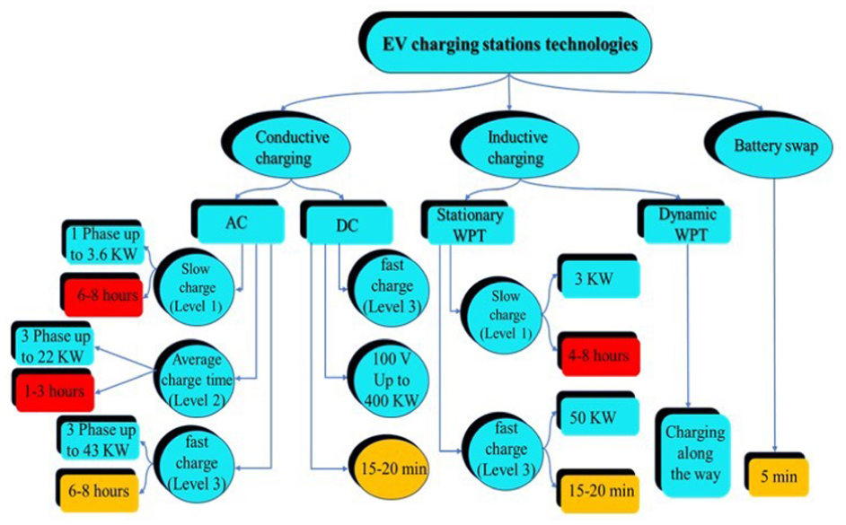
Charging stations classification.
Electric vehicle equipment of supply
The EVSE provides the power needed to recharge an electric vehicle’s battery. EVSEs are sometimes called EV charging points or charging stations for electric vehicles. EVSE consists of the conductors for electrical power, associated hardware, software, and communication protocols that transmit electrical energy from a distribution system of electric utilities into the ESS for the EVs effectively and securely. While the charging point has many charging stations, a charging pool only has one. 59 These EVSEs might be DC or AC-powered. The EVSE’s primary responsibilities are to monitor power flow and maintain a safe operating environment. AC electricity is converted to DC power to power the battery. On the other hand, DC charging alternatives feed the EV battery directly after converting a grid’s AC power to DC power off-board. Compared to AC charging, this enables higher power levels for charging. 58 The charging issues could be described in a few definitions, including charging pools, charging stations, charging points, and connectors.
A charging pool is established based on making a parking space with one or more charging stations. One operator of the charge point (CPO) and a GPS coordinate are used to operate the charging pool at a specific place. The cartographic viewpoint, navigation tools, and qualities that reflect a map’s charging infrastructure are all linked to the charging pool. 60 Besides, an actual building with one or more charging stations and a shared interface for user identification (UII) is called a charging station. While some charging stations are merely “Plug and Charge,” with no buttons, displays, or other controls, others are RFID readers, screens, and LED charging stations. 61 In addition, the charging point transmits the electric energy to the EV. A charging station may have one or more connections to support various connector types. One connection at a time is utilized. 35
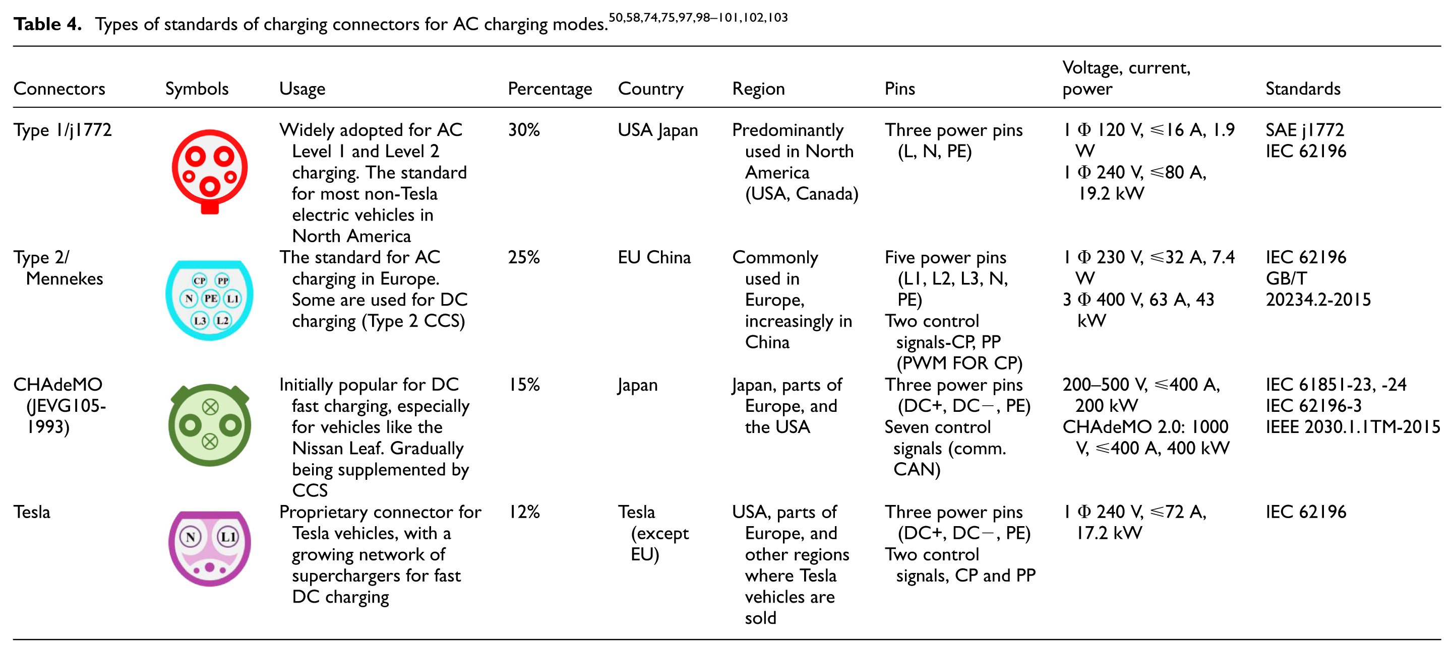
The shape and type of connectors are considered vital when charging EV batteries. The batteries of electric vehicles can be charged at home using conventional outlets thanks to an AC/DC converter. Charging stations for electric cars must be utilized, though, since they may deliver DC power straight to the batteries when a quicker charge is required. Through various connections, charging stations can provide power (see Tables 3 and 4). Moreover, they offer the following benefits. 62
They are sealed solutions; therefore, humidity or water will not damage them.
They carry the mechanical or electronic interception.
They make it possible to communicate with the vehicle.
Until the blocking system is triggered, electricity is not provided.
Some connectors have three-phase charging capabilities.
Electric vehicle charging modes and charging levels of stations
Three conductive charging techniques for electric vehicles, 63 charging inductively64,65 and swapping batteries.65–67 The charging modes are divided into conductive, inductive, and battery swapping. The following is a basic explanation of several charging modes:
Conductive charging
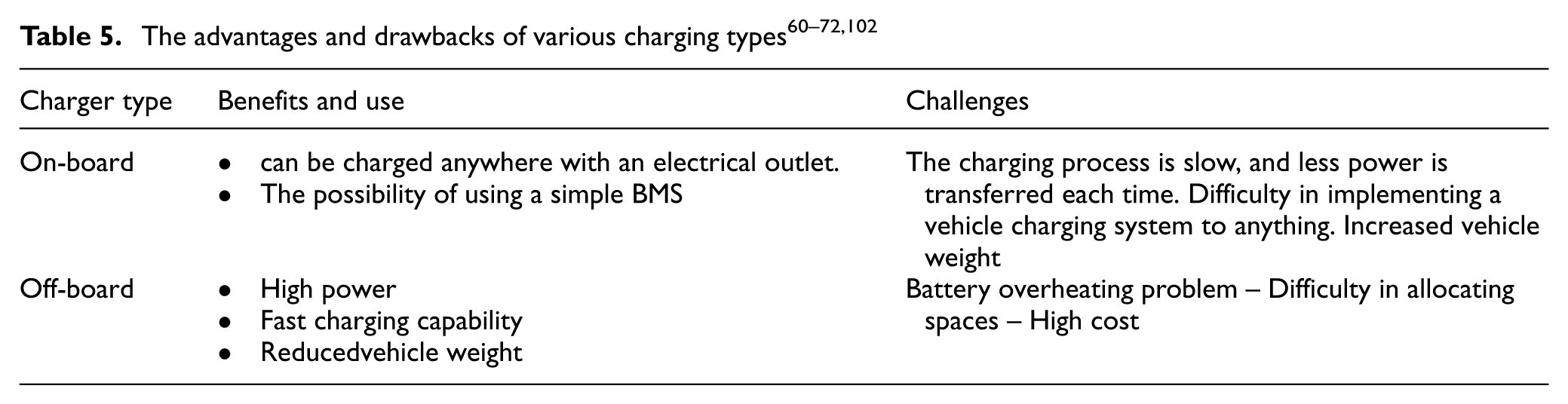
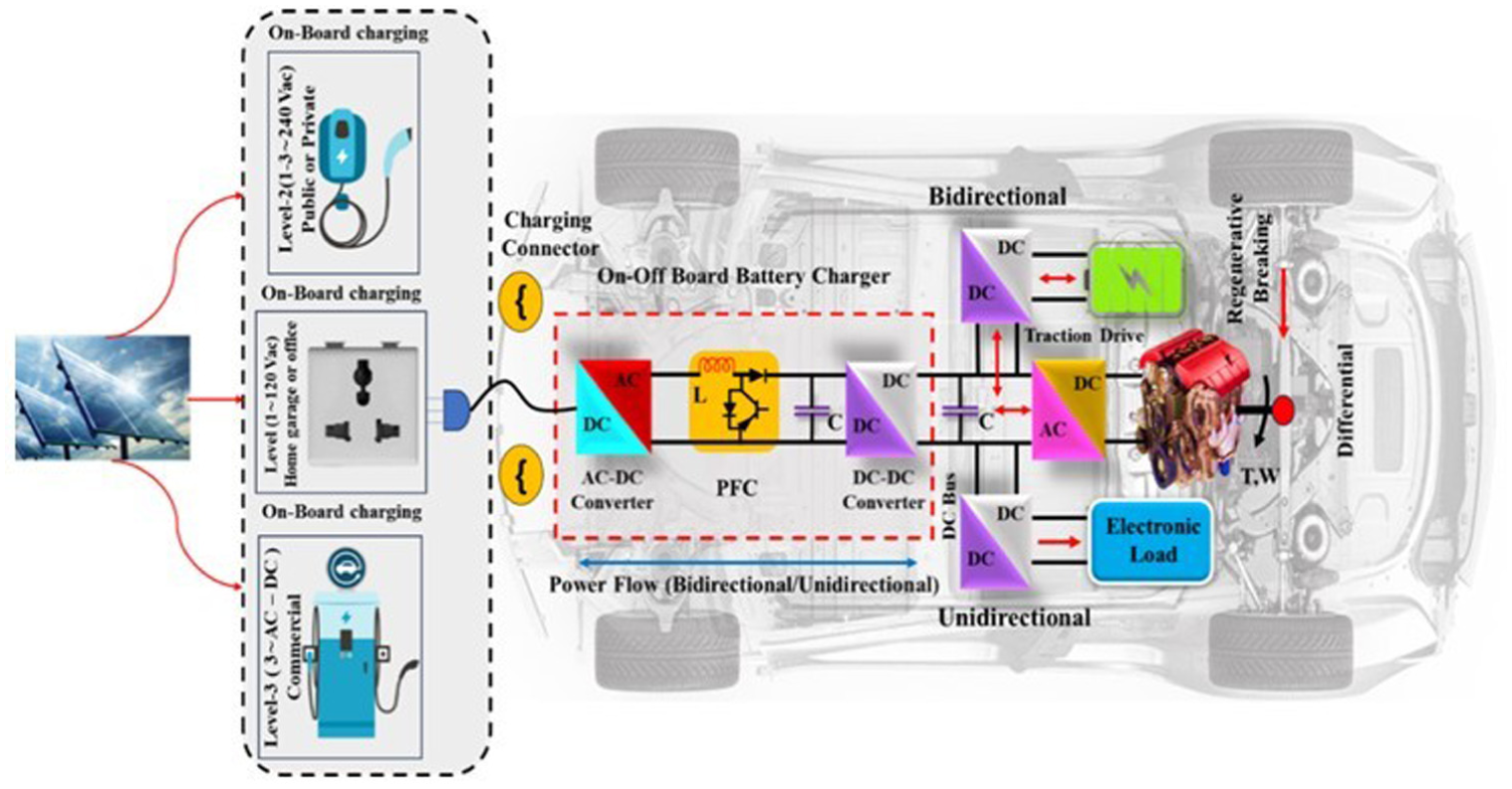
For BEVs, conductive charging is a commonly used technique. To transfer electricity, conductive charging often necessitates direct contact of metal to metal between a utility grid and an EV. This charging approach is highly dependable and successful. Conductive chargers are used in on-board and off-board charging infrastructures (see Figure 6). Due to weight, area, size, and cost limitations, on-board chargers are built into electric vehicles. However, the power output of these sorts of chargers is constrained. On the other hand, since off-board electric vehicle chargers are typically located in parking lots like those at hospitals, shopping centers, and colleges, they have different sizes, weights, and space requirements than on-board EV chargers. The block diagram in Figure 6 illustrates the differences between on-board and off-board chargers. Off-board chargers are designed for quick charging, while on-board chargers are often used for sluggish charging.68,69 Table 5 depicts the advantages and drawbacks of various charging methods.
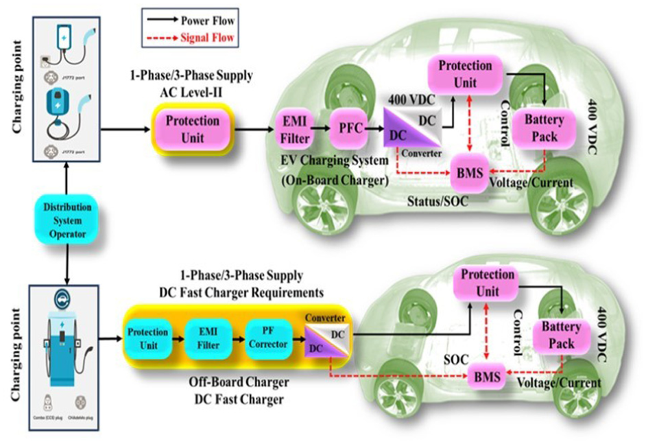
Infrastructures for conductive charging on and off the vehicle. 35
The three levels of AC or DC conductive charging are Level 1, Level 2, and Level 3. Level 3 may be mentioned only occasionally, but may be referred to as DC charging. Level 1 charging often involves low-power AC levels; Level 2 charging typically involves somewhat higher AC power levels; and Level 3, also known as fast charging using DC (DCFC), typically involves higher AC power levels.70,71 DCFC; and Level 3 charging shorten charging time. 72
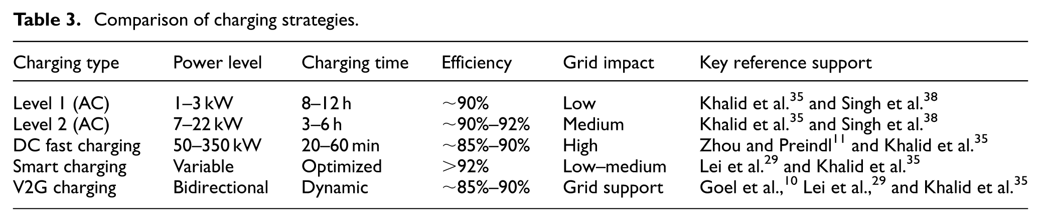
The values presented in Table 3 are synthesized from multiple works and studies in the literature, comprising9,13,16–18,33,35 and recent studies,28–31 and demonstrate typical performance ranges rather than fixed values.
Comparison of charging strategies.
Level 1 for the charger
Level 1 is for charging, and an EV charger with low energy (no more than 2 kW) onboard is utilized. With 120 or 220 V outputs, these chargers can charge an EV to a 200 km range in 20 h. Level 1 charging is typically carried out in homes and the parking spaces of residential complexes; standard electrical outlets are widely available, and charging time is long. On-board chargers are often capable of this degree of charging.35,58,73
Level 2 for the charger
In general, Level 2 chargers are AC chargers that meet the standards of Type 1 (J1772), Type 2 (Mennekes), and Tesla for AC (see Table 4). This level is based on electric vehicle on-board AC–DC chargers with higher energy ratings. A stationary charging station with a separate 208 or 240 V circuit in the branch is necessary for Level 2 charging.68,70,74
Level 3 for the charger
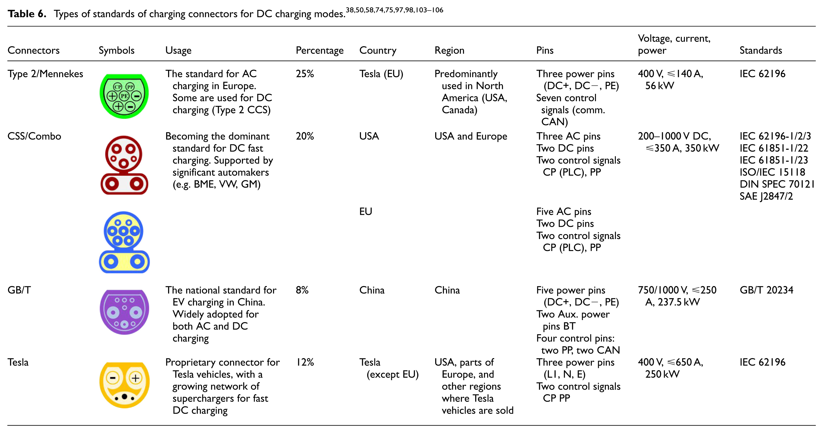
Level 3 technology of the future has the potential to minimize electric vehicle range ESS and anxiety. Typically, DC chargers that employ an off-board EVSE have substantially higher energy than Level 1 and Level 2 chargers and can charge an electric car much more quickly (in less than an hour; see Table 6). Typically, these chargers are placed on roadways. Off-board Level 3 chargers usually require a three-phase power source with a voltage of 480 V or higher. Direct DC connections to the vehicle are possible. Level 3 should meet the following standards: as shown in Figure 7, Type 2 DC (Mennekes), CHAdeMO (JEV G105-1993), Tesla for DC charging, and GB/T and CCS combo are all possible.72,75
EV charging infrastructure with EVSE arrangements. 4
Inductive charging
To transmit electricity from an EV utility grid, the inductive electricity transmission (IPT) concept is used with inductive or wireless chargers or mutual induction. 76 It does not call for any direct connection between the electric vehicle and the utility grid. 77 Furthermore, they may or may not require isolation transformers for safety reasons; therefore, they are smaller than conductive chargers. However, because the power transmission coils are misaligned, inductive chargers are comparably less efficient.35,78 There are two possible configurations for this charging. 58
Stationary charging is carried out in a parking area. Using the electric car’s multimedia system to initiate charging and manage payments would eliminate the need for terminals.
Charging for dynamic EV charging while driving is possible owing to a gadget built into the road. 79 Figure 8 illustrates the concepts of static and inductive roadbed charging for wirelessly charging EVs. Static inductive chargers have two coils: one is in the charger, and the other is an essential component. Both coils are correctly aligned to ensure maximum efficiency. Because of roadbed inductive charging, the EV can be charged while moving. In this charging method, specialized charging tracks that can charge an electric vehicle while reducing anxiety regarding range and ESS capability are installed on roadways (typically highways).68,80,81
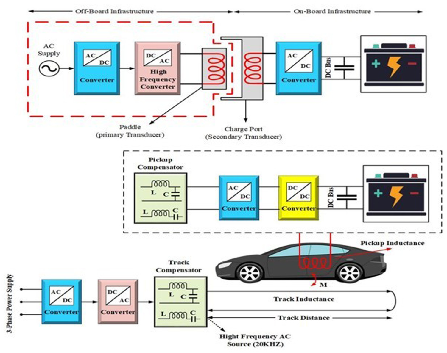
Schematic for (a) stationary inductive charging and (b) roadbed inductive charging. 35
Battery swapping
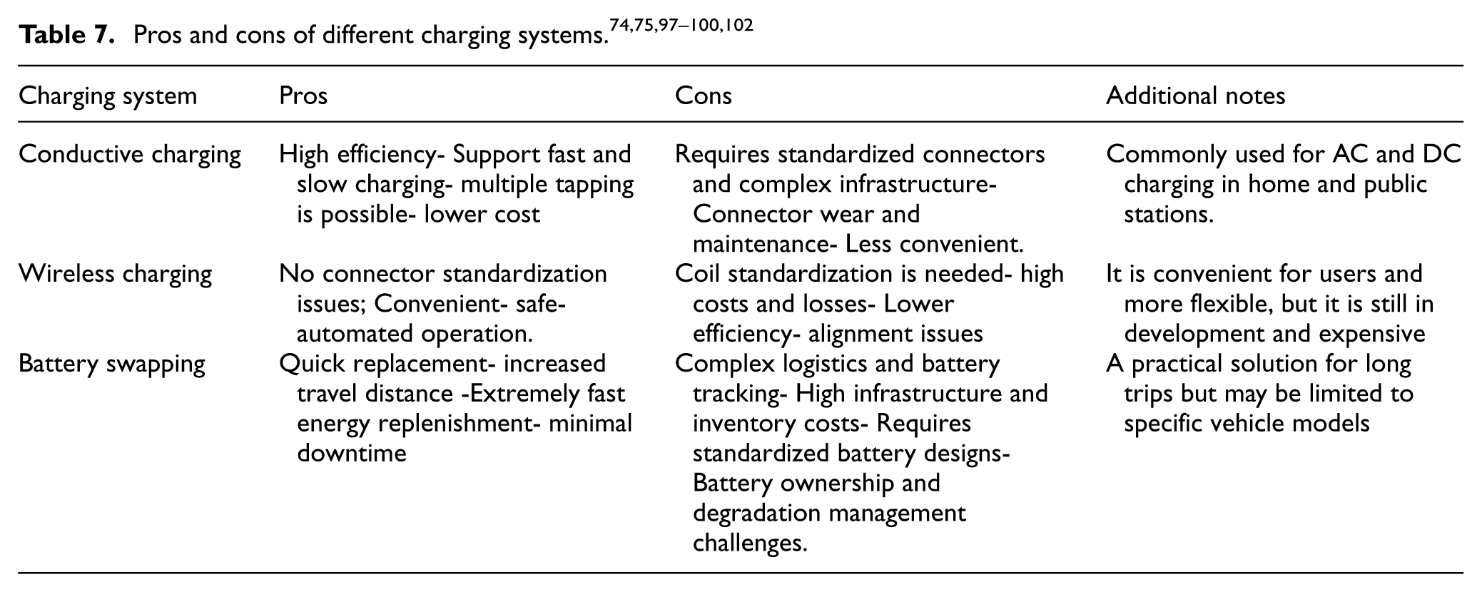
Battery swapping involves replacing the exhausted battery with a fully charged identical battery. Driving into the battery switch bay is the first step in the procedure. An automated system will position the car, detach the old battery, and install a fully charged one. Batteries that are low in power are charged at the station for future usage. According to the system’s economic model, the battery belongs to the EV user, not vice versa.66,82,83 Switching batteries is still the quickest (equal to refueling time). 84 However, this approach is exceedingly challenging to implement because batteries need to be standardized across many EV manufacturers. 85 Additionally, there are substantial logistical and financial challenges because it takes many extra batteries to supply clients 58 swiftly. The pros and cons of the different charging systems are presented in Table 7.
Electric vehicle power infrastructure
The power converter is a crucial interface between the electric vehicle and the power grid. Its goals are to enable voltage conversion and provide dependable charging and discharging control. Numerous unique power-converter topologies for EV chargers have been reported in Habib et al. 86 Depending on the number of conversion steps, an EV converter’s charging structure may be divided into one-stage or two-stage variants. Due to their sluggish charging capacity, on-board chargers often employ single-phase AC input. On-board chargers also use the two-stage technique, comprising a first-stage (AC–DC) inverter and a second-stage (DC–DC) converter. 87 A rectifier and a diode-based unidirectional (DC–DC) converter are components of the unidirectional EV charger architecture. For bidirectional chargers, use bidirectional AC–DC and DC–DC converters.38,88
The equations (3) to (5) present a synthesized mathematical framework for modeling, based on proven formulations for integrating EVs into grid studies.10,29–31,35 The relations between the power grid and EVs can be demonstrated and modeled by combining the demand of EV charging into the balance of system power (see equation (3)). The net power of the grid depends on the base demand of the load, the charging/discharging power of EVs, and the generation of renewable energy. This mathematical model forms the foundation for peak demand, stress of grid analysis, and flexibility under the integration process of large-scale EVs.

Where
In addition, V2G operation enables bidirectional power exchange between the grid and EVs (see equation (4)). The charging process occurs during periods of low demand, while the discharging process supports the grid during peak demand. Modern control strategies include price-based scheduling, real-time optimization, and control-based rules. Studies and works, for example, Satpathy et al. 28 ] and Khalid et al. 35 highlight the V2G role in supporting ancillary services and enhancing grid flexibility.

Where,
The incorporation of EVs significantly affects power flow in distribution networks (see equation (5)). Load-flow analysis must account for stochastic EV charging demand, which can increase line losses and voltage deviations. Studies in Acharige et al. 30 and Khalid et al. 35 show that uncontrolled charging can degrade grid stability, requiring coordinated charging strategies.

Where,
EV battery charger converter topologies (DC–DC)
EV converters can be divided into many types based on converter topology and modulation control. An electric vehicle charger employs two different DC–DC converter configurations: isolated and non-isolated. 89 The hardware configurations included in the battery charger design determine the switching method and appropriate control algorithm. DC–DC converters have somewhat damped dynamics and are nonlinear due to their switching properties. Therefore, a suitable DC–DC converter control mechanism is required to produce a fixed and controlled output voltage. Traditional linear controllers, such as proportional–integral (PI) controllers, can be used to regulate converters, but their performance can be improved under high load conditions. Controllers for intelligent systems overcome these issues through their fast reaction times, high dynamic performance, and robust control. The dynamics of DC/DC converters are slightly damped and nonlinear because of their switching nature. An acceptable control method for DC/DC converters is required to produce a fixed and controlled output voltage. Using customary linear regulators to manage converters. The EV battery power design chargers are shown in Figure 9.38,68,90
A battery charger’s EV power architecture.
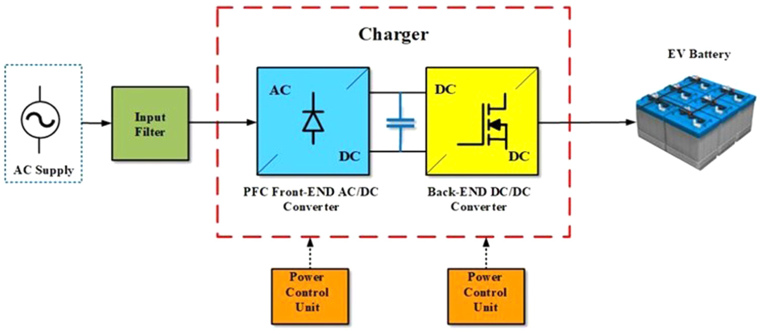
Front-end converters (AC/DC) in the first stage
For input, front-end converters are linked to a power supply, the input filter. Current harmonics are eliminated using an input filter. The EV charging system employs a variety of converter topologies, such as AC–DC, DC–AC, AC–AC, and DC–DC, depending on the specific application. These converters were created using two separate converter stages. Rectification is the first step in producing a medium-level DC voltage. A front-end converter is necessary for the PFC technique to generate a power factor close to unity. A back-end converter supplies the necessary isolated DC voltage for the EV battery. In the example of a two-stage converter shown in Figure 10(a), the AC–DC front-end (Level 1) is implemented as a six-switch converter, while the DC–DC back-end (Level 2) is implemented as a full-bridge converter.

(a) Three-phase AC–DC power converter of a two-stage, (b) three one-phase units are employed as a three-phase converter, (c) converter front-end with four switches, and (d) topology for Vienna rectifier.
PFC stage: To solve the problem of harmonic current on the grid, a PFC circuit is repeatedly inserted between the rectifier and the DC–DC stage, and the DC link voltage is stabilized. The PFC regulates input currents to become compatible with their corresponding grid voltages by first detecting input voltages and currents before turning the switch on and off. Figure 10(b) shows the inductor (L), the active switch (S), and the free diode of the conventional PFC circuit.
On the other hand, there are well-known converter-to-front-end configurations with fewer switches, such as the Vienna rectifier and the four-switch front-end converter, shown in Figure 10(c). Each converter leg uses two switches, and the third leg uses two capacitors. The center of each leg is linked to one phase of a three-phase source. The fundamental idea behind this converter’s operation is that if the phase currents between the legs for the converter with switches are somehow controlled, the phase current of the third leg, which lacks switches, can be constrained through the phase current of the other two legs, causing the currents to become sinusoidal with the voltage of phase.62,91,92
A Vienna rectifier is the other essential front-end converter arrangement, as seen in Figure 10(d). It has three primary power switches and 18 diodes. Each power switch is wired with four diodes to enable bidirectional operation and allow electricity to flow.
In both directions. Although this converter has only one bidirectional switch per converter leg, rather than two unidirectional switches, it can operate similarly to a typical converter with six switches. Better efficiency, lower voltage component stress, reduced EMI, cheaper cost, better power density, fewer switches, lower input inductance, and improved reliability are notable advantages of a Vienna rectifier. 91 The restricted control for reactive power and the requirement for DC-link condenser voltage arbitrage are the key restrictions, though.92,93
Back-end DC–DC converters of second stage
The AC–DC rectifier front-end and DC–DC converter back-end designs are the most commonly used for charging electric automobiles. The front-end architecture uses PFC to complete the rectification process, and the back-end DC/DC converter adjusts the voltage to a level suitable for electric vehicle battery charging. Given that the input side of the back-end converter gets a high regulation voltage of DC, such as 750 V, the converter chosen must be able to control the current output between 50 and 350 A. Significant challenges must be addressed when developing an EV battery charger, including increased efficiency, lower prices, higher power density, isolation, and compliance with safety requirements.38,91–93
Charging and traction circuit
The design of an EV system’s traction and charging circuits is crucial. To decrease system space and weight, the charger for the batteries and the traction process are expected to partner with the converter to provide bi-directional power flow. Therefore, a charger could be segregated to reduce common-mode noise, making integrating the traction inverter and charger challenging. Additionally, the grid expects the EV to have V2G capability to mitigate grid power fluctuations as the EV market develops. As a result, there is more interaction between the electrical grid and EVs. The grid is grounded, so there is a familiar noise of mode between the ground and the EV circuits during charging and V2G mode. This noise might endanger the system’s safety. Several standards limit the injection of DC into the grid or common mode noise. Even though a transformer may block out noise, its volume and weight will significantly increase. Therefore, common-mode noise reduction must be considered in the design of EV chargers to ensure compliance with requirements.11,12,35,38,49,58
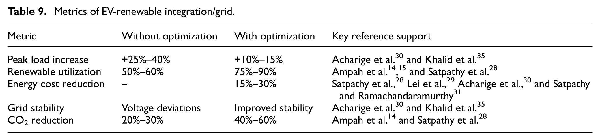
Moreover, optimization methods are widely used to coordinate EV charging with grid conditions and renewable energy availability. The main aim is normally to minimize the operational emissions cost or peak load, subject to constraints such as grid charging limits and battery capacity. Advanced techniques include multi-objective frameworks 31 and AI-based optimization, enabling decision-making in real-time for smart grids. Furthermore, EVs are progressively incorporated with RES to improve sustainability. Distinct control-based coordination enables EVs to absorb excess generation from the renewable system and provide distinct support for storage. Research such as Ampah et al., 14 Ampah et al., 15 and Satpathy et al. 28 highlights hybrid systems integrating EVs with hydrogen, wind, and solar technologies to enhance decarbonization and energy efficiency.Equation (6) presents the objective function for minimizing charging cost, adapted from references.10,29–31,35

Where,
Noise analysis in an integrated electric vehicle system
An integrated electric vehicle system’s common mode noise is analyzed.11,12,58–64 The charge or V2G mode current leakage for the standard mode route is depicted in Figure 11(a). An output filter, equivalent grid impedance, and parasitic capacitance between the earth and the charging mechanism for electric vehicles, along with the absence of an isolation transformer, create a channel for common-mode leakage current. The inverter’s six switches operate at a high frequency, creating a common-mode voltage called in operation.12,93,94 The corresponding circuit of an inverter for three phases is shown in Figure 11(b). The differential voltages are used in place of the bridge arm voltages. A frequency of the high-voltage pulse is used in place of a common-mode voltage (see equation (7)). A common-mode leakage electrical current will be produced by the fluctuation in the common-mode circuit channels (see equation (8)).12,90–95
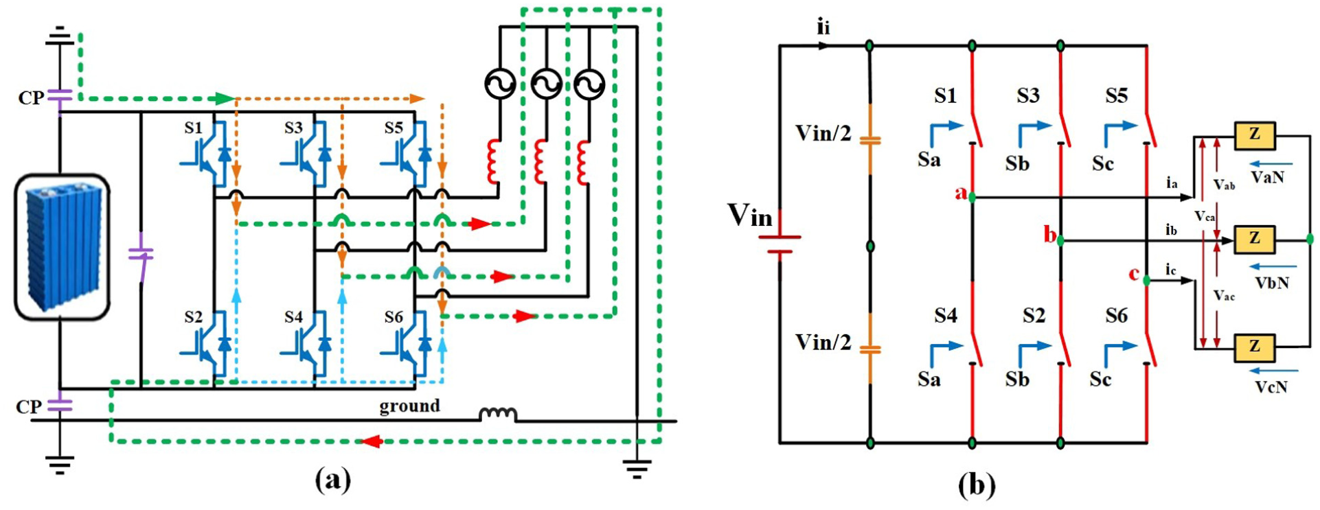
(a) The EV’s common-mode circuit for recharging or V2G modes and (b) three-phase inverter equivalent circuit.
A definition of

In equation (7),

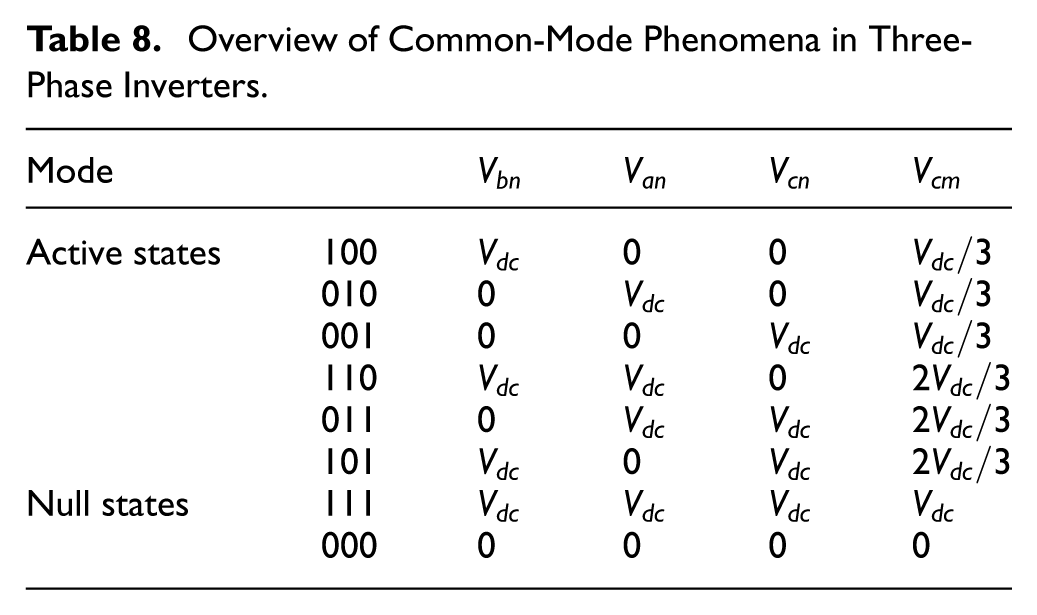
Equation (8)’s computation for standard mode voltage demonstrates that each collection of a three-phase inverter’s switching states corresponds to a particular value for the standard mode voltage. The list of standard mode voltages for all switching states is demonstrated in Table 8. Switches S1, S3, and S5 help reduce the voltage difference between the AC terminals and earth when operating in AC mode. This quick, balanced switching reduces current in the standard mode route by avoiding reverse currents that could cause leakage. Maintaining a balanced, steady AC voltage across the three terminals (loads) is facilitated by operating the switches S2, S4, and S6 in a specific order. It reduces leakage current in the CM path and imbalances in transient currents. This increases the system’s overall stability and reduces power losses from undesired leakage currents.
There are four levels to the standard mode voltage: 0,

In summary, lowering the CM voltage’s fluctuation range helps prevent leakage current in three-phase inverters. Even though various approaches were suggested to minimize the voltage of the standard mode, the bulk of them depended on modification techniques utilized by standard three-level NPC inverters.
Overview of Common-Mode Phenomena in Three-Phase Inverters.
Reconfiguration of the charging system to reduce the noise of the common mode
This section proposes reconfiguring the EV charging system to provide a consistent voltage in standard mode and minimize conduction losses.58–64 Below is a list of the orders in this section. First, the standard EV charging system structure is shown. Second, there are two ways to reconfigure the charging system: single-phase and three-phase reconfigurations. Concerning their distinct operating principles, the two methods are analyzed. The suggested charging topology and traditional systems are compared.11,12,35,38,58
Typical electric vehicle system structure
Figure 12(a) depicts a standard on-board plug-in electric vehicle charging system layout. It comprises the battery, charger, traction inverter, and DC/DC converter. Three modes for the EV may be distinguished based on power flow paths: V2G, charging, and traction. An arrow in Figure 12(a) indicates the direction of energy flow, such as the path between a battery and the grid or a battery and a motor. Common-mode routes are present when transferring power between a battery and the grid due to the grounded connection to the grid. Therefore, the noise of standard mode reduction during charging and V2G states is a primary focus for the suggested reconfiguration of EV charging systems. Moreover, in Figure 12(a), the DC bus capacitor helps reduce voltage fluctuations caused by sudden load changes during vehicle acceleration or when switching power between different operating modes, such as V2G and Traction Mode.11,12,35,38,58
(a) A typical plug-in on-board EV system structure, (b) proposed charging architecture for single-phase reconfiguration, and (c) the suggested single-phase reconfiguring charging architecture has charging or V2G modes.
Electric vehicle charging system reconfiguration for single-phase to charging system
Two alternative single-phase recharging topologies are proposed in this section. The first is seen in Figure 12(b). The single-phase charger with a switch (S1–S4) and the traction inverter and switches (S1–S6) make up a charging system. Two lines for the inverter and relays are linked to the charger and traction inverter outputs. Relays are turned off while the motor is driven solely by the traction inverter in traction mode. The charger is not functional in this instance. Conversely, a battery will be connected to the grid while the EVs are in V2G mode. These modes are depicted in Figure 12(c), where the AC-side relays are switched off, and the charger’s outputs are linked to the traction inverter’s two bottom switches (S4 and S6). The relay is open on the DC side, and the two switches (S4 and S6) linked in anti-series serve as the charger’s freewheeling.11,12,35,38,58
Figure 13(a) depicts the phase diagram for the second single-charging mechanism. The charger component is ignored in this reconfiguration technique and integrated with the traction inverter. To transport power between a battery and the grid, each of the six switches (S1–S6) in the traction inverter may operate as an inverter or a rectifier, depending on the mode of operation. In Figure 13(a), the charging circuit has been reconfigured using six switches (S1–S6) and six relays (R1–R6). Six relays (R1–R6)’ OFF and ON states control the converter’s operating modes. Specifically, a converter operates in traction mode for driving a motor, with (R1, R5, and R6) on and (R2, R3, and R4) off. As seen in Figure 13(b) and (c), the converter is a conventional two-level, three-phase inverter. Conversely, a converter operates in a charging or V2G state to provide electricity to the grid while (R1, R5, and R6) are OFF and (R2, R3, and R4) are ON. In this case, a converter is a single-phase inverter with energy transfer switches S1–S4 and series-linked freeing switches S5 and S6.11,12,35,38,58–64
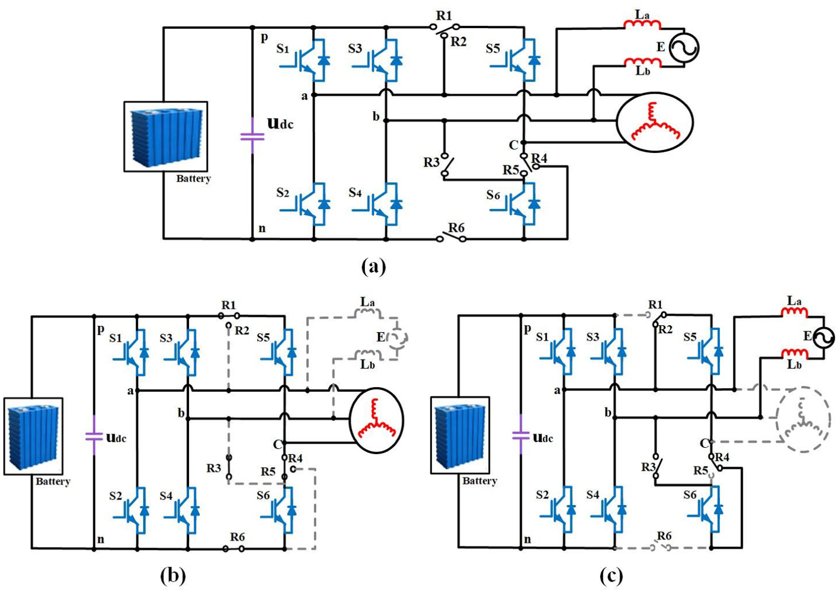
(a) Integrated single-phase reconfigurable charging topology, (b) mode of traction, and (c) charging mode or V2G mode.
The conversion of an EV charging system to a three-phase charging system
Furthermore, Figure 13(a) illustrates the reconfiguration process for a three-phase charging architecture. This mainly consists of the three-phase charger (S1’–S6’) and a traction inverter (S1–S6). Both converters are linked to a battery by the DC-to-DC converter, and on their left sides, they are connected in parallel.11,12,35,38,58–64 The grid and motor are linked to the right side of the two converters, respectively. Additionally, three relays attached to the output terminals for a phase leg of the two converters in a proposed reconfiguration system will be closed during charge or V2G state to reduce noise in standard mode. First, relays are turned off in traction mode. As seen in Figure 14(a), the charger is not operating in this mode; instead, a traction inverter runs independently to drive a motor.
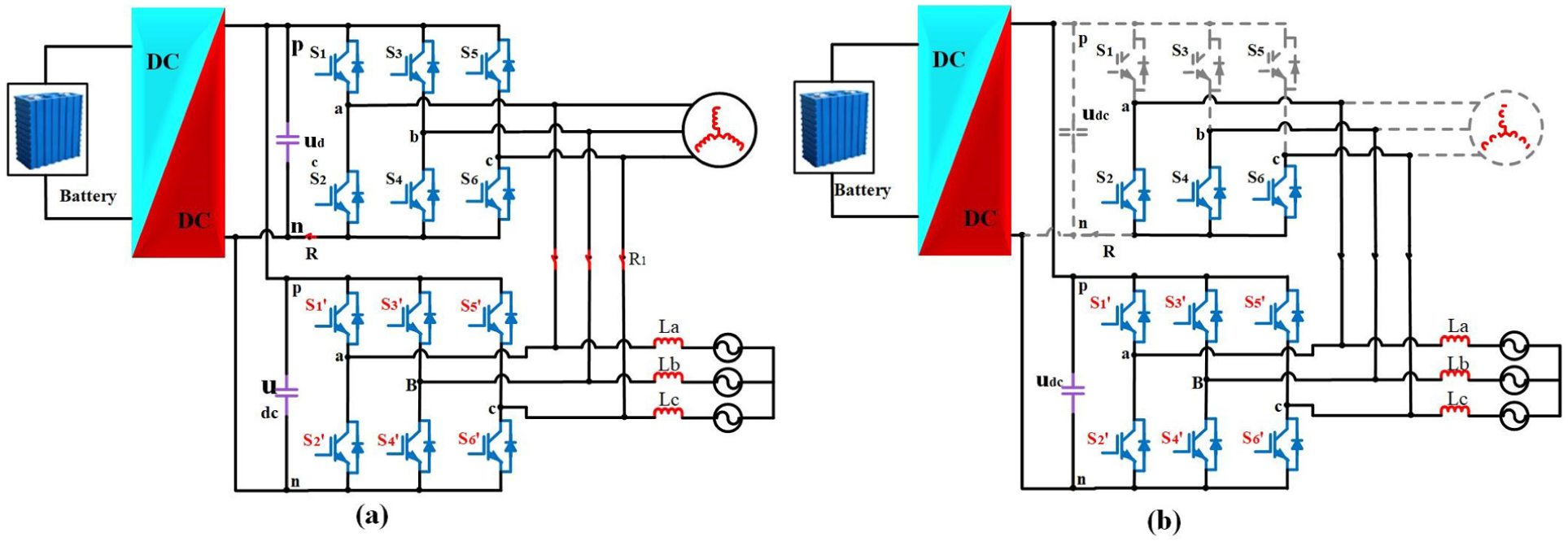
(a) Proposed charging topology for three phases of reconfiguration and (b) the suggested three-phase reconfiguration recharging topology includes charging or V2G modes.
Second, during a power transfer phase, a battery transfers energy to the grid through six switches for charging (S1’–S6’). At the same time, relays on the AC side are closed in the charge state, also known as the V2G state, as illustrated in Figure 14(b). To prevent the DC voltage from affecting the traction inverter, the relay on the traction inverter’s DC side is open. The charger’s six switches (S1’ through S6’) are off during freewheeling. All three lowest switches (S2, S4, and S6) for the traction inverter must be switched on during this time. The three wires and relays that link S2, S4, and S6 to the grid provide a freewheeling pathway for the converter. As a result, the charger’s output has three voltage levels, and the voltage in standard mode may be substantially decreased.
Multiplex charging system application in common mode noise reduction
The applications of multiplex charging systems in standard mode-based noise reduction are categorized into three areas: typical structure of an integrated EV charging system, application of three-phase charging mode for an integrated charging system, and an integrated single-phase charging system.11,12,35,38
Performance metrics of the charging process are synthesized from the integration of grid and infrastructure studies in Zhou and Preindl, 11 Khalid et al., 35 and Singh et al. 38 , and recent smart charging and V2G frameworks 29 (see Table 9). Besides, fast charging considerably reduces charging time but places greater stress on both the grid and the battery. Strategies for V2G and smart charging enhance system efficiency and reduce peak load, as supported by Lei et al. 29 and Khalid et al. 35 The performance enhancements for system-level are based on optimization and the impact of grid studies in references.14,15,29–31,35
Metrics of EV-renewable integration/grid.
Typical structure of an electric vehicle integrated charging system
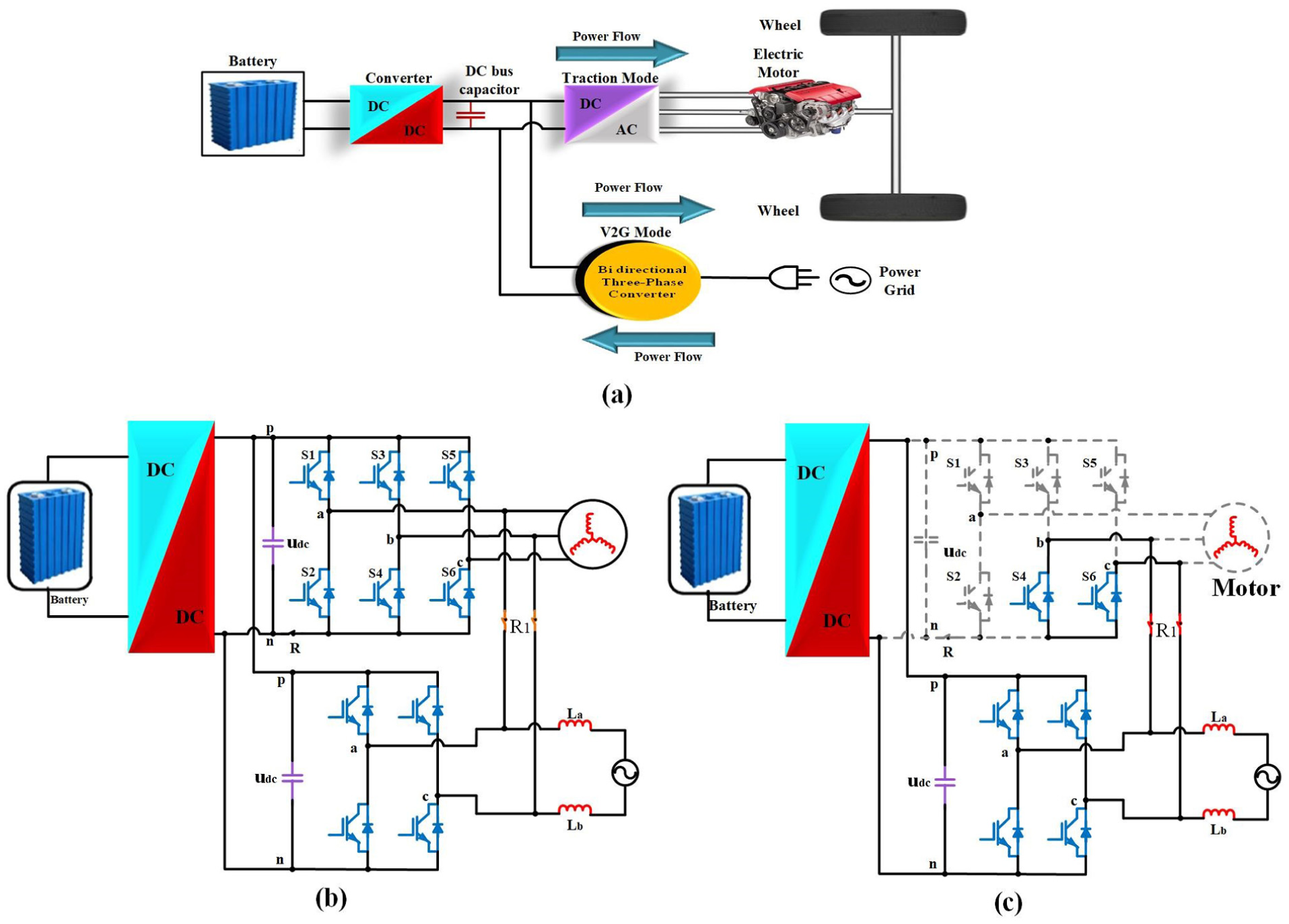
Figure 15(a) presents a conventional layout for an on-board integrated plug-in electric vehicle technique used for rear-wheel drive. The system consists of the motor, DC/DC converter, battery, and bi-directional converter.12,96 While a vehicle is in traction mode, a bidirectional converter acts as an inverter to power the rear-wheel motor. A bi-directional converter functions as the rectifier in charging mode, sending electricity from the grid to a battery. Additionally, electricity may go from the battery to the grid if the EV has V2G service. The arrows in the diagram indicate the power flow pathways. As shown in Figure 15(b), the system’s operating modes may be split into a charging state and a V2G/traction state based on the direction of the power flow. 12 Besides, the DC bus capacitors in Figure 15(a) contribute to maintaining the stability of the voltage on the DC lines, ensuring smooth operation of the motor, and reducing fluctuations during switching between different modes (charging, propulsion, V2G). However, the DC bus capacitor in Figure 15(b) stabilizes the DC distributed to both the front and rear motors, ensuring consistent power delivery and preventing fluctuations that could affect performance.
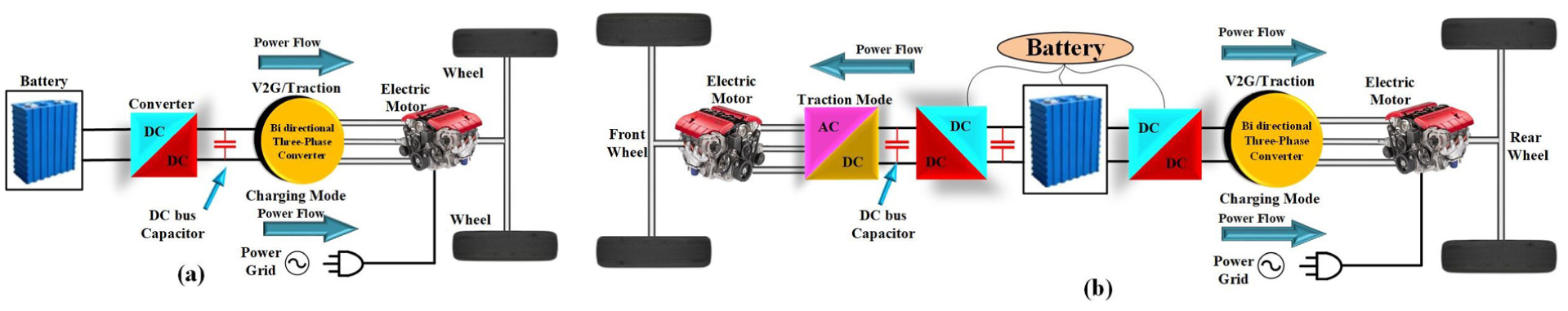
(a) Structure typical of an on-board integrated plug-in EV system with rear-wheel drive and (b) structure typical of an on-board integrated plug-in electric vehicle.
Integrated charging system proposed for three-phase charging mode application
The proposed topology, shown in Figure 16(a), consists of two sets of paralleled three-phase converters as its primary components. Both converters are linked to a battery by the DC-to-DC converter, and their left sides are connected in parallel. A front-wheel motor and a rear-wheel motor are attached to the right side of the two converters, respectively. In the proposed system, three relays close during charge, or V2G state, to reduce noise in standard mode and are linked to the phase-leg outputs of the two converters. The operating tenets of the suggested charging topology in various operation modes are listed.11,12,96
Mode 1: Relays are not linked while the system is in traction mode. As shown in Figure 16(a), each of the two converters operates independently to power its respective motor.
Mode 2: Relays
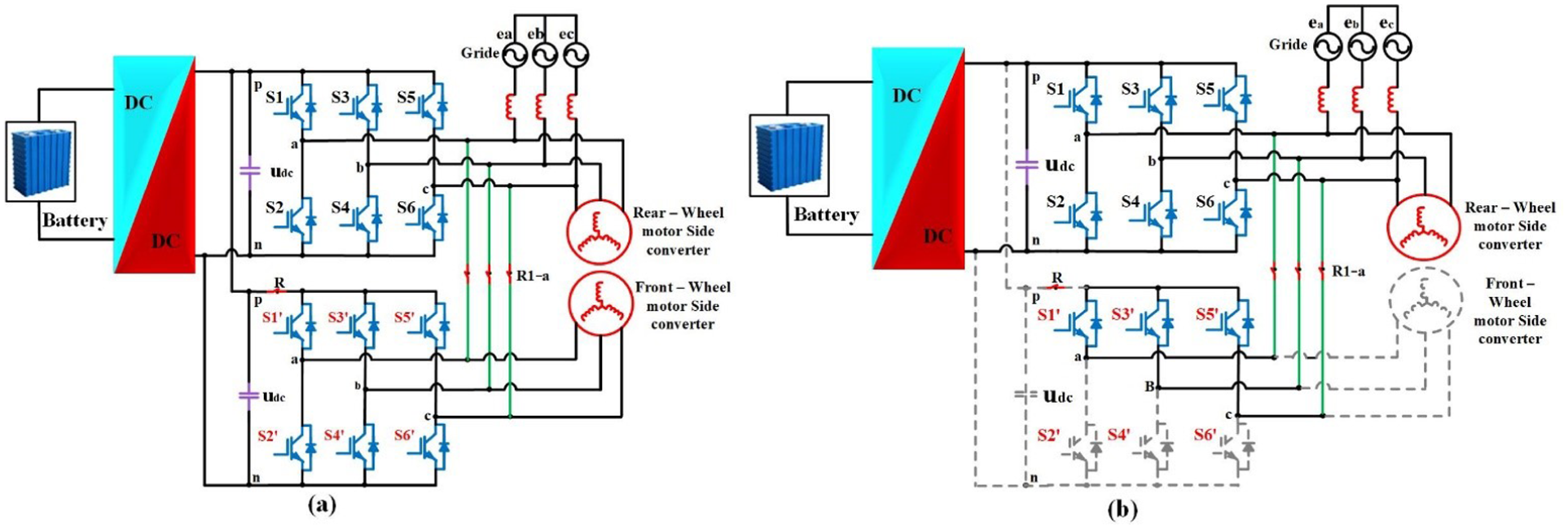
(a) Four-wheel drive integrated three-phase charging architecture proposed and (b) an integral three-phase charge design with a four-wheel drive is recommended for charge or V2G mode.
The suggested single-phase integrated charging system
In addition, Figure 17(a) shows a new charging method for the front-wheel motor converter that uses anti-series-connected switches for a single-phase charging state or a V2G state with a single-phase grid to reduce noise in standard mode without adding additional equipment costs.11,12,58–64 The two 3-phase converters’ phase A and phase B outputs are linked by two relays and lines in Figure 17(a).
Mode 1: The relays
Mode 2: The rear wheel may be connected to a single-phase grid via bridges A and B during charging or V2G states, as shown in Figure 17(b). Only S1 and S4 of the rear-wheel converter are functional. Additionally, due to the connection for relays
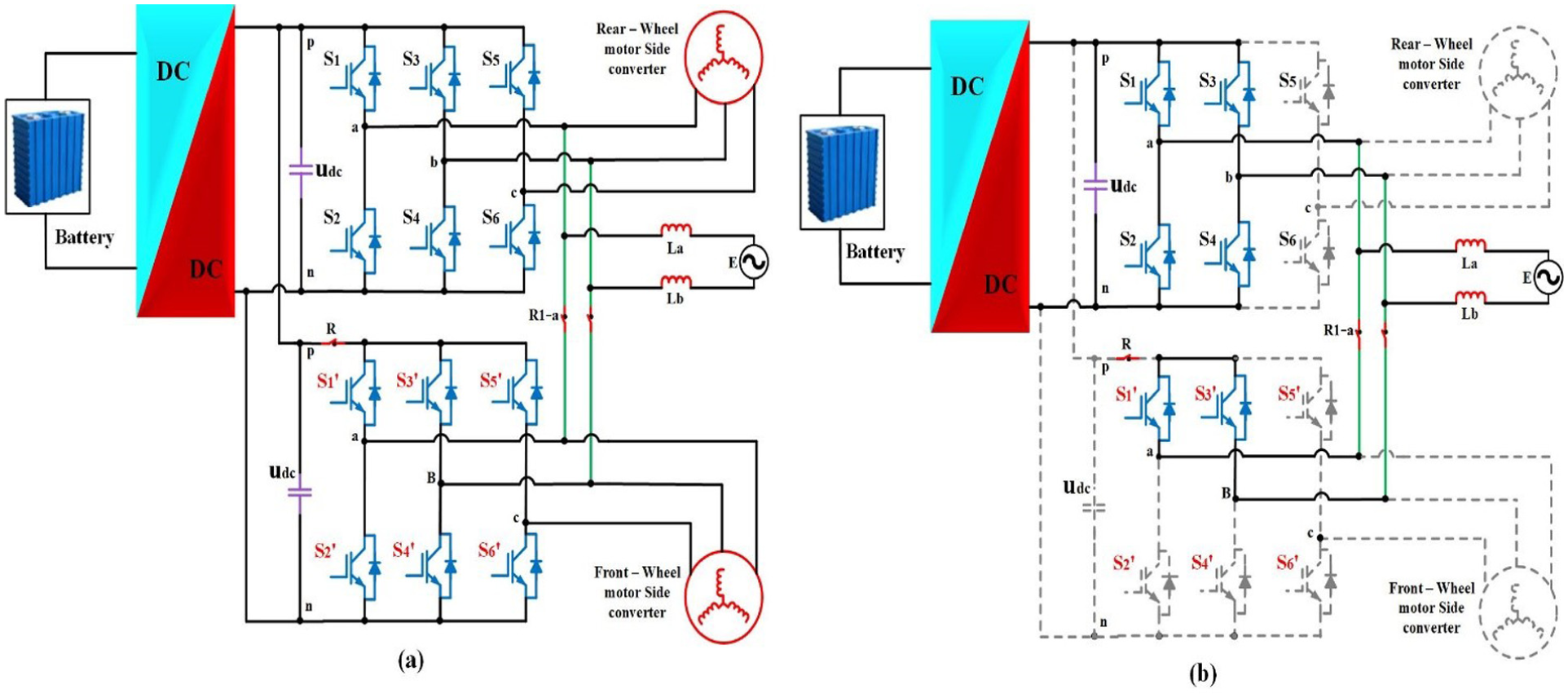
(a) A four-wheel drive integrated with a single-phase charging architecture is proposed and (b) a four-wheel drive integrated with a single-phase charging scheme is recommended for charging or V2G modes.
Practical and policy implications
a. Encouragement of EV implementation through subsidies and incentives:
Implication: Governments could introduce taxes or subsidies to encourage the development of EVs for a wide range of users and consumers. Please consider the discussions on batteries and their high cost, as well as the charging infrastructure; financial incentives can help lower initial costs and increase EV adoption.
Recommendation of policy: Increase motivation by purchasing partial refunds, decreasing registration fees, and crediting taxes for EVs. Furthermore, policies might help subsidize battery recycling to reduce the impact of environmental and battery costs over time.
b. Growth of a robust infrastructure of charging:
Implication: With the increasing adoption of EVs, there is a critical need to investigate charging networks that satisfy various types of EVs and regions, mainly in underserved and rural areas. Results indicate that partial access to station charging remains an important issue.
Recommendation of policy: Governments should direct the increase of nationwide infrastructure charging, with a highlight for rural extension. It helps to investigate more public charging stations, with particular goals for renewable-based charging stations and high-speed charging in isolated areas.
c. Standards for production of battery, disposal, and safety:
Implication: The review presents the significance of production for sustainable batteries and clearance due to environmental impact and high production costs for innovative batteries. Founding disposal standards and safety measures may reduce the long-term environmental impacts.
Recommendation of policy: Implement severe standards for the production of batteries, containing requests for utilizing sustainable materials and safe practices. Adjusting policies may require initiatives to promote battery recycling.
d. Incentives for integration of renewable energy in charging:
Implication: The integration of source-based renewable energy into the charging infrastructure could decrease the carbon footprint related to the charging of EVs.
Recommendation of policy: Improve incentives for integrating the charging infrastructure.
e. Provision for emerging technologies for charging:
Implication: With fast charging and wireless developments, supportive structures can inspire commercial deployment and innovation.
Recommendation of policy: Present funding and grants for development and research in modern charging technologies such as bidirectional charging and wireless.
Conclusions
This paper provides an overview of the many types of EVs, the technology employed, and the advantages of EVs. The complete taxonomy of EVs, which includes BEVs and PHEVs, is discussed. Batteries are an essential consideration for EVs, as they affect the vehicle’s autonomy. This review examines several types of batteries based on these features. Batteries for EV applications rely on short- and long-term energy storage systems. It also examined the current state of electric vehicle technologies, including HEV, PHEV, BEV, and FCEV, and their power electronics and power conversion components. The EV charging criteria have shown various on-board and off-board battery chargers. Integrated on-board chargers allow for optimal utilization of traction and propulsion converters for power and motor windings. Still, it takes a long time to fully recharge electric vehicle batteries. Off-board chargers are high-power chargers that take a few minutes to recharge EV batteries to 80% state of charge (SOC). A review of front-end and back-end converter typologies is provided, including the properties of front-end converters with PFC for electric vehicle battery charging. In addition, there is a detailed DC/DC converter configuration. The charging typologies with integrated chargers, front-end (AC–AC), and back-end (AC–DC) converters are shown. In addition, it presents a reconfiguration notion and a multiplex application of integrated electric vehicle charging systems to reduce the device cost of the entire circuit. The new topologies use the traction inverter’s inherent switches to produce additional freewheeling channels during charging mode, reducing common-mode noise. Without the isolating transformer, the system’s weight and volume are significantly reduced, and conduction loss and device cost are minimal. In addition, it presents a reconfiguration notion and a multiplex application of integrated electric vehicle charging systems to reduce the device cost of the entire circuit. The new topologies use the traction inverter’s inherent switches to produce additional freewheeling channels during charging mode, reducing common-mode noise. Without isolating the transformer, the system’s weight and volume are significantly reduced, and conduction loss and device cost are minimal. Key findings from the review include:
A detailed taxonomy of EVs, including battery electric vehicles (BEVs), plug-in hybrid electric vehicles (PHEVs), and fuel cell electric vehicles (FCEVs).
Battery technologies are essential in short- and long-term energy storage systems, impacting vehicle autonomy and efficiency.
A review of current EV power systems, including power electronics, power conversion systems, and charging technologies.
On-board and off-board charging systems, comparing their efficiency, charging times, and practical applications.
The advantages of integrated on-board chargers include the efficient use of traction and propulsion converters, though they require longer charging times.
The role of off-board chargers in achieving faster recharging times, with the ability to charge EVs to 80% state of charge (SOC) in a few minutes.
A review of front-end and back-end converter typologies, including power factor correction (PFC) for improved battery charging.
New converter topologies and reconfiguration methods that reduce device costs, system weight, and volume while minimizing conduction losses.
Footnotes
Appendix
Handling Editor: Lin He
Funding
The authors received no financial support for the research, authorship, and/or publication of this article.
Declaration of conflicting interests
The authors declared no potential conflicts of interest with respect to the research, authorship, and/or publication of this article.