
Abstract
Gangway is an equipment used to transport personnel and cargo between floating structures and platforms. It finds extensive applications in maritime rescue, offshore wind power operation, and offshore oil development. However, the design of gangways is a complex multidisciplinary challenge that integrates mechanical, electronic information, and control technologies. This paper reviews recent progress in mechanical structural design, system modeling techniques, control systems, and explores future possibilities such as applying birds’ head stability mechanisms to enhance the stability of gangway. The initial sections examine existing gangways, summarizing their structural types, manufacturing materials, and structural analysis methods. Subsequently, detailed discussions cover system modeling approaches, including wave modeling, ship modeling, and gangway modeling. Next, the control system is addressed, encompassing detection units, control units, and actuators. Finally, the study highlights the head stability control observed in birds or insects, which closely parallels the control requirements for gangways.
Introduction
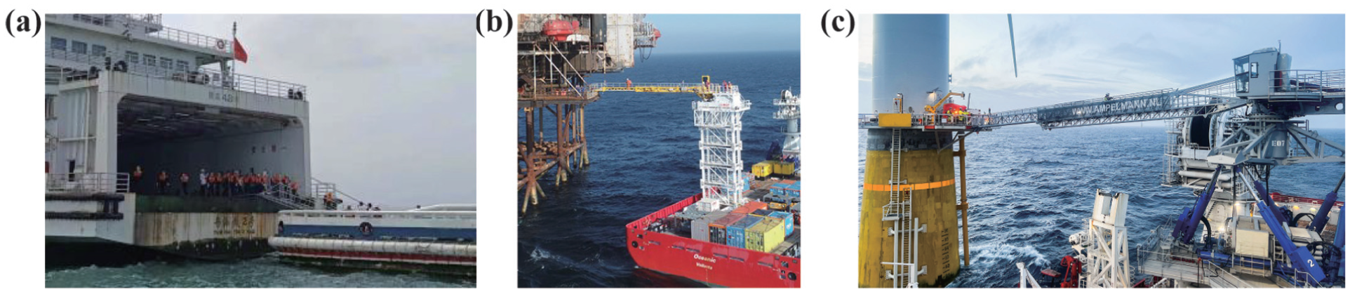
The gangway constitutes a critical piece of engineering equipment primarily used for the transportation of personnel and cargo. It can be installed on a variety of offshore engineering vessels, including wind power Service Operation Vessels (SOVs), offshore support vessels, offshore transport vessels, and pilot boats, thereby facilitating the transfer of personnel or cargo between two floating structures or between floating platforms and offshore installation.1,2 As a continuous transport apparatus, the gangway offers considerable advantages over conventional transfer methods, such as helicopter or gondola transfers, including reduced economic costs, enhanced personnel transfer efficiency, and reliable, safe passage. This equipment is particularly well-suited for establishing rapid evacuation routes between two military vessels or between rescue vessels and vessels in distress. Additionally, it is highly effective for creating passageways between wind power SOVs and wind power towers, as well as between oil drilling SOVs and drilling platforms. Consequently, gangways have extensive applications across maritime rescue operations, offshore wind power maintenance, offshore oil and gas development, and military sectors. Figure 1 illustrates the various application scenarios of gangways across these fields.
However, the marine environment is complicated and dynamic. During the process of connecting the gangway to the target and moving individuals or cargo to the target, the mother ship on which the gangway is placed unavoidably undergoes movements in various directions owing to wind or waves. As seen in Figure 2, the mother ship moves in six degrees of freedom: surge, sway, heave, roll, pitch, and yaw. These vibrations may cause the gangway to detach from the target or to undergo extreme motion in multiple directions. To successfully connect to the target and ensure the safety of personnel passage or cargo transportation, the gangway must have high-precision motion-compensated functionality that allows it to accurately control its attitude and mitigate the effects of unpredictable factors such as wind and waves. This motion-compensated functionality can also increase the speed, stability, and safety of maritime operations. 6 Motion-compensated functionality is implemented by the cooperation of ship motion state detection, control algorithms, and motion-compensated actuators. Consequently, the design of gangways transcends a straightforward mechanical engineering challenge, representing a complex multidisciplinary problem that integrates mechanical engineering, electronic information systems, and control technologies. This area encompasses novel theories, methodologies, materials, and processes, and has emerged as a prominent focus of contemporary research.
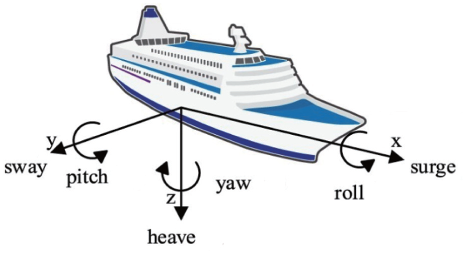
The movement of the mother ship in six degrees of freedom. 7
In recent years, both industry practitioners and academic researchers have undertaken comprehensive investigations into the mechanical design, 8 system modeling, 9 and control strategies of gangways, 10 resulting in the development of various types of these structures. Diverse methodologies have been applied to formulate the kinematic and dynamic models of gangways, alongside evaluations of control system performance under different algorithmic approaches. 11 Several scholars have also conducted review studies on this subject. García et al. 12 reviewed the main options of access systems available in the market and broadly classified them into three categories: active, semi-passive and passive system. Ma and Zhang 13 introduced the different types of access gangway system with different motion compensation techniques, crane systems for offshore access and hydraulic clamping system on ships. Zhang 14 reviewed the development history and technological progress of gangways, analyzed the main commercially available access systems, and discussed the key technologies of offshore wind turbine gangways. Hu and Yung15,16 provided an overview of three ways to access an offshore wind turbine and emphatically discussed commercially available and prototyped motion compensated gangway systems. Twigt analyzed and compared conventional and walk-to-work transfer methods used in the offshore wind industry in terms of accessibility, efficiency and individual risk to the transferee. 17
Although numerous reviews have addressed offshore gangways, there remains a notable deficiency in comprehensive analyses focusing on the design methodologies or technologies associated with gangways. Therefore, this review aimed to provide a comprehensive review of the current state of research, technical challenges, and prospective developments concerning the mechanical design, system modeling, and control strategies of gangways. Furthermore, it examines the potential application of insights derived from birds’ or insects’ head stability studies to inform and enhance the development of gangway systems. Compared with existing review articles, the novelty of this paper lies in the following:
It provides a comprehensive overview of existing commercial gangway products, classifies them appropriately according to their structural form, and identifies future development directions for gangways in terms of structural design, material selection and structural analysis.
It provides a comprehensive analysis of the current state of modeling for wave, mother ship and gangway, elucidating their intrinsic relationship with and necessity for gangway design, and offering a clear modeling approach for motion compensation control of gangways.
A comprehensive review of the composition, accuracy and existing issues regarding the detection, control and actuation of gangway control systems has been conducted, and recommendations have been provided to improve control performance and reduce energy consumption.
The potential of biomimetic design (such as the stability mechanisms of bird head) to inspire innovative gangway structures and control systems has been explored, offering new approaches for further optimizing structural design and enhancing control performance.
The remainder of this article is organized as follows. Section “Research methodology” outlines the literature search methodology and selection criteria. Section “Mechanical structure” discusses the structural form, material selection, and structural analyze of gangways, all of which are intimately related to the mechanical structure design. Section “System modeling” offers a modeling framework for motion compensation of gangway and some feasible experimental verification methods. Section “Control system” analyzes existing monitoring, control, and execution units, and discusses future development directions for improving control performance and reducing energy consumption. Section “Other design methods” discusses some inspirations from birds’ head stability in gangway innovation. Section “Conclusion” concludes the paper and discusses potential avenues for future research.
Research methodology
In order to comprehensively retrieve literature relevant to the gangway system which involves multiple disciplines, the entire gangway system was first divided into an overall component and several constituent parts. Consequently, the search topics were categorized into “gangway,”“mechanical structures,”“modeling methods,”“control systems,” and “other techniques,” as shown in Figure 3. There were no specific restrictions on the time span of the search. The specific search methods for each topic are as follows:
For the “gangway” topic, searches were conducted in databases such as Google Scholar, Web of Science, and CNKI using keywords including “gangway,”“offshore access system,”“turbine access system,” and “telescopic access bridge,” and only literature closely related to gangways was selected.
For the “mechanical structures” topic, the primary databases used were Google Scholar, Web of Science, and CNKI. Considering that existing commercial gangways are primarily marketed as products, search results from the Microsoft Bing search engine were also included. The search keywords included any one of “gangway,”“offshore access system,”“turbine access system,” or “telescopic access bridge,” along with supplementary keywords such as “materials” and “strength.”
For the search on topics such as “modeling methods,”“control systems,” and “other techniques,” considering that the literature primarily consists of peer-reviewed articles, the search scope was limited to Google Scholar, Web of Science, and CNKI. The search terms included any one of “gangway,”“offshore access system,”“turbine access system,” or “telescopic access bridge,” along with one of the corresponding topics, such as “model,”“ship motion,”“control,” or “algorithm.” In addition, targeted searches were conducted on the references cited in the retrieved literature to expand the search results. In the search for the “other methods” topic, “head stabilization” was used as a keyword, because the head stabilization of birds shares similarities with the stability control of gangways, thereby expanding the design concepts for gangways.
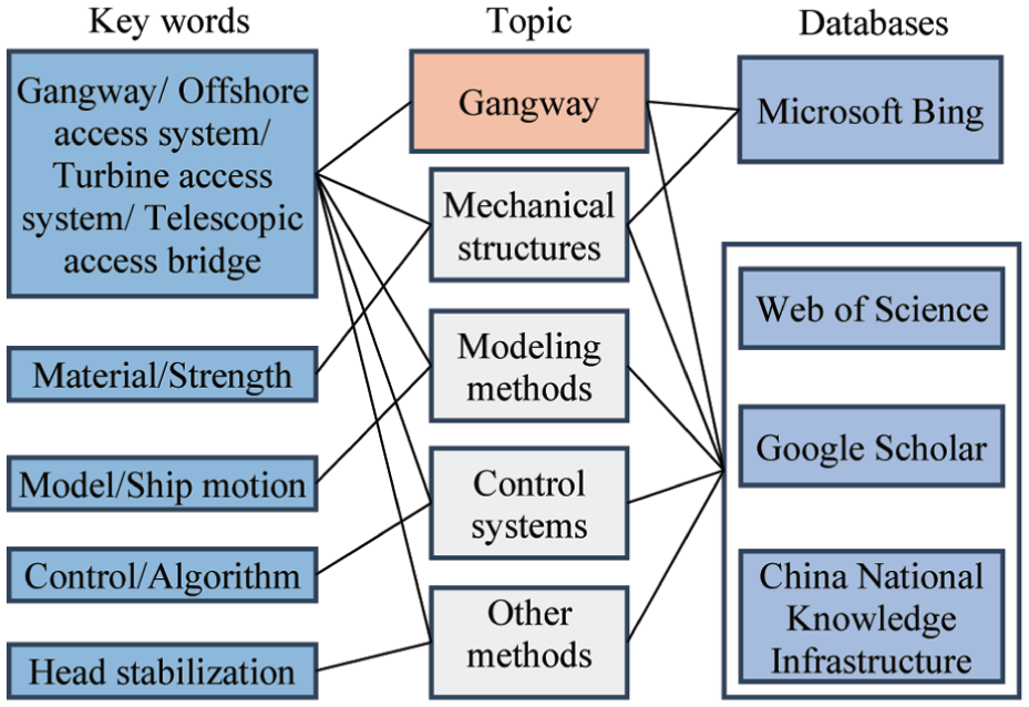
Literature research methodology.
Mechanical structure
The mechanical structure of the gangway serves as the foundation for the transfer of personnel and cargo, and it functions similarly to an intelligent organism’s skeleton and muscles. If the mechanical structure is not designed properly, it is difficult to achieve the motion-compensated function even if the control system is as powerful as an intelligent organism’s brain. Therefore, this section focuses on study into the structural form, material selection, and structural analyze of gangways, all of which are intimately related to the mechanical structure design.
Structural form
A gangway consists of three parts: a gangway body, a motion-compensated mechanism, and an installation base. Among these, the gangway body acts as a passageway for personnel and cargo, and it is often made up of a fixed and a telescoping body. Whether it’s a fixed or telescopic body, its fundamental framework is a truss. This is due to the fact that a truss is a planar or spatial structure made up of straight rod-based triangular units. And the straight rods of a truss sustain axial tensile or compressive forces during operation, which can fully utilize the material strength. In situations of longer spans, this design can conserve materials, reduce self-weight, and boost rigidity when compared to solid beams. The motion-compensated mechanism is an executive device that keeps the gangway body or landing point in a static position relative to the target platform. Its primary objective is to counteract the movements of the gangway induced by ship motions resulting from environmental factors such as wind and waves. This capability facilitates applications in offshore wind power maintenance, offshore oil and gas operations, and other complex marine environments. By mitigating the effects of adverse sea conditions, the mechanism extends the operational window and reduces the risk of personnel or cargo accidents caused by ship collisions or inertial forces during transfer procedures. The installation base acts as the interface connecting the gangway to the vessel. It is securely affixed to the deck of the host ship and is engineered to withstand both static and dynamic loads imposed on the gangway, including wave impacts and inertial forces encountered during personnel transfer activities.
Although existing gangways varied in form, the fundamental structural difference is the sort of motion-compensated mechanism. To better understand the structure of the existing gangway, the gangways will be classified based on the type of motion-compensated mechanism. That is, serial and parallel motion-compensated systems. A serial motion-compensated system is made up of a series of single-degree-of-freedom basic units, with each unit’s output serving as the input for the next. The principal function of this system is to preserve relative static alignment between the landing point and the target platform. As shown in Figure 4(a) to (c), point A is the landing point. When the mother ship for installing the gangway is stationary, its end point is located at point A. When the mother ship is affected by waves and deviates from its stationary position, its end point will undergo a motion M1, shifting from point A to point A’. In order to keep the end point of the gangway stationary relative to the landing point A, the actuators E1, E2, and E3 of the serial motion-compensation mechanism perform a telescopic motion, causing the end point of the gangway to return from point A’ to point A through the compensation motion M’1. This approach offers benefits including a compact deck footprint and simplified control; however, it is characterized by relatively low stiffness. Conversely, a parallel motion-compensated system comprises multiple independent components arranged in parallel, typically including a fixed platform, a movable platform, and several parallel branches linking the two. The Stewart platform is the most prevalent example, wherein the fixed platform is rigidly mounted on the deck. The objective of this system is to maintain the relative inertial stability of the movable platform, thereby ensuring that the gangway body remains stationary with respect to the Earth. As shown in Figure 4(d) to (f), when the mother ship installing the gangway is stationary, the movable platform is stationary in a neutral position, and the end point of the gangway coincides with the boarding point A. When the mother ship is affected by waves and deviates from its stationary position, the movable platform will generate a movement M1, which not only shifts its center position but also causes it to deflect, resulting in the end point of the gangway shifting from point A to point A’. To keep the movable platform in a neutral position, the execution units E1, E2, E3, E4, E5, and E6 of the parallel compensation mechanism need to perform telescopic movements, causing the movable platform to generate a compensation movement M’1 and return to the neutral position. When the movable platform returns to the neutral position, the end point also returns to the boarding point. Therefore, the compensation objective of a serial gangway is to keep the end point at the boarding point, while the compensation objective of a parallel gangway is to keep the movable platform in a neutral position. The parallel motion-compensated system is advantageous due to its high load-bearing capacity, elevated stiffness, and structural stability, although it requires a comparatively large deck area.
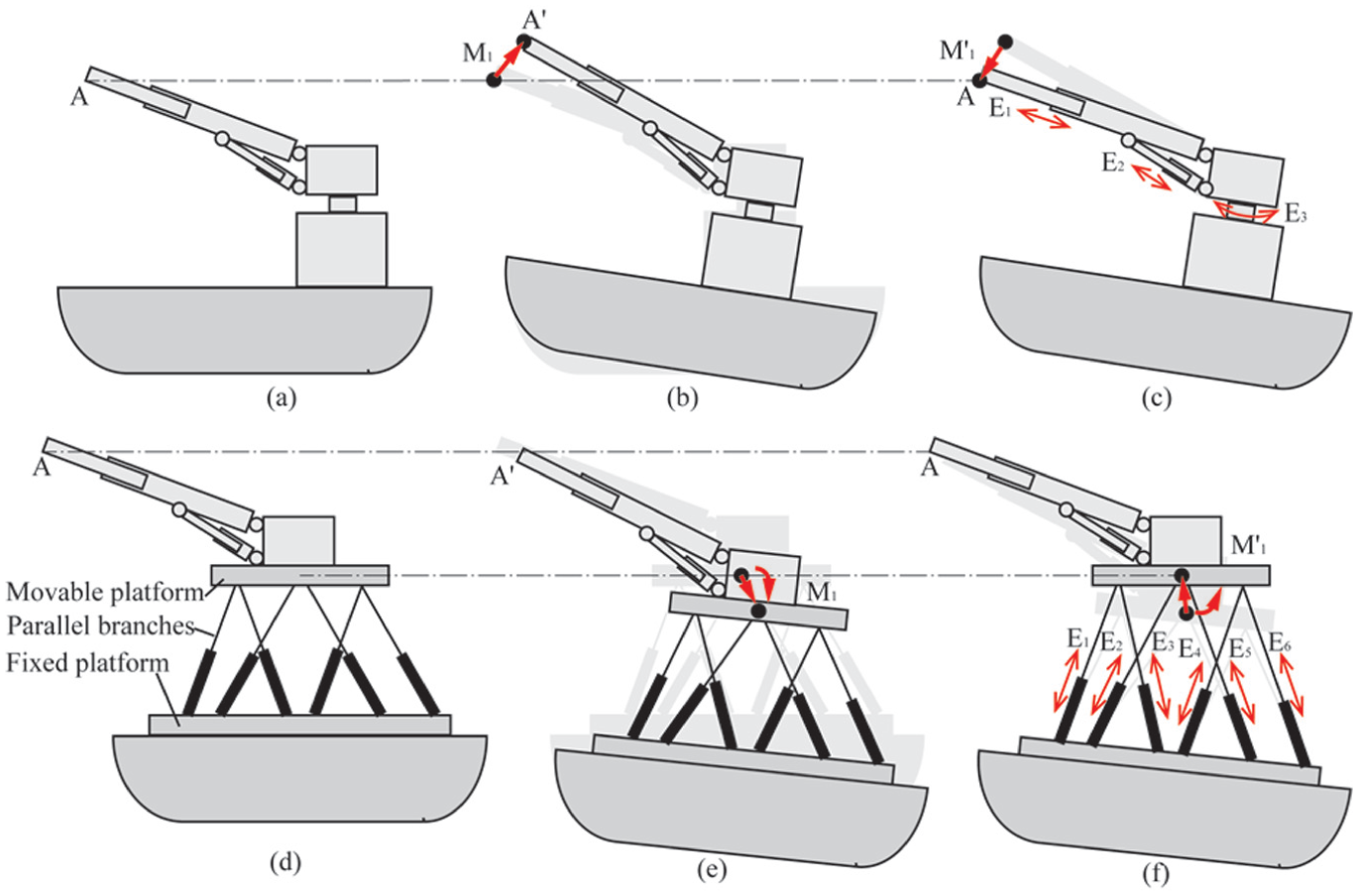
Motion compensation process of the serial and parallel gangway: (a) the mothership remains stationary while the endpoint is positioned at point A, (b) the mothership deviates from its stationary position, causing the endpoint to shift from point A to point A’, (c) the endpoint returns from point A’ back to point A, (d) both the mothership and the movable platform are stationary, with the platform in a neutral position, (e) the mothership deviates from its stationary position, prompting the movable platform to produce a movement denoted as M1, and (f) the movable platform executes a compensatory movement, labeled M1’, returning to the neutral position.
To enhance both the ease of installation and the motion compensation capabilities of gangways, numerous manufacturers have undertaken extensive improvements beyond the conventional serial and parallel motion-compensated gangway designs, resulting in a greater variety of gangway types. Consequently, a primary-level classification system proves insufficient to address these developments. Thus, existing gangways are further categorized based on their degrees of freedom and installation characteristics. Specifically, serial motion-compensated gangways are subdivided into five types: (1) three-degree-of-freedom gangways with fixed bases (hereinafter referred to as S1 gangways), (2) three-degree-of-freedom gangways with modular bases (hereinafter referred to as S2 gangways), (3) four-degree-of-freedom gangways with fixed bases (hereinafter referred to as S3 gangways), (4) four-degree-of-freedom gangways equipped with roll compensation bases (hereinafter referred to as S4 gangways), and (5) four-degree-of-freedom gangways featuring height-adjustable bases (hereinafter referred to as S5 gangways). In contrast, most parallel motion-compensated gangways employ the Stewart platform for motion compensation and exhibit minimal variation; therefore, they are collectively classified under a single category, namely parallel motion-compensated gangways (hereinafter referred to as P gangways). The classification framework for existing gangways is illustrated in Figure 5.
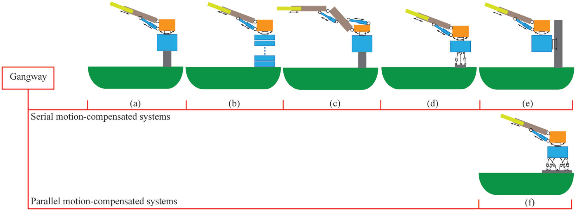
Categorization of existing gangways: (a) three-degree-of-freedom gangways with fixed bases, (b) three-degree-of-freedom gangways with modular bases, (c) four-degree-of-freedom gangways with fixed bases, (d) four-degree-of-freedom gangways equipped with roll compensation bases, (e) four-degree-of-freedom gangways featuring height-adjustable bases, and (f) parallel motion-compensated gangway.
Three-degree-of-freedom gangways with fixed bases
This type of gangways predominantly comprises products manufactured by Barge Master Company, Kenz Figee Group, SMST Company, Z-Bridge Company, Uptime Company, Guangzhou Shipbuilding and Marine Engineering Design Institute (hereinafter referred to as GSI), China State Shipbuilding Corporation South China Ship Machinery Co. (hereinafter referred to as SCSM), Ltd., Shanghai Zhenhua Heavy Industry Co., Ltd. (hereinafter referred to as Zhenhua), and other enterprises, as illustrated in Figure 6. Their structural configuration is illustrated in Figure 5(a) and representative products’ parameters are shown in Table 1. A key characteristic of this type is that the base height is fixed and must be predetermined according to the specific work object and the installation vessel prior to deployment. Due to the inability to adjust the height, these gangways are unsuitable for boarding operations involving vessels with substantially varying heights during practical use.
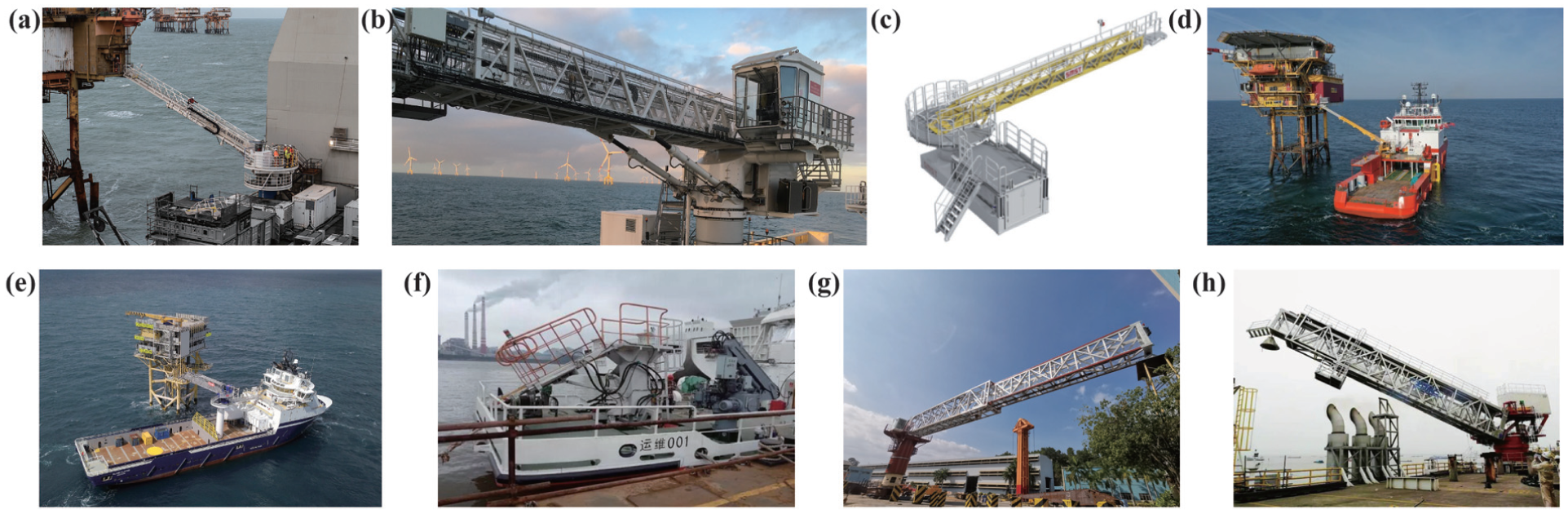
Products of three-degree-of-freedom gangways with fixed bases: (a) Barge Master’s gangway installed on a fixed pedestal 18 , (b) Kenz Figee group’s 3D active motion compensated gangway 19 , (c) SMST’s gangway (also called telescopic access bridges) on a fixed pedestal 4 , (d) Z-Bridge’s bring-to-work system 20 , (e) uptime’s 23.4 m 21 , (f) China’s first active motion compensated gangway made by Guangzhou Shipbuilding and Marine Engineering Design Institute 22 , (g) offshore gangway developed by China State Shipbuilding Corporation South China Ship Machinery Co., Ltd. 23 , and (h) motion-compensated gangway developed by Shanghai Zhenhua Heavy Industry Co., Ltd. 24
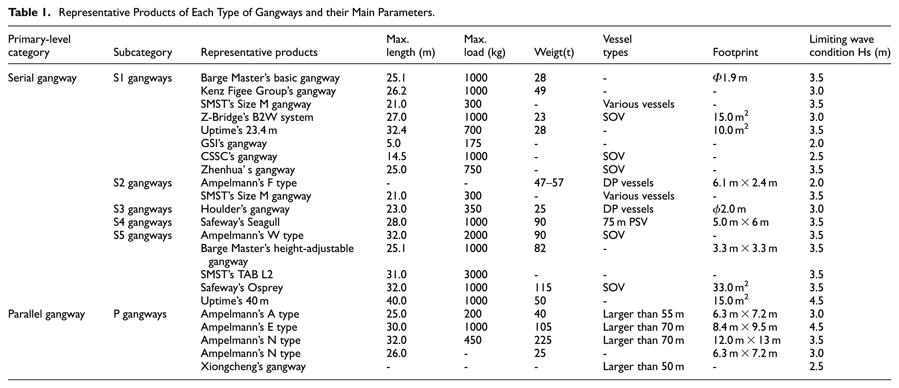
Representative Products of Each Type of Gangways and their Main Parameters.
Three-degree-of-freedom gangways with modular bases
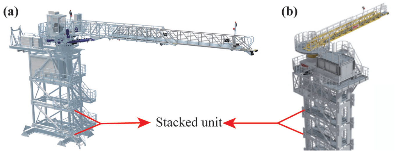
The products categorized within this class of gangways primarily include the F-type gangway, which is produced by Ampelmann Company, as well as the telescopic access bridge composed of modular elements, manufactured by SMST Company. The CAD-drawing of these products is shown in Figure 7. The structural configuration of this type of gangways is illustrated Figure 5(b). A key characteristic of this design is that the base consists of modular stacked units. The base height can be modified by adding or removing these stacked modules, enabling straightforward adaptation for objects positioned at varying heights and for diverse types of installation vessels. Consequently, this design offers greater flexibility in installation and deployment compared to the first category of gangways.
Four-degree-of-freedom gangways with fixed bases
This category of gangways predominantly encompasses the serial motion-compensated gangway manufactured by Houlder Company. The CAD model of this device is illustrated in Figure 8, while its structural schematic is presented in Figure 5(c). By incorporating an additional degree of freedom into the motion-compensated mechanism, the system is capable of compensating for heave motion across an expanded range. Consequently, even when the heave motion of the installation vessel exhibits substantial variability, personnel can traverse the gangway at a reduced incline angle.
The serial motion-compensated gangway manufactured by Houlder. 26
Four-degree-of-freedom gangways equipped with roll compensation bases
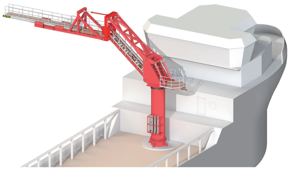
This category of gangways predominantly encompasses the Seagull type gangway manufactured by Safeway Company. The physical picture of this gangway is shown in Figure 9 and its structural configuration is illustrated in Figure 5(d). It can be represented an enhancement achieved by integrating a roll motion-compensated actuator into a three-degree-of-freedom gangway with a fixed base. This modification facilitates improved compensation for roll motion, thereby allowing personnel to traverse the gangway with minimal lateral displacement, even under conditions of substantial roll motion of the host vessel.
The physical picture of seagull type gangway manufactured by Safeway Company. 27
Four-degree-of-freedom gangways featuring height-adjustable bases
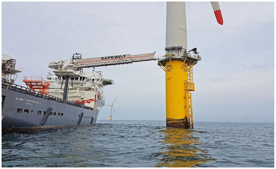
This category of products encompasses the W-type gangway produced by Ampelmann Company, the gangway featuring an integrated elevator within a height-adjustable base developed by Barge Master Company, the height-adjustable base gangway from SMST Company, the Safeway Osprey by Safeway Company, the Uptime 40 m from Uptime Company, as well as offerings from other manufacturers. A physical representation or CAD model of these gangways are presented in Figure 10, while their structural schematic is illustrated in Figure 5(e). The capability for direct adjustment of the base height enables these gangways to accommodate variations in landing height or tidal fluctuations across a wide range. In comparison to the first four types of gangways, this design demonstrates greater versatility and holds more promising potential for application as a large-scale gangway system.
Products of four-degree-of-freedom gangways featuring height-adjustable bases: (a) the W-type gangway produced by Ampelmann Company 28 , (b) the gangway featuring an integrated elevator within a height-adjustable base developed by Barge Master Company 18 , (c) the height-adjustable base gangway developed by SMST Company 4 , (d) the Safeway osprey developed by Safeway Company 29 , and (e) the uptime 40 m developed by Uptime Company. 30
Parallel motion-compensated gangways
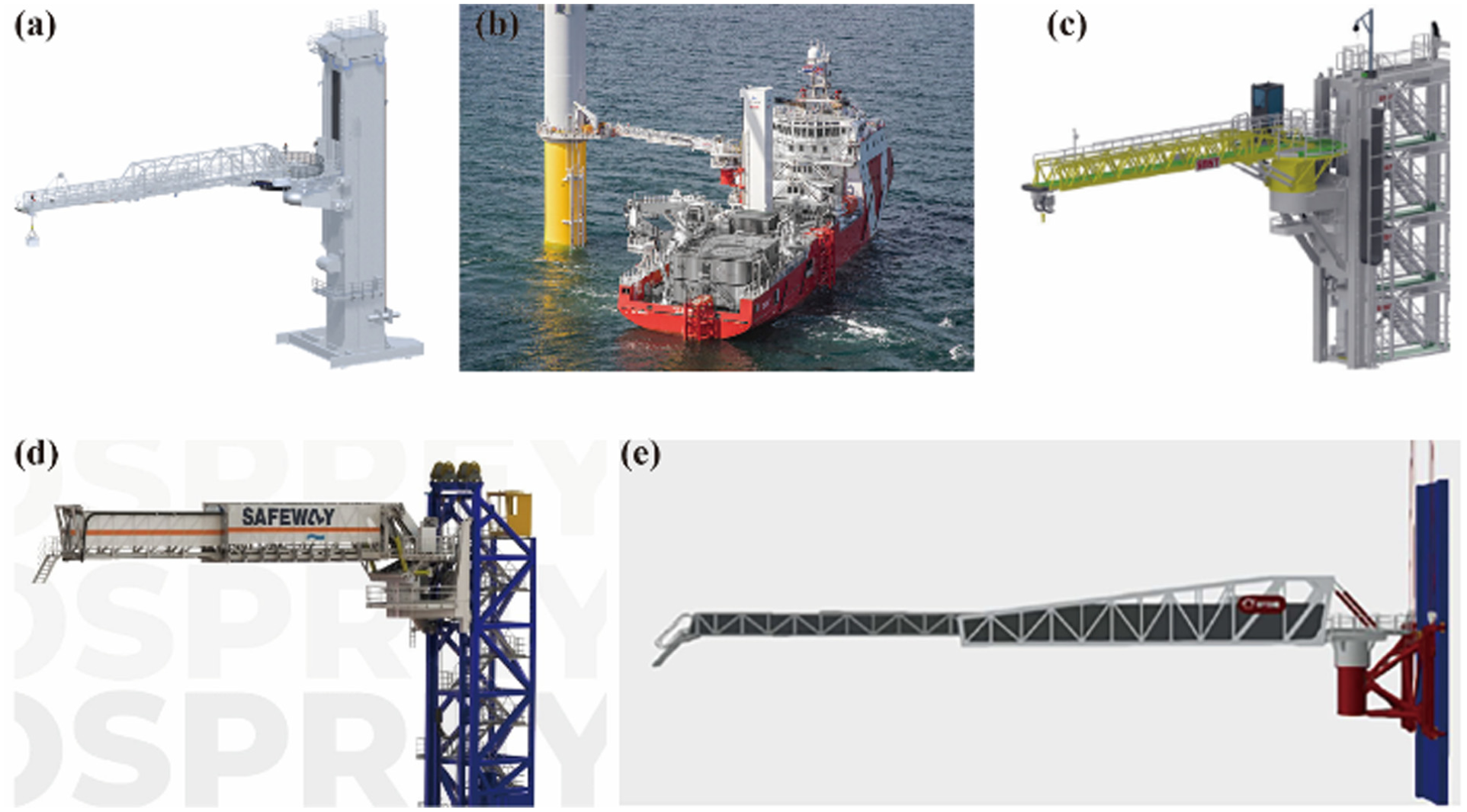
The parallel motion-compensated gangway was initially developed by Ampelmann Company, which has produced several gangway models utilizing the Stewart platform as the core motion compensation system. These models primarily include the A-type, E-type, N-type, and S-type series. Notably, the A-type and E-type systems exhibit similar structural configurations, each comprising a six-degree-of-freedom motion compensation mechanism (Stewart platform) coupled with a three-degree-of-freedom robotic arm. The principal distinction between these two lies in their operational environmental limits: the A-type is designed to function effectively in sea states with significant wave heights up to 3.0 m, whereas the E-type is engineered for conditions reaching up to 4.5 m significant wave height. The N-type model is tailored for personnel transfer in extremely cold climates, incorporating a six-degree-of-freedom motion compensation mechanism to ensure operational stability. The S-type is specifically intended for use on light vessels, facilitating continuous personnel transfer between vessels and offshore platforms, with motion compensation similarly achieved through the six-degree-of-freedom motion compensation mechanism. In addition, Shanghai Xiongcheng Marine Engineering Co., Ltd. (hereinafter referred to as Xiongcheng) introduced a six-degree-of-freedom motion-compensated gangway in 2018, designated as the “Xiongcheng Cloud Bridge.” This device serves as an access system for offshore wind turbine towers and integrates a six-degree-of-freedom motion compensation mechanism, a dual-function gangway, and comprehensive measurement, control, and warning subsystems. The system employs advanced intelligent control algorithms to actuate a hydraulic system that compensates for vessel movements across all six degrees of freedom: surge, sway, heave, roll, pitch, and yaw. Furthermore, it offers full rotational and vertical tilting capabilities. Figure 11 illustrates the majority of the parallel motion-compensated gangway products discussed herein and Figure 5(f) illustrates the structural configuration of this category of gangway. Although these gangways are capable of compensating for the host vessel’s six-degree-of-freedom motion, they require a larger deck installation area compared to serial motion-compensated gangways, and their control mechanisms exhibit greater complexity.
Products of parallel motion-compensated gangway: (a) the A-type gangway produced by Ampelmann Company 31 , (b) the E-type gangway produced by Ampelmann Company 32 , (c) the N-type gangway produced by Ampelmann Company 33 , (d) the S-type gangway produced by Ampelmann Company 34 , and (e) the six-degree-of-freedom motion-compensated gangway developed by Shanghai Xiongcheng Marine Engineering Co., Ltd. 35
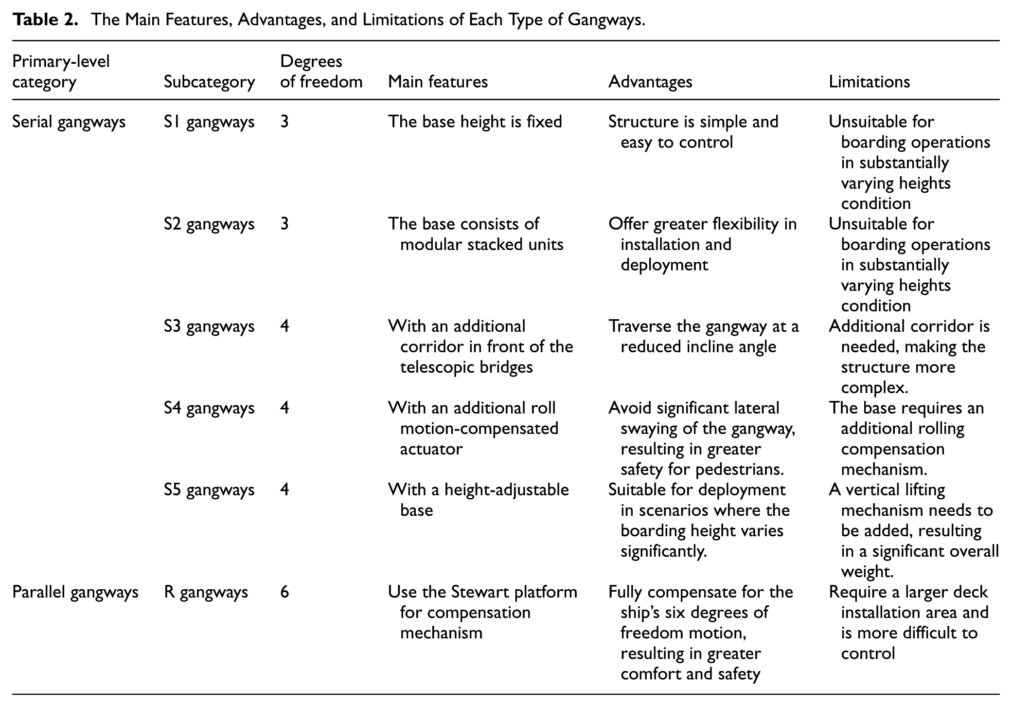
Table 1 provides the representative products of each type of gangways and their main parameters and Table 2 provides a summary of the main features, advantages, and limitations of each type of gangways. Among these, serial motion-compensated gangways represent the most prevalent category in the market, exhibiting a diverse range of structural designs. The simplest variant, characterized by a three-degree-of-freedom gangway with a fixed base, is generally unsuitable for boarding operations involving substantial height variations. Nevertheless, deployment efficiency can be improved through modular design approaches, such as three-degree-of-freedom gangways equipped with modular bases. Additionally, safety and comfort levels may be enhanced by increasing the degrees of freedom, exemplified by four-degree-of-freedom gangways. In contrast, parallel motion-compensated gangways are capable of compensating for all six degrees of freedom associated with the vessel’s movements, thereby offering superior boarding comfort relative to serial motion-compensated gangways. However, these systems demand greater deck space for installation and present increased complexity in control. As can be seen from the “Limiting wave condition Hs” in Table 1, it can be seen that serial gangway with more degrees of freedom can adapt to more severe sea conditions. With the development of offshore wind power in deep sea, modular and more flexible serial gangways have a promising future.
The Main Features, Advantages, and Limitations of Each Type of Gangways.
Material selection
Steel is the commonly employed material for gangways. 36 This is because steel has cost-effectiveness and favorable engineering properties, such as excellent weldability, which facilitate efficient fabrication and reduce production expenses. Nevertheless, to achieve weight reduction and consequently lower energy consumption during operation, aluminum alloys have increasingly been adopted as alternative materials for gangway construction. Aluminum alloys offer advantages including low density and corrosion resistance. For instance, Hu et al. from Shanghai Zhenhua Heavy Industry Co., Ltd. introduced a retractable aluminum alloy gangway system in 2019 and subsequently detailed the design methodology and analytical procedures concerning its stability, load-bearing capacity, and fatigue strength in 2020.37,38 Similarly, MME Group Company developed a lightweight aluminum gangway tailored for the offshore wind energy sector, featuring a net width of 600 mm and an operational angle range of 0–50°, compatible with steel foundation towers. 39 Additionally, Bristol Industries in Pennsylvania manufactures aluminum gangways suitable for diverse applications, including pier-to-pier connections and extended A.D.A. access ramps. 40
The transition from steel to aluminum alloys as the primary material for gangway fabrication is attributable to aluminum’s status as one of the most widely utilized non-ferrous metals in industry, offering a superior strength-to-weight ratio relative to steel and the capacity for extrusion into complex cross-sectional profiles. However, aluminum alloys present challenges in welding due to their high chemical reactivity, which leads to the formation of oxide films that can become weld inclusions. Furthermore, weld porosity and susceptibility to warping deformation during welding are common issues. Both non-age-hardened and age-hardened aluminum alloys exhibit joint strengths inferior to those of the base material when welded without subsequent post-weld heat treatment. These factors complicate the manufacturing process of aluminum alloy gangways compared to steel, resulting in increased production complexity and higher associated costs.
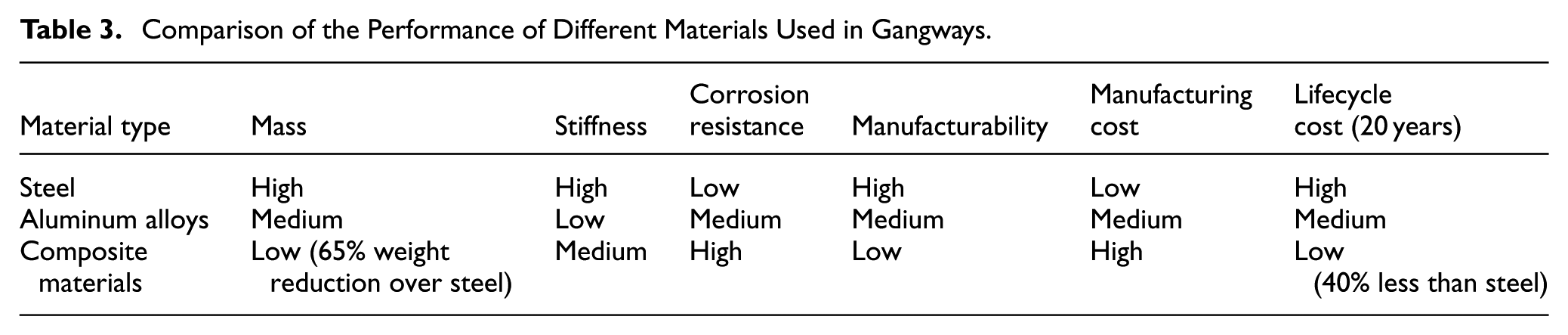
In recent years, the pursuit of weight reduction in gangways has increasingly focused on the utilization of composite materials, which offer advantages such as low density, high strength, and superior corrosion resistance. For instance, Thuijs developed a basic gangway with a mass of 1168 kg, representing a 65% weight reduction over the Ampelmann GXL gangway composed of traditional steel. 41 Similarly, Subramanian designed a composite T-boom for the Ampelmann GXL gangway and employed a fatigue model tailored to marine conditions to estimate its service life. This redesigned structure achieved a 45% decrease in weight relative to the original steel truss configuration. 42 These findings underscore the considerable potential of composite materials to diminish the overall mass of gangways, thereby enhancing their operational performance and reliability in marine environments. Nonetheless, when compared to steel counterparts, composite materials entail more intricate manufacturing procedures, elevated production costs, and their long-term reliability remains insufficiently validated. Consequently, no commercial products employing composite materials for large-scale gangways have yet been introduced to the market. A comparison of the performance of different materials used in gangways is shown in Table 3. As can be seen from Table 3, the composite materials have greater development potential as the number of products increases, considering the overall life-cycle operating costs.
Comparison of the Performance of Different Materials Used in Gangways.
Structural analyze
Contemporary structural analyses of gangways predominantly concentrate on assessing whether their yield and buckling characteristics satisfy operational requirements. 36 The prevalent methodologies employed in these analyses encompass theoretical calculations and finite element analysis. For instance, Zhang et al. utilized buckling failure criteria to determine the cross-sectional dimensions of aluminum alloy components in gangways. 38 Similarly, Qiu et al. developed a finite element model to examine the stress and displacement responses of the gangway structure under both normal operational and extreme conditions, thereby evaluating the design’s feasibility. 43 Xu et al. also constructed a finite element model to analyze the stress-strain behavior of the gangway, identifying locations of maximum stress and strain, which informed targeted structural reinforcements. 2 However, the gangways are subjected to persistent wave and wind excitations during operation, which induce complex vibrational responses in critical components. Such intense vibrations, particularly those occurring under resonance conditions, can precipitate fatigue damage in these key structural elements. The progressive accumulation of fatigue damage consequently compromises the reliability and safety of the gangway. Hence, it is imperative to investigate impact of fatigue, vibration, resonance, durability, etc. on structural reliability during the structural design phase to ensure the gangway’s durability and operational integrity.
Modal analysis constitutes the fundamental basis for a comprehensive examination of the vibration characteristics of gangways and their critical components. Therefore, it is imperative to analyze the modal properties of these key components to elucidate their vibration mechanisms, which in turn facilitates the development of optimal design strategies for both the gangway and its essential parts. Furthermore, hydraulic dampers represent the primary devices employed for vibration suppression, with the majority of gangways being hydraulically actuated. Consequently, the design of hydraulic systems offers a relatively straightforward approach to developing hydraulic dampers and other vibration mitigation devices aimed at reducing gangway vibrations. However, current research and design practices concerning gangways have largely overlooked the effects of vibrations and have not implemented corresponding vibration elimination measures. Moving forward, to improve the stability of gangways, it is essential to incorporate the study of vibration mechanisms under continuous excitation from wave and wind forces. Additionally, the integration of vibration mitigation solutions, such as hydraulic dampers designed in coordination with hydraulic systems, should be systematically considered.
System modeling
With the development of modeling technology, current system modeling methods have become diversified: there are traditional methods such as mathematical modeling and computer simulation modeling based on formula derivation, as well as advanced data-driven modeling methods. Traditional modeling relies on physical laws, which can lead to difficulties or even make modeling impossible when equations cannot be established based on physical laws. Data-driven modeling methods mainly rely on historical data, statistics, machine learning, and deep learning to learn the input-output patterns. They do not require prior physical formulas or mechanistic equations and mainly rely on datasets for modeling. They have a low barrier to entry, but may violate physical laws and are not suitable for all application scenarios. Therefore, some physics-embedding system modeling methods embed physical or mathematical knowledge into the model to ensure modeling accuracy were proposed.44,45 To ensure the safe operation of gangways under specific sea conditions, it is essential to analyze the motion characteristics of the gangway’s terminal landing point or the gangway body itself within those conditions. Since the movement of the gangway’s terminal landing point or body is influenced by both the host vessel’s motion and the gangway’s installation location on the vessel, a systematic modeling approach is required. Since datasets for gangways are not readily available, the current modeling methods used are mainly traditional methods, namely mathematical modeling or computer simulation modeling. This involves first developing a wave model to simulate the wave dynamics characteristic of the given sea state, followed by constructing a ship model to determine the ship’s motion response to wave excitation. Subsequently, a gangway motion model is established based on its mounting position on the ship to assess the motion behavior of the gangway’s terminal landing point or installation platform under the specified sea conditions. Building upon this framework, motion-compensated control can be achieved through the design of compensation mechanisms and the development of corresponding control hardware and algorithms. The modeling procedure is illustrated in Figure 12.
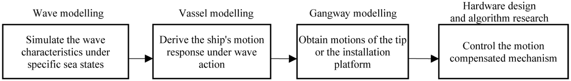
The modeling procedure for gangways.
Wave modeling
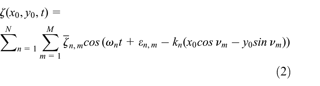
Wave phenomena in the ocean represent a complex mode of energy transfer resulting from the interplay of multiple forces acting upon seawater. From an energetic standpoint, wave generation is the process through which wind imparts energy to the water surface. Given the inherently stochastic nature of wind speed and direction, the resulting wave motions exhibit random characteristics. Nevertheless, long-term empirical observations indicate that these unstable waves are not entirely random; rather, wave height and period conform to identifiable statistical distributions. To quantify this randomness, wave spectra are frequently employed to characterize the distribution of wave energy across frequencies. Prominent examples of such spectra include the Pierson-Moskowitz (PM) spectrum, 46 the Bretschneider spectrum, 47 and the JONSWAP spectrum, 48 among others. Because wave spectral formulations incorporate parameters that describe specific sea states, they can effectively represent particular sea conditions, such as the third sea state or other defined sea state levels. However, wave spectra inherently describe sea state characteristics solely in the frequency domain, lacking an intuitive representation in the temporal domain. Consequently, it is essential to transform the spectral description of sea conditions into a temporal wave model. This transformation can be achieved by applying the inverse fast Fourier transform, which reconstructs the sea state as a superposition of multiple harmonic components. The mathematical expression for unidirectional waves, also referred to as long-crested waves, is derived as follows 49 :
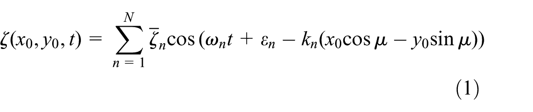
Where ζ n denotes the amplitude of the nth harmonic component, εn represents the phase angle associated with the nth harmonic component, k n indicates the total number of harmonic components, and μ specifies the direction of the harmonic component.
Multidirectional waves, often referred to as short-crested waves, can be modeled as the superposition of numerous unidirectional wave components. Consequently, their mathematical representation can be obtained through the application of linear wave theory. 49
Based on equations (1) and (2), the wave heights corresponding to long-crested and short-crested waves are illustrated in Figure 13(a) and (b), respectively. In the subsequent ship modeling, the ship is treated as a system to be analyzed, with the wave height equations serving as inputs and the ship’s motion response as the output, the motion response under specific sea conditions (such as Sea State 4) can thus be calculated.
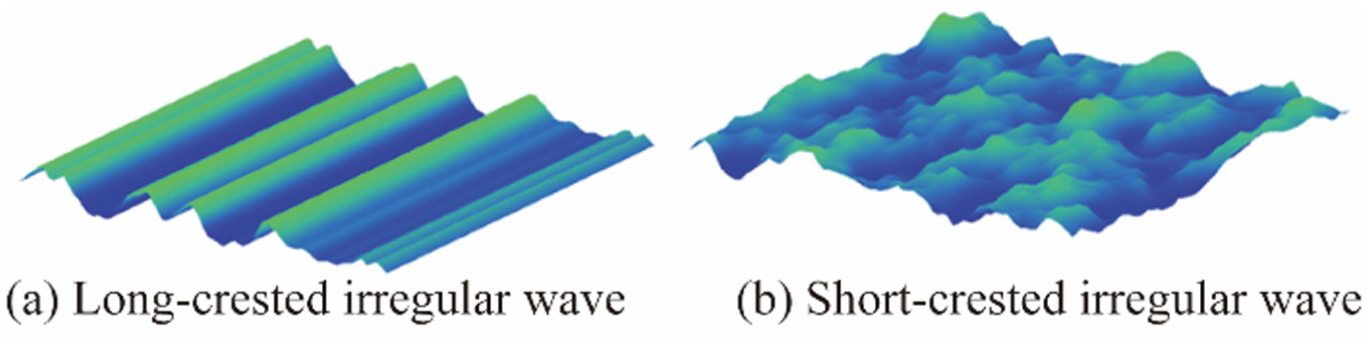
Wave surfaces of long-crested wave and short-crested wave: (a) wave surface of long-crested wave, (b) wave surface of short-crested wave. 49
Ship modeling
Presently, the prevalent approaches for determining ship motion encompass mathematical techniques grounded in linear theory as well as computational simulation methods. Notably, the mathematical approach is founded upon the following theoretical framework 49,50:
When a vessel is subjected to regular (harmonic) wave conditions, the resultant ship response induced by wave excitation is likewise harmonic, exhibiting the same frequency as the incident waves. Denoting the angular frequency of the regular waves as ω, the corresponding ship motion response can be expressed as:

Where F x (t) denotes one of the ship’s motion responses, including surge, sway, heave, roll, pitch, or yaw. A represents the amplitude, Δα signifies the phase difference between the ship’s motion response and the wave, and t denotes time.
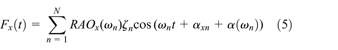
In the harmonic scenario, assuming that the amplitude of the ship’s motion in each degree of freedom is linearly proportional to the wave amplitude, and that this relationship is characterized by the response amplitude operator (RAO), the ship’s motion response can be further formulated as follows:

Where RAO x represents the ship’s motion response amplitude operator, which depends not only on the ship’s shape and weight but also on the direction of the incoming waves. ζ denotes the wave amplitude, α x is the wave’s phase shift, and α represents the phase difference between the ship’s motion response at its center of gravity and the wave.
When the ship encounters unidirectional irregular waves, its response to the irregular excitation caused by these waves can be considered as the sum of harmonic response components. Thus, the ship’s motion response under irregular wave conditions can be determined using the principle of linear superposition.
Analogous to multi-directional irregular waves, which can be conceptualized as the superposition of unidirectional irregular wave components propagating in various directions, the ship’s motion response to such multi-directional irregular waves can be determined by applying the principle of linear superposition. While this linear theoretical approach facilitates relatively straightforward computation of the ship’s motion response, it exhibits notable limitations and is inadequate for precise prediction. This inadequacy arises because the actual ship motion response is inherently nonlinear, owing to the complex nature of wave dynamics and the nonlinear geometric characteristics of the vessel. Furthermore, as we can know from control engineering theory, 51 even for linear systems, the response caused by the input includes both transient and steady-state responses. However, the calculation method used above only calculates the steady-state response and ignores the transient response, resulting in low calculation accuracy.
An alternative approach for calculating ship motion response involves computational simulation methods, primarily encompassing two frameworks: potential flow theory and computational fluid dynamics (CFD). Historically, potential flow theory has been predominantly employed in early investigations of motion responses for maritime structures such as ships and floating production storage and offloading units (FPSOs). Notable examples include the far-field method introduced by Newman 52 and the near-field method developed by Pinkster and Oortmerssen. 53 However, potential flow theory is limited in its capacity to incorporate fluid viscosity and strong nonlinear effects, thereby failing to fully capture the complexities encountered in practical engineering scenarios. For instance, Inoue and Islam 54 applied both near-field and far-field methods to compute the drift force on a liquefied natural gas FPSO (LNG-FPSO), revealing through comparison with experimental model tests that neglecting viscous effects results in significant prediction errors.
With advancements in computational technology and numerical methodologies, CFD approaches have garnered increasing attention due to their capability to model fluid viscosity and nonlinear phenomena more accurately. Wu and Zhang 55 employed a CFD method based on the Unsteady Reynolds-Averaged Navier-Stokes (URANS) equations to predict additional drag induced by pitching, rolling, and wave interactions. Their findings suggest that, relative to other numerical techniques, CFD methods provide more effective predictions of additional drag forces in wave-ship interactions. Similarly, Wang et al. 56 utilized CFD to estimate the average drift force and motion response of an FPSO, observing that CFD tends to overestimate the average drift force compared to potential flow models. Li and Wang 57 implemented the CFD solver naoe-FOAM-SJTU to numerically simulate the hydrodynamic performance of a single-point moored FPSO, validating the solver’s accuracy and highlighting the advantages of CFD in capturing strong nonlinear phenomena. Nonetheless, the underlying mechanisms governing strong nonlinear wave forces remain insufficiently understood, and no robust predictive model for such nonlinear wave loads has yet been established.
A comparative analysis of the two aforementioned computational simulation approaches reveals distinct characteristics. Potential flow theory neglects viscous effects and simplifies the Navier-Stokes (N-S) equations by representing the flow field through a velocity potential that satisfies the Laplace equation within the fluid domain, thereby formulating the problem as a boundary value problem. Owing to its computational efficiency, potential flow theory is extensively utilized in the analysis of ship motion responses. Conversely, computational fluid dynamics (CFD) methods endeavor to solve the full Navier-Stokes equations, offering a detailed and comprehensive representation of the flow field that accounts for fluid viscosity and nonlinear interactions between waves and ships. Despite their enhanced accuracy, CFD approaches demand substantial computational resources, resulting in extended computation times that constrain their practical application. Nonetheless, ongoing advancements in computational capabilities have facilitated the increasing adoption of CFD methods, enabling more precise simulation outcomes.
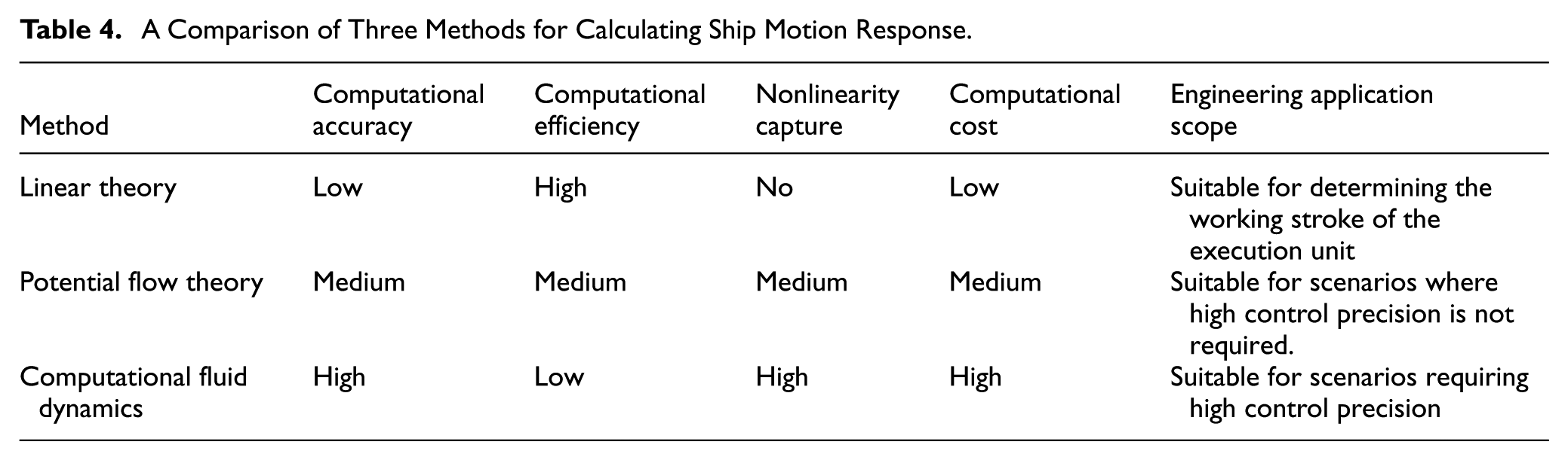
In summary, among the three methods for calculating ship motion, the linear theory method is the simplest, but its results are the coarsest because it ignores nonlinearity and only considers steady-state response. The computer simulation method based on potential flow theory, which does not consider fluid viscosity and strong nonlinear effects, yields better results than the linear theory method, although there are some errors between the calculated and actual results. Furthermore, it is widely used in engineering because it consumes relatively few computational resources. The CFD method considers fluid viscosity and nonlinear effects, consumes significant computational resources, and its results are closer to reality; it can be considered when computer performance is good. A comparison of the three methods for calculating ship motion response is shown in Table 4.
A Comparison of Three Methods for Calculating Ship Motion Response.
Gangway modeling
The determination of the motion response of a gangway is contingent upon the specific type of its motion-compensated mechanism, as different mechanisms are designed to achieve distinct compensation objectives. In the case of a serial-type motion-compensated mechanism, the primary goal is to keep the landing point fixed relative to the target platform. Consequently, it is necessary to compute the motion response of the gangway’s landing point (denoted as point A in Figure 14(a)). Conversely, for a parallel-type motion-compensated mechanism, the objective is to maintain the gangway’s installation platform stationary with respect to the inertial frame. Therefore, the motion response of the gangway’s installation platform (represented as a coordinate system OA-XAYAZA in Figure 14(b)) must be calculated.
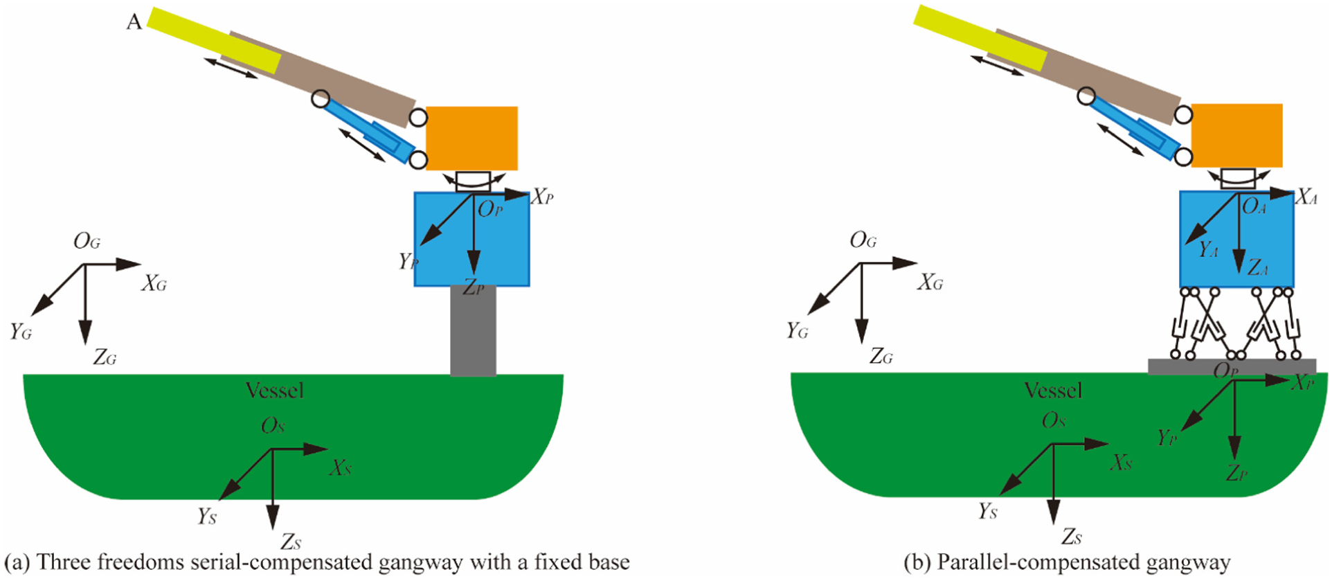
Determination of the motion response of a gangway: (a) the serial-compensated gangway and (b) the parallel-compensated gangway.
In the analysis of the motion response of either serial or parallel motion-compensated mechanisms, it is essential to define three distinct coordinate systems 8,10: the inertial coordinate system OG-XGYGZG, the object coordinate system OS-XSYSZS, and the fixed platform coordinate system OP-XPYPZP. The inertial coordinate system is anchored to the Earth, serving as a global reference frame. The object coordinate system is attached to the mother vessel of the gangway, with its origin typically located at the vessel’s center of gravity. The fixed platform coordinate system is affixed to the installation base of the gangway, as illustrated in Figure 14. These coordinate systems are established to accurately determine the displacement of the gangway’s installation base in response to various vessel motions and it falls under the category of ship modeling. In the case of a serial motion-compensated mechanism, the motion response at the landing point resembles the end-effector movement of a conventional serial robot. Given that the Denavit-Hartenberg (DH) model is well-suited for characterizing the end-effector motion of serial robots, it can be effectively employed to compute the landing point’s motion response. Conversely, for parallel motion-compensated mechanisms, the motion response of the installation platform depends on the lengths of the six links constituting the Stewart platform. It can be solved algebraically using a combination of Gröbner basis elimination and Sylvester junction elimination. 58
Experimental verification methods
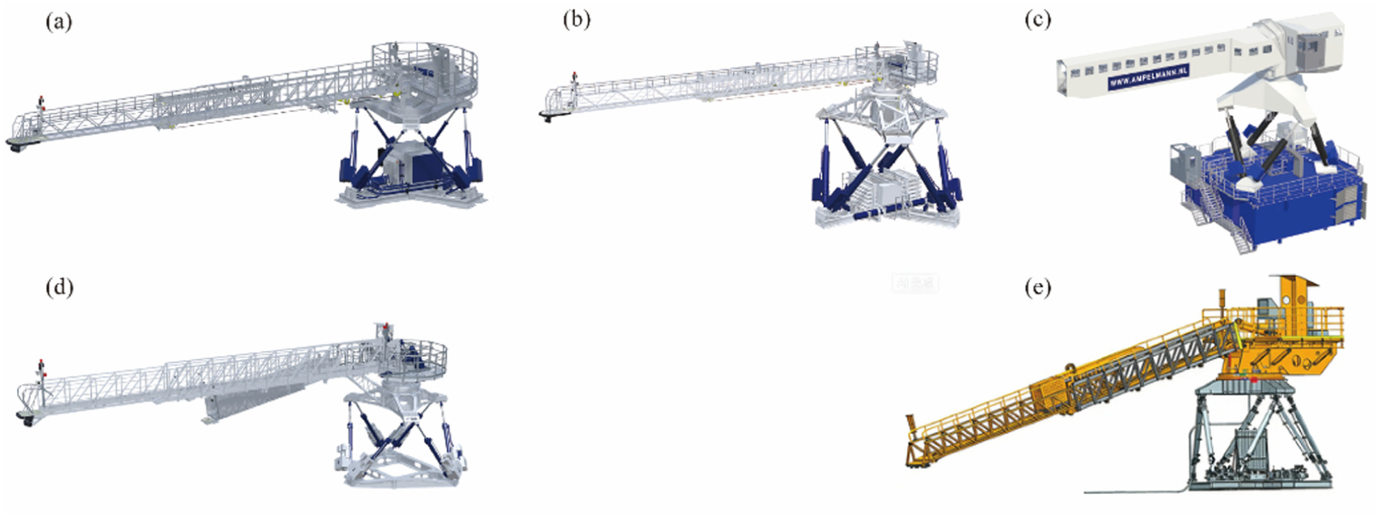
The aforementioned modeling methods mainly employ mathematical formula derivation or simulation software, and the accuracy of the results needs to be verified through actual measurements. To verify the accuracy of the modeling and the effectiveness of motion compensation, two main practical methods are currently used: dry testing and wet testing, as shown in Figure 15. In dry testing, the ship’s motion is simulated by the lower Stewart platform, while the upper Stewart platform simulates the motion compensation mechanism of the parallel gangways. Because the lower Stewart platform can generate not only single-degree-of-freedom motion but also combined motions of multiple degrees of freedom, this verification method can individually verify the modeling accuracy and compensation effect of the gangways under single-degree-of-freedom and multi-degree-of-freedom motions. However, it is difficult to simulate ship motion under real sea conditions. Therefore, this method is more suitable for early-stage design verification but is less suitable for verification under real sea conditions. In wet testing, the ship’s motion is simulated by a scaled-down ship model. This method closely resembles actual sea conditions, and the measured data is more accurate. However, the problems include high manufacturing costs and long testing cycles, which is why it is less commonly used in practice. Whether it is a dry test or a wet test, when testing the motion compensation effect of the compensation mechanism, two reference points can be set on the upper plane of the Stewart platform, which is a parallel compensation mechanism, and a laser beam can be set at a distance to be directed at these two reference points. The compensation accuracy can be determined by measuring the displacement of the laser beam relative to the reference points.
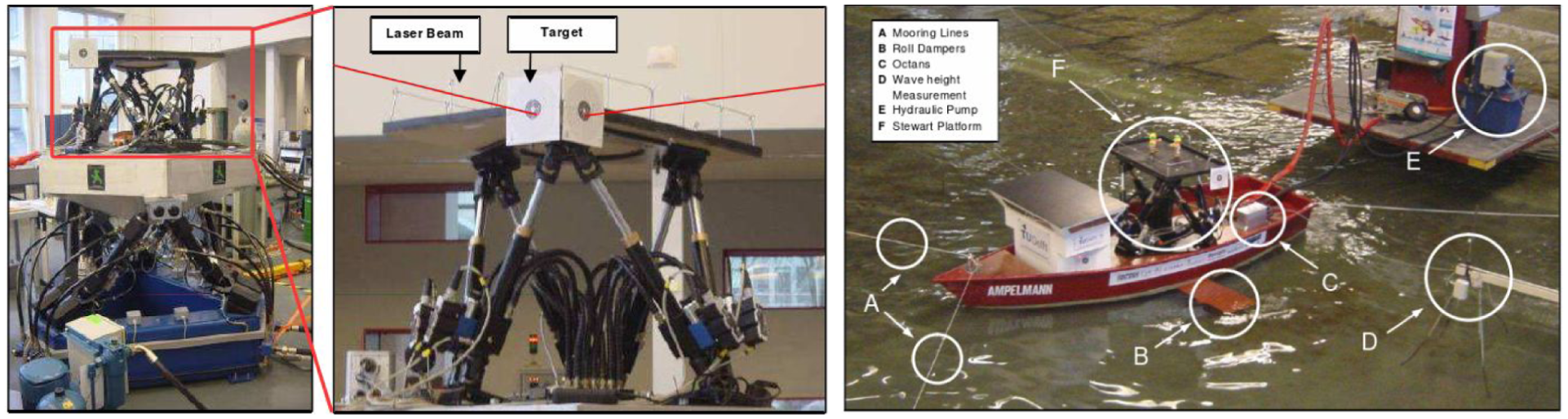
Two practical experimental verification methods: dry test and wet test. 50
Control system
The control system of the gangway constitutes a critical element in ensuring its stability and safety. This system comprises three primary components: the detection unit, the control unit, and the execution unit. As depicted in Figure 16, the detection unit is tasked with monitoring the movements of the mother ship, utilizing either a single sensor or a multi-sensor fusion detection approach. Commonly employed sensors within this unit include accelerometers and gyroscopes. Serving as the central component, the control unit processes sensor data and executes control algorithms. Predominant control strategies implemented in this context encompass proportional-integral-derivative (PID) control, fuzzy control, and sliding mode control, among others. The execution unit, responsible for mechanical motion compensation, consists of various types of drive mechanisms. Typical actuators employed in the execution unit include hydraulic cylinders, hydraulic motors, electric motors, and electric cylinders.
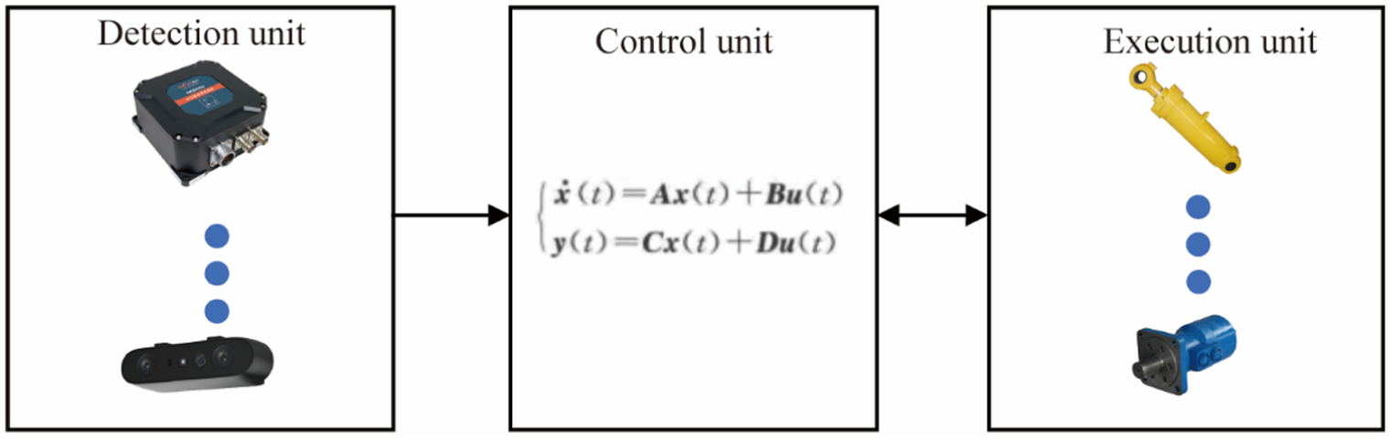
Composition of the gangway’s control system.
Detection unit
The detection system must be capable of accurately measuring the six degrees of freedom (six-DOF) motions of the mother ship to which the gangway is affixed. To achieve these measurements, various detection modules can be employed, including inertial detection modules, machine vision detection modules, laser detection modules, and multi-module fusion detection systems.59,60 Among these, micro-inertial sensors based on microelectromechanical systems (MEMS), comprising micro-accelerometers and micro-gyroscopes, are the most commonly utilized inertial measurement units. The acceleration data obtained from the micro-accelerometers can be integrated once over time to derive the velocity of the mother ship, and integrated twice to determine its displacement, thereby providing incremental positional changes. Concurrently, micro-gyroscopes measure the rotational angular velocity of the vessel. By fusing data from both sensor types, comprehensive six-DOF motion measurements of the mother ship can be obtained. However, due to the influence of stochastic factors and external interferences, these detection modules inherently exhibit measurement errors. To enhance measurement accuracy, various methodologies have been proposed. Li 61 employed Extended Kalman Filters (EKF) to process the measured displacement associated with the ship’s heave motion, effectively reducing measurement errors. Nevertheless, this approach necessitates prior knowledge of the heave motion’s frequency characteristics to select appropriate filter parameters, thereby limiting its adaptability under varying operational conditions. Building upon the ship’s pitch motion model and spectral analysis techniques, Lu et al. 62 developed an analytical model elucidating the relationship between acceleration measurements from the inertial measurement unit (IMU) and the state variables of the ship’s pitch motion. In their study, pitch motion filtering was conducted using the Unscented Kalman Filter (UKF) algorithm, which demonstrated faster convergence rates and superior measurement accuracy compared to the EKF approach.
In conventional methods for measuring the ship’s instantaneous linear motion, the output of the Infinite Impulse Response (IIR) digital high-pass filter exhibits phase lead, causing the output signal to precede the actual signal temporally. To address this issue, Yuan et al. 63 proposed a ship instantaneous linear motion measurement technique based on adaptive frequency estimation. Simulation results indicate that this enhanced strapdown instantaneous linear motion measurement method effectively mitigates the temporal lead problem inherent in traditional approaches, thereby enabling real-time and precise measurement of the ship’s instantaneous linear motion.
In the context of employing various modules such as the machine vision detection system, Merriaux et al. 64 demonstrated that a gangway relying exclusively on an inertial system cannot be securely positioned without mechanical fixation. Consequently, they proposed a real-time approach to monitor the gangway’s position relative to the offshore wind turbine, utilizing robust techniques to detect and estimate the turbine’s position within a two-dimensional scatter plot. Their results indicate that this method achieves real-time measurement accuracy at the centimeter scale. Cui 65 developed a six-degree-of-freedom pose detection system for moving targets based on stereo vision. This system incorporated studies on camera calibration and stereo rectification, image feature extraction, stereo matching and feature tracking, as well as pose estimation. Sun et al. 66 introduced a pose measurement technique that fuses inertial measurement unit (IMU) data with monocular vision, while Chen 67 proposed a method integrating stereo vision and lidar data.
Collectively, these studies illustrate that regardless of whether inertial detection modules, machine vision systems, laser detection modules, or multi-sensor fusion approaches are employed, the primary objective remains the enhancement of detection accuracy concerning the motion of the mother ship. Beyond the utilization of diverse hardware configurations, the integration of advanced data processing methodologies also constitutes a significant strategy for improving detection precision.
Control unit
The control unit is responsible for computing the control output based on the motion of the mother ship, as measured by the detection unit, and subsequently transmitting control commands to the motion-compensated actuator. Prior to determining the control output, it is essential to develop a dynamic model of the gangway. To design an effective controller, Yin et al. 68 formulated the Stewart-Gangway system model using the Kane method and subsequently developed a robust controller grounded in this model. The primary control objective was to maintain the Stewart platform in a stationary state despite external disturbances and time-varying input delays. Simulation results demonstrated the efficacy and performance of the proposed controller. Liang et al. 69 focused on a gangway equipped with a serial compensation mechanism, employing the Euler-Lagrange equations to derive the system’s kinematic and dynamic equations. In their study, the supply ship was modeled as a six-degree-of-freedom dynamic positioning (DP) system. Following an analysis of the supply ship’s motion within a channel, an enhanced dynamic controller was designed. Simulations were performed under two conditions: motion along the desired trajectory of the gangway’s land tip and the process of connecting to the target. The findings indicated that the implemented controller significantly reduced steady-state error and demonstrated practical applicability. Zhang et al. 70 developed a compensation system model incorporating servo motors and electric cylinders via a mechanistic approach, and designed a backstepping control strategy to track the ship’s heave motion. Particle swarm optimization was employed to optimize the control parameters, and the performance of the optimized backstepping controller was evaluated through MATLAB/Simulink simulations. Results revealed that the proposed optimized backstepping control method achieved a compensation efficiency exceeding 75.0%. Yin et al. 10 posited that the low-frequency responses of the longitudinal, transverse, and heave motions of an offshore wind power service operation vessel (SOV) are regulated by the DP system, while residual motion responses are compensated by an active parallel platform. They introduced a time-domain modeling and controller design approach that accounts for the coupled dynamics of the SOV and the active parallel platform. This method involves solving the Cummins equation to obtain the SOV’s motion response, substituting the convolution component with a state-space model, and rapidly solving the control algorithm using system identification techniques. The validity of the approach was confirmed through Bode plot analysis. Wei et al. 11 introduced an inverse kinematics solution approach for hybrid systems utilizing a fuzzy algorithm to mitigate wave-induced disturbances in hybrid mechanisms. The proposed method begins by deriving the Jacobian matrix of the hybrid mechanism to establish the relationship between angular and linear velocities within the joint space and those of the end-effector in the task space. Subsequently, numerical integration techniques are employed to compute the inverse kinematics solution. Given that the hybrid mechanism comprises a six-degree-of-freedom Stewart platform coupled with a three-degree-of-freedom moving platform, challenges arise due to kinematic redundancy and the non-uniqueness of the inverse kinematic solutions. To address this, a fuzzy logic-based strategy is implemented to judiciously determine the variable values. The efficacy and robustness of the proposed method are validated through numerical simulations under conditions involving wave disturbances in the hybrid boarding system.
In summary, the design and development of control units necessitate consideration beyond the control units themselves, often requiring integration of the motion characteristics of the mother ship and the actuators of the gangway. A notable limitation in current research is that control performance evaluations predominantly rely on simulation-based methods, with a lack of experimental validation under real marine operational conditions
Actuator unit
The actuator unit serves as the mechanism responsible for maneuvering the gangway to establish a connection with the boarding target, thereby facilitating motion compensation. Predominantly, hydraulic actuators—such as hydraulic cylinders and hydraulic motors—are employed for this purpose. This preference is attributed to the high power-to-weight ratio of hydraulic actuators and their relative ease of deployment. Furthermore, the inherent compressibility of hydraulic fluid within these actuators provides a means to mitigate impact loads, thereby preventing damage during operational activities. Overload protection is also achievable through the integration of relief valves within the hydraulic system.
Alternatively, electric actuators, including electric cylinders and electric motors, are utilized. Although electric actuators generally exhibit a lower power-to-mass ratio compared to their hydraulic counterparts and lack the impact absorption benefits inherent to hydraulic systems, they offer distinct advantages. Notably, electric actuators can be directly powered by the ship’s electrical system without necessitating intermediate energy conversion, resulting in reduced energy consumption and the elimination of hydraulic fluid contamination. Consequently, electric actuators present a cleaner and more environmentally sustainable option relative to hydraulic actuators.
A prevalent form of electric cylinder converts the rotational motion of an electric motor into linear motion via a lead screw and nut mechanism. The external and internal configurations of this actuator type are depicted in Figure 17(a) and (b), respectively. While this design is widely adopted across various industrial sectors, it is constrained by stringent installation precision requirements for internal components, limited load-bearing capacity, and vulnerability to impact loads. Recent technological advancements have led to the development of electric cylinders capable of driving heavier loads. For instance, RISE Robotics, a company established by alumni of the Massachusetts Institute of Technology and the Rhode Island School of Design, has engineered a high-reduction belt-driven linear actuator.71,72 The external and internal structures of this actuator are illustrated in Figure 17(c) and (d), respectively. This actuator demonstrates exceptional precision, speed, and weight characteristics, with the capacity to withstand certain impact forces. Moreover, it achieves energy consumption levels approximately 90% lower than those of hydraulic systems. Compared to other mechatronic actuators, it offers superior cost-effectiveness, durability, extended stroke length, and higher operational speed. These attributes underscore its potential as a promising alternative to hydraulic cylinders for actuator units in heavy machinery applications.
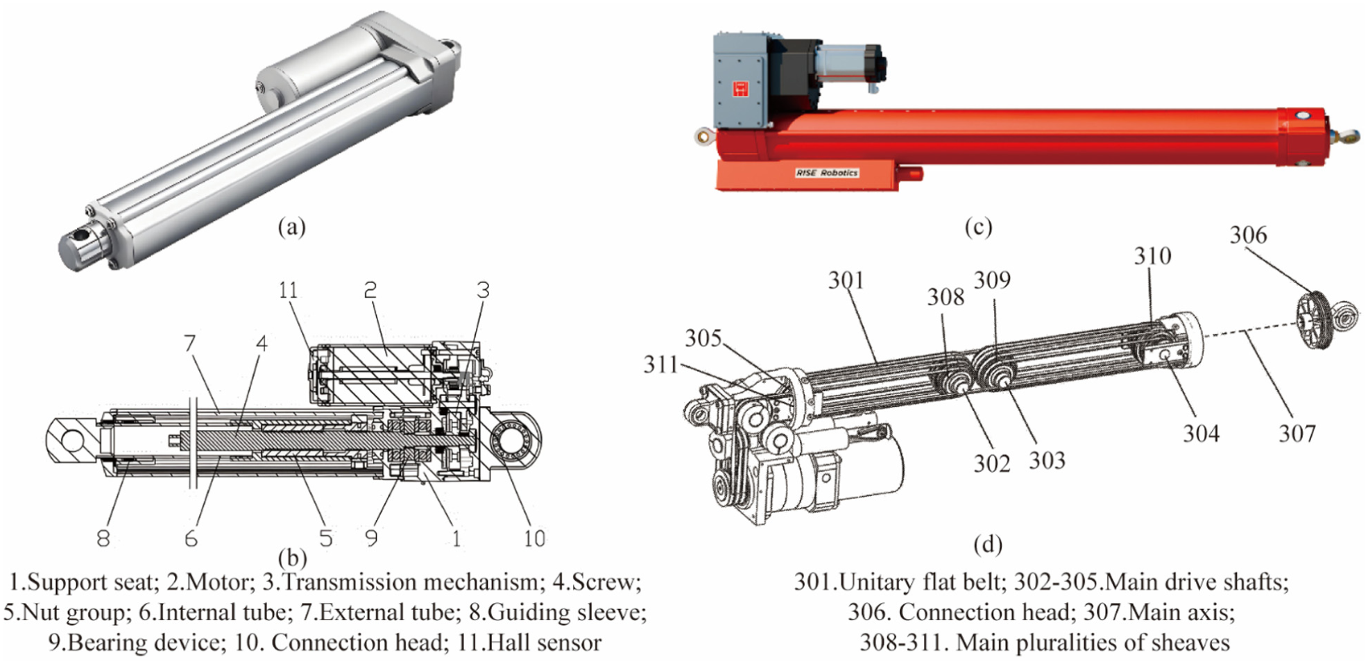
Conventional electric cylinder and novel electric cylinder: (a) external configuration of traditional electric cylinder, (b) internal configuration of novel traditional cylinder, (c) external composition of novel electric cylinders, and (d) internal composition of novel electric cylinders.
In the selection process of actuators for gangways, hydraulic and electric actuators may be chosen either individually or in combination, contingent upon the operational requirements of the actuator, including factors such as maximum load capacity and the occurrence of impact loads. Regardless of the actuator type selected, the primary objective remains to reduce the overall weight of the gangway and to minimize energy consumption. Furthermore, the exploration of innovative actuator designs is essential for the development of novel actuators capable of handling heavy loads and enduring impact forces, thereby facilitating the achievement of full electrification in gangway systems.
Other design methods
As discussed previously, the existing motion compensation systems for gangways predominantly employ either serial or parallel mechanisms, which may constrain the scope of design approaches available to researchers. In the design of gangway, it is feasible to expand conceptual frameworks by drawing inspiration from natural systems, such as the head stabilization mechanisms observed in birds and poultry. When birds or poultry focus their gaze on a target, their heads remain stable despite substantial movement of their bodies. This phenomenon closely parallels the control demands associated with gangways’ stability, as demonstrated in Figure 18. Accordingly, the principles underlying avian head stabilization can serve as a valuable source of inspiration for the development of biomimetic gangway designs, potentially improving the stability and safety of boarding procedures.
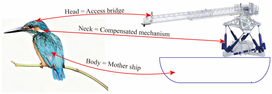
Comparison between the stabilization control of a bird’s head and the stabilization control of a gangway.
Empirical studies indicate that the maintenance of clear vision constitutes a fundamental survival mechanism in avian species.73,74 Unlike humans, birds lack compensatory eye movement mechanisms within their retinas; consequently, if a bird’s head is not stabilized during locomotion, the resultant retinal image shifts, leading to blurred vision and impaired spatial orientation. Therefore, head stability is essential for preserving visual clarity. This stability predominantly depends on the vestibulo-ocular reflex (VOR) system. The vestibular apparatus within the avian inner ear rapidly detects angular acceleration, linear acceleration, and postural changes, while the retina monitors visual field stability. During bodily movements such as flight or ambulation, vestibular sensors transmit immediate signals to the brainstem, which subsequently orchestrates precise antagonistic contractions or relaxations of the neck musculature. This neuromuscular response induces neck rotation counter to the body’s motion, thereby mitigating displacement and maintaining the head’s orientation or level position relative to the target.75,76 Biomimetic applications inspired by avian head stabilization principles have yielded substantial advancements in domains including drone gimbal technology,77,78 robotic vision systems,79,80 and image stabilization devices, 81 underscoring the significant potential of translating biological insights into engineering innovations. For instance, by emulating the head stabilization mechanisms observed in birds such as chickens, contemporary camera systems can achieve stable image capture under dynamic conditions, including handheld operation and action filming.
In addition to avian species, insects also necessitate visual stabilization mechanisms to mitigate motion blur and prevent image rotation. Subsequent investigations have demonstrated that insects possess intrinsic balance systems, which depend on their antennae and other sensory organs.82,83 The antennae are equipped with sensors capable of detecting acceleration and directional changes, thereby facilitating balance maintenance during flight and locomotion. Moreover, the visual system plays a pivotal role in modulating posture in response to dynamic visual stimuli. Although insects lack the vestibular apparatus characteristic of vertebrates, they accomplish analogous functions through specialized physiological structures and sensory modalities. This phenomenon exemplifies the diverse evolutionary adaptations organisms have developed to thrive within their respective environments, highlighting a compelling instance of biological diversity.
Collectively, these studies underscore that both birds and insects exhibit compensatory head movements analogous to the wave compensation observed in gangways. Accordingly, biomimetic principles derived from these biological systems may inform future research on gangway design, as follows:
Investigate the internal architecture of cervical vertebrae units in birds or insects, utilizing these structures as prototypes to develop fundamental mechanical units that connect the gangway body to the installation platform.
Examine the connective mechanisms of cervical vertebrae units in these organisms to design connection structures between the basic mechanical units, potentially incorporating elastic elements, damping components, and various kinematic pairs such as rotational and translational joints.
Analyze the muscle-driven actuation principles of cervical vertebrae units to engineer drive mechanisms between the mechanical units of the gangway, which may include linear and angular displacement actuators.
Explore the sensory mechanisms underlying movement compensation in birds and insects to propose suitable sensing, detection, and control strategies aimed at achieving closed-loop control of the gangway system.
Conclusions
Gangways have broad prospects in many scenarios such as maritime rescue, offshore oil and gas development, and offshore wind power operation and maintenance. Continuously improving their safety and stability under complex sea conditions and reducing energy consumption is their ongoing goal. The realization of this goal requires the mutual advancement of mechanical structure, modeling methods, and control means. This paper analyzes the current status and existing problems of gangways from the aspects of structural design, modeling methods, and control systems, and proposes future development based on this. The main conclusions are as follows:
From the perspective of structural design, existing gangways include two types: serial and parallel. Among them, serial gangways are the most common type on the market. Their structural forms are diverse. Although their comfort is not as good as that of parallel gangways, the safety and comfort of passage can be improved by increasing degrees of freedom, and the convenience of deployment can be increased modular design. In contrast, parallel gangways can compensate for all six degrees of freedom of ship movement, and have superior boarding comfort compared to serial gangways. However, parallel gangways require more deck space for installation, and the control complexity is also higher. With the development of offshore wind power in deep sea, modular and more flexible serial gangways have a promising future. In terms of material selection for structural design, steel is currently the main material used for gangways. Emerging composite materials, although having higher initial manufacturing costs, have greater development potential as the number of products increases, considering the overall life-cycle operating costs. In the strength analysis of structural design, the current focus is mainly on static strength. Future research should consider the influence of factors such as fatigue, vibration, resonance, and durability on strength.
Regarding modeling methods, in order to solve the motion response of the compensation point and facilitate subsequent motion control, modeling involves three aspects: waves, ships, and gangways. The purpose of wave modeling is to convert the spectral parameters under the target sea state into time-domain functions, mainly using the inverse fast Fourier transform. Ship modeling is to solve the ship’s motion response under the target sea state. For rough calculations, linear theory can be used; for more accurate results, simulation methods based on potential flow theory and computational fluid dynamics simulation methods can be used. However, the more accurate the results, the more computational resources are required. The modeling of the gangway involves calculating the motion response of the compensation points based on the gangway’s installation location and the ship’s motion. Since the compensation targets and actuators of serial and parallel gangways differ, the calculation methods also differ: serial gangways primarily use the DH model, while parallel gangways can be solved algebraically using a combination of Gröbner basis elimination and Sylvester junction elimination.
In terms of control system design, detection units, control units, and execution units are involved. The detection unit is used to detect the motion of the mother ship. It can use individual inertial detection modules, machine vision systems, or laser detection modules, or it can use multiple modules simultaneously combined with advanced algorithms (such as Extended Kalman Filters and Unscented Kalman Filters) to improve detection accuracy. The control unit is the foundation for executing control algorithms. Current main control algorithms include PID algorithms and fuzzy algorithms. To further improve accuracy, more intelligent algorithms such as artificial intelligence can be applied, enabling the control unit to have self-learning and adaptive capabilities. Hydraulic actuators are commonly used in current applications. However, with increasing demands for energy conservation and environmental protection, electric actuators, driven directly by electricity, are the future development direction due to their higher energy conversion efficiency and lower operating costs.
In other design approaches, inspiration, such as the principle of head stability in birds, can be drawn from nature to innovate designs in mechanical structures and control circuits. Such developments would facilitate the optimization of control strategies in complex environments, thereby promoting enhanced intelligence, adaptability, lightweight construction, and structural robustness in gangway design.
Footnotes
Handling Editor: Sharmili Pandian
Funding
The authors disclosed receipt of the following financial support for the research, authorship, and/or publication of this article: This work was supported by the Guangxi Key Technologies R&D Program Project (grant No. AB24010284).
Declaration of conflicting interests
The authors declared no potential conflicts of interest with respect to the research, authorship, and/or publication of this article.