
Abstract
With the continuous improvement of contemporary demands for air conditioning quality, the upgrade of air conditioning production lines is imperative. The assembly of central air conditioning outdoor units is a key link in the intelligent upgrade of the air conditioning manufacturing industry, and its level of automation and intelligence directly affects product quality and production efficiency. However, traditional production lines suffer from low levels of automation, insufficient positioning accuracy, and delayed material replenishment, which restrict the high-quality development of the industry. Therefore, based on the cyber-physical system architecture, this study systematically constructs an integrated solution for an intelligent production line. Specifically, an overall production line architecture incorporating high-precision positioning devices and flexible execution units is designed, and a flexible fixture featuring a composite positioning system and an adaptive pneumatic system is proposed, thereby achieving precise positioning and reliable clamping of workpieces during transmission and assembly. Furthermore, a real-time material replenishment system integrating automated guided vehicles, machine vision, and 5G communication is developed, enabling rapid response and accurate replenishment for material shortages through dynamic perception and intelligent scheduling. Through data comparison, this solution has increased the overall efficiency of the production line by 57%.
Keywords
Introduction
Research background
Under the in-depth advancement of the Made in China 2025 strategy, intelligent manufacturing has become the core driving force for the transformation and upgrading of the global manufacturing industry. 1 As the physical carrier of the concept of intelligent manufacturing, the intelligent production line aims to achieve flexibility, intelligence, and efficiency in the production process by deeply integrating advanced technologies such as cyber-physical systems 2 (CPS), the Internet of Things (IoT), big data and artificial intelligence. 3 Against this backdrop, commercial multi-split central air conditioners, as key equipment for modern building environment regulation, 4 have their production quality, efficiency and flexibility directly related to the market competitiveness of the products and the energy consumption costs of users. 5 However, due to the complex structure, diverse components and high assembly accuracy requirements of multi-split outdoor units, the automation and intelligence upgrade of their production and manufacturing processes are facing severe challenges, which has become a key bottleneck restricting the high-quality development of the industry. 6 In recent years, smart manufacturing technology has developed rapidly. It has integrated deeply with production lines. Key enabling technologies, such as robotics, internet of things, have also advanced quickly. These developments offer new technical possibilities for the intelligent upgrading of traditional production lines.7–11 A smart manufacturing system adopts a layered architecture. 12 It consists of several intelligent subsystems and nodes. Each subsystem achieves specific functional goals. 13 This is done through the coordinated interaction of materials, energy, and information. Through distributed collaboration mechanisms, complex tasks can be broken down into sub-goals. This enables the targeted transformation of resources.14–16
As a key enabling technology for achieving the deep integration of information and physical, the Industrial Internet of Things is widely applied in the field of discrete manufacturing. By establishing an interconnected network infrastructure, the IoT systematically integrates discrete and distributed manufacturing units, in-process products, management systems, and external services. This enables comprehensive data collection, seamless data interaction, and deep data integration throughout the manufacturing process, thereby providing robust real-time data support for high-level intelligent decision-making. Digital twin technology is a virtual mirror image of physical assets created through data and simulators, aiming to achieve real-time prediction, optimization, monitoring, control, and decision-making improvement. 17 As a key enabling technology for achieving deep integration of the physical and information domains, digital twin technology has demonstrated its potential for real-time monitoring and predictive optimization in certain advanced manufacturing scenarios, providing a new technological pathway for the construction of smart production lines. Consequently, these production lines are shifting from traditional reactive maintenance toward predictive, prescriptive, and adaptive maintenance approaches. To support this transition, a dynamic maintenance framework based on CPS architecture is proposed, which enables real-time sensing of equipment status and closed-loop optimization of maintenance decisions. At present, the academic community’s research and practice in the field of intelligent production lines are constantly deepening. The Goal-Oriented Learning Structured Communication (GOLSC) proposed by Wu et al. 18 effectively addresses the issue of lack of autonomy and specificity in multi-agent collaborative communication in intelligent manufacturing, significantly enhancing the production response capability and collaboration efficiency in a dynamic scheduling environment. Xia et al. 19 systematically proposed the technical system and development direction of embodied intelligent-driven intelligent manufacturing, providing theoretical support and practical paths for achieving highly autonomous, highly flexible and highly reliable intelligent manufacturing. The number of tasks that the terminal needs to perform will be integrated into the cloud. Figure 1 shows the historical evolution and development process of the intelligent production line. Only by understanding the development of the intelligent production line can we better grasp the design and understanding of the transition to digitalization and intelligence.
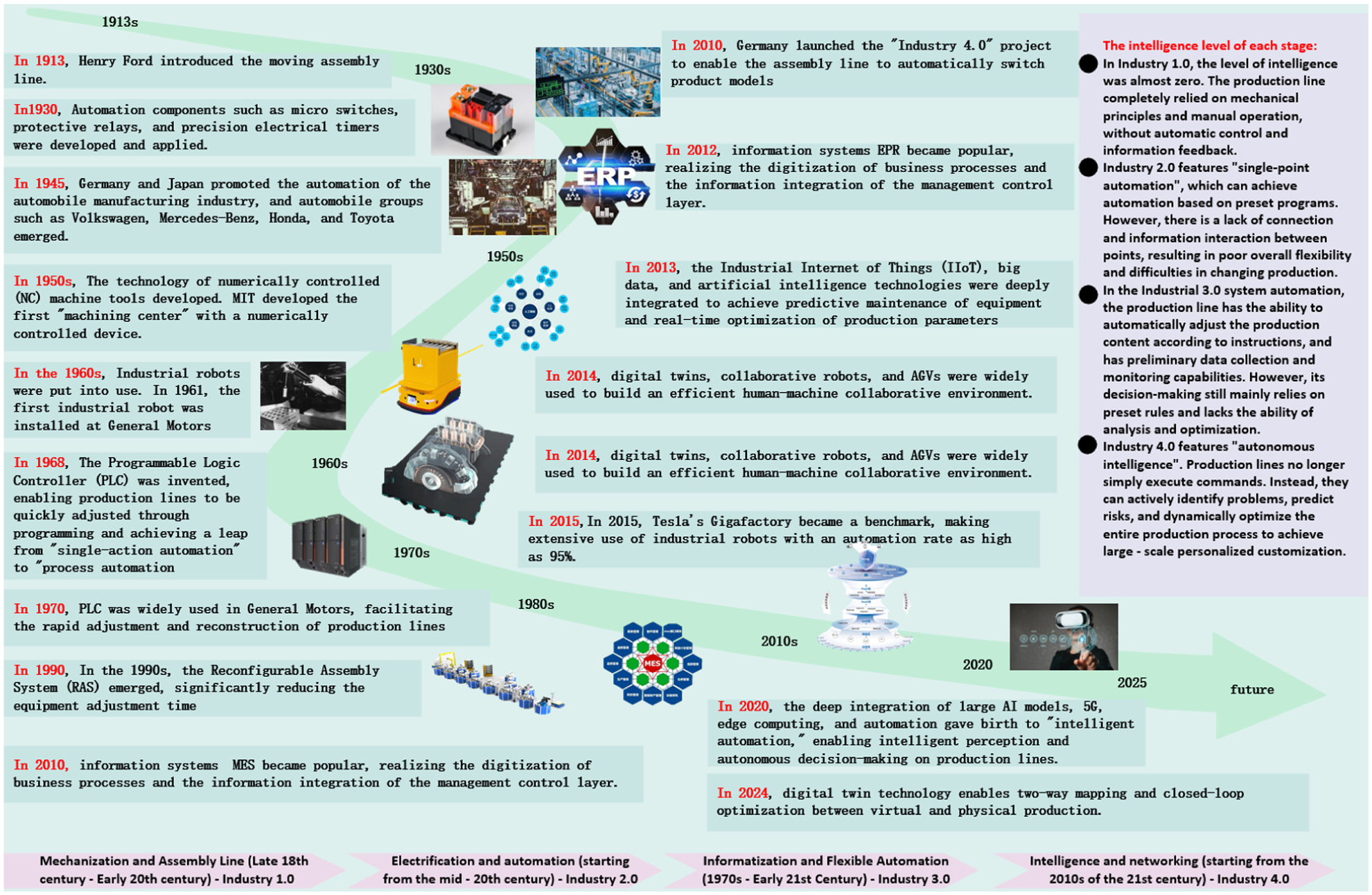
Historical development and evolution process of intelligent production lines.
Research question
This study aims to explore the application of intelligent manufacturing systems in the production line of outdoor units for multi-split air conditioners and determine the available intelligent systems. The research questions are as follows.
The current production line for the outdoor units of the enterprise’s multi-split air conditioners employs 45 workers, who are assigned to each workstation according to the assembly difficulty of the respective parts to maintain a consistent overall production rhythm. After assembly, halogen testing and circuit testing are required, followed by final inspection before dispatch. All of these operations are performed manually, and no intelligent systems have been deployed on this line.
After reviewing the enterprise’s existing manual production lines, data were collected by visiting the outdoor unit assembly lines of specific central air conditioner models, as well as their terminal background processors, to identify potential future implementations of intelligent assembly production lines. 20 Furthermore, to systematically summarize the research progress and technical landscape in this field, this study retrieved and analyzed relevant literature from the Web of Science Core Collection spanning 1992–2025. Eight core research hotspots have been identified, as shown in Figure 2: intelligent manufacturing systems, Industrial Internet of Things, deep learning, machine vision, big data, smart manufacturing, fixture design, and framework. These hotspots cover the entire innovation chain from top-level architecture design to specific enabling technologies. The main research forces are concentrated in China, the United States, and South Korea, and key achievements have mostly been published in high-impact journals such as the Journal of Manufacturing Systems, the International Journal of Advanced Manufacturing Technology, and the Journal of Intelligent Manufacturing.

Literature context diagram of intelligent manufacturing production system.
The academic and industrial circles have carried out extensive explorations around intelligent production lines. At the architectural level, Barenji et al. 21 explored the interlocking control theory of distributed flexible manufacturing systems, providing an important framework for building adaptive production systems. In terms of key enabling technologies, real-time positioning based on machine vision, 22 automatic guided vehicle (AGV) intelligent scheduling algorithms, 23 and production line optimization driven by digital twins have become research focuses.24,25 Li et al. 26 confirmed through cases the significant benefits of industrial robots in enhancing assembly efficiency and consistency. Against the background of intelligent manufacturing, equipment maintenance strategies have evolved from traditional reactive maintenance to predictive maintenance, prescriptive maintenance, and adaptive maintenance. Among them, the dynamic maintenance framework based on the CPS architecture enables real-time perception of equipment status and closed-loop optimization of maintenance decisions. 27 These achievements have laid a solid foundation for the development of this field.
Although existing researches have made progress in areas such as smart production line architecture, robotics applications, and Manufacturing Execution System (MES), a systematic solution that deeply integrates hardware, software, and control is still lacking for complex electromechanical products like multi-split central air conditioners. These products have complex structures and require high assembly precision. Existing studies often focus on single technologies. As a result, they struggle to address the coordination issues caused by automation islands.
To address this, the innovations of this work are mainly reflected in three aspects: (1) it proposes a composite positioning strategy based on “one plane with two pins” and “one plane with two stops,” thereby ensuring precision consistency for complex workpieces during dynamic transport and static assembly; (2) it designs a closed-loop material supply mechanism integrating real-time sensing and dynamic scheduling, enabling autonomous responses to material shortages and precise replenishment; (3) it constructs a three-layer MES management module covering equipment risk analysis, downtime analysis, and improvement proposals, thus achieving vertical integration from data collection to decision-making optimization.
Research objectives and technical routes
Although the general architecture and individual technologies of intelligent production lines have achieved fruitful results, empirical research on integrated solutions for complex electromechanical products such as multi-split central air conditioners is still relatively scarce. Most existing research focuses on the isolated application of macro architectures or specific technologies, lacking systematic exploration of in-depth collaboration among high-precision positioning, flexible fixtures, real-time material supply, and hierarchical control. 28 In particular, the organic integration of hardware, software, and control on an integrated platform to systematically address the problems of automation islands remains a critical shortcoming in current research. 29
As illustrated in Figure 3, this article first reviews the evolution of intelligent production line architectures. Subsequently, it analyzes in detail the research status and development pathways of key enabling technologies, including high-precision positioning and flexible fixtures, robotized assembly, real-time material supply, and intelligent control and management. Through a comparative analysis of existing technical routes, this study summarizes their respective advantages, disadvantages, and applicable scenarios. Finally, in response to current technical integration challenges, this article looks ahead to future key directions such as digital twins and green manufacturing. This article aims to provide researchers in both academia and industry with a clear technological development blueprint, as well as theoretical references and practical guidance for the design and optimization of next-generation intelligent assembly systems.
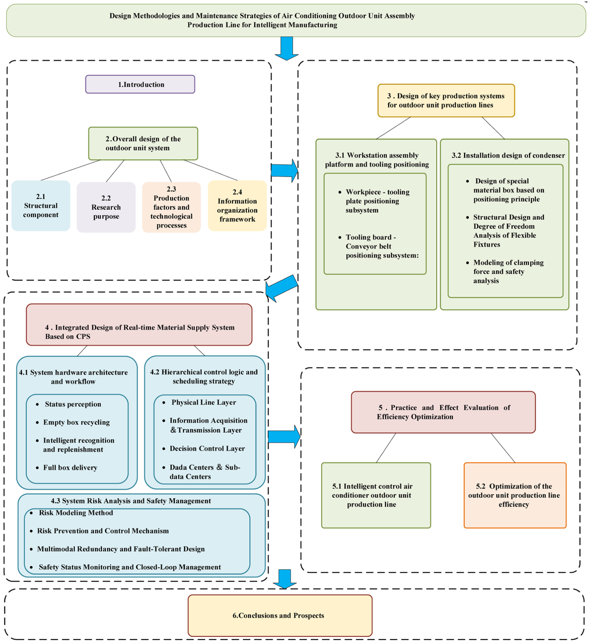
Logical framework of the research methodology.
Research methods
This study adopts a research paradigm of theoretical modeling, system integration, and experimental verification. Initially, guided by the theory of CPS layered architecture, an overall framework for the smart production line is established, encompassing a physical layer, a control layer, and a management layer. Subsequently, to address key bottlenecks in positioning accuracy, material response, and information integration, several models are developed, including a geometric constraint model for high-precision positioning, a clamping force mechanics model for flexible fixtures, and scheduling control logic for AGV logistics. Thereafter, system integration and engineering implementation are carried out in the outdoor unit assembly workshop of central air conditioners. Ultimately, the effectiveness of the proposed solution is quantitatively evaluated through comparative experiments across three dimensions: production efficiency, manpower allocation, and system stability.
Overall design of the outdoor unit system
Structural component design
The outdoor unit of a multi-split air conditioning system is a highly integrated and complex thermal system, with its structural core being a vapor compression refrigeration cycle composed of a variable frequency compressor as the core. 30 This system is mainly composed of a variable frequency drive and control system, a refrigerant pipeline system and an air-side heat exchange system, as shown in Figure 4. Specifically, its structure includes a variable-frequency compressor for refrigerant compression, a finned heat exchanger operating as a condenser or evaporator, a direct current brushless fan driving forced air convection, and an electronic expansion valve for precisely regulating the refrigerant flow rate. To ensure the reliability and efficiency of the system under multiple operating conditions, the outdoor unit also integrates key auxiliary components, such as a four-way directional control valve for switching between cooling and heating modes, an oil separator to guarantee the lubrication of the compressor, and a gas-liquid separator to prevent liquid hammer. 31 All these components are coordinated and controlled by the central main control board. Data is collected through temperature and pressure sensors distributed throughout the system to precisely adjust the compressor frequency, fan speed and valve opening, thereby meeting the complex load requirements when multiple indoor units operate in parallel. They are encapsulated in a sturdy sheet metal housing that has undergone anti-corrosion treatment. 32
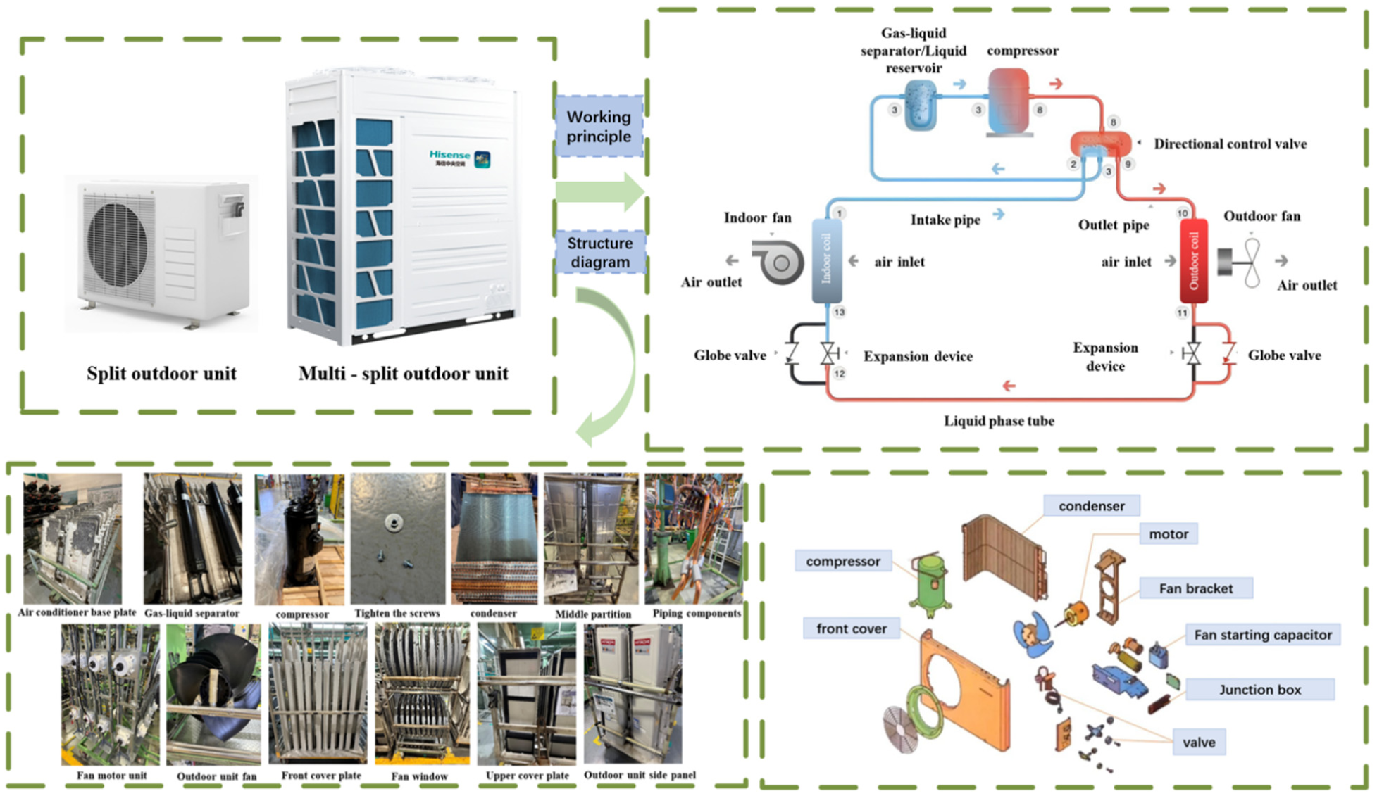
Air conditioner structure composition.
Research purpose
Due to the structural complexity of the outdoor unit components and the high coupling of the assembly process flow, the traditional multi-split air conditioner outdoor unit production lines generally adopt a discrete production mode of manual and dedicated machine. 33 This model has systematic bottlenecks in terms of efficiency, accuracy and flexibility, which seriously restricts the overall performance improvement and intelligent transformation process of the manufacturing system. Specifically, it is manifested in the following aspects:
Firstly, at the level of process equipment, traditional special machines and fixture systems lack adaptive capabilities. Due to the diverse models and significant structural differences of outdoor units, the existing fixtures often need to be frequently replaced and adjusted according to specific workpieces, resulting in long changeover times on the production line and low equipment utilization. Meanwhile, the positioning accuracy is limited by the rigid design of the mechanical structure, making it difficult to meet the requirements of reference consistency for high-precision assembly tasks, resulting in the accumulation of assembly errors and affecting the overall performance and reliability of the machine. 34
Secondly, in terms of material flow and logistics systems, the traditional manual material replenishment method has problems such as delayed response and opaque information. The lack of a real-time linkage mechanism among material inventory status, consumption rate and replenishment demand often leads to production line shutdowns due to untimely material supply, which has become a key bottleneck restricting the overall rhythm and operational efficiency of the production line. In addition, the material traceability capability is weak, making it difficult to achieve full-process visual control from warehousing to workstations.
Thirdly, in terms of information integration and system collaboration, traditional production lines suffer from a lack of effective data interaction channels between equipment units and upper-level management systems, resulting in information islands. Consequently, key information—including production status, equipment operating parameters, and quality data—cannot be collected or fed back in real time. This leads to an opaque production process, delayed scheduling decisions, and inefficient resource allocation, thereby hindering the achievement of data-driven dynamic optimization and closed-loop control.
Fourth, in terms of quality control and process traceability, the traditional model relies on manual inspection and recording, which has problems such as strong subjectivity, poor data consistency, and difficulty in problem location. The lack of online detection and real-time feedback mechanisms leads to the transmission and amplification of defects, increasing after-sales risks and quality costs. 35
Finally, in terms of energy management and green manufacturing, traditional production lines generally lack a detailed monitoring and optimization mechanism for equipment energy consumption. The operating status of key energy-consuming equipment such as motors and pneumatic components is invisible, making it impossible to achieve on-demand energy supply, energy-saving dispatching and energy efficiency assessment. 36 This makes it difficult to meet the current policy requirements for the green and low-carbon transformation of the manufacturing industry and the sustainable development goals of enterprises. In conclusion, the traditional outdoor unit production line needs to achieve the following goals to realize intelligent manufacturing, as shown in Figure 5.
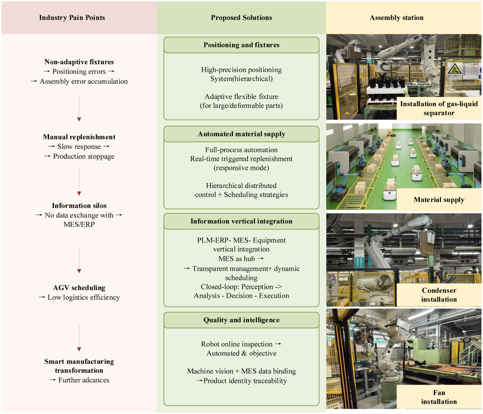
Industry pain points and research objectives.
Figure 5 summarizes the major industry pain points of the traditional production line and the corresponding solution strategies proposed in this study. On the left side, the key limitations are identified. Non-adaptive fixtures cause positioning errors and lead to cumulative assembly errors. Manual material replenishment results in slow response and frequent production stoppages. Information silos prevent effective data exchange between shop-floor equipment and upper-level systems such as MES and ERP. Poor AGV scheduling reduces logistics efficiency. On the right side, the proposed solutions address each of these limitations. A high-precision hierarchical positioning system and an adaptive flexible fixture are designed for large and easily deformable components. A full-process automated material supply system with real-time triggered replenishment is established, adopting a responsive mode instead of traditional predictive or timed replenishment. Hierarchical distributed control and scheduling strategies are implemented. For information integration, a vertical architecture connecting PLM, ERP, MES, and physical equipment is built, with MES serving as the central hub to enable transparent production management and dynamic scheduling. A closed-loop system following the logic of perception, analysis, decision, and execution is realized. For quality and intelligence, robot-based online inspection achieves automated and objective quality control, while machine vision combined with MES data binding ensures product identity traceability. These enhancements collectively transform the traditional production line into an intelligent manufacturing system.
Production factors and technological processes
The multi-split air conditioner outdoor unit production line is an intelligent production line that deeply integrates automated logistics, robot technology and information management systems. The core of its overall solution lies in building a closed-loop empowerment system of “state perception–real-time analysis–autonomous decision-making–precise execution.” The intelligent production line adopts a modular and unitized overall design, and it is equipped with multiple production units arranged according to the planned layout. As the core link of the manufacturing process, the production unit is not only the physical carrier of product processing, but also undertakes the function of the intelligent center of the execution layer, directly related to product quality, production efficiency, and the achievement of annual goals. The production units of the production system are divided into three major categories: manufacturing units, assembly units and testing units. Each unit is internally organized in detail according to production factors and production modules. According to the hierarchical structure shown in Figure 6, the core equipment composition of the intelligent production line platform is as follows: Collaborative manufacturing robot, ground transmission automatic guided vehicles, wireless transmission network base stations and communication modules, various levels of data centers and sub-data centers intelligent display platforms, each production unit integrates machine tools, robots, automation modules, RFID information collection modules, and status Monitoring modules, lighting modules and unit frames. 37
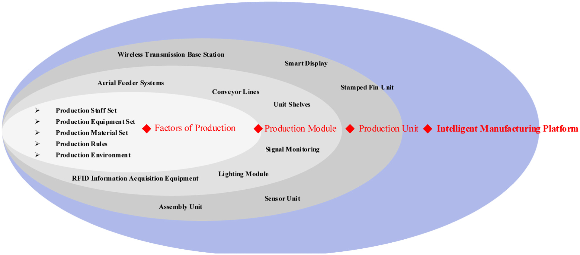
Connection of production factors in the outdoor unit production line.
The layout of the assembly process and the automated workflow of the outdoor unit of the multi-split air conditioner are as follows. When the materials are fully loaded, the central dispatching system issues instructions, and the AGV precisely delivers the materials to the designated assembly unit. Based on the global positioning and recognition of the machine vision system, various specialized robots work collaboratively: The clamping robot is responsible for grasping and assembling core components such as compressors and gas-liquid separators. 38 The screw installation robot integrates a visual servo system to precisely complete tasks such as screw fixation, joint disassembly, and wooden base support installation. Specialized assembly robots rely on the flexible fixtures designed in this paper to perform precise assembly of specific components. 39 The welding robot and the gas detection robot are respectively responsible for pipeline welding and quality inspection processes such as air tightness and halogen leakage. This series layout, as shown in Figure 7 significantly optimizes space utilization through integrated and modular design. Moreover, through the collaborative control among various equipment, it achieves a high degree of continuity and flexibility in the production process, and its efficiency is far superior to that of the traditional isolated production line. 40
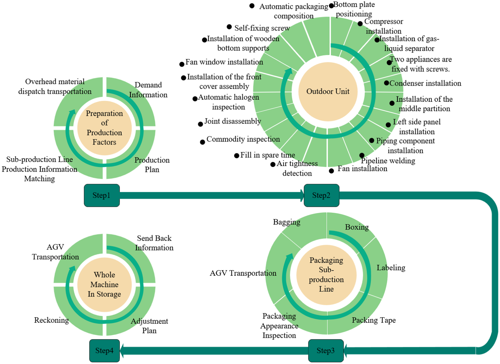
Tandem layout.
Information organization framework
The intelligence of the outdoor unit intelligent production line not only stems from hardware upgrades but also benefits from its underlying software-defined production control architecture. As shown in Figure 8, this architecture adheres to the concept of cyber-physical production systems. Through the vertical integration of product lifecycle management (PLM), enterprise resource planning (ERP), and MES, it achieves global data driven control from order to delivery. 41
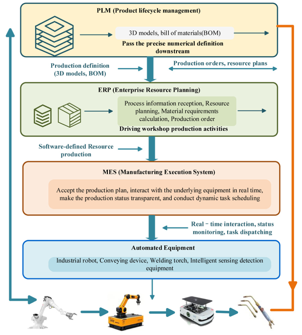
Hierarchical control architecture of the intelligent production line.
As the starting point of the design end, PLM defines the overall product structure through 3D models and bills of materials (BOM), and conveys precise digital definitions downstream. ERP takes in process information, conducts resource planning and material requirement calculation, generates production orders, and drives workshop level production activities. The MES serves as the core connecting the upper and lower levels. It acts as the brain of intelligent control and management. It receives the production plan from ERP and interacts with the underlying automated equipment in real time through industrial network protocols. This achieves transparent management of production status and dynamic scheduling of tasks. 42
To further explore the value of data, the MES system integrates three advanced analysis modules, achieving an elevation from data to decision making. 43 These modules are the equipment risk analysis module, the equipment downtime analysis module, and the product proposal analysis module. The equipment risk analysis module builds on the Maintenance 4.0 dynamic maintenance framework. It establishes a maintenance architecture that includes data acquisition, condition assessment, decision support, and execution feedback. It monitors key equipment parameters in real time, such as vibration, temperature, and current. By combining threshold with trend prediction algorithms, it achieves a shift from condition monitoring to predictive maintenance. Based on equipment health index and remaining useful life prediction, the system can automatically generate maintenance work orders and dynamically adjust production scheduling. This minimizes the impact of unplanned downtime on production efficiency. The equipment downtime analysis module tracks and analyzes equipment downtime and its causes. It reveals the root causes of efficiency losses through visual reports and provides data support for continuous improvement. The product proposal analysis module collects and integrates improvement proposals and design changes during the production process. 44 It promotes the accumulation and reuse of knowledge and experience, building a closed loop of organizational wisdom.
All the data generated by these MES modules are presented to production managers through a centralized visual dashboard, as shown in Figure 9. This dashboard provides a real time overview of the entire production line. The production line overview area displays the status of key equipment such as the discharging machine, weighing machine, ultrasonic cleaning machine, and material cabinet. It also shows environmental parameters including temperature, humidity, carbon dioxide level, and PM2.5 value. The equipment risk analysis module view lists ongoing faults. For each fault, the dashboard shows the device name, alarm level, alarm time, alarm content, and processing status. The production indicator analysis area reports planned output, actual output, overall equipment failure rate, and quality pass rate. The monthly energy consumption section tracks water consumption, power consumption, and PM2.5. A historical production summary over the past year is also provided, showing planned output, actual output, ineffective materials, no signal events, machine failures, and the number of processed versus pending failures. This hierarchical intelligent control architecture, combined with the visual dashboard, ensures efficient allocation of production resources, real time controllability of process status.
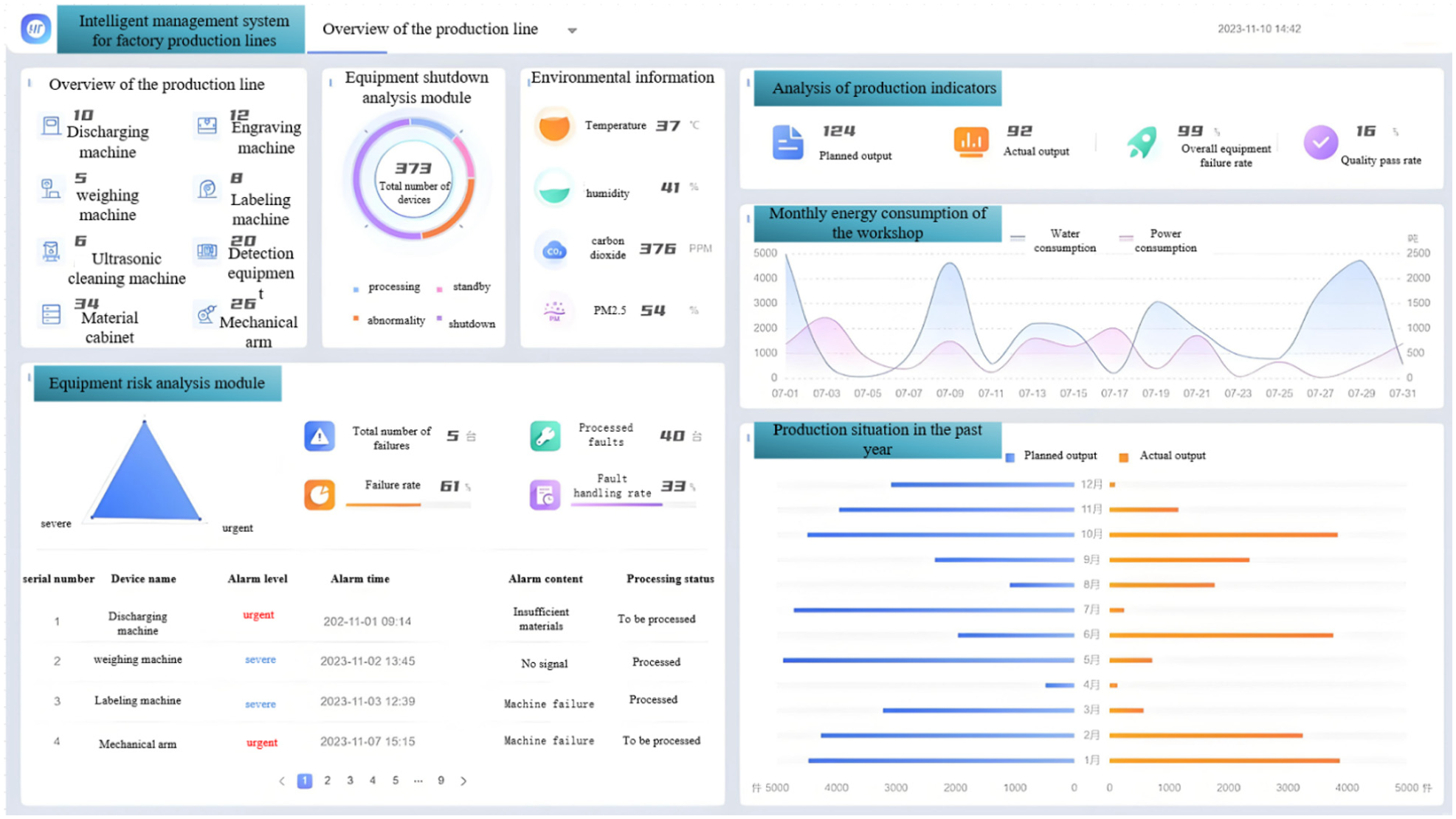
Data visualization.
Design of key production systems for outdoor unit production lines
Workstation assembly platform and tooling positioning
In an automated assembly system, precise positioning and reliable clamping of workpieces during transmission and assembly are the prerequisites for ensuring assembly accuracy and quality. To meet the strict requirements for the consistency of assembly references of each robot assembly unit in the series production line of multi-split air conditioning outdoor units, this section designs a composite positioning system based on the “one side, two pins” principle, and elaborates in detail on the positioning and clamping mechanisms. 45
To ensure posture stability during transmission and precise repeat positioning upon arrival at the workstation, a hierarchical positioning strategy was designed, as shown in Figure 10. Its core consists of the workpiece–tooling plate positioning subsystem and the tooling plate–conveyor belt positioning subsystem. 46
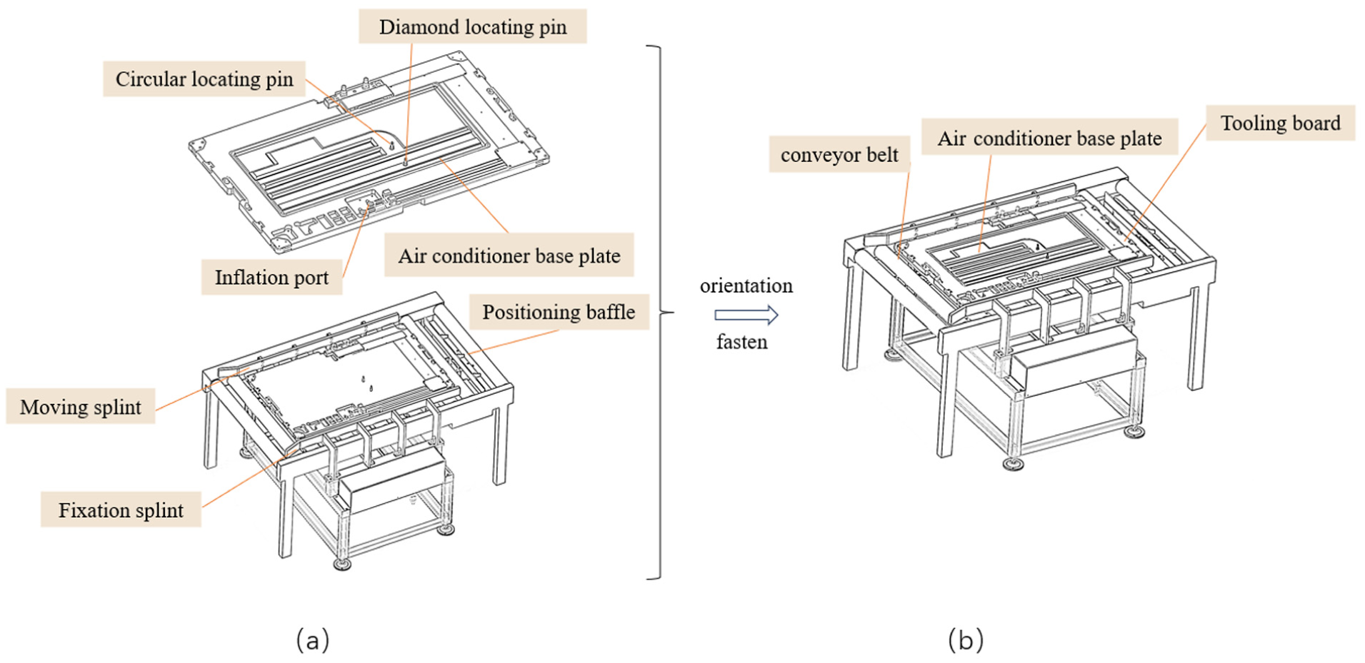
Tooling positioning and layout.
Workpiece–tooling plate positioning subsystem
The subsystem adopts the “one side, two pins” positioning principle to achieve complete positioning of the outdoor unit assembly of the air conditioner. As shown in Figure 10, the primary positioning reference is established by the contact between the lower surface of the air conditioning base plate and the upper positioning reference surface of the tooling plate, which constrains translation along the Z-axis as well as rotations about the X- and Y-axes, thereby restricting three degrees of freedom.
The secondary positioning reference consists of a cylindrical positioning pin and a rhombic positioning pin mounted on the tooling plate. These pins respectively form a clearance fit with the corresponding positioning holes on the air conditioning base plate. The cylindrical pin restricts translation of the assembly along the X-axis and Y-axis, thereby limiting two degrees of freedom. The rhombic pin, owing to its freedom in the direction perpendicular to the line connecting the two pins, primarily restrains rotation about the Z-axis, thus avoiding over-positioning.
Through the above-mentioned coordination, this subsystem completely restricts the six degrees of freedom of the workpiece in space, establishing a unified and precise reference for all subsequent assembly actions.
Tooling board–conveyor belt positioning subsystem
When the tooling plate carrying the workpiece is conveyed to the target station, a secondary precise positioning operation is required to eliminate any cumulative errors that may have arisen during transmission. The corresponding positioning and clamping mechanism functions as follows. For longitudinal positioning, the positioning baffle at the front end of the conveyor belt is lifted upward by a cylinder and contacts the lateral positioning surface of the tooling plate, thereby effectively restricting its movement along the conveying direction. For lateral positioning, the other side of the tooling plate remains in continuous contact with the fixed baffle on the side of the conveyor belt, thus constraining motion in the direction perpendicular to conveyance. Finally, for clamping, a pneumatic push plate located on the side of the conveyor belt is actuated by a bottom cylinder, applying clamping force to the tooling plate from the opposite side so that it is pressed tightly against the fixed baffle, ultimately achieving complete fixation at the workstation. This hierarchical positioning system ensures that the workpiece maintains a controlled and precise position throughout the entire process, from dynamic transport to static assembly, thereby providing a foundation for high-precision robotic operation.
Installation design of condenser
In automated assembly, achieving stable, non-destructive grasping and precise positioning of sheet metal parts that are large in size and prone to deformation is both a key requirement and a major challenge. Traditional manual handling is inefficient and poses safety and quality risks. To address this issue, this section presents a flexible grasping system that integrates a dedicated material box with an adaptive pneumatic fixture, and provides an in-depth analysis of its positioning principle, structural degrees of freedom, and clamping mechanic model.
Design of special material box based on positioning principle
To achieve rapid and precise grasping of the condenser by the mechanical hand, it is first necessary to constrain and standardize its posture during the material feeding process. This study designed a special material box based on the positioning principle of “one side and two pins,” and its structure is shown in Figure 11.
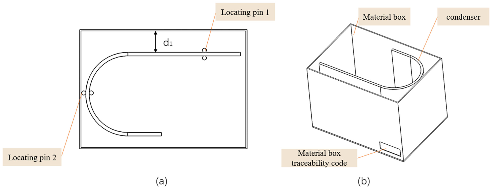
Structure diagram of condenser material box: (a) Top view of condenser with locating pins and (b) Isometric view of integral material box.
To pre-position the condenser inside the material box, this design restricts its degrees of freedom within the horizontal plane, thereby enabling the end effector of the robotic arm to grasp it with a repeatable trajectory. The positioning mechanism operates as follows. The main positioning surface is formed by the contact between the bottom surface of the condenser and the upper surface of the material box, which constrains translation along the Z-axis as well as rotations about the X- and Y-axes, thus limiting three degrees of freedom. The line positioning element consists of positioning pin 1, which contacts the corresponding side of the condenser and restricts its movement along the Y-axis. The point positioning element, positioning pin 2, contacts the other side of the condenser and restricts its movement along the X-axis. With this design, all uncertainty of the condenser’s motion in the horizontal plane within the material box is completely eliminated, while only the vertical translational degree of freedom is retained for grasping. Consequently, a stable and consistent initial pose is provided for subsequent robot grasping.
Structural design and degree of freedom analysis of flexible fixtures
To achieve the automatic transfer and installation of the condenser from the material box to the assembly station, this paper designs an adaptive flexible fixture based on pneumatic drive, whose structure is shown in Figure 12.
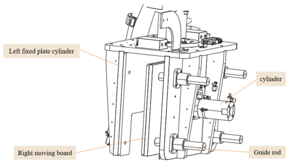
Condenser fixture structure.
This fixture adopts a symmetrical clamping mechanism driven by a single cylinder. The working process is as follows: The mechanical vision system first identifies and locks the coordinates of the condenser; Subsequently, the pneumatic circuit drives the piston rod of the cylinder to move, pushing the right movable clamping plate to move synchronously toward the left fixed clamping plate, thereby achieving the clamping and holding of the workpiece. 34 This pneumatic system is designed with an overflow valve, By setting the upper limit of the system pressure, the fixture can undergo adaptive deformation after contact with the workpiece, thereby being compatible with workpieces within a certain size range and achieving flexible grasping.
The degree of freedom analysis of this clamping device is a key step to verify its motion certainty and design rationality. According to the principles of mechanics, its degrees of freedom can be calculated by the Grubel formula (1)

Among them, F1 represents the degrees of freedom of the mechanism, n is the number of moving components, PL is the number of low pairs, and PH is the number of high pairs. After analysis and calculation, the degree of freedom of this condenser fixture device is 1, which conforms to the design of a single cylinder input drive, and its movement is controllable.
Modeling of clamping force and safety analysis
To ensure that the fixture can reliably grasp the workpiece under dynamic working conditions without slipping or getting damaged, the clamping force must be precisely calculated and set. 47 Based on the principle of static equilibrium, a force model as shown in Figure 12 is established.
Suppose the material is in a static equilibrium state and complex elastic deformation is ignored. To prevent the workpiece from sliding down under the combined action of gravity G, inertial force Fi and other external interfering forces Fe, the total frictional force Ff provided by the fixture should meet the following conditions:

Among them, the frictional force Ff

µ is the coefficient of friction, and Fc is the normal clamping force provided by the single-sided clamping plate.
Therefore, to ensure safe grasping, the minimum clamping force Fc required can be obtained from formulas (2) and (3) as follows:

To address unmodeled dynamic factors and fluctuations in operating conditions, a safety factor K (K > 1) is introduced. From formulas (2)–(4), the designed clamping force Fc can be obtained as follows:

Based on this clamping force, the air pressure P required to drive the pneumatic cylinder can be further calculated:

Among them, F represents the total load force that the hydraulic cylinder needs to overcome, and a represents the effective action area of the hydraulic cylinder. This mechanical model provides a theoretical basis for the selection of fixture drive components and the setting of system pressure, ensuring the safety and reliability of the grasping process in principle. 48
Integrated design of real-time material supply system based on CPS
The stable and efficient operation of intelligent production lines is highly dependent on continuous and timely material supply. The traditional manual feeding method has become a bottleneck, restricting the overall efficiency of the production line, due to response delay and information opacity. 49 To solve this problem, this section designs and implements a real-time material replenishment system based on the CPS architecture. This system integrates AGV, machine vision and 5G communication technologies to build a closed-loop logistics control system that combines “perception–decision-making–execution.”
System hardware architecture and workflow
The hardware integration architecture of this system aims to achieve full-process automation of material replenishment. Its core consists of a mobile handling unit, a fixed-point execution unit, and a perception and decision-making unit.
The mobile handling unit serves as the dynamic logistics carrier of the system, responsible for transporting material boxes between the warehouse and assembly stations. As shown in Figure 13, the fixed-point execution unit is deployed in the central warehouse. It consists of an industrial robot, a dedicated material box fixture, and a precision servo slide that drives the robot along the X-axis. This design significantly expands the robot’s working range, enabling it to serve a linearly arranged material warehouse. 50
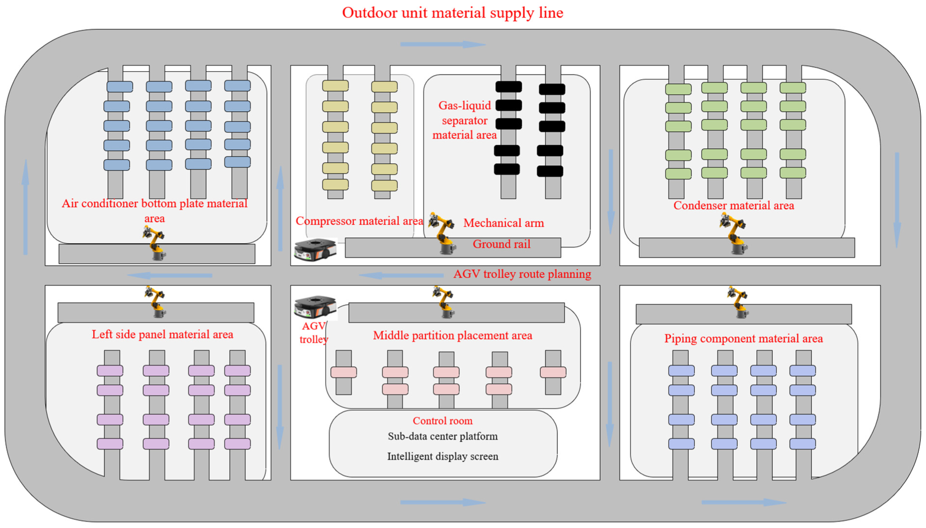
Material supply line planning diagram.
Perception decision-making unit: As the eyes of the system, it is deployed at each assembly station and the central warehouse, used for real-time identification of the codes of material boxes and the vacant status of materials inside them. 51 Based on the above hardware, its automated workflow is as follows:
(1) Status perception: The machine vision system at the workstation continuously monitors the status of the material box. When a missing part is identified, the system triggers an alarm and sends a replenishment request to the central dispatching system via a low-latency 5G industrial network. 52
(2) Empty box recycling: AGV carts receive instructions and go to the corresponding workstations to carry the empty material boxes back to the central warehouse.
(3) Intelligent recognition and replenishment: The visual system at the warehouse end recognizes the numbers of the returned empty material boxes. The material replenishment robot then moves to the corresponding silo driven by the slide table, grabs the full material box and performs precise feeding. 53
(4) Full box delivery: After the replenishment is completed, the AGV trolley, in accordance with the instructions of the dispatching system, delivers the fully loaded material boxes to the requested workstations, thus completing the entire replenishment cycle.
Hierarchical control logic and scheduling strategy
The intelligent core of this supply system lies in its hierarchical distributed control logic, as illustrated in Figures 14 and 15, which effectively coordinates the operations of workstation terminals and the central warehouse.
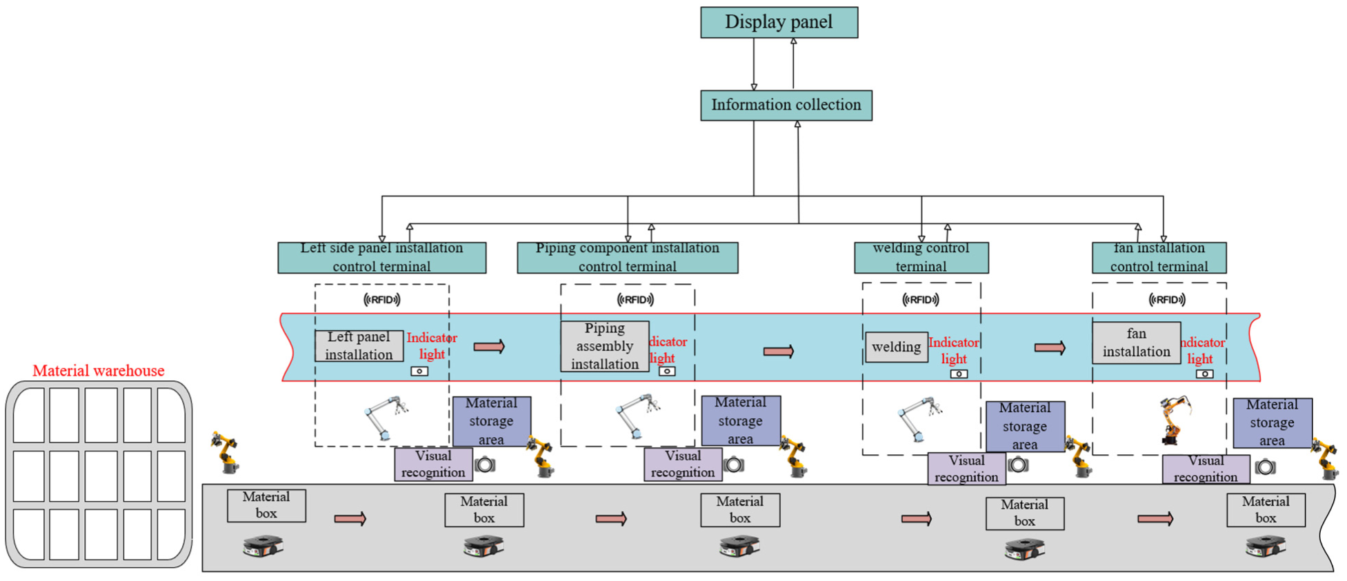
Workstation terminal hierarchical control logic diagram.
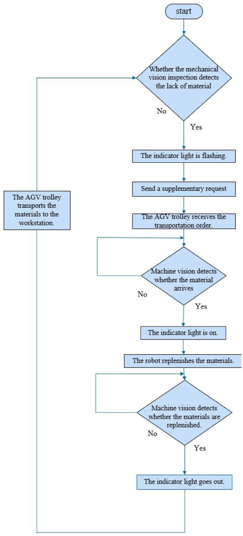
Material supply logic control diagram.
At the workstation level, each assembly workstation functions as an intelligent node equipped with local perception via visual inspection and communication capability through a 5G network for reporting. The control logic focuses on monitoring local status and initiating requests, following a simple principle of detection, alarm, and request. 54
At the warehouse level, the central warehouse serves as the dispatching hub of the system. Its control logic covers the entire chain of receiving requests, identifying boxes, executing material replenishment, and confirming completion. Status indicator lights, which can be turned on or off, provide intuitive system status feedback to on-site operators. 55
At the system level, the terminal intelligent warehouse management system, acts as the highest decision-making level and plays the role of the brain. It monitors the real-time location and status of all materials, optimizes the distribution routes of AGVs, and presents the dynamic real-time status of the entire material flow on a data monitoring screen, thereby achieving visual and transparent management of global logistics. 56
By delegating decision-making authority to edge nodes such as workstations and warehouses while maintaining global coordination through the central system, this supply system achieves rapid response and efficient resolution of production disturbances, for instance material shortages, thereby significantly enhancing the robustness and continuity of the production line. 57
System risk analysis and safety management
Risk modeling method based on FTA-ETA
In highly automated intelligent manufacturing environments, production systems are tightly coupled. They consist of multiple subsystems. Examples include industrial robots, AGV, machine vision systems, and MES. This coupling brings significant efficiency gains. However, it also makes the system more sensitive to local failures. A single device failure, communication interruption, path conflict, or recognition error can spread along system links, This can trigger cascading failures. It may cause full-line shutdowns or quality accidents. Therefore, while efficiency improvements are being pursued, systematic risk analysis and safety management mechanisms must be established to ensure the reliability and safety of the production process.
To systematically identify and control potential risk sources, this study adopted a system dynamics risk analysis method. It combined fault tree analysis (FTA) and event tree analysis (ETA). Based on this, a risk assessment model suitable for intelligent production lines was established. FTA is used to identify root causes of system failures from top to bottom. Unplanned production line shutdown was taken as the top event, and its triggering factors were broken down layer by layer. 58
These factors fall into three main categories, namely device layer failures, logistics layer failures, and control layer failures. 59 As shown in Figure 16, device layer failures include robot servo motor overload, pneumatic component jamming, and vision camera communication timeout. Logistics layer failures include AGV path deadlock, low battery power, and collisions caused by blind spots in lidar perception. Control layer failures include communication interruptions between the MES and PLC, 5G network delays exceeding thresholds, and scheduling algorithms falling into local optima. 60 Through a qualitative FTA, the structural importance of each basic event can be clarified, thereby providing a priority basis for the deployment of subsequent protective measures.
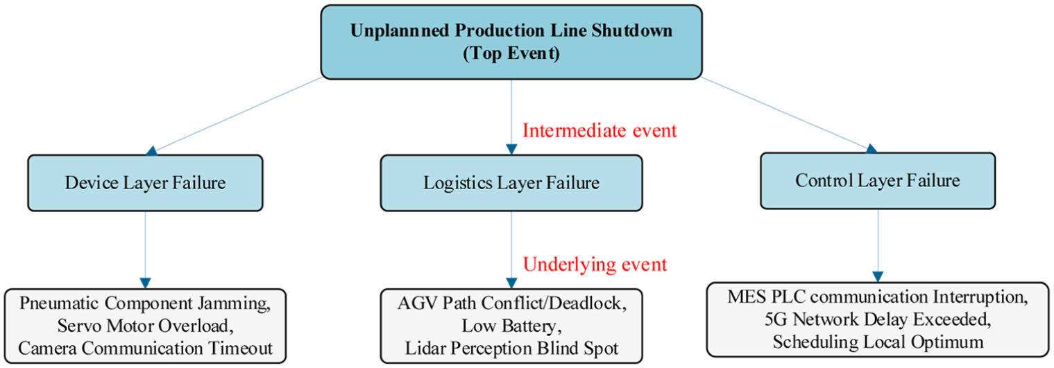
FTA risk assessment model framework diagram.
As shown in Figure 17, ETA is employed for forward projection to track system evolution following an initial event while considering the effects of different protective measures. Taking conflict of AGV path as an example initiating event, the branches of its event tree include the following scenarios. The central scheduling system identifies the conflict in advance and triggers dynamic replanning, after which the system returns to normal operation. Alternatively, identification fails but the AGV’s own obstacle avoidance mechanism activates, allowing the system to operate at reduced speed and recover after manual intervention. If both identification and obstacle avoidance fail, a collision occurs, which triggers a safety shutdown and causes a production line interruption. ETA enables quantitative evaluation of the occurrence probability of each branch and identifies weak links in existing protective measures, thus providing a quantitative basis for redundancy design and emergency mechanisms.
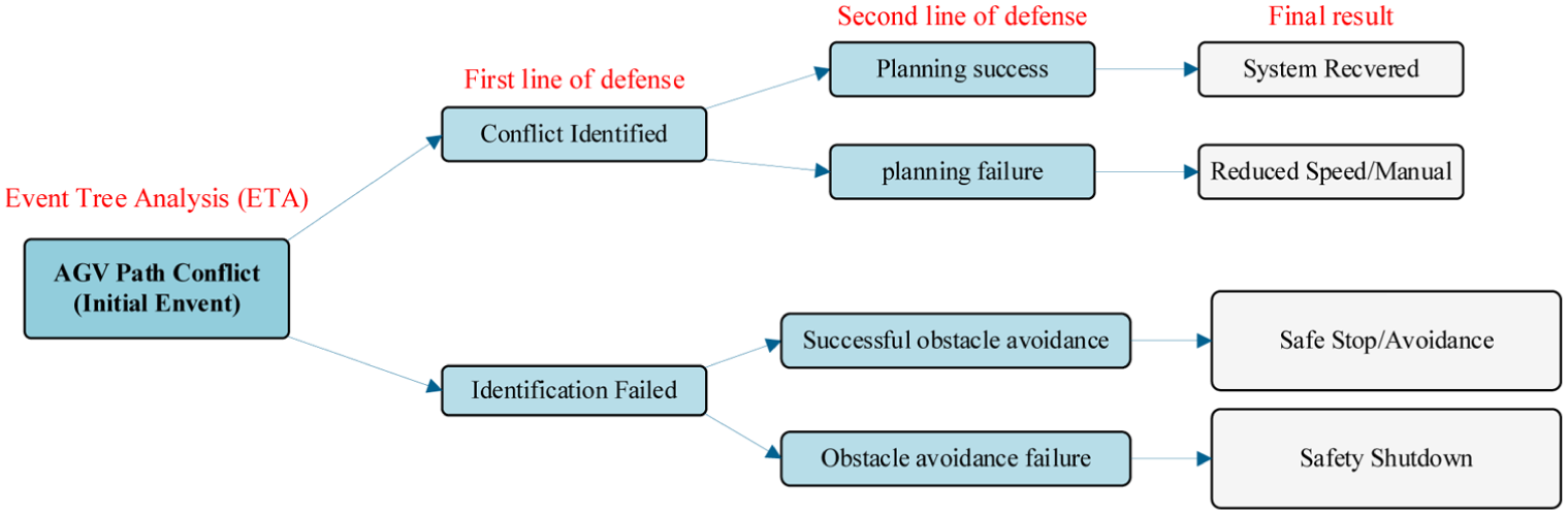
ETA risk assessment model framework diagram.
Risk prevention and control mechanism for AGV logistics system
The AGV system acts as the artery of the production line, and its operational stability directly affects the continuity of material supply. To address typical risks in AGV operation, this study developed two key mechanisms, a priority scheduling mechanism and a dynamic collision avoidance algorithm, as illustrated in Figure 18.
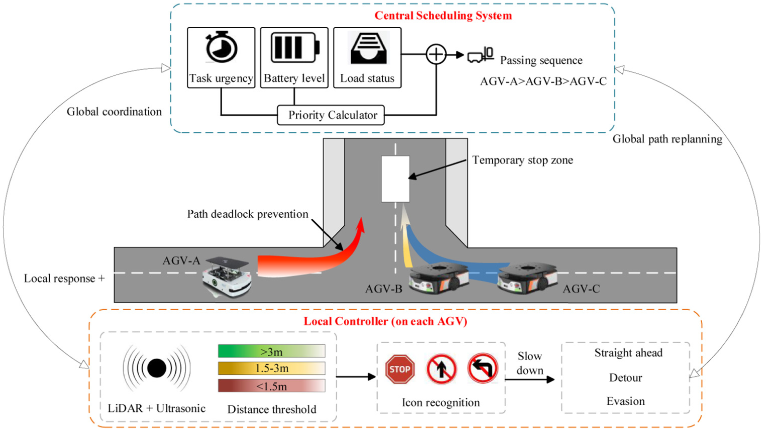
Schematic diagram of AGV priority scheduling and dynamic collision avoidance mechanism.
The priority scheduling mechanism operates based on three core factors “task urgency,” current battery level, and load status. It dynamically assigns passage priority to each AGV, especially when multiple AGVs have crossing paths or must pass through narrow sections. In such scenarios, the central scheduling system collects real-time data—including each AGV’s position, speed, and task status—via real-time communication, and determines the passage order according to priority rules, thereby preventing path deadlock at the source. Additionally, the system designates temporary stop zones to accommodate low-priority AGVs when conflicts arise, further enhancing the robustness of global coordination. If a potential deadlock is detected, the central scheduler initiates global path replanning to dynamically adjust routes for the involved vehicles.
The dynamic collision avoidance algorithm is implemented in the local controller of each AGV. Each AGV is equipped with lidar and ultrasonic sensors to perceive surrounding obstacles in real time. Based on the measured distance to another AGV or a person, the controller operates in three zones: when the distance exceeds 3 m, the AGV proceeds straight ahead; when the distance falls between 1.5 and 3 m, the AGV automatically slows down; when the distance is below 1.5 m, the AGV executes an evasive maneuver, which may include stopping, temporarily detouring, or other evasive actions. Simultaneously, the local obstacle avoidance action is reported to the central scheduling system through the 5G network, triggering global path replanning and preventing new conflicts that might arise from a single vehicle’s evasive maneuver. 61
This two-layer mechanism follows the logic of local response and global coordination and has significantly improved the robustness of AGV clusters under complex working conditions.
Multimodal redundancy and fault-tolerant design for visual recognition systems
The visual recognition system is the foundation for robots’ precise grasping and assembly. Its recognition errors can cause serious problems, including grasping failures, workpiece damage, and even safety accidents. To improve the reliability of the visual system, this study introduced a multimodal sensing redundancy architecture, as illustrated in Figure 19.
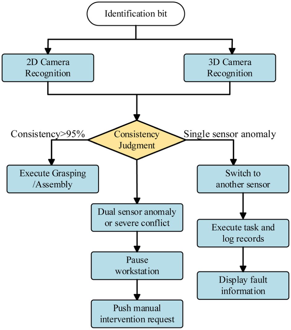
Flowchart of redundancy and fault-tolerant mechanism for multimodal visual recognition.
As shown in the figure, the process begins at the identification bit, where the workpiece is positioned for inspection. The system deploys two types of sensors simultaneously—2D industrial cameras and 3D laser profilers. The 2D camera handles two core tasks: identifying workpiece models and performing rough position positioning. The 3D laser profiler is responsible for precise measurement of workpiece posture and edge contours. Data from the two types of sensors is fused and processed in the industrial control computer. 62
At the consistency judgment stage, the system compares the recognition results from the two sensors. Two working scenarios are defined. In the first scenario, the consistency of the two recognition results is above a preset threshold. 63 In this case, the system executes subsequent actions normally, executing grasping or assembly. In the second scenario, the consistency falls below the threshold, or the recognition confidence of a single sensor drops. In this case, the system automatically triggers a fault-tolerant mechanism.
The fault-tolerant mechanism has two response modes. Mode one applies when only one sensor is abnormal, the system automatically switches to the other sensor, uses the normal sensor to complete the current task, and records an abnormal log. 64 Mode two applies when both sensors are simultaneously abnormal, or when the two recognition results are in serious conflict. In this case, the system immediately pauses the workstation, pushes a manual intervention request via the MES interface, and displays the sensor status and suspected fault causes for operator action. 65
This fault-tolerant mechanism effectively prevents defect propagation caused by visual misrecognition and, at the same time, provides accurate fault location information to support subsequent equipment maintenance. 66
MES-based safety status monitoring and closed-loop management
To achieve full process closed loop risk management, this study embedded a new module into the MES system, namely a safety status monitoring dashboard. As illustrated in Figure 20, this dashboard acts as the visual entry point and decision support tool for safety management. It collects real time status data from the device layer, sensing layer and control layer, and presents the data in three categorized views. 67
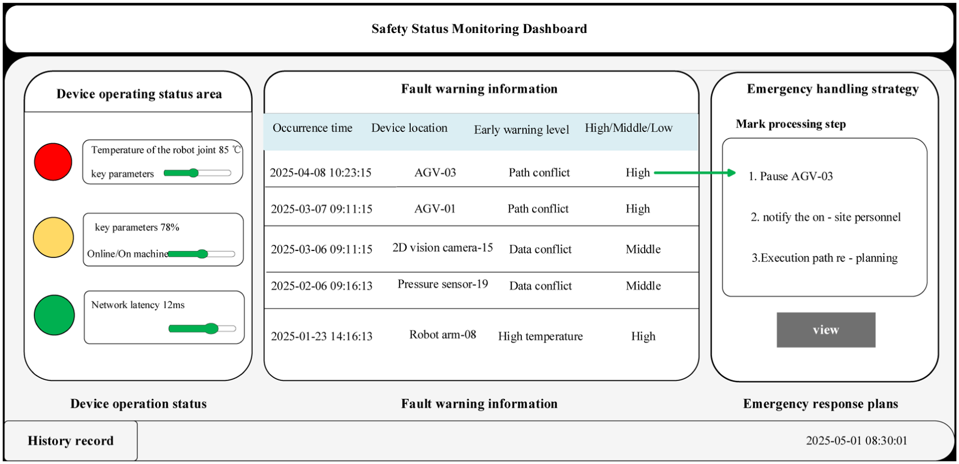
Schematic diagram of the safety status monitoring dashboard interface based on MES.
Device operation status area
The system uses three colors to mark each device’s status. Red represents online, yellow represents offline and green represents fault. Key parameters are also displayed, such as robot joint temperature, AGV battery level, and network latency. 68
Fault warning information
When monitored parameters exceed preset thresholds, for instance motor temperature above 85°C or visual recognition confidence below 80%, the system automatically generates a warning entry. As shown in the dashboard’s fault table, each entry includes the occurrence time, the device location, the fault type, and the early warning level. Historical fault records can be traced for root cause analysis. 69
Emergency response plans
For common fault types, for example AGV deadlock or visual communication timeout, the system provides built in standard disposal processes. When a fault is selected, the dashboard displays the corresponding handling steps. An example is “1. Pause AGV-03; 2. Notify on site personnel; 3. Execute path re-planning.” Operators can view these steps with one click, which significantly shortens the emergency response time.
With this dashboard, production managers can grasp the overall safety situation in real time, trace historical fault records, and analyze the root causes of repetitive problems. This mechanism forms a closed loop safety management process that follows the logic of “risk identification, dynamic response, status recovery.” It realizes the transformation from passive response to active prevention. 70
Practice and effect evaluation of efficiency optimization
To scientifically evaluate the performance of the proposed intelligent production line, this section conducts a comparative study with traditional manual production lines through rigorous data analysis. The verification focus is concentrated on three core dimensions: production efficiency, resource utilization rate and system stability. 71
Intelligent control air conditioner outdoor unit production line
Compared with the traditional manual assembly production line, the intelligent control multi-split air conditioner outdoor unit production line has greatly improved the assembly efficiency in each assembly process. The data center has deployed a feature point recognition system, which integrates 3D welding contour scanning, data interface contour scanning, and leakage point contour scanning. It integrates performance testing, safety testing, and appearance testing into the intelligent control of the multi-split air conditioning outdoor unit production line. 72 The specific assembly process of the intelligent control multi-split air conditioner outdoor unit production line is as follows, as shown in Figure 21:
S1, placement of the air conditioner floor: Before placing the air conditioner under the floor, it is necessary to identify the positioning pins on the tooling board, and complete the positioning of the air conditioner floor under the floor through the positioning pins.
S2, compressor installation: Before installing the robotic arm, a mechanical vision system is required to identify the locating pins of the compressor.
S3, installation of gas-liquid separator
S4, screw fixation: After the screws are fixed at the fixed coordinates, the positioned compressor and gas-liquid separator are fixed.
S5, condenser installation: The condenser is installed by a mechanical arm.
S6, installation of the middle partition: The internal space of the air conditioner is divided into two parts by the middle partition for installing pipelines and fans.
S7, piping assembly installation: The piping assembly is initially installed through robot and mechanical vision recognition to provide conditions for subsequent welding.
S8, fan installation: Install the fan assembly on the other side of the middle partition.
S9, pipeline welding: Weld the piping components after installation to prevent gas leakage.
S10, control board installation: The control board is installed above the pipeline section by a robot.
S11, side panel installation: Complete the initial installation of the outdoor unit of the air conditioner.
S12, vacuum evacuating: The air conditioning pipe interface is identified by mechanical vision, and then the charging pipeline is connected to the outdoor unit by a mechanical arm to complete the charging.
S13, air tightness test: Check whether there is any gas leakage in the outdoor unit of the air conditioner.
S14, disassembly of the connector: Remove the end of the outdoor unit with the cover and check whether the halogen level at the interface is too high.
S15, halogen detection: Detect for any gas leakage.
S16, rear cover plate installation.
S17, installation of air conditioning guard mesh.
S18, place the wooden base support.
S19, fixed with screws.
S20, automatic box packing.
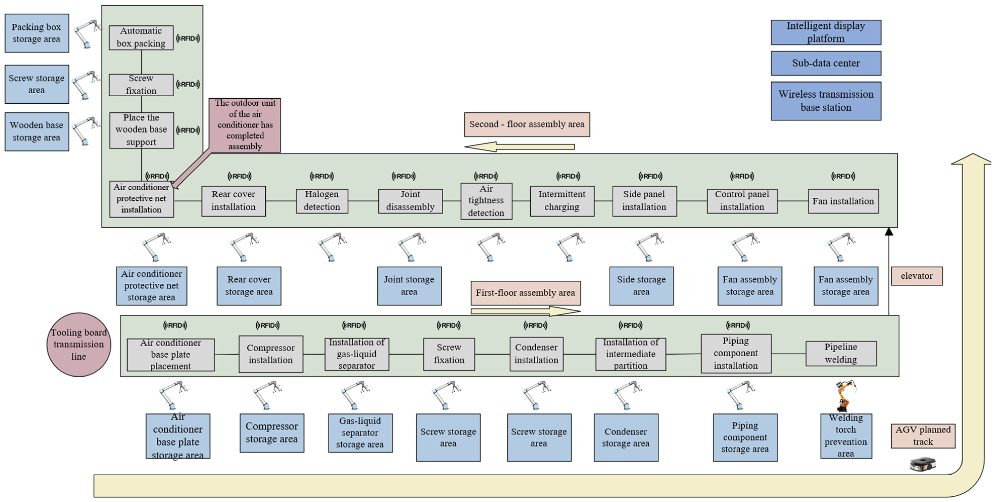
Diagram of outdoor unit production line based on intelligent control.
After the S20 is completed, the outdoor unit of the air conditioner is assembled and transported to the warehouse by an AGV trolley for storage, waiting for system allocation.
Optimization of the outdoor unit production line efficiency
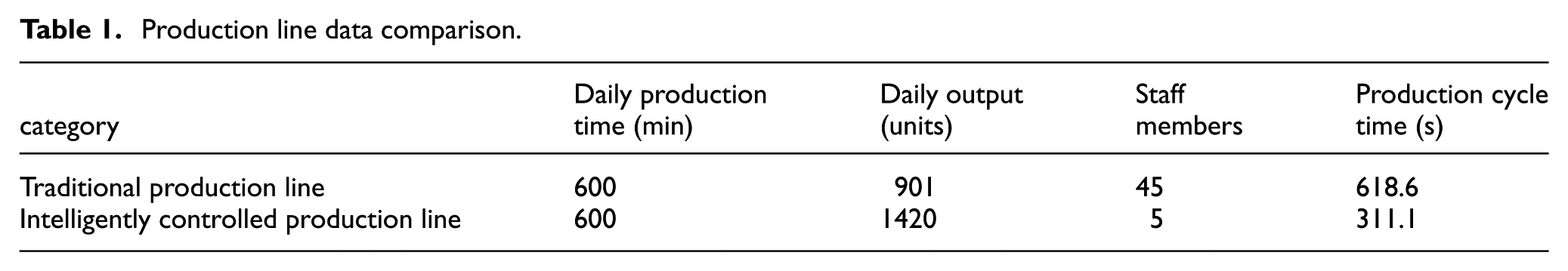
Through the comparative analysis of specific production data, the practical application effect of the multi-split air conditioner outdoor unit production line case based on intelligent control and management was verified. In this study, the outdoor unit of the multi-split system of central air conditioning of a specific model (HUR-90KF/ YDZBpPd-1) was selected as the test object, and the data was collected from the background processor of the production line terminal. 73 Compared with traditional production lines, the intelligent control multi-split air conditioner outdoor unit production line significantly shortens the production cycle and reduces the defect rate during the production process. 74 It demonstrates advantages in six dimensions: production efficiency and cycle time, human resource allocation, assembly accuracy and quality consistency, production flexibility and corresponding capabilities, information transparency and control capabilities, and intelligent material flow and logistics. 75 The multi-split central air conditioning production line has developed into a provincial key industry. Table 1 shows the gain effect of the multi-split production line based on intelligent control, and Figure 22 presents a visual chart of the production line transformation effect. 76
Production line data comparison.
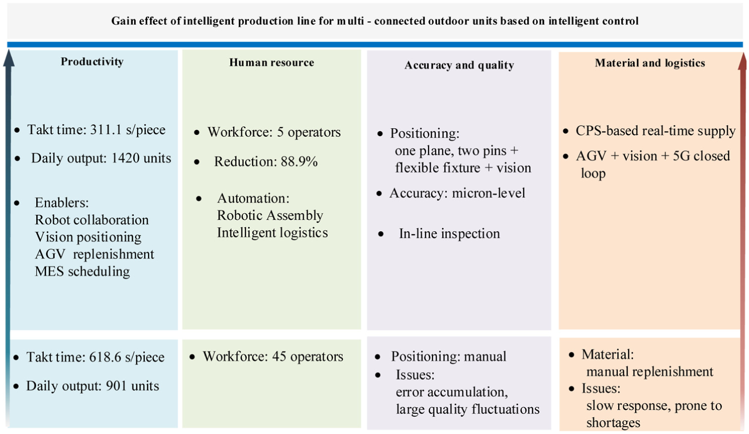
Gain effect diagram.
Through the daily output of a single product, the efficiency of the intelligent production line has been increased by 57%.The deep-seated reasons for the 57% efficiency improvement can be summarized into three aspects: the elimination of time through the positioning system and flexible fixtures; the real-time material response mechanism based on vision and AGV, which cuts material waiting time from an average of 28 s per unit on traditional lines to 5 s per unit; and the real-time data exchange between the MES and shop-floor equipment, which enable s dynamic cycle time matching. Consequently, the number of personnel has been reduced from 45 to 5. These five workers are mainly responsible for system monitoring, anomaly handling, and process parameter adjustments, and are no longer directly involved in assembly operations. 77 This change reflects a shift from a labor-intensive model to a knowledge-intensive one, and embodies the human-machine substitution characteristic of smart manufacturing. 78
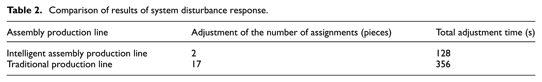
Dynamic factors existing in the actual production environment, such as AGV avoidance, can cause delays in the production line, as shown in Table 2. Therefore, one of the key focuses of future work is to further optimize the cluster scheduling algorithm of AGVs to minimize the impact of such uncertainties and thereby more fully tap the energy-saving potential of the production line. 79
Comparison of results of system disturbance response.
The average production cycle time of the traditional production line is 618.6 s per piece. Its longer cycle time mainly results from manual loading and unloading, clamping and various delays. Intelligent production line cycle time calculation: Based on the time research method, the single-station assembly time and auxiliary time, including machine vision recognition, material grasping and movement, of each station on the intelligent production line were precisely measured and summarized as shown in Table 1, and the average production cycle time was obtained as 311.1 s per piece. Data shows that while the intelligent production line has increased production efficiency by 57%, it has also reduced the number of workers on the production line by 89%. This fully validates the dual advantages of the proposed integrated solution in optimizing human resources to the extreme and breaking through efficiency bottlenecks. 80
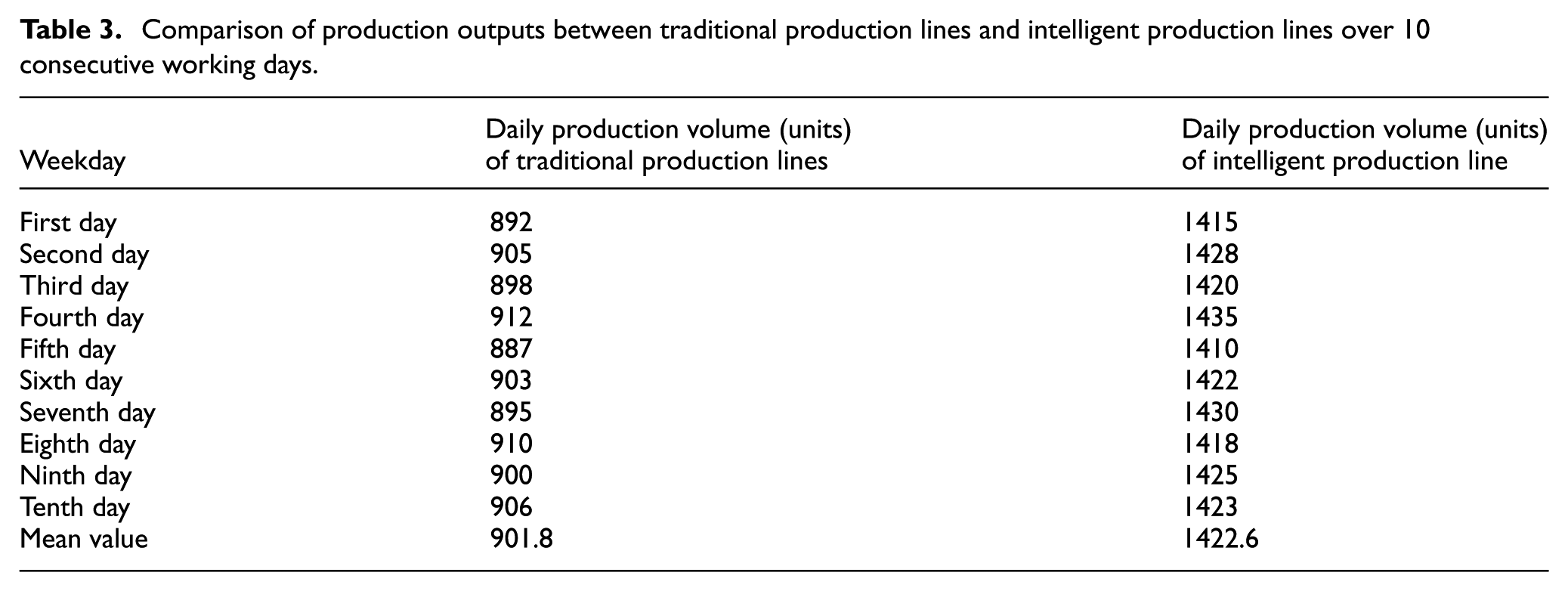
As shown in Table 3, to verify the statistical significance of the results, an independent samples t-test was conducted on the daily output data from the traditional and smart production lines. Output data from 10 consecutive working days were selected for analysis. The results show a significant difference in the means between the two groups. This indicates that the efficiency improvement of the smart production line is statistically significant. In addition, the article conducted cross-model validation for different models within the same product series, such as HVR-850W/SM and HVR-1120W/SM. The results show that the efficiency improvement remains stable between 56% and 59%. This demonstrates the applicability of the proposed solution across different models. 81
Comparison of production outputs between traditional production lines and intelligent production lines over 10 consecutive working days.
As shown in Table 4, to evaluate the robustness of the system under different configurations, the article designed three comparison scenarios:
(1) Introducing only robots while retaining manual logistics.
(2) Introducing only AGV logistics while retaining manual assembly.
(3) The integrated solution proposed in this paper.
Comparison of production line performance under different system configurations.

Experiment results show that the overall efficiency improvement of Scenario 3 is significantly better than the two partial automation scenarios. This verifies the necessity of integrated innovation in hardware, software, and control. 82 The current system has achieved real-time data collection and visual monitoring of production data. This lays the data foundation for building a digital twin model. 9 However, a complete digital twin requires two-way real-time synchronization and closed-loop optimization between the physical entity and the virtual model. 12 This requires further development of model order reduction algorithms, real-time data interfaces, and simulation engines based on the current work. 83 The current application of this study is still at the stage of digital shadow. In this stage, data flows from the physical entity to the virtual model, but reverse control has not yet been achieved. This is a key direction for the next phase of research. 84 It is also a technical prerequisite for achieving predictive maintenance, virtual commissioning, and real-time process optimization.
Conclusions and prospects
Conclusions
This paper addresses the typical problems of traditional production lines for multi-split central air conditioning outdoor units, namely low automation, unbalanced production cycles, and delayed material supply. An integrated intelligent production line design and maintenance strategy is proposed and implemented. The main conclusions are as follows:
(1) A CPS based architecture is constructed for the intelligent production line. Through the coordination of high-precision positioning devices, flexible execution units, and a real-time data acquisition system, optimal allocation of production resources and precise process control are achieved.
(2) Based on the positioning principles of “one plane with two pins” and “one plane with two stops,” a composite positioning system and adaptive pneumatic fixtures are designed. These provide reliable positioning references and clamping methods for key components such as air conditioner base plates and condensers, effectively improving assembly accuracy and consistency.
(3) A closed-loop real-time material supply system integrating machine vision, AGV, and 5G communication is developed and validated. It achieves full-process automation from material shortage detection to precise replenishment. Actual application data show that this solution improves overall production line efficiency by 57% and achieves an 89% reduction in the number of workers, significantly enhancing the intelligence level and operational efficiency of the production line.
Innovations and theoretical contributions
The core value of this study lies in its systematic integration innovation rather than the application of a single technology. Unlike previous research that focused on individual technologies such as robotics or MES, this paper proposes and implements an organic whole featuring deep coordination among hardware, software, and control. The main innovations and theoretical contributions are summarized as follows.
System integration innovation. A three-layer architecture is established. At the hardware level, high-precision positioning systems and flexible fixtures solve the reference consistency problem for complex workpieces in automated assembly. At the control level, a real-time material supply system based on MES, 5G, and machine vision builds a digital nerve throughout the production line, achieving a rapid closed loop from perception to execution. This cross-layer integration is the fundamental reason for the 57% efficiency increase and the 89% workforce reduction.
A composite positioning theory based on “one plane with two pins” and “one plane with two stops” is proposed, providing a geometric constraint model for ensuring precision consistency of workpieces during dynamic transport and static assembly. A closed-loop material supply mechanism based on real-time sensing and dynamic scheduling is constructed, revealing the autonomous operation mechanism from shortage response to precise replenishment. This offers a quantifiable theoretical framework for logistics coordination in discrete manufacturing. A three-layer MES management architecture covering equipment risk analysis, downtime analysis, and improvement proposals is established, achieving vertical integration from data collection to decision-making optimization and enriching the CPS theoretical connotation at the manufacturing execution level.
Two specific technologies are highlighted. First, the dynamic material replenishment mechanism transforms predictive replenishment into a responsive mode. By perceiving workstation status in real time and dynamically scheduling AGVs, the system proactively responds to production fluctuations, which explains the 88% reduction in adjustment operations. However, AGV path planning and obstacle avoidance in multi-line parallel scenarios remain challenges for future research. Second, the flexible fixture designed for non-standard large components combines pneumatic servo control with static-model-based clamping force calculation. It ensures clamping reliability and workpiece safety while accommodating dimensional tolerances via relief valve pressure settings, embodying the “rigid positioning, flexible clamping” concept. This provides an engineering practice case for solving “small batch, multiple variety” production flexibility problems.
Research limitations and future prospects
Despite the remarkable results achieved, certain limitations remain. Future work will focus on the following aspects. Current AGV scheduling strategies still have room for improvement when dealing with extreme conditions such as high concurrency and multi-objective conflicts. Reinforcement learning algorithms can be introduced to achieve self-adaptation and self-evolution of scheduling strategies.
This research focuses on efficiency improvement. Future work can conduct precise modeling and analysis of energy consumption per unit product of the intelligent production line to comprehensively evaluate its green manufacturing performance, achieving a progress of efficiency and environmental protection.
In conclusion, this research not only provides a practical and feasible solution for the automated assembly of multi-split air conditioner outdoor units but also contributes valuable theoretical exploration and engineering practical experience to the intelligent transformation of discrete manufacturing through systematic integration and innovation.
Footnotes
Handling Editor: Aarthy Esakkiappan
Funding
The author(s) disclosed receipt of the following financial support for the research, authorship, and/or publication of this article: This work was supported by the Shandong Provincial Key Research and Development Program (Major Scientific and Technological Innovation Project) under Grant No. 2021ZDPT04.
Declaration of conflicting interests
The authors declared no potential conflicts of interest with respect to the research, authorship, and/or publication of this article.