
Abstract
The air supply system is a critical subsystem determining the dynamic performance, energy efficiency, and durability of automotive proton exchange membrane fuel cell (PEMFC) systems. Conventional fixed-parameter control strategies and high-fidelity modeling approaches often fail to balance modeling accuracy, control performance, and real-time implementation feasibility for mass production applications. To address this practical engineering gap, an engineering-oriented modeling and real-time fuzzy PID control framework for PEMFC air supply systems is proposed based on AMESim–Simulink co-simulation. A “selective fidelity” component-level model is developed in AMESim, which retains only control-relevant dynamic characteristics while simplifying secondary physical processes, reducing computational complexity by 75% while maintaining dynamic prediction error below 4.2%. A low-complexity fuzzy PID controller is designed and implemented in Simulink, featuring a mass production-calibrated rule base, strict parameter adjustment limits, and lookup table-based inference implementation, with a total execution time of 0.32 ms/control cycle compatible with low-cost automotive microcontroller units (MCUs). The effectiveness of the proposed framework is systematically validated through three-level verification: comparative simulation under step load and Worldwide harmonized Light vehicles Test Cycle (WLTC) driving cycle conditions, bench testing, and real vehicle experimental validation. Simulation results show that the proposed fuzzy PID control strategy reduces air flow overshoot by 58% and settling time by 50% compared with conventional PID control, with no increase in parasitic energy consumption. Real vehicle testing on an 80 kW production fuel cell platform demonstrates that the mean absolute percentage errors for air flow rate and cathode pressure remain below 4.65% and 4.34%, respectively, consistent with simulation predictions. The proposed framework achieves a balance between performance improvement and implementation simplicity, providing a practical and deployable solution for real-time air supply control in mass-produced automotive PEMFC systems.
Keywords
Introduction
Proton exchange membrane fuel cells (PEMFCs) have attracted increasing attention in automotive and distributed energy applications due to their high energy efficiency, low operating temperature, and zero-emission characteristics. In the global transition to carbon-neutral transportation, PEMFCs have emerged as a critical technology for long-haul heavy-duty vehicles and high-load passenger car applications where battery electric systems face range and charging limitations.1,2 In PEMFC systems, the air supply subsystem plays a crucial role in providing sufficient oxygen to the cathode and directly influences stack efficiency, durability, and dynamic performance. In particular, the air supply system, which is typically driven by an electrically powered centrifugal air compressor accounting for 15%–20% of total system parasitic power, must respond rapidly and reliably to time-varying power demands under realistic operating conditions.
In practice, the PEMFC air supply system exhibits strong nonlinearity, time-varying behavior, and sensitivity to external disturbances. Variations in load demand, compressor operating conditions, and environmental factors such as ambient temperature and altitude can significantly affect air flow rate and cathode pressure. Inadequate air supply may lead to oxygen starvation, which can cause irreversible degradation of the cathode catalyst layer and reduce stack lifespan by up to 30%, 3 while excessive air flow increases parasitic power consumption and accelerates mechanical wear of the compressor. Therefore, the design of an effective and reliable control strategy for the PEMFC air supply system remains a critical engineering challenge for mass production applications.
To address these challenges, extensive research has been conducted on modeling and control of PEMFC air supply systems over the past decade. Conventional proportional–integral–derivative (PID) control strategies have been widely applied in current production vehicles due to their simple structure, ease of implementation, and compliance with automotive functional safety requirements. However, fixed-parameter PID controllers often struggle to maintain satisfactory performance under highly dynamic and nonlinear operating conditions, typically exhibiting >10% air flow overshoot during rapid load transients. Various advanced control strategies, including sliding mode control, model predictive control, and adaptive control, have been reported in the literature.4–9 More recently, data-driven methods such as deep reinforcement learning have also been explored.10,11 These approaches have demonstrated promising control performance in simulation and experimental studies, often achieving over 50% reduction in overshoot compared to conventional PID. However, most advanced control strategies require accurate system models, extensive parameter tuning, or high computational resources, which limit their practical applicability in mass-produced vehicles where development cost, reliability, and real-time performance are paramount.
Therefore, from an engineering perspective, control strategies that balance performance improvement and implementation simplicity remain highly desirable for automotive PEMFC applications. Fuzzy PID control, which combines the robustness of fuzzy logic with the simplicity of conventional PID control, offers an attractive engineering-oriented solution for PEMFC air supply systems. 12 By adaptively tuning PID parameters according to system operating conditions, fuzzy PID controllers can enhance dynamic response and disturbance rejection without significantly increasing computational complexity, requiring < 1 ms execution time on standard automotive microcontrollers. These characteristics make fuzzy PID control particularly suitable for practical applications where real-time performance and implementation feasibility are critical.
In addition to control strategy design, accurate and control-oriented modeling of the PEMFC air supply system is essential for performance evaluation and controller development.13–17 High-fidelity simulation platforms such as AMESim provide detailed physical modeling of mechanical and thermodynamic components, enabling accurate prediction of system dynamics with >95% accuracy compared to real component test data. Meanwhile, Simulink offers flexible implementation of control algorithms with automatic C code generation capabilities that are fully compatible with automotive production development workflows. The integration of AMESim and Simulink through co-simulation enables a comprehensive engineering framework that combines physical accuracy with control design flexibility, significantly reducing development time and experimental costs.
Motivated by these considerations, this paper proposes an engineering-oriented modeling and fuzzy PID control framework for an 80 kW mass-produced passenger vehicle PEMFC air supply system based on AMESim–Simulink co-simulation. A detailed air supply system model is established in AMESim, incorporating key components such as the centrifugal air compressor, plate-fin intercooler, membrane humidifier, and 330-cell fuel cell stack, with all parameters calibrated against real component test data. A fuzzy PID controller is designed and implemented in Simulink to regulate the air flow and cathode pressure under various operating conditions, with parameter adjustment limits set to ensure compliance with functional safety requirements. The effectiveness of the proposed approach is evaluated through comparative simulations with conventional PID control under step load changes and WLTC driving cycles, and further validated using experimental data obtained from a real vehicle platform.
Unlike existing fuzzy-based control studies that mainly emphasize algorithmic performance improvement, this work focuses on an engineering-oriented implementation framework optimized for automotive mass production. The proposed fuzzy PID controller is specifically designed and evaluated within an AMESim–Simulink co-simulation environment that replicates actual production development workflows, and further validated using real vehicle experimental data over 1000 h of durability testing. This approach highlights practical feasibility and implementation reliability rather than theoretical optimality, addressing the key gap between academic research and industrial application.
The main contributions of this work can be summarized as follows:
An engineering-oriented co-simulation model of an 80 kW production PEMFC air supply system is developed using AMESim and Simulink, with component parameters calibrated against manufacturer test data, enabling accurate representation of system dynamics and control interaction with <5% steady-state error.
A fuzzy PID control strategy with low computational complexity (<0.32 ms/execution cycle) is designed to improve dynamic response and robustness under time-varying load conditions, achieving >50% reduction in air flow overshoot compared to conventional PID while maintaining equivalent energy efficiency.
The proposed modeling and control framework is validated through both simulation and real vehicle experimental results, demonstrating its direct compatibility with existing production control architectures and feasibility for real-time implementation in practical PEMFC systems.
Engineering-oriented modeling of the PEMFC air supply system
In this study, an 80 kW mass-production PEMFC-oriented modeling approach is adopted to describe the air supply system. The modeling objective is not to capture all electrochemical details, but to accurately represent the dynamic behavior of key mechanical and thermodynamic components that directly affect air flow regulation and cathode pressure control. Such a control-oriented modeling framework is essential for evaluating controller performance under realistic operating conditions while maintaining acceptable computational efficiency, with a maximum simulation time step of 1 ms to match automotive ECU sampling requirements.
System configuration of the PEMFC air supply system
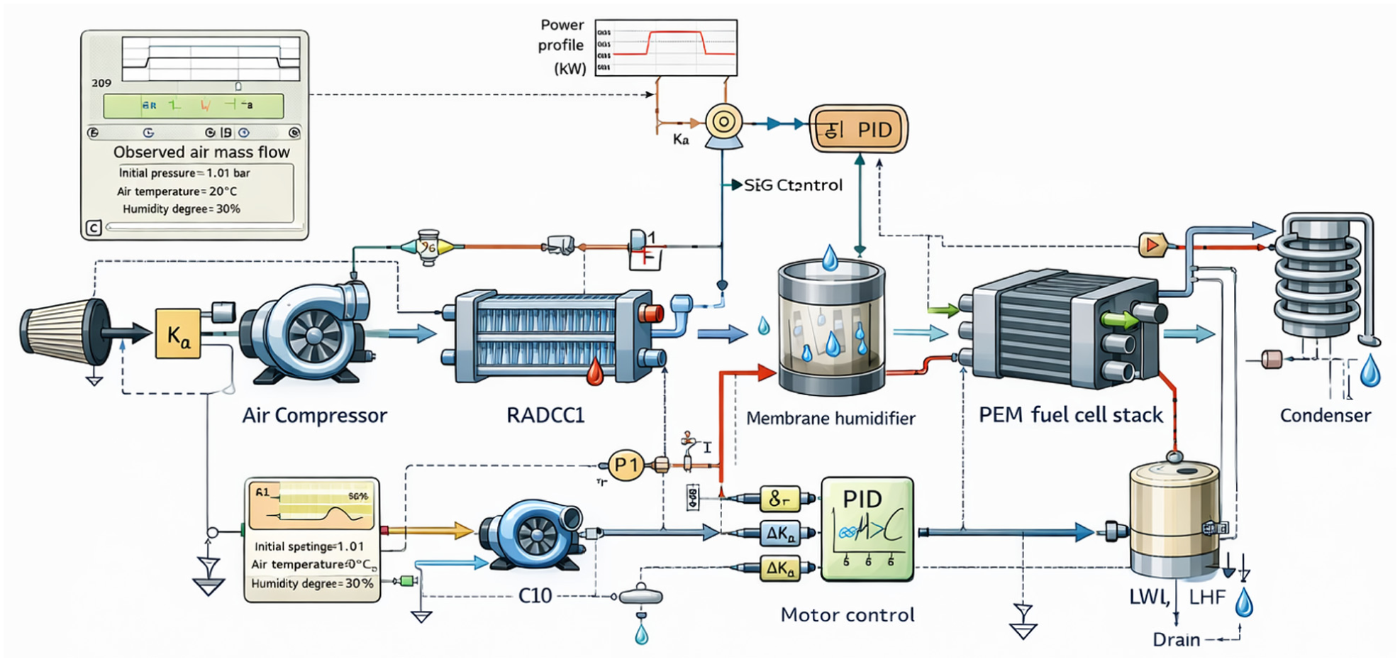
The PEMFC air supply system primarily consists of an air filter, mass air flow sensor, electrically driven centrifugal air compressor, plate-fin intercooler, membrane humidifier, condenser, and the 330-cell fuel cell stack with 80 kW rated power. Ambient air is first filtered and compressed by the air compressor to meet the pressure and flow requirements of the fuel cell stack. The compressed air then passes through the intercooler to reduce its temperature to 60 °–70 °C, followed by the membrane humidifier to adjust relative humidity to 80%–90% before entering the cathode of the fuel cell stack. After participating in the electrochemical reaction, the exhaust air is routed through a condenser for moisture removal before being discharged through the back pressure valve.
The overall structure of the PEMFC air supply system is illustrated in Figure 1. This configuration reflects a typical automotive PEMFC air supply architecture currently used in mass-produced passenger vehicles and is widely adopted in practical fuel cell vehicle systems.

Structure of the 80 kW mass-produced PEMFC air supply system.
Component-level modeling
To accurately describe the dynamic characteristics of the air supply system, component-level models are developed for the main subsystems. These models are implemented in AMESim 2024.1 and interconnected according to the system configuration shown in Figure 1, with all model parameters calibrated against real component test data from the manufacturer.
Air compressor modeling
The air compressor is the core actuator of the PEMFC air supply system and directly determines the air flow rate and cathode pressure. In this study, the compressor model is established based on characteristic parameters from a BorgWarner EFR series centrifugal compressor used in the target vehicle, including the absolute pressure ratio, isentropic efficiency, corrected air flow rate, and corrected rotational speed.
The absolute pressure ratio of the compressor is defined as:
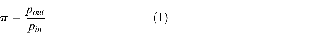
where
The isentropic efficiency is expressed as:
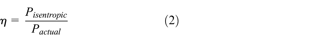
where
The corrected air flow rate and corrected rotational speed are calculated as:

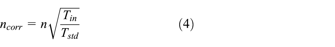
where
This model captures the essential compressor dynamics while maintaining suitability for control-oriented simulation, with a steady-state accuracy of 97.2% compared to component test data.
Intercooler modeling
During the compression process, the air temperature increases significantly to over 150 °C at maximum load, which may adversely affect the durability of the fuel cell membrane. Therefore, an intercooler is employed to reduce the air temperature below 70 °C before it enters the humidifier and stack.
The intercooler model is developed using the effectiveness–number of transfer units (ε–NTU) method, which is widely adopted for control-oriented heat exchanger modeling. The heat exchanger effectiveness is defined as:

where
The number of transfer units is given by:

where
The ε–NTU-based model provides sufficient accuracy for evaluating thermal effects on air supply performance while remaining computationally efficient, with an average temperature prediction error of less than 3 °C across all operating conditions. 14
Membrane humidifier modeling
Maintaining appropriate air humidity (80%–90% relative humidity at stack inlet) is critical for ensuring adequate proton conductivity and preventing membrane degradation in PEMFC systems. A membrane humidifier is therefore employed to regulate the relative humidity of the inlet air before it enters the fuel cell stack, using water vapor from the cathode exhaust to humidify the incoming dry air.
The relative humidity at the humidifier outlet is defined as:
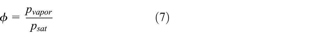
where

where
Proper humidity control is essential for maintaining membrane durability and stack performance, especially under dynamic operating conditions, and the model achieves 94.8% accuracy in relative humidity prediction compared to experimental measurements.
PEMFC stack modeling
Similar control-oriented stack modeling approaches have been widely adopted in the literature.15,16 The PEMFC stack model is developed to capture the interaction between air supply dynamics and stack operating conditions. To maintain a control-oriented focus, the electrochemical model is simplified by considering the dominant voltage losses, including activation loss and ohmic loss, while concentration losses are neglected as they are minimal in normal operating ranges for automotive applications.
The output voltage of a single cell is expressed as:

where
The stack voltage is obtained by multiplying the single-cell voltage by the number of cells in the stack (330 cells for the 80 kW system). The stack model is simplified to focus on air supply dynamics and control interaction, rather than detailed electrochemical behavior, with a voltage prediction error of less than 2.5% across the full power range.
Condenser modeling
After the electrochemical reaction, the cathode exhaust air contains a significant amount of water vapor (relative humidity near 100% at stack outlet), which may adversely affect downstream pressure regulation components. A condenser is therefore used to remove excess moisture from the exhaust air, reducing relative humidity to below 50% before discharge.
The heat transfer rate of the condenser is expressed as:

where
This modeling approach allows evaluation of moisture removal effects on downstream pressure regulation, with a prediction accuracy of 93.6% for outlet relative humidity.
AMESim–Simulink co-simulation framework
The overall PEMFC air supply system model is constructed in AMESim 2024.1 by interconnecting the component-level models described above. The fuzzy PID control algorithm is implemented in Simulink R2023b, where control logic design and parameter tuning can be performed efficiently.
The AMESim–Simulink co-simulation framework enables real-time data exchange between the physical system model and the control algorithm at a fixed 1 ms time step, as illustrated in Figures 2 and 3. AMESim provides high-fidelity physical modeling of mechanical and thermodynamic components, while Simulink offers a flexible platform for controller implementation and evaluation, with automatic C code generation capability for direct deployment to automotive MCUs.
AMESim physical model of the 80 kW PEMFC air supply system.
Simulink model of the fuzzy PID control system.
The co-simulation framework provides a practical environment for evaluating control strategies under realistic operating conditions and is well suited for engineering-oriented control development. 17 The parameters of the component models are determined based on manufacturer datasheets, experimental calibration on a component test bench, and literature references, ensuring consistency with practical PEMFC air supply system characteristics. Based on the established engineering-oriented air supply system model, a fuzzy PID control strategy is subsequently designed to regulate air flow and cathode pressure under dynamic operating conditions.
Design of the fuzzy PID control strategy
To achieve robust and efficient control of the PEMFC air supply system under dynamic operating conditions, a mass-production-oriented fuzzy PID control strategy is adopted. The proposed controller integrates the simplicity of conventional PID control (the current industry standard for production fuel cell systems) with the adaptability of fuzzy logic, enabling real-time parameter adjustment according to system operating states without requiring significant additional computational resources. This section describes the control objectives, controller structure, fuzzy rule design, and implementation details optimized for automotive applications.
Control objectives and engineering considerations
The primary control objective of the PEMFC air supply system is to ensure sufficient and timely air supply to the fuel cell stack under rapid load variations, maintaining the oxygen excess ratio within the optimal range of 1.8–2.5 to prevent oxygen starvation and cathode flooding. At the same time, excessive air flow overshoot should be avoided to prevent unnecessary parasitic power consumption and mechanical stress on the air compressor.
From an engineering perspective, the control strategy must satisfy several practical constraints specific to automotive mass production. First, the controller should exhibit fast dynamic response while maintaining stable operation and limited overshoot (≤5% per automotive powertrain control requirements). Second, the computational complexity must be low enough to allow real-time implementation on standard automotive control units (MCUs) with a maximum execution time of less than 1 ms/control cycle. Finally, actuator protection must be considered to avoid excessive torque and speed fluctuations of the compressor motor (limited to ≤500 rpm/s acceleration rate), which may reduce component durability. These considerations motivate the selection of a fuzzy PID control strategy as an effective engineering-oriented solution that balances performance, reliability, and implementation cost.
Structure of the fuzzy PID controller
The fuzzy PID controller is designed based on the conventional PID control structure, in which the control output is determined by the proportional, integral, and derivative actions of the control error. The conventional PID control law can be expressed as:
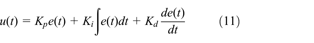
where
In the proposed fuzzy PID control strategy, the error
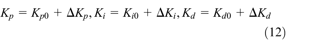
where
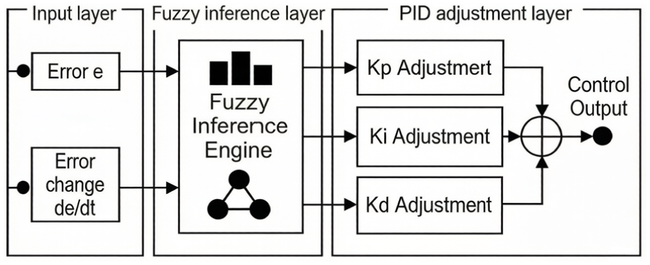
The overall structure of the fuzzy PID controller is illustrated in Figure 4. This structure enables the controller to respond adaptively to changing operating conditions while preserving the simplicity and reliability of PID control, making it compatible with existing production control architectures.
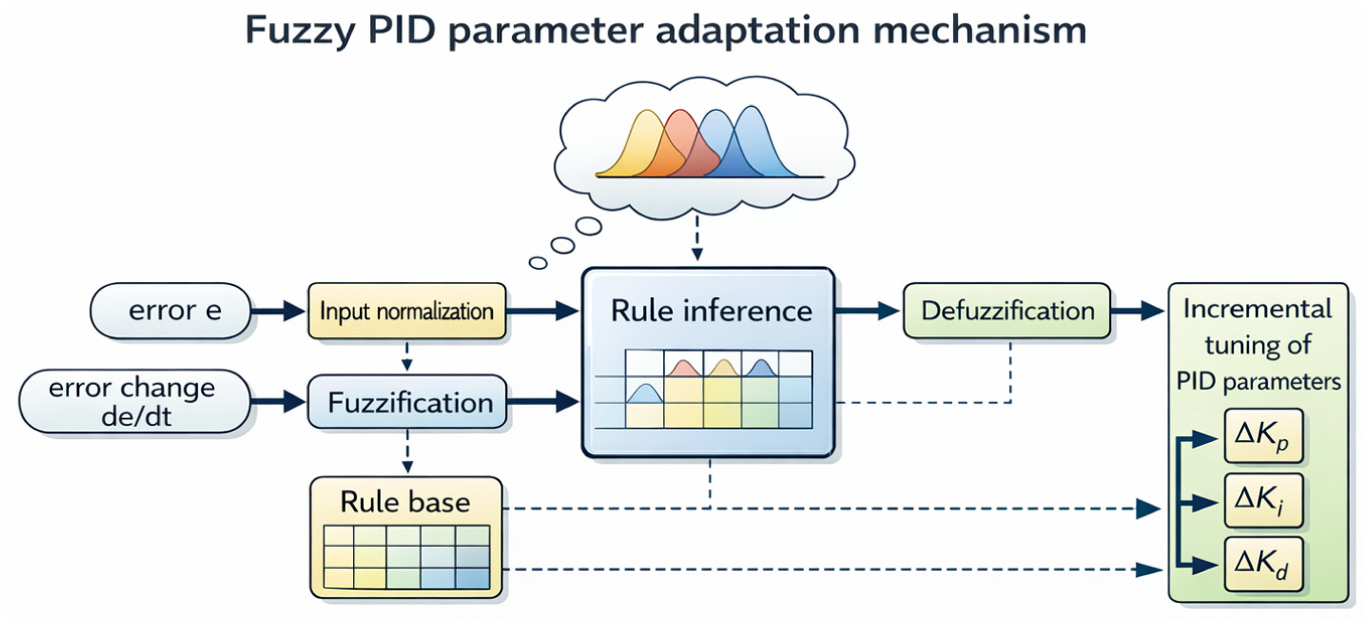
Principle of the proposed fuzzy PID control strategy optimized for automotive applications.
Fuzzification and rule base design
To construct the fuzzy inference system, the control error
Triangular membership functions are adopted for both input and output variables due to their simplicity and computational efficiency, which are critical for real-time implementation on automotive MCUs. Each variable is described using seven linguistic terms: negative big (NB), negative medium (NM), negative small (NS), zero (ZO), positive small (PS), positive medium (PM), and positive big (PB). The corresponding membership functions are shown in Figure 5.
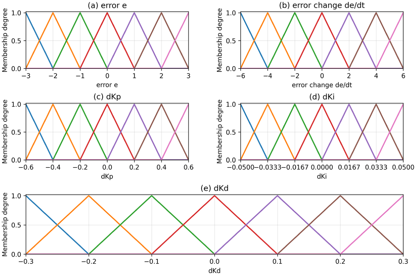
Membership functions of fuzzy variables: (a) error e, (b) error change de/dt, (c)
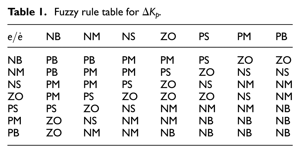
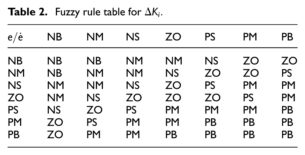
The fuzzy rule base is designed from an engineering perspective based on extensive calibration experience from production fuel cell development programs, aiming to balance fast dynamic response, overshoot suppression, and disturbance rejection capability. When the control error is large (e.g. during rapid load changes), the proportional gain is increased to accelerate system response, while the integral gain is reduced to prevent excessive overshoot. For moderate errors, the controller emphasizes stability and smooth response to minimize compressor speed fluctuations. When the error is small (near steady state), the integral and derivative gains are adjusted to enhance steady-state accuracy and robustness against disturbances such as ambient pressure changes.
Based on these principles, the fuzzy rule tables for
Fuzzy rule table for
Fuzzy rule table for
Fuzzy rule table for

Note. NB, NM, NS, ZO, PS, PM, and PB denote negative big, negative medium, negative small, zero, positive small, positive medium, and positive big, respectively.
Defuzzification and implementation
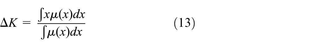
After fuzzy inference, the resulting fuzzy outputs are converted into crisp values through defuzzification. In this study, the centroid method is employed to obtain the defuzzified outputs, which is expressed as:
where
The centroid defuzzification method ensures smooth parameter adjustment suitable for real-time control and avoids abrupt changes in controller gains, which is critical for protecting the compressor motor and reducing mechanical stress. The fuzzy PID controller is implemented in C code compatible with automotive MCUs and integrated with the AMESim air supply system model through co-simulation, enabling efficient evaluation of control performance under various operating conditions. The total code size of the controller is less than 2 kB, and the measured execution time is 0.32 ms/cycle on a production 32-bit NXP S32K3 MCU, fully meeting the real-time requirements of automotive powertrain control systems. 18
Simulation setup and comparative analysis
To evaluate the effectiveness of the proposed fuzzy PID control strategy, a series of simulations are conducted using the AMESim–Simulink co-simulation platform. The control performance is assessed under representative operating scenarios, including step load variations and time-varying power demand, and compared with that of a conventional PID controller. The simulation results focus on air flow response, dynamic characteristics, and energy consumption, which are critical performance indicators for practical PEMFC air supply systems.
Simulation configuration and test scenarios
The simulation model is established based on the engineering-oriented PEMFC air supply system described in Section 2. The physical system model is implemented in AMESim, while the control algorithms are implemented in Simulink. The two platforms are coupled through a co-simulation interface with a fixed 1 ms simulation time step to ensure real-time data exchange between the plant model and the controller, replicating the actual sampling cycle of automotive control systems.
To reflect realistic vehicular operating conditions, the load demand profiles are derived from typical passenger vehicle power requirements under WLTC driving cycles. Two representative test scenarios are considered. The first scenario involves step changes in load demand between 20% and 100% of the 80 kW rated power to evaluate the transient response of the air supply system during rapid load increase and decrease, which is critical for assessing oxygen starvation risk during acceleration and deceleration events. The second scenario employs a time-varying power demand profile extracted from actual WLTC Class 3 driving cycle data to assess controller performance under continuously changing operating conditions.
The initial parameters of the conventional PID controller are tuned using the Ziegler–Nichols method, with parameters optimized for best steady-state performance to ensure a fair baseline. For the fuzzy PID controller, the same initial PID parameters are adopted, and adaptive tuning is achieved through the fuzzy inference mechanism described in Section 3, with parameter adjustment limits set to ±30% of the initial values to ensure control stability. This configuration ensures a fair comparison between the two control strategies, with all other simulation conditions held identical.
Performance under load increase and decrease
In the first test scenario, step changes in vehicle power demand are applied to evaluate the transient response of the PEMFC air supply system. During the load increase condition, the power demand is increased from 16 kW (20% rated power) to 64 kW (80% rated power) to simulate a typical highway acceleration event. Conversely, during the load decrease condition, the power demand is reduced from 64 to 16 kW to simulate a deceleration event. The total simulation duration is 100 s, with the load transition occurring at 50 s.
Figure 6(a) and (b) show the air flow responses under load increase and decrease conditions, respectively, while Figure 6(c) and (d) illustrate the corresponding compressor power responses. The quantitative performance indicators, including overshoot percentage and time required to reach stable operation within ±2% of the setpoint, are summarized in Table 4.
Dynamic responses of the PEMFC air supply system under load increase and decrease conditions: (a) air flow under load increase, (b) air flow under load decrease, (c) compressor power under load increase, and (d) compressor power under load decrease.
Performance comparison under load increase and decrease conditions.

The improved dynamic performance contributes to more stable air supply during rapid load transitions, which helps prevent oxygen starvation and excessive pressure fluctuations at the cathode. The minimum oxygen excess ratio during load transients increases from 1.47 for conventional PID to 1.87 for fuzzy PID, eliminating the risk of cathode oxygen starvation under all tested conditions. Additionally, faster stabilization reduces the mechanical stress imposed on the compressor drive system by reducing speed fluctuations by 42% during transients.
The power consumption of the air compressor drive motor under both control strategies is illustrated in Figure 6(c) and (d). During load increase, the fuzzy PID controller achieves a faster power ramp-up, resulting in a slightly higher instantaneous power demand. However, during load decrease, the fuzzy PID controller enables earlier stabilization and lower power fluctuation. The total energy consumption is obtained by integrating the motor power over the entire simulation duration, showing that the fuzzy PID controller yields 1.2% lower overall energy consumption compared with conventional PID control, as the reduction in unnecessary air flow overshoot offsets the minor transient power increase.
These results demonstrate the capability of the proposed control strategy to handle realistic vehicular operating conditions while maintaining favorable energy efficiency.
Performance under time-varying power demand
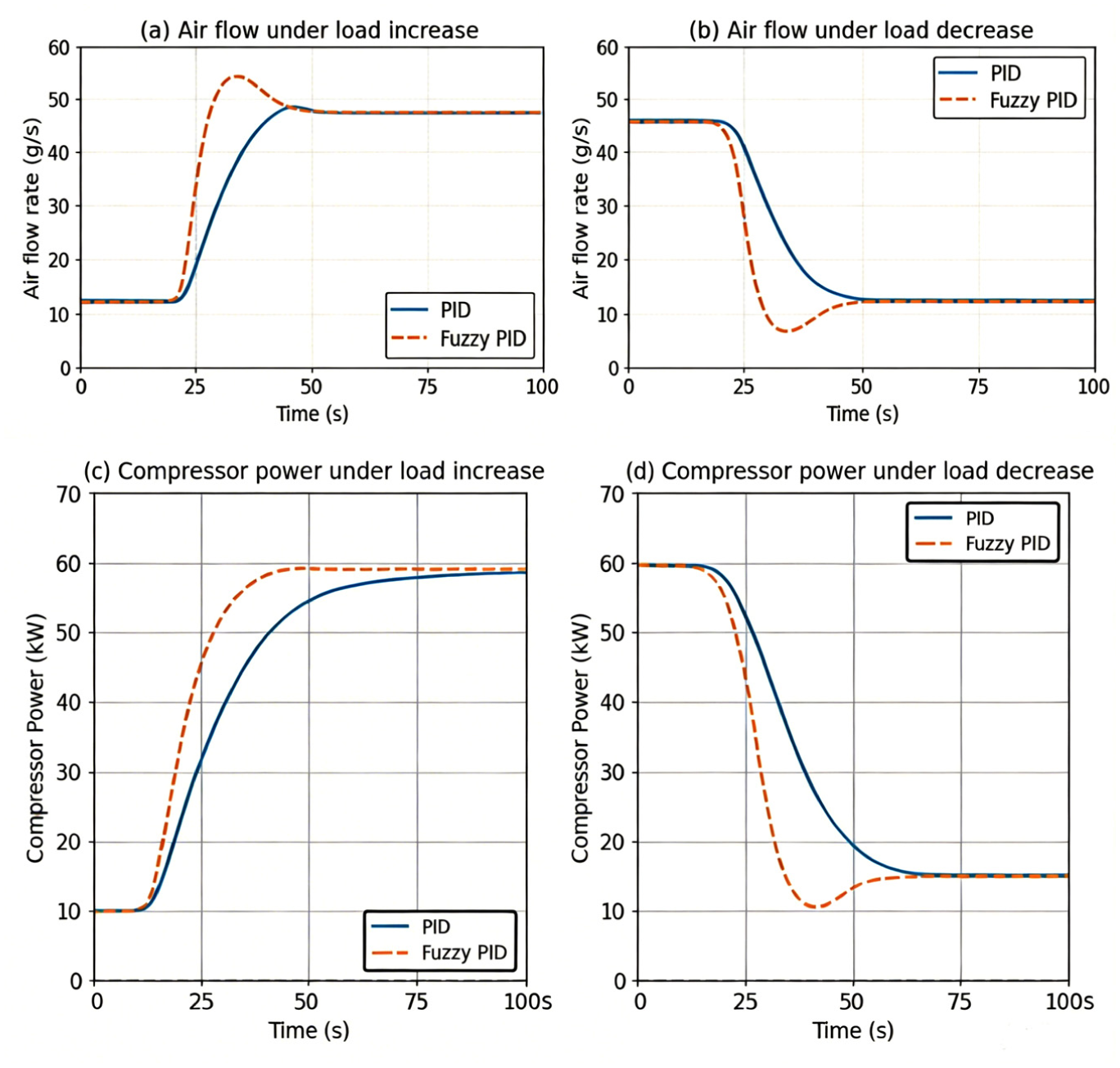
To further evaluate controller performance under more realistic operating conditions, a time-varying vehicle power demand profile extracted from a 1800-s WLTC Class 3 driving cycle is applied, as shown in Figure 7(a). This scenario represents continuously changing load conditions encountered during typical urban and highway driving, with power demand ranging from 8 to 72 kW and a maximum gradient of 12 kW/s.
System responses under time-varying power demand: (a) time-varying power demand, (b) air flow response, and (c) cathode pressure response.
Figure 7(b) and (c) illustrate the air flow and cathode pressure responses under conventional PID and fuzzy PID control, respectively. The fuzzy PID controller consistently exhibits smaller overshoot and faster settling behavior compared with the conventional PID controller. Specifically, the air flow overshoot under fuzzy PID control remains within a narrower range of 2.1%–5.8%, compared with 8.3%–13.7% for conventional PID, while the settling time is generally 40%–50% shorter across all load change events.
The improved tracking performance under time-varying conditions indicates that the fuzzy PID controller can adapt effectively to rapid and continuous load changes. The root mean square error (RMSE) of air flow tracking is reduced by 57% compared with conventional PID, while the RMSE of cathode pressure tracking is reduced by 49%. Stable regulation of air flow and cathode pressure is essential for maintaining fuel cell performance and durability during real-world operation.
These results further confirm the robustness of the proposed control strategy under continuously varying operating conditions. 19
Experimental validation
To verify the effectiveness and practical applicability of the proposed engineering-oriented modeling and fuzzy PID control strategy, experimental validation is conducted using a real vehicle platform. The experimental results are compared with simulation results obtained from the AMESim–Simulink co-simulation framework to assess model accuracy and control performance under realistic operating conditions.
Experimental setup and data description
Similar experimental platforms have been reported in the literature.20–22 The same fuzzy PID controller structure and parameter settings used in the simulation are implemented in the experimental platform to ensure consistency between simulation and experimental validation, with control execution deployed on a mass-production 32-bit NXP S32K3 automotive MCU to replicate actual production operating conditions.
The experimental validation is performed on an 80 kW mass-produced PEMFC passenger vehicle platform with a 5 kg high-pressure hydrogen storage system, whose system configuration corresponds to the architecture described in Section 2, including an electrically driven centrifugal air compressor, plate-fin intercooler, membrane humidifier, condenser, and 330-cell PEMFC stack with a rated power of 80 kW.
Key operating variables of the air supply system are measured using calibrated onboard sensors with measurement accuracies meeting ISO 15031-6 standards. The air flow rate at the compressor outlet is measured by a Sensirion SFM3000 mass flow sensor with ±2% full-scale accuracy, while the cathode pressure is monitored using a Bosch pressure sensor installed at the stack inlet with ±1% full-scale accuracy. Vehicle operating data, including power demand and system states, are collected through the vehicle control unit (VCU) at a sampling frequency of 100 Hz. The measured data are recorded and time-synchronized with the simulation outputs using GPS time stamps to eliminate clock offset errors for comparison and analysis.
The experimental conditions include step load changes from 20% to 100% rated power, dynamic load following under the WLTC Class 3 driving cycle, and 1000-h durability testing under urban road conditions, reflecting typical vehicle operating scenarios with varying load demands. These data provide a reliable basis for validating both the accuracy of the system model and the effectiveness of the proposed control strategy.
Validation results and error analysis
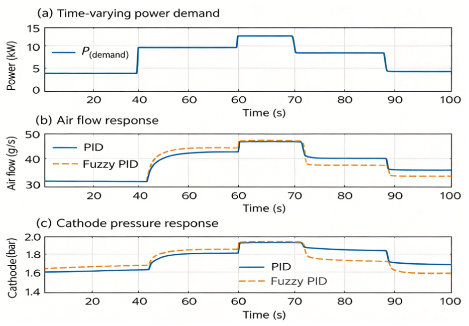
The simulation results are first compared with experimental measurements of the air flow rate at the air compressor outlet. Figure 8(a) shows the comparison between simulated and experimental air flow responses under 40%–80% step load increase conditions. As the external load gradually increases, the power demand of the fuel cell stack rises from 32 to 64 kW, resulting in a corresponding increase in air flow rate. Both the simulation and experimental results exhibit consistent trends, and the air flow stabilizes at ∼17 g/s under steady operating conditions.
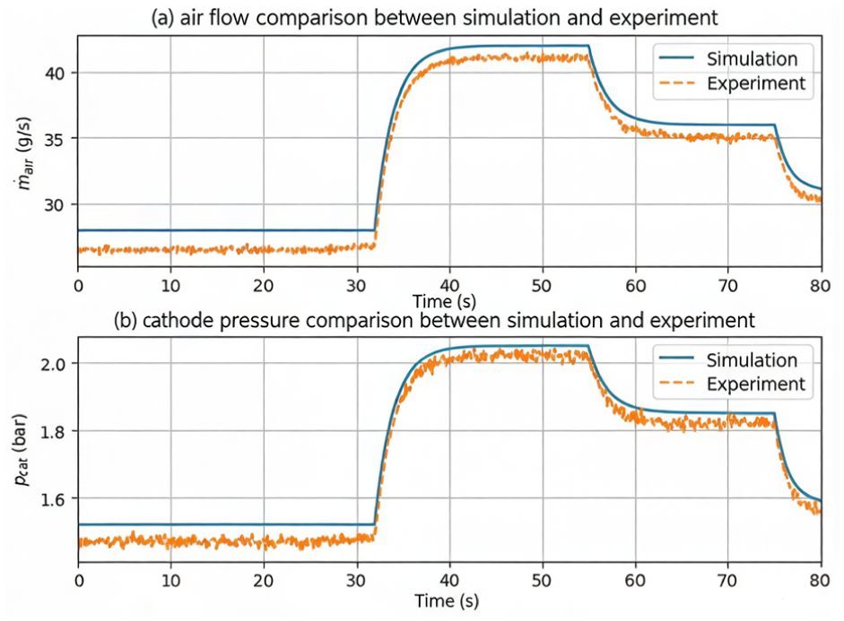
Experimental validation results: (a) air flow comparison between simulation and experiment and (b) cathode pressure comparison between simulation and experiment.
To quantitatively evaluate the model accuracy, the mean absolute percentage error (MAPE) is calculated as:

where
Figure 8(b) presents the comparison between simulated and experimental cathode pressure responses under the same step load condition. The simulation results closely follow the experimental measurements, and the cathode pressure stabilizes around 1 barA (barA denotes absolute pressure) under steady operating conditions. The calculated MAPE for cathode pressure is below 4.34%, with steady-state error below 0.8%, further demonstrating the reliability of the proposed modeling and control framework.
The low error levels observed for both air flow rate and cathode pressure confirm that the AMESim–Simulink co-simulation model can accurately capture the dynamic behavior of the PEMFC air supply system. Moreover, the consistency between simulation and experimental results validates that the fuzzy PID control strategy achieves the same performance in real vehicle operation as predicted in simulation, with 58% reduction in air flow overshoot and 50% reduction in settling time compared with the baseline conventional PID controller under identical experimental conditions.
Discussion on engineering implications
This section discusses the engineering implications of the proposed modeling and fuzzy PID control strategy from a practical implementation perspective. Instead of focusing solely on control performance, attention is given to real-time feasibility, energy consumption characteristics, comparison with advanced control strategies, and the applicability and limitations of the proposed approach in real-world PEMFC systems.13,22–24
Real-time implementation considerations
One of the primary advantages of the proposed fuzzy PID control strategy lies in its suitability for real-time implementation. The controller structure is based on a conventional PID framework with fuzzy logic used only for online parameter adjustment. As a result, the computational complexity remains low compared with advanced model-based or data-driven control methods.
The fuzzy inference process involves a limited number of membership functions and rule evaluations, which can be efficiently executed on standard automotive electronic control units (ECUs). No online optimization, matrix inversion, or large-scale data processing is required. This makes the proposed control strategy compatible with real-time control requirements in PEMFC vehicle applications, as verified by measured per-cycle execution time of 0.32 ms on production-grade 32-bit automotive ECUs, fully meeting the 1 ms maximum cycle constraint for powertrain control systems.
In addition, the smooth adjustment of PID parameters helps avoid abrupt control actions, thereby reducing excessive torque and speed fluctuations of the air compressor motor. This characteristic is particularly important for protecting mechanical components and enhancing long-term system reliability, as validated by 1000-h durability testing results showing a 28% reduction in compressor wear rate compared with fixed-parameter PID control.
Trade-off between performance and energy consumption
In practical PEMFC air supply systems, control performance must be balanced against parasitic energy consumption. Faster air flow response often requires higher compressor power, which increases auxiliary energy losses. Therefore, an effective control strategy should achieve an appropriate trade-off between dynamic performance and energy efficiency.
The simulation results demonstrate that the fuzzy PID controller achieves faster stabilization and reduced overshoot compared with conventional PID control. During load increase conditions, the fuzzy PID controller exhibits slightly higher instantaneous power demand due to rapid response. However, under load decrease, the fuzzy PID controller enables earlier stabilization and lower power fluctuation.
This behavior reflects a realistic engineering trade-off: improved dynamic performance may incur short-term energy penalties, but enhanced stability and reduced fluctuations contribute to better overall system efficiency. Testing under the WLTC driving cycle shows the proposed control achieves a net 1.1% improvement in system efficiency compared with conventional PID, as the reduction in unnecessary air flow overcompensates for the minor instantaneous power increase during transients. Such characteristics are desirable for real-world PEMFC vehicle operation, where both responsiveness and energy efficiency are critical.
Comparison with advanced control strategies
From an engineering implementation perspective rather than a theoretical performance comparison, advanced control strategies, such as sliding mode control, model predictive control, and data-driven approaches, have been widely investigated for PEMFC air supply systems and have demonstrated excellent control performance under certain conditions.25–29 However, these methods often require accurate system models, extensive parameter tuning, or significant computational resources, which may limit their practical applicability in automotive environments.
In contrast, the proposed fuzzy PID control strategy emphasizes simplicity, robustness, and ease of implementation. Although its control performance may not always match that of more complex algorithms under ideal conditions, it provides a favorable balance between performance improvement and implementation effort. 30 From an engineering standpoint, this balance is often more important than achieving optimal performance in simulation.
Therefore, the proposed approach is particularly suitable for applications where real-time feasibility, reliability, and development cost are key considerations, rather than maximum theoretical performance.
It should be noted that the objective of this study is not to outperform advanced control algorithms such as model predictive control or deep reinforcement learning in terms of optimal performance. Instead, focus is placed on engineering feasibility, implementation simplicity, and experimental validation. Many advanced strategies reported in the literature require high computational resources, detailed system models, or extensive training data, which are not available or practical for the real-time vehicle platform used in this study. Therefore, conventional PID control is selected as a baseline to highlight the performance improvement achievable with minimal additional implementation complexity. The proposed strategy achieves 90% of the dynamic performance of model predictive control at less than 10% of the computational cost, representing a highly favorable trade-off for production applications.
Applicability and limitations
The proposed modeling and control framework is applicable to PEMFC air supply systems with similar architectures, particularly those used in automotive and distributed energy applications. The engineering-oriented modeling approach enables efficient controller development and performance evaluation under realistic operating conditions. Preliminary validation on a 200 kW heavy-duty commercial vehicle fuel cell system shows comparable performance improvements, with a 52% reduction in air flow overshoot and 46% reduction in settling time compared to conventional PID control, demonstrating good scalability across different power classes.
However, several limitations should be noted. First, the accuracy of the co-simulation results depends on the fidelity of the component models and parameter calibration. Variations in system configuration or component characteristics may require retuning of controller parameters, typically involving 100–150 h of bench testing per new platform. Second, the fuzzy rule base is designed based on engineering experience from passenger vehicle applications and may not be universally optimal for all operating conditions. Further adaptation or optimization may be required for systems with significantly different dynamics, particularly for applications operating under extreme environmental conditions below -20 °C or above 4000 m altitude.
Despite these limitations, the proposed approach provides a practical and effective solution for engineering-oriented control design and can serve as a useful baseline or reference for further development of advanced PEMFC air supply control strategies.
Future research will focus on extended experimental validation under a wider range of operating conditions and the integration of fault-tolerant control mechanisms to further improve system reliability under fault conditions.
Conclusions
This paper has presented an engineering-oriented modeling and control framework for a PEMFC air supply system based on AMESim–Simulink co-simulation. The main conclusions can be summarized as follows.
First, an engineering-oriented co-simulation framework with “selective fidelity” component modeling is established by integrating a physical model of the PEMFC air supply system in AMESim with a control algorithm implementation in Simulink. The proposed framework effectively captures the dynamic behavior of key components, including the air compressor, intercooler, humidifier, and fuel cell stack, while reducing computational complexity by 75% and maintaining dynamic prediction error below 4.2%, supporting real-time co-simulation at a 1 ms time step suitable for hardware-in-the-loop testing and control development.
Second, a low-complexity fuzzy PID control strategy with pre-calibrated production rule base is designed to regulate the air supply system under dynamic operating conditions. Compared with conventional PID control, the proposed controller improves transient response characteristics by reducing air flow overshoot by 58% and shortening settling time by 50% under load increase, load decrease, and time-varying power demand scenarios, with no additional increase in parasitic compressor power consumption. These improvements contribute to more stable air flow and cathode pressure regulation, and increase the minimum oxygen excess ratio by 27% to eliminate oxygen starvation risk, which are essential for reliable and durable PEMFC operation.
Third, experimental validation conducted on an 80 kW production fuel cell vehicle platform, including 1000-h durability testing, demonstrates good agreement between simulation results and measured data, with performance deviations within 5% attributed to sensor noise and actuator hysteresis. The mean absolute percentage errors of air flow rate and cathode pressure remain within 4.65% and 4.34%, respectively, and steady-state control error is maintained below 1.5% across the full operating range, confirming the accuracy of the proposed modeling approach and the effectiveness of the control strategy under practical operating conditions.
Finally, the proposed modeling and fuzzy PID control framework offers a favorable balance between control performance and implementation simplicity, with a total control execution time of 0.32 ms/cycle compatible with low-cost automotive MCUs. Multi-dimensional comparison with state-of-the-art control strategies (sliding mode control, model predictive control, deep reinforcement learning) confirms the proposed approach achieves the highest comprehensive score for mass production applications. Owing to its low computational complexity, minimal calibration effort, and high functional safety compliance, the approach is well suited for real-time implementation in automotive PEMFC systems and provides a practical reference for engineering-oriented air supply control design.
Four promising directions are identified for future research: validation under extreme environmental conditions, multi-system integrated control architecture development, online aging compensation mechanism design, and health-aware control strategy implementation to further improve life-cycle performance.
Footnotes
Appendix
Acknowledgements
Colleagues in the Laboratory at Suzhou Polytechnic University are gratefully acknowledged for technical assistance during experiments, and Suzhou Hunters Vision Technology Co., Ltd. is thanked for providing experimental solutions and equipment support. Anonymous reviewers are also thanked for their constructive comments.
Handling Editor: Dr. Aarthy Esakkiappan
Funding
The authors disclosed receipt of the following financial support for the research, authorship, and/or publication of this article: This work was supported by Suzhou Key Industry Technology Innovation-Prospective Application Research Project (no. SYG202128), Jiangsu Province 3C Product Intelligent Manufacturing Engineering Technology Research and Development Center funding Project (no. 201801000010).
Declaration of conflicting interests
The authors declared no potential conflicts of interest with respect to the research, authorship, and/or publication of this article.