
Abstract
Cutterhead is the core component of the tunnel boring machine (TBM). In slurry TBM engineering, conventional and atmospheric cutterheads are usually associated with different cutterhead structure, cutter change mode and auxiliary system configurations, which may lead to different responses under complex geological conditions. To explore the tunneling performance and differences, this study presents a comparative field case analysis of two slurry TBM system configurations featuring conventional and atmospheric cutterheads in the parallel tunnels of the Haizhuwan Tunnel Project. First, the tunneling performance under four representative geological conditions was analyzed based on tunneling data, equipment modifications, and cutter failure characteristics. Subsequently, the Kruskal-Wallis test was used to compare the tunneling differences between the two machine configurations, with tunneling time per ring and construction time per ring taken as the main evaluation indicators. The results show that, under the investigated project conditions, in challenging environments, such as soft soil strata with poor formation stability, the atmospheric cutterhead configured system demonstrates better tunneling performance. In contrast, in hard rock strata, particularly under high rock hardness conditions, conventional cutterhead configured system exhibits superior tunneling performance. These findings provide practical engineering reference for slurry TBM equipment configuration and construction organization under similar geological conditions.
Keywords
Introduction
Slurry TBMs have been widely used in river and sea crossing tunnels due to their advantages of minimal disturbance to strata and high construction efficiency, particularly in complex geological environments characterized by large diameters, deep burial depths, high pressures, and abundant groundwater.1–4 Based on different cutter-change mechanisms, the slurry TBMs are mainly categorized into two types: conventional cutterhead (CCH) and atmospheric cutterhead (ACH). Both types are widely used in practical engineering projects. For instance, CCH has been applied in the Hangzhou Tianmushan Road to Huancheng North Road upgrade project, Zhuhai Xingye Expressway, and Zhuhai Hengqin Mangzhou Tunnel.5–7 ACH has been utilized in the Nanjing Yangtze River Tunnel, Sutong GIL Yangtze River, Wuhu River-Crossing Tunnel, and Chunfeng Tunnel.8–11 However, due to significant differences in cutterhead structure, cutter configuration, and cutter-change modes, the specific tunneling performance and geological adaptability of these two types of cutterheads remain unclear. In light of the complex and variable geological conditions encountered in tunnel engineering, there is still a lack of a solid theoretical foundation and sufficient construction data to guide the scientific selection of slurry TBM cutterhead-system configurations.
In the construction of shield tunnels, the diversity of geological conditions presents challenges to the adaptability of the shield machine, such as mud cakes on the cutterhead,12–14 abnormal wear of the cutters,15,16 muck retention,17,18 and slurry pump blockage. The reasonable selection of shield machines and their configurations is an effective strategy to shorten construction time and reduce costs. 19 To explore the adaptability of different types and structures of cutterheads to geological conditions, several studies have compared the tunneling performance of different cutterheads in the context of practical engineering projects. For example, by comparing and analyzing the performance of three different cutterhead structures in the water-rich sandy and cobble strata of Chengdu Metro Line 6, Wan and Jin 20 identified the cutterhead opening ratio, maximum opening size, and opening position as key factors affecting the geological adaptability of the shield machine. Shenzhen Metro Line 12 was taken as a case study, Wu et al. 21 analyzed the tunneling performance differences between an EPB-TBM dual-mode shield machine and a composite EPB shield machine. They found that for tunnels with soft soil and hard rock strata, the dual-mode shield performed better, while the composite EPB was more suitable for tunnels with short hard rock sections. Cao et al. 22 analyzed the clogging problem of two different cutterhead types in soft rock strata, where Nanchang Metro Line 1 was taken as an example. They pointed out that clay mineral content is a key factor causing cutterhead clogging and proposed suggestions for improving cutterhead structure and cutter configuration. In conclusion, the above studies primarily compare the tunneling performance of different cutterheads from a data analysis perspective and have yet to establish a systematic evaluation framework for in-depth investigation of their performance differences. Moreover, due to the diversity of strata, specially customized cutterheads are often used in actual shield tunnel construction. As a result, very few engineering cases are available for comparing the tunneling performance of different cutterheads under similar geological conditions. In practical slurry TBM engineering, differences in cutterhead type are often coupled with differences in cutter arrangement, opening ratio, and auxiliary system configuration. Therefore, strict single-factor comparisons are difficult to achieve in field projects.
Currently, there is still limited field-based evidence on the comparative tunneling performance of slurry TBM system configurations featuring CCH and ACH under broadly similar geological conditions. Furthermore, a comprehensive and quantitative analysis method for evaluating the tunneling performance of different cutterheads is lacking, which makes it challenging for construction personnel to make optimal decisions during the shield machine and cutterhead selection process.
Using the parallel tunnels of the Haizhuwan Tunnel Project as a case study, this paper presents a field-based comparative analysis of two slurry TBM configurations equipped with conventional and atmospheric cutterheads, respectively. First, the structural characteristics, supporting system configurations, and operational data of the two machines are introduced, and a comparable dataset is established through data extraction and preprocessing. Then, the tunneling responses of the two configurations under different strata are analyzed from the perspectives of operational parameters, tunneling time, and cutter-related observations. Considering the coupled differences in cutterhead layout, cutter arrangement, replacement mode, and auxiliary system configuration, the study focuses on the overall field performance of the two machine schemes under broadly comparable geological conditions. The findings are expected to provide project-specific engineering reference for slurry TBM equipment configuration and construction organization in similar projects.
Brief description of the project
Project overview
The Haizhuwan Tunnel Project spans Haizhu District and Panyu District of Guangzhou City. The total length of the line is 4.3 km, with the shield section measuring 2077 m and a maximum burial depth of 51 m. The tunnel passes through the Lijiao Waterway, Luoxi Island, and the Sanzhixiang Waterway of the Pearl River, featuring a double-tube tunnel, as shown in Figure 1. The shield section consists of two tunnels on the east and west lines, excavated by two slurry TBMs, with an excavation diameter of 15.07 m.
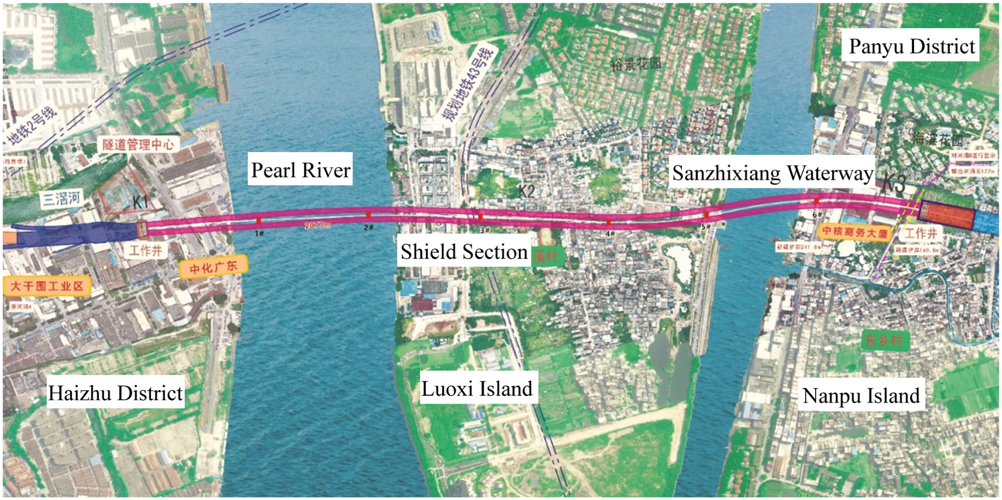
Layout of the Haizhuwan tunnel.
Geological features of the intervals
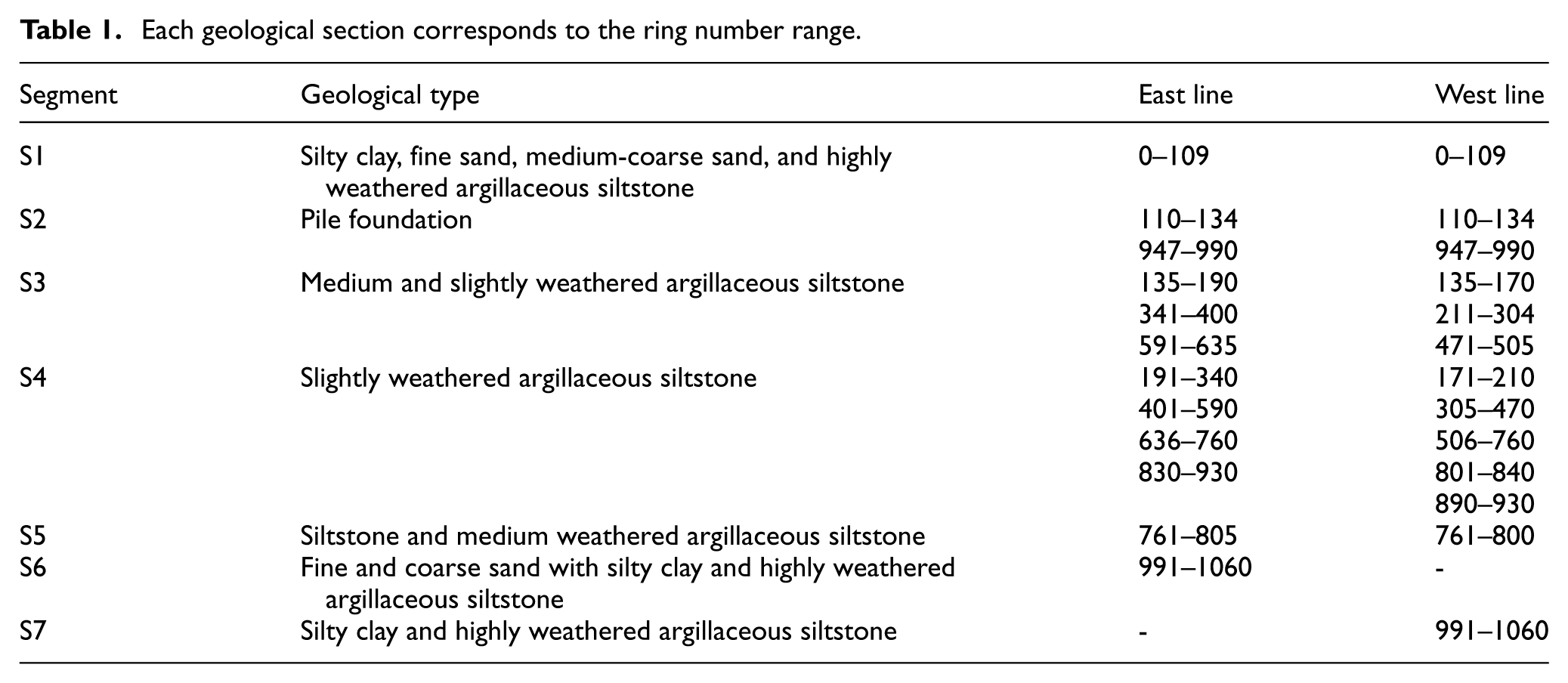
The geological profile of the tunnel is shown in Figure 2. Although the two tunnels are parallel and closely spaced, yielding broadly comparable stratigraphic frameworks overall, local differences in stratum thickness and ring-range distribution persist between the east and west lines. The strata encountered during excavation are complex, consisting of upper soft and lower hard composite strata, with pile foundation strata on both sides and hard rock strata in the center. The upper soft and lower hard strata primarily include silty clay, fine sand, fine and coarse sand, and highly weathered argillaceous siltstone, among others. These geological conditions are poor and unfavorable for the stability of the tunneling face. The hard rock strata are mainly composed of argillaceous siltstone, with the degree of weathering categorized into four types: complete weathering, strong weathering, moderate weathering, and slight weathering. The average rock strength is 20 MPa, with a maximum of 50 MPa. Based on the different strata, the geological profile is divided into seven sections, labeled S1–S7. The detailed geological information and corresponding ring number ranges are presented in Table 1. The comparative analyses in this study were mainly conducted by corresponding stratum intervals.
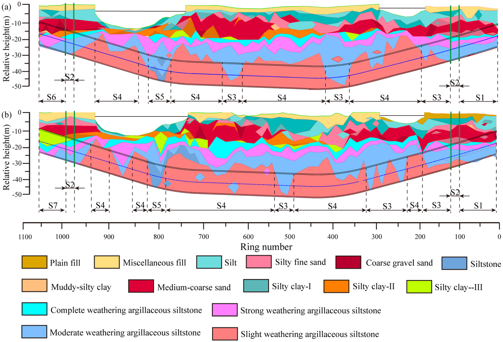
Geological profile of the Haizhuwan tunnel: (a) east line and (b) west line.
Each geological section corresponds to the ring number range.
Specifications of conventional and atmospheric cutterhead
The excavation diameter of the Haizhuwan Tunnel Project is large, and the geological conditions are complex, with both soft soil and hard rock strata, as well as the tunnel passing through the Pearl River and other bodies of water. Therefore, when selecting the shield machine, it is necessary to control ground subsidence in the soft soil layers to ensure construction safety, while also facilitating rapid excavation through the hard rock strata to improve tunneling efficiency. Slurry TBMs are typically chosen for the excavation of underwater tunnels. To conduct a comprehensive comparison and assessment of cutterhead performance, tunneling proceeded with CCH and ACH on the east and west lines, respectively. The structures of the two types of cutterheads are shown in Figure 3. The CCH has a spoke-plate structure, consisting of eight main spokes and auxiliary spokes. Disk cutters are mounted on the main spokes, while welded scraper cutters are installed on the auxiliary spokes. The ACH has a panel-type structure, composed of six radial arms, with replaceable disk cutters at the center of the arms and replaceable scraper and welded scrapers on either side of the radial arms. Compared to the ACH, the CCH has more cutters, resulting in better rock-breaking capability. Additionally, the CCH has a larger cutterhead opening ratio and thinner cutterhead, which facilitates mud discharge. However, for cutter inspection and replacement, the ACH can operate in atmospheric conditions in the radial arms, while the CCH must withstand the water and soil pressure within the excavation chamber. Therefore, the efficiency and safety of cutter replacement are higher for the ACH.
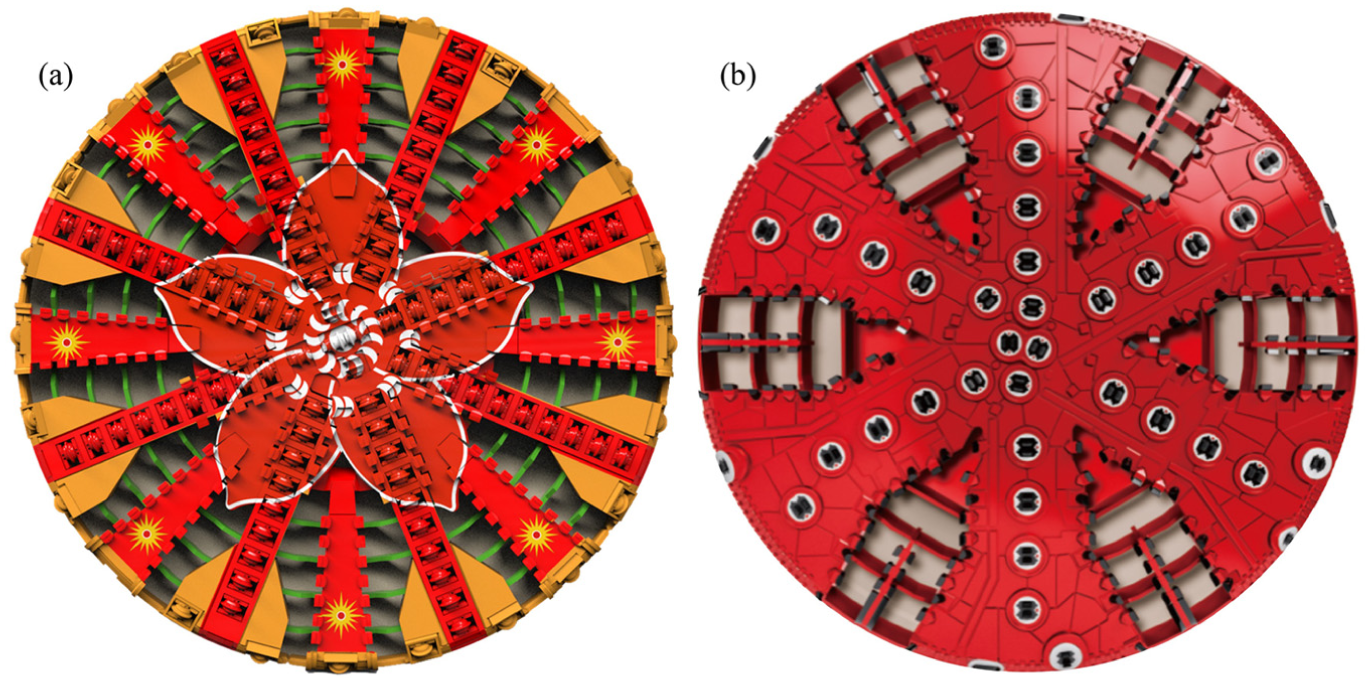
Structure diagram of cutterhead: (a) CCH and (b) ACH.
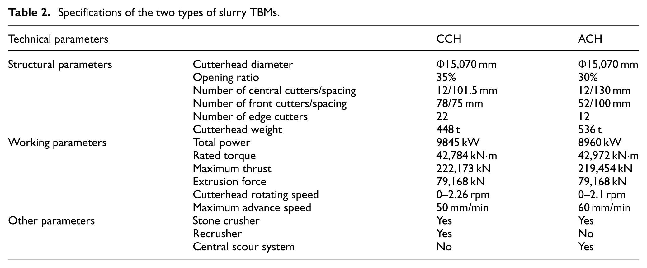
The specifications of the two types of slurry TBMs are shown in Table 2. The excavation diameters of the two cutterheads are identical, and their rated power, torque, thrust, and mud circulation capacity are nearly the same. However, due to differences in the structure of the cutterhead and tool holder, the two cutterheads exhibit significant variations in opening ratio, cutter spacing, and number of cutters. The cutter used in two cutterhead are shown in Figure 4.
Specifications of the two types of slurry TBMs.

Structure diagram of cutters: (a) single cutter on CCH and (b) double-edged cutter on ACH.
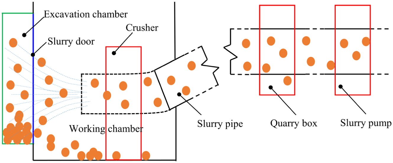
To prevent clogging of the slurry pump caused by oversized rock chips, a stone crusher was installed behind the cutterhead. Additionally, to better crush the rock chips and reduce wear on the slurry pipeline, the CCH includes a recrusher in front of the slurry discharge pump. To address the issue of the small central opening in the ACH and reduce the risk of clogging in the central area and mud cake formation on the cutterhead panel, an enhanced central scour system was specifically designed. This system increases the number of scour holes and pipelines on the cutterhead’s front panel. These measures collectively ensure the smooth progress of tunneling. The auxiliary system differences were considered part of the machine configuration background in the present field comparison and are discussed as potential contributors to the observed performance differences.
Tunneling data processing and extraction
Geological analysis of the east and west lines of the Haizhuwan Tunnel Project showed that S2, S3, and S4 geological types are presented in both the first section and last section of the project. A detailed analysis of the tunneling performance of the two slurry TBMs can provide guidance for the tunneling parameters control in the subsequent last section. Therefore, the first section (0–460 rings) is taken as the main research period, mainly including four geological types S1–S4. The tunneling data from 20 to 460 rings of two slurry TBM were collected and processed to provide accurate and comparable data for the comparative analysis of the tunneling performance of the conventional and atmospheric cutterhead. The first 20 rings were excluded because they belonged to the trial excavation stage, during which the tunneling process was unstable due to equipment commissioning and parameter adjustment.
Tunneling data pre-processing
During the tunneling process, a large and diverse amount of data containing rich and diverse types of information is generated, which is acquired from PLC. Data processing is necessary to ensure data validity and analysis accuracy, 23 where the data processing flow is shown in Figure 5. Firstly, two types of effective data are extracted based on its characteristics, including tunneling data and cabin washing data. Tunneling data refers to data where the advance rate is greater than 0, while cabin washing data refers to data where the advance rate is 0 and the cutterhead rotation speed is greater than 0. When the muck accumulates in the excavation chamber, the advance rate decreases, while the extrusion force and cutterhead torque increase if the cutterhead continues excavate, causing low tunneling efficiency. Therefore, cabin washing operations need to be carried out to discharge the accumulated muck. During the excavation process, tunneling and cabin washing operations alternate to address muck retention caused by prolonged tunneling. The PLC system of the shield machine continuously recorded data at 20 s intervals. To analyze the tunneling performance for each period, the time difference between adjacent data points is calculated. This threshold was selected empirically to reduce the influence of transient fluctuations and short operational interruptions, while preserving the continuity and representativeness of the tunneling state. Data sections shorter than 200 s were excluded because they contained too few samples to reliably characterize a stable working period. This segmentation helps identify and analyze the tunneling behavior of the shield machine under different states.
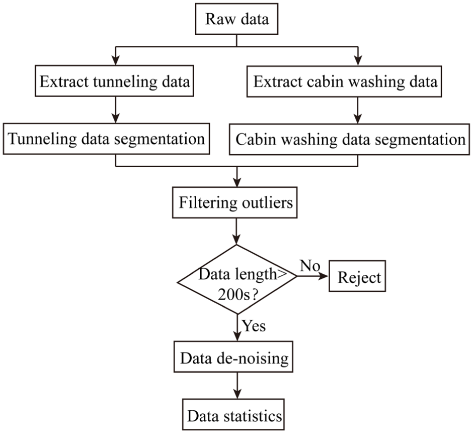
Data processing flow chart.
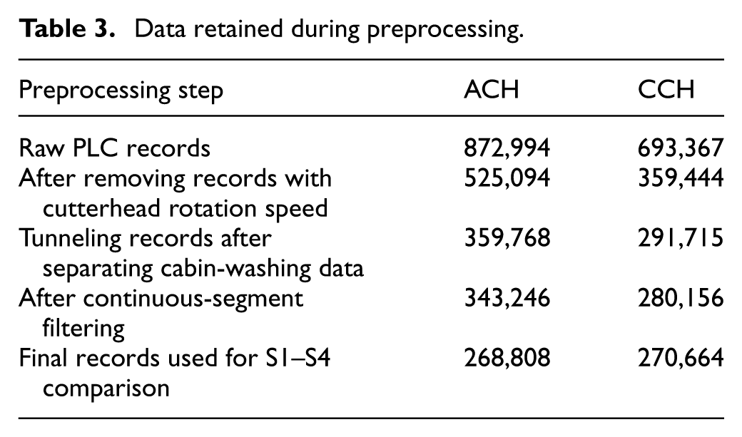
To improve data quality, the 3σ method is used to identify and exclude abnormal data points. Additionally, to reduce potential analysis errors from shorter time periods, data segments shorter than 200 s were excluded. Subsequently, the data for each period are denoised to minimize the impact of noise on the analysis results. To reduce high-frequency fluctuations in the PLC signals, the Savitzky-Golay filtering method was applied to the main tunneling parameter series within each continuous segment. The window size was set to five sampling points, corresponding to 100 s under the 20 s sampling interval, and the polynomial order was set to 3. The filtering was performed separately for each continuous segment to avoid smoothing across discontinuous tunneling periods. Finally, the preprocessed data are statistically analyzed. Specifically, the CCH has a total of 270,664 records, including 4152 tunneling sections and 2553 cabin washing sections, while the ACH has a total of 268,808 records, including 6064 tunneling sections and 1577 cabin washing sections (Table 3). The retained records consisted of 72,952, 27,870, 73,593, and 94,393 records for ACH in S1–S4, respectively, and 111,575, 28,392, 52,748, and 77,949 records for CCH in S1-S4, respectively. It should be noted that these section-level observations were used mainly to characterize the time-varying operational response of the machines under different strata and operational stages. Because they were obtained from continuous excavation sequences of the same machines, they were not treated as fully independent replicate samples for formal inferential analysis.
Data retained during preprocessing.
Tunneling state analysis of CCH
Tunneling parameters provide real-time feedback on geological information and changes in the tunneling state, and adjustments to these parameters result in corresponding changes in the equipment state. Therefore, by analyzing the tunneling parameters, the tunneling state of the shield machine can be assessed. During the initial stage of slurry TBM-driven tunneling, frequent stops are necessary for debugging and inspecting the shield machine to ensure the proper functioning of all systems. Additionally, continuous adjustments of the tunneling parameters are required to adapt to the formation conditions. As such, the data during 20–460 rings are selected for analysis. For CCH, the mud-cake cleaning and cutter replacement conducted around Ring 148 were treated as a key operational intervention in the present analysis. Therefore, the time-series response of the CCH is interpreted in two stages, namely the pre-intervention stage (Rings 20–147) and the post-intervention stage (Rings 148–460), so that the observed parameter variations can be understood in relation to both geological conditions and major operational changes.
The scatter plot of key tunneling parameters of CCH for each tunneling section is shown in Figure 6. Due to the high risk and long time required for opening the cabin of CCH, the strata with better stability would be selected to open the cabin for cleaning the mud cake and replacing the cutters at Ring 148. Rotation speed exhibited considerable fluctuation in S1 and S2, ranging from 0.85 to 1.25 rpm. Conversely, rotation speed variation in S3 and S4 was markedly lower, remaining largely stable between 1.1 and 1.2 rpm. Penetration of cutterhead is highly sensitive to geological conditions, cutter wear state, and the presence of mud cake on the cutterhead. Penetration in S1 and S2 strata ranged between 1 and 6 mm/r. After cutter replacement and mud cake removal at Ring 148, penetration increased significantly. In S3 and S4 strata, penetration fluctuated within a higher range of 8–16 mm/r. Advance rate, calculated as the product of rotational speed and penetration, largely mirrored the trend of penetration. Consequently, advance rates were relatively low in S1 and S2 strata, generally below 10 mm/min. After Ring 148, the advance rate increased significantly, reaching 10–20 mm/min. Furthermore, cutterhead torque exhibited distinct patterns across strata: fluctuating between 5000 and 20,000 kN·m in S1, increasing slightly and fluctuating between 7500 and 20,000 kN·m in S2 strata, respectively. While torque decreased significantly after the Ring 148 intervention, stabilizing around 10,000 kN·m in S3 and S4 strata. Extrusion forces were relatively high in S1 and S2, typically fluctuating between 35,000 and 45,000 kN. After Ring 148, thrust decreased substantially, fluctuating between 20,000 and 25,000 kN. Finally, Excavation chamber pressure behavior also varied stratigraphically. Pressure in S1 gradually increased with excavation distance, reaching 3.5 bar; remained stable at approximately 3.2 bar in S2; ranged between 3.0 and 3.5 bar in S3. Significant variation of excavation pressure occured in S4 strata, fluctuating between 2.5 and 3.5 bar.
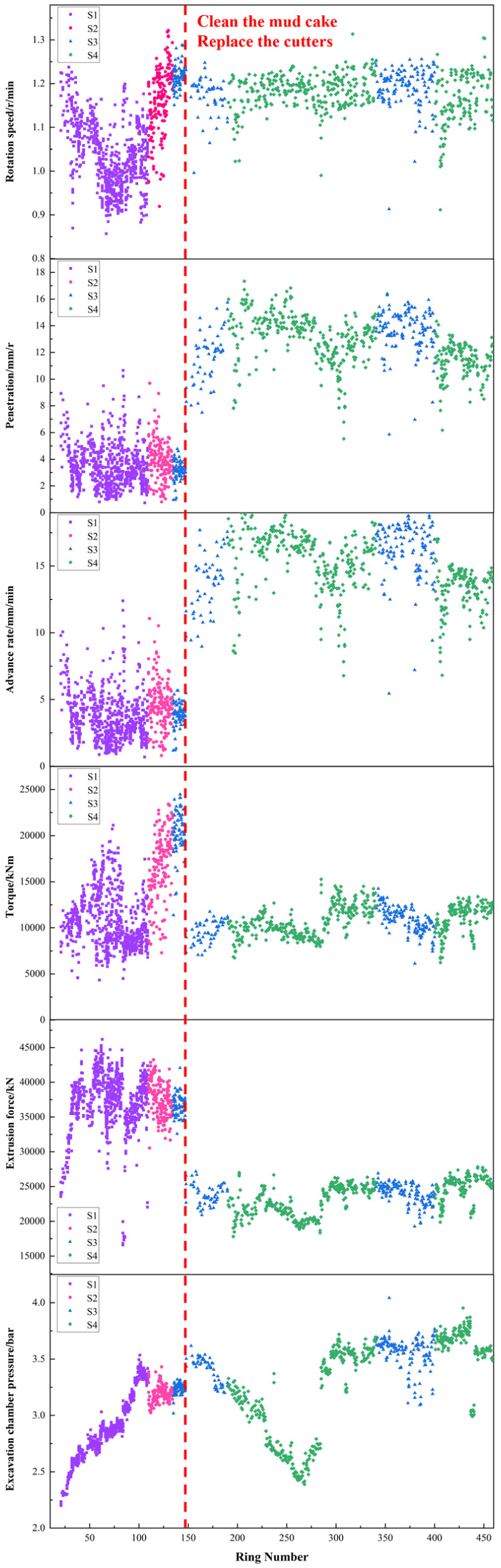
Variation law of the CCH tunneling parameters with time.
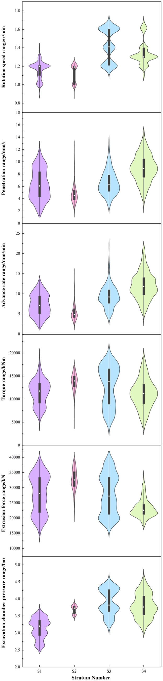
The distribution of six key tunneling parameters across strata S1, S2, S3, and S4 are presented in Figure 7 with violin plots. As for rotation speed, the S1 stratum exhibits the lowest overall rotational speed, with a median of approximately 1.0 rpm. Distribution in S2 is wider with a median near 1.15 rpm. S3 displays the highest median speed at around 1.2 rpm, while S4 maintains a median speed of approximately 1.18 rpm. In terms of Penetration, Penetration rate distributions in S1 and S2 strata are bell-shaped. In contrast, S3 exhibits a bimodal (hourglass-shaped) distribution. Median penetration rates follow the order S4 > S3 > S2 > S1. S3 and S4 strata maintain median rates near 12.5 mm/r, while S1 and S2 show significantly lower medians around 3–4 mm/r. The advance rate distribution trend across strata closely mirrors that of the penetration rate. Median advance rates also follow the sequence S4 > S3 > S2 > S1. S3 and S4 strata exhibit median advance rates of approximately 15 mm/min, compared to rates near 4 mm/min in S1 and S2. Furthermore, median torque magnitudes rank as S2 > S3 > S4 > S1. Torque is highest in S2, while values in S1, S3, and S4 show less variation relative to each other. S4 exhibits the narrowest torque variation range. As for extrusion force, forces in S1 and S2 are comparable, concentrated near 37,500 kN. Similarly, forces in S3 and S4 strata cluster around 25,000 kN. Extrusion forces in S1/S2 are significantly higher than those in S3/S4. While pressure distributions exhibit greater complexity with the rank S4 > S3 > S2 > S1. Pressure distributions are relatively dispersed (discrete) in S1, S3, and S4, while S2 shows comparatively less variation.
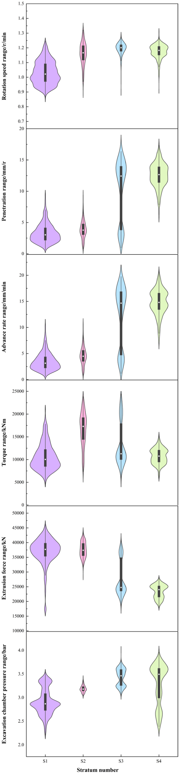
Variation law of the CCH tunneling parameters with stratum.
Tunneling state analysis of ACH
During the tunneling process of the ACH, several major operational interventions were implemented, and these events were treated as important phase-defining transitions in the present study. At Ring 143, the mud cake on the cutterhead was cleaned and the suction port was relocated forward to improve muck flow (Figure 8) However, this relocation also occupied the original position of the crusher, which increased the risk of blockage by large rock fragments. Therefore, at Ring 269, the suction port was restored to its original position. Later, when the ACH excavated the S4 strata, frequent blockage of the muck hopper by coarse rock fragments significantly reduced the advance efficiency. To address this problem, a single-roll secondary crusher equipped with limit plate and alloy teeth was installed at Ring 423 (Figure 9). Accordingly, the ACH tunneling process in this study was interpreted in multiple operational stages separated by the intervention at Rings 143, 269, and 423.
Slurry pump suction port forward transformation schematic diagram.
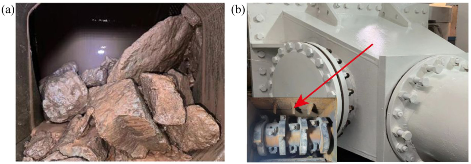
Add secondary crusher in ACH construction: (a) blockage of rock segment at quarry box and (b) structure of crusher.
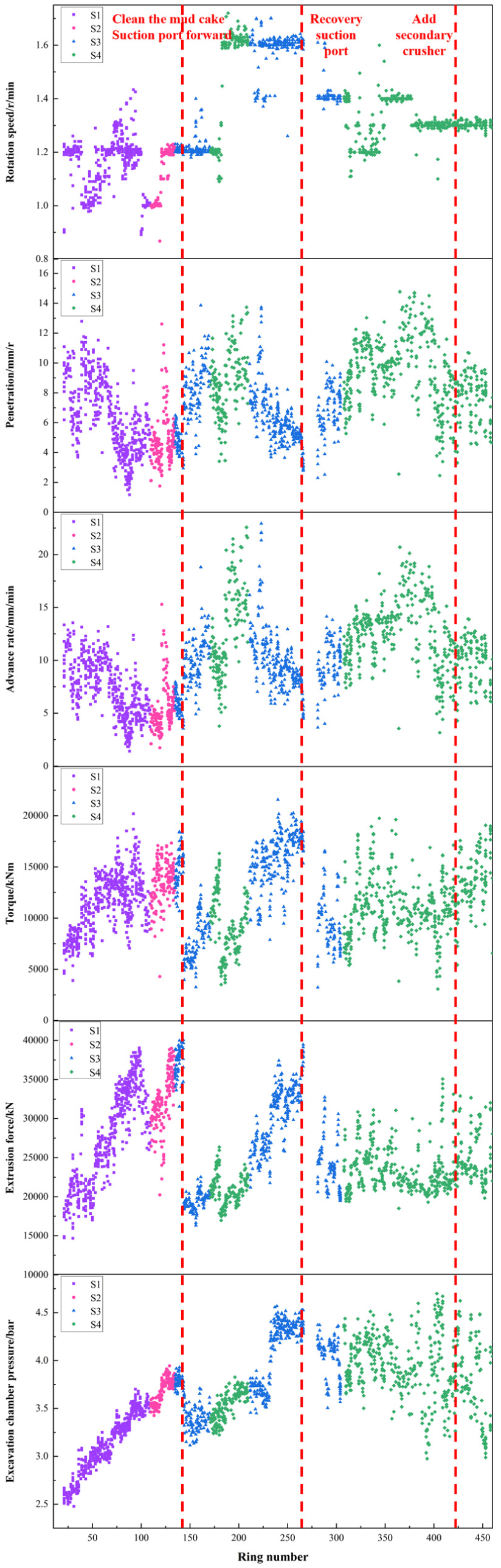
The scatter point variation curves of the tunneling data of the western line’s ACH from 20 to 460 rings are shown in Figure 10. The variation of ACH’s rotation speed in strata S1–S4 has been shown in Figure 10. In S1, the rotation speed fluctuates between 0.9 and 1.4 rpm. In S2 strata, it remained mainly within the range of 1.0–1.2 rpm. Following ring 143, the cutterhead rotation speed increased significantly. In S3 and S4, the speed stabilizes at approximately 1.6 rpm, apart from numerous discrete data points.
Variation law of the ACH tunneling parameters with time.
The penetration rate (ACH) exhibits significant fluctuations. In stratum S1, it shows a gradual decline from 12 to 2 mm. Penetration in S2 is typically maintained between 4 and 6 mm, with occasional instances of higher values. Within strata S3 and S4, penetration varies widely, ranging from 3 to 14 mm. This substantial variation is primarily attributed to cutter wear and cutter replacement activities.
The variation curves of the cutterhead’s advance rate across the four strata are shown in Figure 10. The advance rate in S1 and S2 is generally lower than that in S3 and S4. Specifically, the rate in S1 and S2 typically fluctuates between 3 and 12 mm/min. In S3, it ranges from 5 to 20 mm/min, while in stratum S4, the advance rate varies from 3 to 23 mm/min.
The cutterhead torque in S1 gradually increases with ring number, rising from 5000 to 20,000 kN. In contrast, torque in S2 typically varies between 10,000 and 15,000 kN. Following the clearance of mud cake at ring 143 and the forward of the suction port within S3 strata, the torque decreased sharply from approximately 15,000 kN to around 5000 kN. Subsequently, torque in S4 generally fluctuated between 5000 and 15,000 kN. However, upon entering the second S3 strata, torque increased significantly to approximately 20,000 kN. After the suction port was restored at ring 269, torque decreased to around 10,000 kN. In the subsequent S4 strata, torque exhibited wide fluctuations, ranging from 5000 to 20000 kN.
The extrusion force in S1 strata gradually increases with ring number, rising from 15000 to 40000 kN, which correlates with the formation situation of mud cake. Then, the extrusion force remained at around 30,000 kN in S2 strata and early S3 strata. After the mud cake was removed and the suction port was moved forward, the extrusion force rapidly decreased from 40000 to 20000 kN. In S4 strata, extrusion force stabilized between 20,000 and 25,000 kN. In second S3 strata, extrusion force increased with ring number, reaching 40,000 kN. After the suction port recovery at ring 269, extrusion force fluctuates between 20,000 and 30,000 kN in S3 and S4 strata.
In the S1 strata, excavation chamber pressure gradually increases with ring number, rising from 2.5 to 3.5 bar. Similarly, in the S2 strata, pressure exhibits a gradual upward trend, climbing from 3.5 to 3.8 bar. Following mud cake clearance at ring 146 and forward of the suction port, chamber pressure decreased from 3.8 to 3.4 bar. Subsequently, pressure resumed its gradual increase with ring numbers. The pressure rose further to 4.5 bar in the second S3 strata. After restoration of the suction port, chamber pressure exhibited significant fluctuations, oscillating between 3.0 and 4.5 bar.
The distribution of six key tunneling parameters of ACH across strata S1, S2, S3, and S4 are presented in Figure 11 in forms of violin plots. Regarding rotation speed, the order of median values is S3 > S4 > S1 > S2. In S1 strata, cutterhead rotation speed predominantly clusters around 1.2 rpm. S2 exhibits limited data points, primarily concentrated at 1.0 and 1.2 rpm. Three distinct rotational speed clusters emerge in S3 at 1.6, 1.4, and 1.2 rpm. In S4 strata, rotation speed peaks at 1.3 rpm, with secondary clusters observed at 1.6 and 1.2 rpm.
Variation law of the ACH tunneling parameters with stratum.
The penetration of ACH in the S1 strata exhibits a relatively discrete distribution across the range of 1–12 mm/r, with a median value of 6 mm/r. In S2 strata, penetration is predominantly concentrated between 2 and 6 mm/r, where the median value is 4 mm/r. Distributions for S3 and S4 formations demonstrate similar characteristics, both approximating a normal distribution. The median penetration rates for S3 and S4 strata are 6 and 8 mm/r, respectively, corresponding to their modal values.
The advance rate distribution trends in four strata generally align with the penetration distributions. In S1 strata, advance rates exhibit a relatively discrete distribution between 1 and 15 mm/min. While the advance rate in S2 strata clusters primarily around 5 mm/min. Advance rate in S3 strata basically shows a normal distribution except for a few peak anomaly points. Besides, advance rate in S4 follows a normal distribution ranging from 3 to 23 mm/min with a median of 13 mm/min.
The torque distributions for the S1 and S3 strata exhibit similar bimodal characteristics. In S1, torque clusters prominently at 12,500 and 8000 kNm, with a median of 12,000 kNm. The S3 formation shows clustering at 8000 and 17,500 kNm, with a median of 14,500 kNm. Within the S2 strata, torque values concentrate predominantly at 14,700 kNm. In S4 strata, torque follows an approximately normal distribution, with a mean value of 10,000 kNm.
As for extrusion force, the data distribution shows similar characteristics with wide variation range in S1 and S3 strata, clustering prominently at 20,000 and 35,000 kN. The average extrusion force in S2 strata is maximum at 32,500 kN. In S4 strata, the violin chart shows a trend of bottom wider and top narrow, which means that a large number of extrusion force concentrates at smaller value of 20,000 kN.
Excavation chamber pressure distribution is complex, where the violin shapes in four strata are totally different. Compared with S2 strata, the pressure distribution range of S1, S3, and S4 strata is wider. And the order of median values is S3 > S4 > S2 > S1.
Comparative analysis of two slurry TBM system configurations featuring conventional and atmospheric cutterheads
Comparison of tunneling parameters
Rotation speed
The rotation speed distribution of cutterhead in four different strata was compared and analyzed, as shown in Figure 12. In the S1 formation, the rotational speed range of the ACH is significantly wider than that of the CCH. The ACH achieved a higher average rotational speed (1.16 rpm) compared to the CCH (1.03 rpm). However, the CCH demonstrated greater rotational stability, with a lower standard deviation (0.078) versus the ACH (0.097). In the S2 formation, the ACH exhibits a wider rotational speed range than the CCH, but operates at a lower average speed (1.21 rpm vs 1.16 rpm). Across S3 and S4 formations, both cutter heads show similar rotational speed distribution patterns. However, the ACH maintains higher average speeds (S3: 1.43 rpm; S4: 1.34 rpm) compared to the CCH (S3: 1.19 rpm; S4: 1.18 rpm). Notably, the CCH demonstrates significantly tighter rotational speed clustering in these strata, with standard deviations substantially lower than those of the ACH.
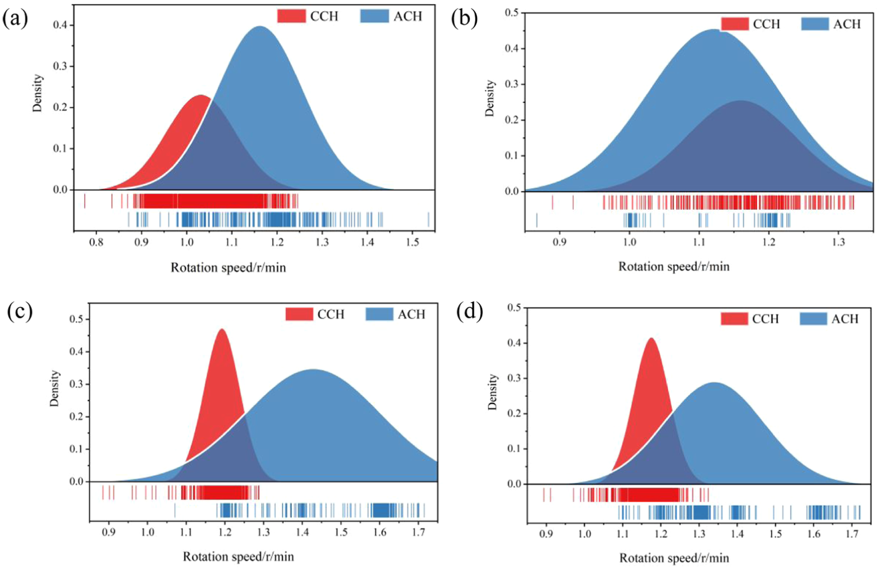
Comparison of rotation speed of CCH and ACH in four strata: (a) S1 strata, (b) S2 strata, (c) S3 strata, and (d) S4 strata.
Penetration
The penetration distribution maps of CCH and ACH in four strata are shown in Figure 13. In S1 strata, ACH exhibits a higher average penetration (6.3 mm/r) compared to CCH (3.32 mm/r). The wider standard deviation of ACH indicates a broader distribution range for its penetration, whereas CCH penetration values are more concentrated. In S2 strata, the penetration distributions of ACH and CCH are similar, with comparable average values (4.8 and 3.9 mm/r, respectively). Within the S3 formation, the penetration of ACH is relatively concentrated (average: 6.6 mm/r; SD: 1.96), while CCH penetration shows a wider distribution (average: 10.2 mm/r; SD: 4.84). Consequently, the average penetration of ACH is lower than that of CCH in S3. Finally, in the S4 formation, the penetration distribution trends of CCH and ACH are similar. However, CCH achieves a higher average penetration (12.6 mm/r) than ACH (8.94 mm/r).
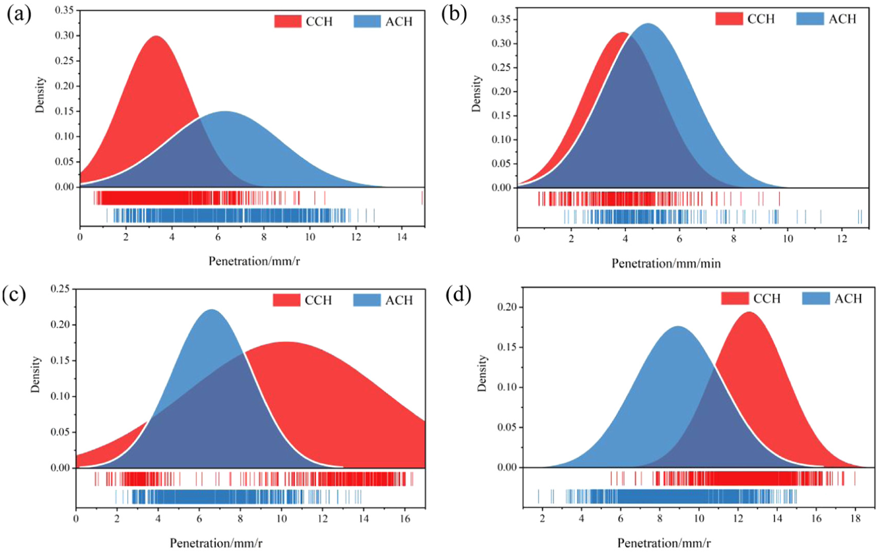
Comparison of penetration of CCH and ACH in four strata: (a) S1 strata, (b) S2 strata, (c) S3 strata, and (d) S4 strata.
Advance rate
The comparison of advance rate of ACH and CCH across four strata is shown in Figure 14. In S1 strata, CCH exhibits a relatively concentrated advance rate distribution, while ACH shows a dispersed distribution. The average advance rate of CCH (3.5 mm/min) is lower than that of ACH (7.2 mm/min). In S2 strata, the distribution trend of advance rate is basically same, with the average advance rate being close to 5 mm/min. In S3 strata, advance rate of ACH is relatively concentrated (average: 9.4 mm/min; SD: 2.8), while advance rate of CCH is widely distributed (average: 12.2 mm/min; SD: 5.8). Consequently, the average advance rate of ACH is smaller than that of CCH in S3 strata. Conversely, in S4 strata, advance rate of ACH is more dispersed, while advance rate of CCH is more concentrated. The average advance rate of ACH (12 mm/min) is smaller than that of CCH (14.8 mm/min).
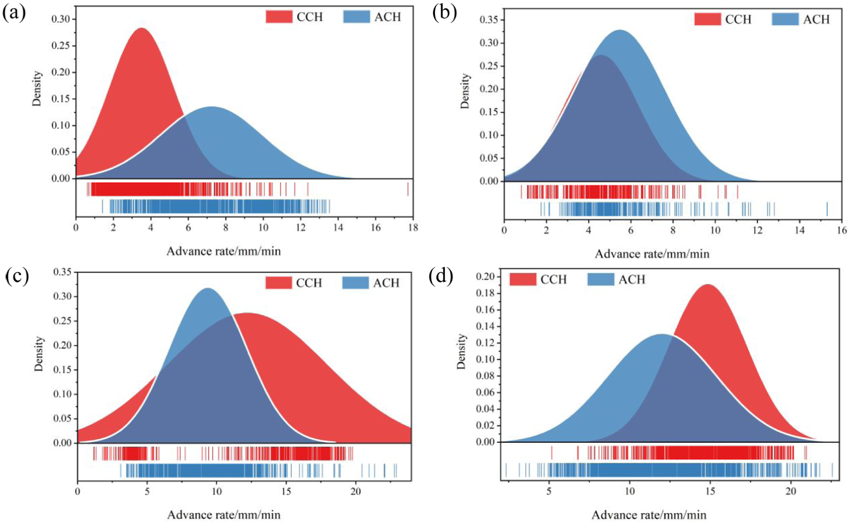
Comparison of advance rate of CCH and ACH in four strata: (a) S1 strata, (b) S2 strata, (c) S3 strata, and (d) S4 strata.
Torque
The torque distribution across the four strata is illustrated in Figure 15. In the S1 stratum, the torque distribution patterns of CCH and ACH are generally consistent. The average torque for ACH is 11,429 kN·m, slightly higher than that of CCH, which is 10628 kN·m. In the S2 stratum, the torque distribution of CCH is relatively dispersed, whereas that of ACH is more concentrated. The average torque values for CCH and ACH are 16,614 and 13,676 kN·m, respectively, with standard deviations of 3732 and 1986. In the S3 stratum, the torque distribution trends of CCH and ACH are similar, both averaging around 27,500 kN·m, though CCH exhibits a higher degree of data concentration. In the S4 stratum, the average torque values for both CCH and ACH are approximately 23,200 kN·m. However, the torque distribution of CCH is relatively concentrated, with a standard deviation of 2274, while that of ACH is more dispersed, showing a standard deviation of 3077.
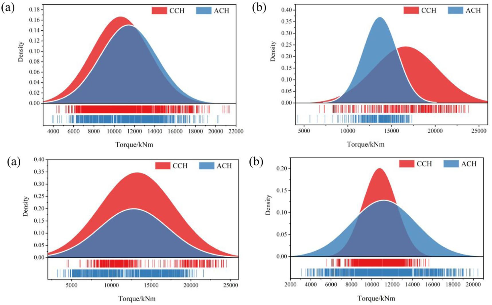
Comparison of torque of CCH and ACH in four strata: (a) S1 strata, (b) S2 strata, (c) S3 strata, and (d) S4 strata.
Extrusion force
The distribution of extrusion force between the CCH and ACH cutterhead across the four strata is compared, as shown in Figure 16. In the S1 strata, the compressive force distribution of ACH is relatively dispersed, while that of CCH is more concentrated. The average compressive force for CCH is 37,112 kN, higher than that of ACH at 27,801 kN. The standard deviation for CCH is 4495, which is lower than that of ACH at 6245. In the S2 strata, ACH again shows a more dispersed distribution, whereas CCH exhibits greater concentration. The average force for CCH is 37,563 kN, significantly higher than that of ACH, recorded at 32,525 kN. The standard deviation of extrusion force for ACH is 3675, compared to 2662 for CCH. In the S3 strata, the average compressive forces of ACH and CCH are similar, both around 27,500 kN, with CCH showing a higher distribution density around the mean. In the S4 strata, the average compressive forces of both cutterheads are also comparable, approximately 23,200 kN. However, ACH has a wider distribution range, with a standard deviation of 3078, compared to 2274 for CCH.
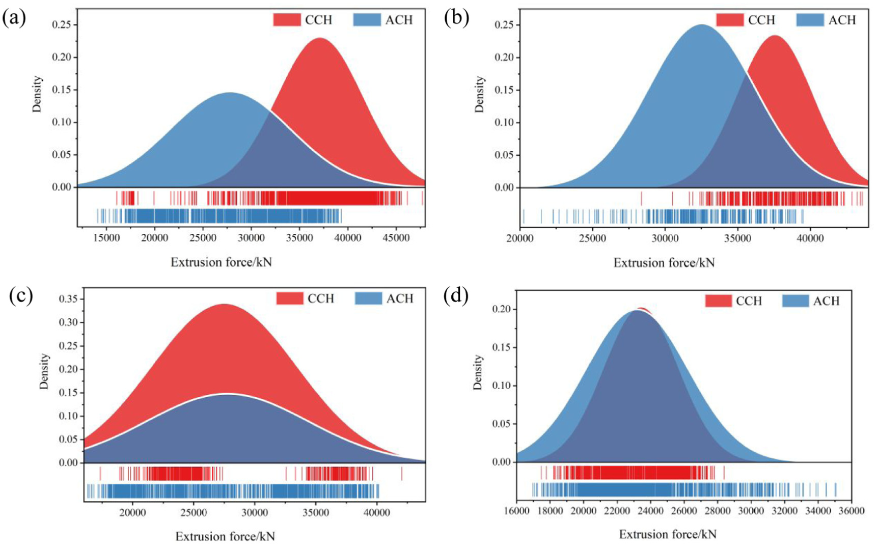
Comparison of extrusion force of CCH and ACH in four strata: (a) S1 strata, (b) S2 strata, (c) S3 strata, and (d) S4 strata.
Excavation chamber pressure
Figure 17 illustrates the pressure distribution in the excavation chambers of the CCH and ACH cutterheads across the four strata. In the S1 strata, both cutterheads exhibit the same range of chamber pressure, but their distribution patterns differ. The pressure in the CCH chamber follows an approximately normal distribution, symmetric around an average value of 2.91 bar. In contrast, the ACH chamber shows a higher average pressure of 3.14 bar, with an asymmetric distribution. In the S2 strata, the chamber pressures of CCH and ACH differ significantly. The average pressure for CCH decreases to 3.19 bar with a more concentrated distribution, while ACH has a higher average pressure of 3.69 bar and a more dispersed distribution. The standard deviation for ACH is 0.12, compared to 0.07 for CCH. In the S3 strata, the average chamber pressure of CCH is 3.43 bar, lower than that of ACH at 3.91 bar. The pressure distribution of CCH is relatively concentrated, whereas that of ACH is more dispersed, with standard deviations of 0.18 and 0.38, respectively. In the S4 strata, CCH again shows a lower average chamber pressure of 3.28 bar, compared to 3.80 bar for ACH. In this stratum, however, the standard deviation for CCH is 0.43, which is higher than that of ACH at 0.36.
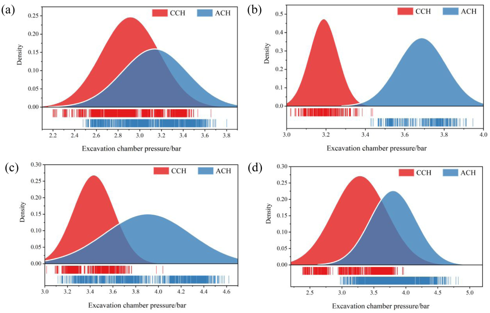
Comparison of excavation chamber pressure of CCH and ACH in four strata: (a) S1 strata, (b) S2 strata, (c) S3 strata, and (d) S4 strata.
Comparison of tunneling time
After completing the excavation of each ring, the shield machine needs to stop to assemble segments before excavating the next ring. This cycle repeats until the tunnel construction is completed. Therefore, the tunneling distance and cycle are often measured by the number of rings. For large-diameter shield tunnels, the width of each ring segment is typically 2 m. The construction time per ring consists of excavation time, segment assembly time, equipment maintenance time, and other factors. Therefore, the construction time per ring refers to the total time spent completing the construction of a ring, which is used to measure the tunneling efficiency of the equipment. The shorter the construction time per ring, the higher the tunneling efficiency.
Based on the collected tunneling data, the tunneling efficiency of the two cutterheads is analyzed using statistical methods. Therefore, in the present study, ring-level construction indicators were regarded as the main comparative units for formal efficiency evaluation, whereas the section-level PLC observations were mainly used for descriptive analysis of operational states and parameter evolution. Non-parametric tests have fewer assumptions regarding the data distribution and parameters, making them more suitable for data that do not meet the assumptions of normal distribution or when sample sizes are small. A non-parametric test method is applied to compare and analyze the tunneling efficiency of the two cutterheads for the data with complex distribution.
The Kruskal-Wallis test, a commonly used non-parametric method, is used to determine whether there are significant differences between groups of two or more continuous or discrete variables. The Kruskal-Wallis test is based on the H statistic, and the calculation method is shown in equation (1). The critical value is determined based on the sample size and significance level (typically a = 0.05). If H≥ the critical value, the null hypothesis (H0) is rejected, indicating a significant difference in the sample distributions; if H< the critical value, the null hypothesis (H0) is not rejected.
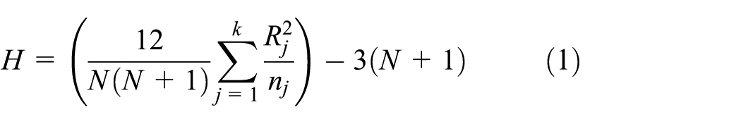
Where k is the number of groups of samples, N is the total number of samples, R j is the rank sum of the jth sample, n j is the sample size of the jth sample.
The result of the Kruskal-Wallis test for tunneling time per ring is shown in Figure 18. From the figure, it can be seen that for the S1 and S2 strata, there is no significant difference between CCH and ACH, but a significant difference exists in the S3 and S4 strata (p < 0.05). In the S1 and S2 strata, although ACH’s tunneling time per ring is shorter than CCH’s, the time spent on maintenance work is significant. Specifically, after each ring of tunneling, ACH requires maintenance personnel to enter the cutterhead to inspect the wear of the cutter bolts and check the patency of the flushing pipeline. Additionally, regular cutter inspections and replacements are necessary. Therefore, the construction time per ring for both CCH and ACH is similar. The S1 and S2 strata, located within the first 200 m of the tunnel, represent the running-in phase of the shield tunnel excavation. During this phase, the construction team must address and resolve a variety of equipment issues, such as installing ventilation systems and managing trailer traction. Furthermore, the mud cake formation on the cutterhead increases the tunneling time per ring in the S1 and S2 strata, making it longer compared to the S3 and S4 strata.
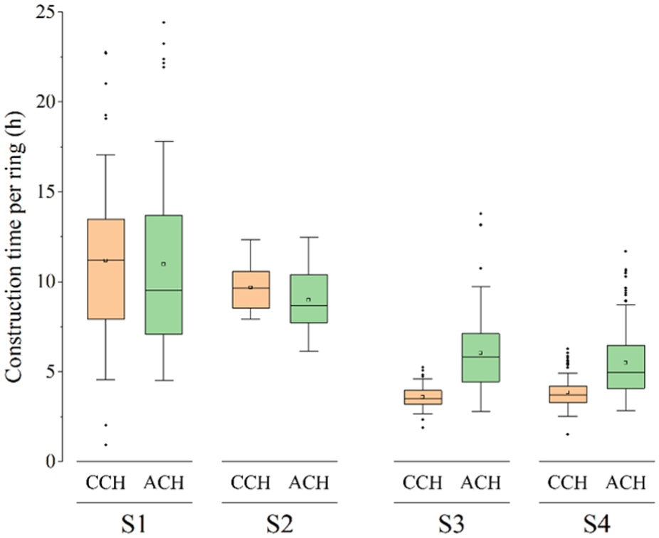
Comparison of construction time per ring under different strata.
Comparison of cutter wear and failure observations
It should be noted that the cutter wear data presented in Figures 19 and 20 are primarily qualitative observations of failure modes rather than quantitative comparisons of wear amounts across different strata. For the CCH, the excavation chamber could not be accessed before Ring 147 due to safety restrictions in the unstable S1 and S2 strata (soft soil with poor formation stability). Consequently, the cutter conditions observed at Ring 147 (Figure 19) represent cumulative damage from excavating through S1, S2, and part of S3 strata, rather than wear attributable to any single stratum. Given the varying lengths of these strata (as shown in Table 1), quantitative decomposition of wear contributions from each stratum is not feasible. Therefore, the present analysis focuses on the characteristics of failure modes (e.g. normal wear, eccentric wear, ring fracture, ring shedding) and their spatial distribution on the cutterhead.
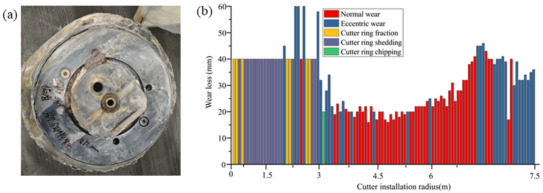
The failure situation of cutter: (a) normal wear of cutter on CCH and (b) the situation of cutter failure of CCH.
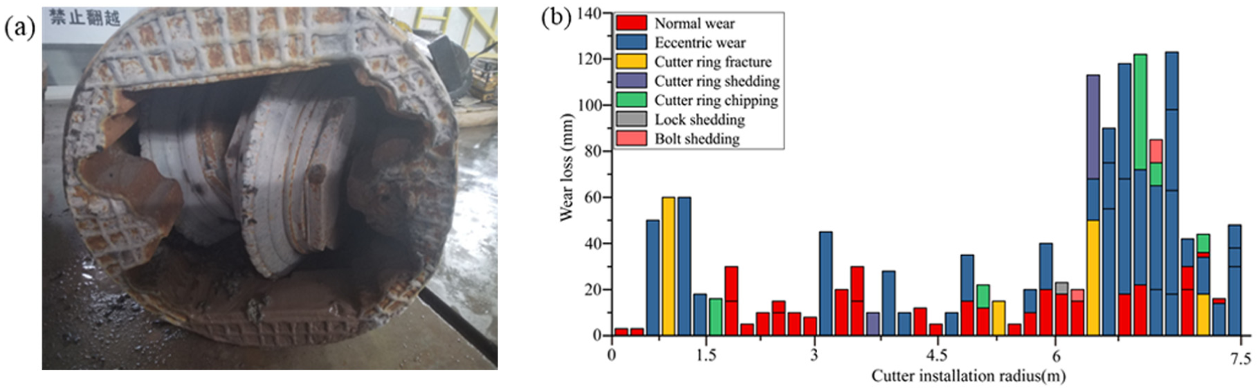
The failure situation of cutter: (a) bolt shedding of cutter on ACH and (b) the situation of cutter failure of ACH.
Due to the differences in cutter replacement modes, CCH and ACH exhibit significant variations in cutter failure. The stability of the S1 and S2 strata is poor, preventing access to the excavation chamber for cutter inspection and replacement. Consequently, the wear of the cutters on the CCH could not be checked or replaced in a timely manner. After entering the S3 strata, cutter inspection was conducted at ring 147, where it was found that all the disk cutters on the cutterhead were severely damaged. The failure modes of the disk cutters include normal wear, eccentric wear, cutter ring fracture, cutter ring shedding, and chipping, as shown in Figure 19(a). These failure modes are closely related to the geological conditions encountered. In the S1 and S2 soft soil strata, the primary challenge was mud cake formation and abrasive wear from silt and sand particles. However, the most severe damage—cutter ring fractures and shedding—occurred primarily within 3 m of the cutterhead center, which corresponds to the transition into the S3 hard rock stratum (medium and slightly weathered argillaceous siltstone with average strength up to 50 MPa). The sudden increase in rock strength and heterogeneity likely induced impact loads on the central cutters, leading to brittle fracture and ring shedding. This observation is consistent with previous studies reporting that cutter ring fractures are often associated with hard and heterogeneous rock conditions.14,15 Due to the extensive damage in the central area of the cutterhead, fractures and shedding of cutter rings were most prevalent, making it difficult to accurately measure the wear. To represent the severity of damage, the wear of all fractured or shed cutter rings is uniformly marked as 40 mm in Figure 19(b). Specifically, most cutter rings within 3 m of the cutterhead’s center exhibited fractures or shedding, while the remaining cutters showed significant eccentric wear, with wear levels approaching or exceeding the limit of the cutter ring. The cutter rings on the edge of the cutterhead experienced more severe eccentric wear, with wear amounts generally exceeding 38 mm. In contrast, although the proportion of abnormal cutter ring failures in the front area of the cutterhead was lower, the wear amounts were still considerable, generally above 18 mm, with the wear increasing toward the edge area. To restore the cutter’s rock-breaking performance during tunneling, all the disk cutters were replaced. Following the replacement, the CCH maintained a high advance rate during tunneling in the S3 and S4 strata.
During the tunneling process of ACH, where the cutters are installed in the cylinder, the breakage of cutter fastening bolts occurs frequently, as shown in Figure 20(a). The cutter replacement process for the ACH is shown in Figure 20(b). Due to the different installation method of the disk cutters on the ACH, in addition to the failure modes observed on the CCH, ACH also experienced lock shedding and bolt shedding. Thanks to the unique structural design of the ACH, cutter inspection and replacement can be performed in the radial arms of the cutterhead under atmospheric conditions, regardless of the geological conditions ahead. It significantly reduces the frequency of cutter ring fractures and shedding compared to the CCH. The dominance of normal and eccentric wear on the ACH, rather than ring fractures, can be attributed to two factors. First, the atmospheric cutterhead design allows for regular cutter inspections and timely replacements (as shown in Figure 20(b)), preventing the progression to severe fracture or shedding. Second, the different cutter installation method on the ACH (double-edged cutters with bolt connections) introduces a different failure mechanism—bolt loosening and shedding—which became the predominant failure mode, as shown in Figure 20(a). It should be noted that while the ACH exhibited less severe ring damage compared to the CCH, the frequent bolt failures nevertheless increased maintenance demands and downtime. As shown in the figure, the failure modes of the disk cutters on the ACH are primarily normal wear and eccentric wear. Compared to other areas, the cutter edge region experiences more frequent cutter replacements, with the failure mode primarily involving eccentric wear. During tunneling, the wear associated with normal wear is typically small, generally less than 20 mm.
Discussion
The Haizhuwan Tunnel Project consists of two parallel tunnels with similar geological conditions, which was constructed by a specific company, where the construction operations and staffing were unified. Two types of cutterheads, CCH and ACH, were employed in the two parallel tunnels. Compared to the CCH, the ACH features a thicker cutterhead structure and a smaller opening ratio, whereas the CCH has a narrower cutter spacing. Furthermore, the two shield machines also vary in equipment specifications. The CCH shield machine is equipped with a re-crusher, while the ACH shield machine incorporates a reinforced central flushing system at the cutterhead opening. These differences in cutterhead structure and equipment configuration likely contribute to the performance differences observed between the two shield machines during the tunneling process.
In the S1 and S2 strata, the highly cohesive nature of the soil leads to mud cake formation on both cutterheads, though their susceptibility to this issue differs. During initial excavation, the CCH experienced a rapid increase in extrusion force and cutterhead torque, accompanied by low penetration—suggesting quick mud cake buildup. In contrast, the ACH showed a slower rise in extrusion force and torque while maintaining relatively higher penetration. This improved performance may be related to the ACH’s central scouring system at the cutterhead opening, which uses high-pressure, high-speed water jets to break up the muck, potentially mitigating mud cake formation. Based on this observation, equipping the CCH with a similar central scouring system could be considered to help reduce mud cake risk, although this remains a hypothesis to be tested in future studies.
Additionally, relocating the suction port of the slurry pump forward appeared to enhance muck discharge in soft soil strata, as observed on the ACH. However, this approach may not be suitable in hard rock conditions, such as those in the S3 and S4 strata, where it could lead to blockages in the quarry box and slurry pump. In these hard rock environments, the ACH encountered challenges including rapid cutter wear, muck retention, and clogging. One possible explanation for the accelerated cutter wear is the relatively large cutter spacing of the ACH, which may reduce rock-breaking efficiency. While structural constraints limit how much the cutter spacing can be reduced, it often remains larger than the optimum value.
To address muck retention, increasing scouring pressure in accumulation-prone zones of the excavation chamber and raising slurry flow rate could facilitate better muck removal, as suggested by the observed improvement after the suction port modification on the ACH. For preventing blockages, installing a re-crusher ahead of the slurry pump proved effective on the CCH (as evidenced by the absence of clogging-related delays after its installation). Based on this positive experience, a similar device may be beneficial for the ACH, although this remains to be verified given the differences in muck discharge systems between the two machines.
Finally, the unique cutterhead design of the ACH allows for cutter replacement under atmospheric conditions, significantly enhancing operational safety. However, it should be noted that the initial purchase cost of the ACH is much higher compared to the CCH. Furthermore, upon completion of each ring excavation, maintenance personnel must enter the cutterhead to inspect the wear on cutter bolts and check the flushing pipelines. Regular cutter inspections and replacements are also necessary, leading to significantly higher maintenance costs for the ACH than for the CCH.
Limitations and future directions
It should be acknowledged that some of the interpretations and recommendations presented above are based on engineering reasoning and observational data rather than controlled experiments. The comparisons between CCH and ACH, while conducted under similar geological conditions, were not fully randomized, and other variables (e.g. operator decisions, maintenance schedules) could not be perfectly controlled. Therefore, the proposed explanations—such as the role of the central scouring system or cutter spacing—remain hypotheses to be tested in future studies. Controlled laboratory experiments or numerical simulations with isolated variables would be valuable to establish causal relationships. Additionally, the recommendations regarding increased scouring pressure and re-crusher installation should be validated through field trials before widespread adoption.
Conclusion
This paper compared the comprehensive performance of two slurry TBM system configurations featuring CCH and ACH under different strata in the Haizhuwan Tunnel Project. Firstly, the useful tunneling data during slurry TBM construction has been extracted and treated in a comparable scale. Then, the tunneling state of CCH and ACH under four different strata has been systematically analyzed, where rotation speed, penetration, advance rate, torque, extrusion force and excavation cabin pressure were taken as tunneling indicators. Furthermore, the tunneling parameters of the ACH and CCH in four strata were analyzed in detail. And the tunneling time and cutter consumption are also compared. Finally, the tunneling adaptability of CCH and ACH in four strata was comprehensively compared and analyzed. The following conclusions can be drawn:
Rotation speed, penetration, advance rate, torque, extrusion force and excavation cabin pressure are selected as tunneling performance evaluation indicators of slurry TBM, which reflect the tunneling efficiency and operational performance of the TBM, such as mud cakes and muck retention.
Under the harsh geological conditions, and intervention histories of the Haizhuwan Tunnel Project, the ACH-configured system showed relatively more favorable field performance in strata where chamber access was difficult and face stability was poor, whereas the CCH-configured system performed better in the hard-rock sections considered in this study.
Both CCH and ACH are prone to mud cake formation under unfavorable geological conditions with high viscosity, which significantly reduces tunneling efficiency. Therefore, enhancing the ability to predict and manage mud cake formation is essential.
In soft soil strata, advancing the suction port of the slurry pump can improve muck discharge efficiency and thereby enhance tunneling performance. However, this strategy is not suitable for hard rock strata, where the installation of a recrusher is crucial. The recrusher efficiently crushes rock chips, significantly reducing the risk of blockages caused by oversized rock fragments.
Overall, this case study provides engineering reference for understanding the field performance, operational trade-offs, and configuration implications of two representative slurry TBM system schemes featuring conventional and atmospheric cutterheads under broadly similar geological conditions and intervention phases. In the future, cabin-washing time, frequency, and sensitivity would be added to filtering rules for cutterhead type selection.
Footnotes
Handling Editor: Aarthy Esakkiappan
Funding
The authors disclosed receipt of the following financial support for the research, authorship, and/or publication of this article: This work was supported by the National Key R&D Program of China (Granted No. 2022YFC3802300), Postgraduate Scientific Research Innovation Project of Hunan Province (Granted No. CX20210211) and Independent Exploration and Innovation Program of Central South University (Granted No. 2021zzts0135).
Declaration of conflicting interests
The authors declared no potential conflicts of interest with respect to the research, authorship, and/or publication of this article.