






Abstract
This study investigates the structural behaviour of bolted joints that are intended to incorporate a fixed air-to-air refuelling probe inside an aircraft structure under both aerodynamic and operational loading. The CFD tool was used to estimate aerodynamic forces and compared them with the recommendations of MIL-A-8865B. Since the estimated aerodynamic and inertial loads were lower than the values suggested by the corresponding standards, the design of attachment joint was facilitated with the loading requirements of MIL-specified loading. An analytical framework was then formed to determine the reaction forces and moments at both hinged and fixed attachments under axial, radial, and combined loading conditions, using free-body diagrams and appropriate boundary constraints across all three directions. The methodology was numerically verified through a correlation between analytical model and high-fidelity stress mapping. These results provide a baseline for the development of high-reliability AAR systems and establish a framework for reduced equivalent stress, improved reserve factors and limited deformation. The proposed attachment could also be suitable for systems comprising slender, overhung structures, marine refuelling interfaces, robotic manipulators, and high-load bolted brackets. The significance attained through weight reduction, material selection, and durable joint architecture highlights the sustainability of bolted joint for next-generation mechanical system design.
Keywords
Introduction
Aerial refuelling, also called in-flight refuelling or air-to-air refuelling (AAR), is defined as transferring aviation fuel from a tanker aircraft to a receiver aircraft in flight. The receiver’s endurance, range, and operational flexibility are enhanced due to this operation. The aspect of AAR has been a vital capability in military aviation for nearly a century, enabling combat aircraft to extend mission duration and strategic reach. Its application enhances both the effectiveness and versatility of aerial missions.1,2
Bloy and Jouma’a 3 analysed induced loads on a Hercules receiver aircraft from a KC10 tanker using a wake roll-up and vortex lattice approach, showing strong sensitivity to the receiver’s vertical position relative to the tanker wake and a resulting reduction in directional stability under steady sideslip due to induced yawing moments. Schmidt et al. 4 reported the evaluation of a real-time simulation environment for helicopter air-to-air refuelling (HAAR) investigations. The importance of HAAR and the progress made in constructing a simulation scenario for HAAR in a research environment were discussed. López Herreros 5 worked on an image processing methodology to calculate the relative speed in air to air refuelling. The study involves a military transport aircraft (A400M), which uses a hose and drogue system to refuel aircraft and helicopters. The closure rate, or relative speed, between the tanker and receiver were calculated using virtual testing and on-board cameras. Hansknecht et al. 6 proposed an IP-based method to solve the air-to-air refuelling problem, design methodology for aircraft with reduced weight to optimize the fuel burn of feeder fleet. Kaushik et al. 7 considered the primary issues of drogue and probe detection for receiver aircraft pilots during AAR particularly at hazy and night conditions. This study is based on a drogue detection model with the Opto-Mechanical system which provided the better visual accuracy and navigation for detecting the port and real time performance of aerial refuelling. de Paula et al. 8 presented the methods and techniques developed by Brazilian Flight Test and Research Institute (IPEV) used for the HAAR qualification process between the helicopter H225M and the tanker KC-130H. In aerial refuelling, the probe-and-drogue (PDR) is considered the most challenging approach due to the flexible hose-drogue assembly’s dynamics and wind sensitivity, making probe-drogue contact difficult.9,10 The Probe and Drogue method engages a flexible hose which can be unrolled from a Refuelling Pod of the tanker plane.11,12 It is configured with structural rigidity to withstand aerodynamic stresses, and loads encountered during Refuelling operation. The Fixed Probe is designed considering both fitted and removed configurations. Schmelz et al. 13 worked on the design and assessment of Fighter Pilot Assistance Systems for AAR using Probe-to-Drogue-Equipment. Paulson et al. 14 investigated the challenges of in-flight refuelling for UAVs caused by communication latency. They developed a novel algorithm that uses tanker-centric stereo vision system to compute the UAV’s position and orientation, compensating for occlusion by transforming occluded areas into shadow volumes. Wang et al. 15 investigated docking success probability in probe–drogue aerial refuelling systems using probabilistic simulations that accounted for drogue motion, atmospheric disturbances, and actuation errors, showing that docking efficiency is highly sensitive to drogue positional variability and actuation accuracy.
Bolted joints are fundamental to aircraft structural integrity, governing load transfer and safety. Although their behaviour has been widely studied in conventional airframe applications, joint-level force and moment characteristics in probe-and-drogue refuelling system attachments remain largely unexplored. Tafheem and Amanat 16 investigated the bolt tension response of a flanged pipe joint subjected to bending using an ANSYS-based finite element model, performing a parametric study to quantify the influence of pipe diameter, flange geometry, bolt number, and bolt diameter on structurally effective bolt tension. The work carried out by Molnár et al. 17 focuses on the analysis and dimensioning of bolted joints, particularly in vehicles. The article addresses the uncertainty in load distribution among bolts in multiple bolted joints, which depends on the elastic deformation of the participating elements in the joints. Giannella et al. 18 formulated a three different Finite Element Method (FEM) modelling approach for the bolt connections of an automotive engine full 3D modelling of the bolt connections was preliminarily validated through a comparison with experimental test data available for the whole engine. Yousaf and Shafi 19 conducted FE simulations of double-lap protruding-head bolted joints under static tensile loading to simulate aircraft joint behaviour. Kapidžić et al. 20 modelled mechanically fastened composite-aluminium joints in aircraft structures under tensile and bearing loads. Kulak et al. 21 provided foundational design criteria for bolted and riveted joints covering fatigue, fracture, and static response.
Venkataramanan and Dogan 22 developed a numerical model to investigate the dynamic behaviour of a receiver aircraft during aerial refuelling, incorporating time-varying mass and inertia effects due to fuel transfer, tanker vortex-induced winds, and atmospheric turbulence, and proposed an averaging technique to capture the nonlinear influence of vortex interactions and turbulent motions within the standard aircraft equations of motion. Wang et al. 23 focused on the dynamic control problems of relative position holding and velocity holding conditions during the refuelling phase of Autonomous AAR missions. Zhu and Meguid 24 employed a finite element–based dynamic model using a computationally efficient three-noded curved beam element to simulate an aerial refuelling hose–drogue system, demonstrating that vortex-wake effects strongly influence system dynamics, with pronounced orbiting behaviour observed in shorter hoses that diminishes as hose length increases. Wang et al. 25 addressed the safety challenges present in UAV probe-drogue autonomous aerial refuelling. They developed a method using real-time docking success-probability estimation and docking reachability calculation. By considering the drogue’s location and UAV dynamics, algorithms designed for success-probability estimation and reachability calculation, ensuring safe docking. Sun and Duan 26 worked on hybrid algorithms on combining Pigeon-Inspired Optimization (PIO) and lateral inhibition (LI) for image matching in AAR. Jurkovich and Hummer 27 applied computational practices in analysing the tanker/receiver applications. Real-time aircraft flight data were used here to demonstrate the accuracy of Computational Fluid Dynamics (CFD) simulations in capturing the moments and delta forces acting on a tanker aircraft by proximity to a large receiver plane. To replace flight testing with a ground-based flight simulator aerodynamic model, Lofthouse and Nathan 28 simulated a potential aircraft numerically to generate aerodynamic coefficients. Here, the CFD simulations are illustrated over a B-52 receiver aircraft which is in aerial refuelling formation with a KC-135 tanker. It was concluded that it is possible to extract the necessary moment and delta force of the receiver and tanker aircraft, required in the simulations of ground-based flight models. Lee et al. 29 investigated the stereo vision pipeline and validated to perform pose estimation for AAR with a novel ground experiment. Bardell 30 analysed the impact of in-flight refuelling on the payload–range envelope of multirole tanker transport aircraft using the Breguet range equation combined with a simplified fuel-budget model for towline and trail missions. The study showed that refuelling operations significantly reduce available payload and range, highlighting the need for pre-mission performance assessment. Case studies demonstrated close agreement with published data, validating the approach for mission planning. A detailed comparative review of prior studies is consolidated in Table 1.
Comparative summary of prior studies and research gaps.

A significant amount research on the fixed refuelling probe attachments has primarily focused on baseline structural layouts, with emphasis on static strength verification, local stress assessment, or isolated aerodynamic loading effects. While these studies provide useful benchmark configurations, they largely treat structural, aerodynamic, and durability considerations in isolation and offer limited insight into integrated load transfer behaviour and long-term performance under realistic operational load combinations. The existing literatures refers to a traditional design concept of fixed refuelling probe attachments, in which the major concepts are hinged and fixed joints combinations. It however, gives scarce information on long term durability, structural reliability, and effective transfer of loads in different aerodynamic and operational conditions. These limitations highlight the need for an integrated design methodology, particularly for retrofit applications in lightweight combat aircraft, where structural compatibility and weight efficiency are critical. The present study addresses these gaps through a unified and fully integrated development framework by incorporating CFD-based aerodynamic load derivation under operational flight conditions, a closed-form analytical force–moment methodology for hinged and fixed interfaces using a propped-cantilever free-body model validated through global equilibrium, iterative three-dimensional finite element analysis (FEA) under combined axial, lateral, and inertial loading, and material as well as geometric optimization based on Reserve Factor (RF) evaluation, verified against MIL-A-8865B docking requirements to ensure structural integrity and performance reliability.
Design methodology
The design of the fixed air-to-air refuelling probe is evolved according to the operational and safety requirements of the receiver aircraft, as defined by NATO, MIL, and SAE Aerospace, with the probe–drogue interface, clearances, installation envelopes, structural loads, and testing requirements outlined mainly by STANAG-3447 and MIL-F-38363B. Following these standards, the overall design and evaluation methodology is first presented as a flowchart in Figure 1, and a representative fixed probe configuration suitable for combat aircraft, developed using this methodology with a retrofit approach involving localized structural modifications to the front fuselage, is illustrated in Figure 2.

Flow chart for the retrofit design of fixed refuelling probe.

Design concept of a typical fixed refuelling probe.
Conceptual design loads
Based on the flight envelope, the structural loads are estimated; load factor limits at each phase of flight are determined as per military standards. In the present study, the attachment joints of fixed refuelling probe are designed primarily considering the refuelling loads as specified in MIL-A-8865B. Further, the efficacy of joint design is validated for other operational loads such as aerodynamic, fuel pressure, torsional, shock, impact, vibration, acceleration, inertial, and fatigue. Refuelling directional loads with respect to various case studies are interpreted in the above Table 2.
Case study description with appropriate directional loads.

Forces and moment prediction of refuelling probes in light weight fighters
The forces and moments acting on the probe were evaluated based on the operational loads experienced at the probe tip. Primary loads include refuelling-induced axial compression during engagement, tensile loads during disengagement, and radial forces arising from the circumferential contact between the drogue and probe, along with combined radial–axial effects. Secondary loads are attributed to aerodynamic and dynamic influences during flight. Because the magnitude of the resulting moments depends on the probe’s inclination in the YZ plane, appropriate attention is given to its angular positioning. A retrofit design for a fixed refuelling probe, recommended for a Lightweight Fighter (LWF), is adopted as shown in Figure 3(a). With minor structural modifications, this configuration can be integrated effectively while maintaining a lightweight and efficient design. The probe is mounted on the port side, positioned h1 mm above the DEP to fulfil the clearance criteria specified in STANAG-3447. The structure is secured via two connection points, ‘C’ (Hinged Joint) and ‘D’ (Fixed Support), which work in tandem to ensure forces are transferred through the structure along a deterministic load path. The estimation of forces and moments at these joints is detailed using the free-body representation and force resolution along the principal coordinate system is presented in Figure 3(b) and (c), where Joint ‘C’ resists only two force (

Fixed refuelling probe for a light-weight fighter: (a) retrofit design scheme, (b) free body diagram of the refuelling probe attachment, and (c) loading of the probe with force resolution along the principal coordinate system.
First, the resultant radial force FR at the tip is resolved into global vertical and horizontal components based on the load inclination


To align these forces with the probe’s inclination angle


Here,
The equilibrium of forces in the local coordinate system is defined by setting the sum of all forces in the x′, y′, and z′ directions to zero:


Where FC and FD represents the reaction forces at joint C and joint D, respectively.
For the hinged Joint ‘C’, all axial loads are assumed to be transferred to the primary structural attachment at Joint ‘D’ to prevent kinematic binding. Therefore

This provides mathematically rigorous transition from static equations directly into the boundary conditions that define the deterministic load path. Summing moments about the fixed joint ‘D’ (


Furthermore,

By treating the reaction
The internal moment at a distance x from the fixed end is:

In aircraft, the hinge at ‘C’ is a rigid attachment. This means the probe cannot ‘bend’ or ‘deflect’ at that specific point. Mathematically, the vertical deflection at C

Tip load term;
Reaction term;
The redundant force


Vertical Hinge Reaction

Here, ‘1’ represents the base reaction required to support the load if there were no leverage. The

Similarly, the lateral reaction

Bending Moment at Fixed joint D (

Vertical Shear Reaction at Joint ‘D’


Global Coordinate Transformation using the inverse relation of rotation angle
Summary of forces and moments at the hinged and fixed joints.

Figure 4 illustrates the complete spatial representation and free-body layout used to analyse the fixed refuelling probe under combined refuelling and aerodynamic loads. The figure resolves the load-transfer behaviour through three principal projections to capture the probe’s full three-dimensional response. Figure 4(a) provides the schematic free-body diagram of the refuelling probe assembly, defining longitudinal segments and spatial offsets for structural load derivation. The structural integrity of the refuelling probe is evaluated by idealizing the assembly as a 3D fixed-base frame (A-B-C-D), constrained at the structural root (Point D). Longitudinally, the geometry comprises a 513.25 mm forward mast (A-B), a 513.25 mm cranked transition (B-C), and a 1000 mm root attachment segment (C-D). Relative to the mounting axis, the probe tip (Point A) exhibits a lateral offset of 344.7 mm and a vertical offset of 481 mm. Due to this critical spatial eccentricity, the application of the MIL-A-8865B specified orthogonal tip loads generates a severe combined-loading environment. The offset distances function as moment arms, effectively translating the extreme operational tip forces into complex bending and torsional moments acting upon the attachment joints (C and D) and across the primary mounting interface.
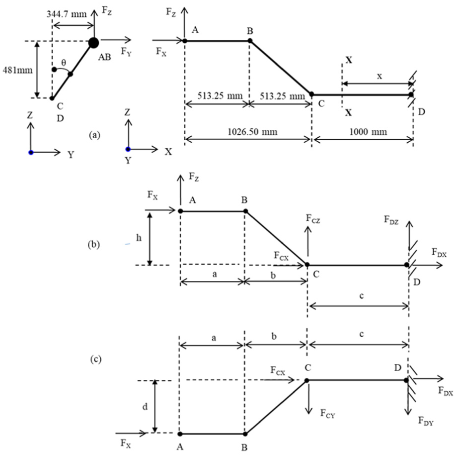
Structural layout and spatial load resolution of the fixed refuelling probe: (a) schematic free-body diagram of the refuelling probe assembly, (b) longitudinal side-view, and (c) transverse end-view.
Figure 4(b) presents the longitudinal side-view, indicating the probe’s statically indeterminate propped-cantilever configuration with a hinged support at C and a fixed support at D. The overhang and internal span are the major moment arms responsible for generating in-plane bending moments (pitching and yawing) and shear reactions transferred through the two joints. Figure 4(c) provides the transverse end-view in the YZ plane. It defines the vertical and lateral offsets between the probe tip and the mounting axis. These offsets couple with local shear forces to create a torsional (roll) moment, which must be resisted by the fixed bracket. Together, these projections establish a clear geometric and mechanical understanding of all load paths (axial, shear, bending, and torsional) forming the analytical basis for subsequent finite-element modelling and joint-reaction evaluation.
The operational limit loads acting on the refuelling probe nozzle (Point A) are derived in accordance with the MIL-A-8865B standard. These encompass fundamental load cases including axial compression, axial tension, and radial forces. To establish the ultimate design loads for the structural evaluation, a standard aerospace Factor of Safety (FoS) of 1.5 is applied to the initial limit loads. A summary of these governing load conditions is presented in Table 4. Under axial loading along the probe axis, the fixed support at Point D provides the primary axial reaction force and the resisting moments required to maintain static equilibrium. The hinged support at Point C serves a simpler kinematic role, providing the normal (radial) reaction forces necessary to prevent lateral displacement perpendicular to the probe axis.
Applied design load conditions.

To establish the structural equilibrium of the refuelling probe assembly, an applied compressive load of 13,350 N is directed along the longitudinal X-axis at the nozzle (Point A). The structural response was evaluated under varying load conditions (compressive, tensile, and radial) governed by MIL-A-8865B specifications, incorporating the standard ultimate FoS of 1.5. The resulting reaction forces and moments presented in Table 5 were derived based on the specific kinematic boundary conditions of the probe: a hinged support at Point C and a fixed support at Point D. Under axial loading along the probe axis, the fixed support at Point D provides the primary axial reaction force and the resisting moments required to maintain static equilibrium. The hinged support at Point C serves a simpler kinematic role, providing the normal (radial) reaction forces necessary to prevent lateral displacement perpendicular to the probe axis. For spatial load distribution, axial forces act purely along the x-axis
Reaction forces and moments for compressive and tensile loads in the ‘X’ axis.

FEM methodology
The 1D analytical model serves as a preliminary design and load decomposition tool, developed to estimate reaction forces and bending moments at the hinge and fixed joints under multiple loading conditions. The structural performance of the probe geometry was examined through finite element analysis, as shown in Figure 5. The analysis was built using a one-dimensional beam element framework, providing a practical and computationally efficient approach for capturing the probe’s global structural response under load. Instead of simple linear elements, a quadratic mesh arrangement with three nodes per element was adopted. Each node in the model was assigned Six degrees of freedom, comprising three translational and three rotational components. This configuration allowed the model to record the entire range of displacements and rotations expected under the investigated loading conditions. The boundary conditions were defined to realistically represent the kinematic constraints of the refuelling probe installation: the directional limit load was applied at the nozzle (Point A), while Joint C was modelled as an ideal hinged support (transferring only radial and shear loads with no moment resistance) and Joint D as a fixed support (resisting axial loads, pitching, and yawing moments). Several loading scenarios were examined by applying radial, tensile, and compressive forces at different radial orientations from 0° to 360°, including various combined loading cases derived from MIL-A-8865B to replicate severe refuelling situations. This approach provided an efficient numerical model, and the resulting internal forces and bending moments were numerically verified against the one-dimensional analytical equilibrium calculations to ensure mathematical consistency prior to 3D evaluation.

Discretization of refuelling probe 1D geometry in FE tool.
Design considerations for 3D model
A detailed three-dimensional model of the refuelling probe assembly comprising the primary probe components (nozzle, weak link, and probe mast) and the structural interfaces (mounting bracket and bolted connections) was developed in CATIA to facilitate accurate structural evaluation. The model was then discretized, incorporating the relevant boundary conditions, and analysed using ANSYS software. This 3D model accurately captures the precise geometry of the components and allows the application of localized spatial loading conditions across all three coordinate axes (X, Y, and Z). Multiple design concepts were explored for integrating the refuelling probe assembly with the aircraft interface bracket. The model representations of the fixed refuelling probe, as shown in Figure 6, illustrate the detailed engineering considerations and precise design features incorporated to meet functional and structural requirements.

CAD model of the fixed refuelling probe with details.
The one dimensional analytical model defines the global load path and reaction equilibrium used as input boundary conditions for the three dimensional finite element model. The FEM results, in turn, numerically verify the analytical predictions and reveal localized stress behaviour that cannot be captured in 1D analysis. Concept 1 connects the probe assembly to the bracket using clamps and M12 bolts, allowing it to withstand compressive, tensile, and radial loads during engagement with the refuelling drogue while ensuring smooth load transfer and reduced stress concentrations. Concept 2 introduces keyways and flanges on the probe mast and bracket to prevent slip and rotation, with six pre-tensioned M12 bolts providing improved stiffness and joint stability. Concept 3 employs a double-shear joint with a single large-diameter shear bolt and bushings, along with keyways and flanges for proper alignment, promoting superior load distribution and durability. For numerical evaluation, the model was meshed using tetrahedral elements with sizes ranging from 1 to 5 mm, and the bracket to structure interface was fully constrained to represent the actual fixed support condition. Loading conditions, mapped from the verified one-dimensional analysis involving radial, tensile, and compressive forces and their combinations, were applied across relevant radial angles. Bolt pretension was included at each connection to represent realistic assembly stresses.
Material considerations
The materials selected for the fixed refuelling probe assembly components are listed in Table 6, along with their mechanical properties. These properties remain uniform across all initial design configurations. In a subsequent design iteration, alternative materials were assessed for each component to evaluate mass reduction, stress intensity, and deformations under three critical combined load conditions: compression coupled with radial loads at orientation angles of 135°, 180°, and 225°. Furthermore, the ultimate tensile strength (UTS) and yield strength (YS) of the alternative materials were compared against the base materials to determine the overall performance and structural resilience of the probe assembly under peak operational stresses.
Material properties for various refuelling probe components.

Estimation of aerodynamic loads for CFD solver
The structural layout of a fixed air-to-air refuelling probe is influenced by two distinct load paradigms: continuous aerodynamic pressures encountered throughout the flight envelope, and transient, high-magnitude operational forces generated during probe-drogue engagement. While the operational docking loads prescribed by the MIL-A-8865B standard are required to govern the ultimate static strength and maximum stiffness of the attachment joints, the Computational Fluid Dynamics (CFD) analysis plays an equally indispensable, dual-role in the holistic design methodology:
Baseline spectrum: The aircraft operates in non-refuelling flight regimes for the vast majority of its service life. The CFD-derived aerodynamic loads provide the continuous baseline loading spectrum required for high-cycle fatigue, durability, and vibration-induced stress assessments.
Superposition for combined loading: During the engagement phase, the structural joints must withstand the operational docking impact simultaneously with aerodynamic drag and side-slip forces. The CFD analysis provides the highly accurate, multi-axial aerodynamic vectors (Fx, Fy, Fz) required to create an accurate superposition of forces for the combined 3D loading cases in the finite element model.
Aerodynamic penalty assessment: The integration of a massive retrofit cantilever structure alters the local flow field. The CFD analysis guarantees that the probe mast does not generate unacceptable drag penalties, severe buffeting, or adverse vortex shedding that could interfere with downstream control surfaces or engine intakes.
To balance computational cost with local accuracy, only the forward fuselage and the fixed refuelling probe were modelled with high fidelity. Downstream aerodynamic surfaces (wings, fins, and empennage) were omitted, as their influence on the local upstream flow field around the probe is negligible. No geometric approximations were made to the probe surface; all coordinates, tip geometries, and inclination angles were modelled exactly as per design specifications to capture fuselage-induced flow interference. The aerodynamic load estimates were performed using steady-state Reynolds-Averaged Navier-Stokes (RANS) computations via the CFD++ solver. The probe surface was segregated into discrete area strips (as illustrated in Figure 7) to compute the distribution of forces and moments, which were subsequently transformed into the probe-based local coordinate system for structural analysis. A rigorous grid generation strategy was employed using ICEM-CFD. For the forward fuselage and probe assembly, an unstructured tetrahedral-prismatic mesh was constructed to precisely depict the pressure distribution and local flow effects near the attachment locations. The final computational domain consisted of approximately 9.27 million elements, comprising 0.2 million triangular surface panels and 1.6 million tetrahedral volume elements in the far-field. To accurately capture boundary layer separation and adverse pressure gradients, the near-wall region was resolved using 38–45 anisotropic prismatic layers. The first-layer cell height was targeted at 0.01 mm to maintain a non-dimensional wall distance of y+ < 1, ensuring the viscous sublayer was fully resolved. A grid convergence study across three mesh densities (4.2M, 6.8M, and 9.27M elements) yielded a Grid Convergence Index (GCI) variance of only 1.8% between the medium and fine grids, confirming the 9.27M element mesh operates within the asymptotic range of convergence.

(a) Surface mesh encompassing the fuselage with a fixed refuelling probe, (b) area strips designated for load assessment on the probe, and (c) volume mesh cross-section along the probe.
Turbulence closure was achieved using the one-equation Spalart-Allmaras (S-A) model. The S-A model was selected for its proven robustness in external aerospace aerodynamics. It is specifically calibrated for boundary layer flows subjected to adverse pressure gradients, making it ideal for predicting drag and side loads on cylindrical, mast-like structures. Furthermore, the model has a proven legacy of validation for predicting flight loads on this specific fighter platform. The simulations were conducted with the probe and fuselage surfaces prescribed as adiabatic, no-slip viscous walls. The outer domain was treated with characteristic-based far-field inflow/outflow boundary conditions to prevent artificial wave reflections during transonic and supersonic evaluations. Convergence was strictly monitored; simulations were validated only when residuals for all governing equations decreased by at least five orders of magnitude (10−5) and integrated aerodynamic forces stabilized within a 0.5% variation threshold over the final 10% of iterations. The aerodynamic loads were evaluated across a matrix of extreme flight parameters representing peak dynamic pressure conditions, summarized in Table 7. This envelope captured variations in Mach number (0.95 and 1.2), Angles of Attack (−7° to +19°), and Angles of Sideslip (−6° to +6°).
Cases for computation of aerodynamic loads.

Following the CFD evaluations, the peak resultant aerodynamic load (derived at Mach 0.95 at Sea Level) was calculated at approximately 4000 N. Even with the application of a conservative 50% environmental uncertainty factor to account for peak gusts and rapid roll manoeuvres (yielding an ultimate aerodynamic design load of 6000 N), this value remains significantly lower than the 13,350 N ultimate operational load prescribed by MIL-A-8865B. Consequently, while the CFD results are vital for fatigue and combined-load superposition, the MIL-standard refuelling impacts definitively govern the static structural sizing of the attachment joints.
CFD analysis of probe section with aerodynamic loads
The CFD simulations quantified the aerodynamic force components acting on the probe mast across the operational envelope. To ensure compatibility with the structural reaction model, global forces were transformed into the local mast coordinate system (x′, y′, z′).
As illustrated in Figure 8, peak aerodynamic forces were established at 4000 N for both longitudinal drag (Fx′) and lateral shear (Fy′), with a 3200 N resultant in the transverse (Fz′) axis. The sinusoidal variation observed in the lateral (Fy′) and transverse (Fz′) profiles reflects the influence of the fuselage-induced flow field and angle-of-sideslip (AoSS) fluctuations across the 360° engagement envelope. While longitudinal drag remains relatively stable, the significant peaks in Fy′ identify it as the primary structural driver. Unlike axial loads, this lateral component acts normal to the probe’s longitudinal plane, inducing maximum bending and torsional moments at the attachment interface. This localized resolution ensures that the subsequent finite element analysis (FEA) accounts for the critical vector superposition at the 225° orientation, providing a mathematically rigorous baseline for structural optimization compared to global airframe-axis loads.

Maximum total load on the probe mast transformed in to local coordinates: (a) longitudinal (Fx′), (b) lateral (Fy′), and (c) transverse (Fz′).
Estimation of inertial loads
To demonstrate the application of the derived analytical framework, the inertial reaction loads were calculated for an 8 g limit load factor, representing a severe symmetrical pull-up manoeuvre for the Lightweight Fighter. The 18.8 kg overhung assembly comprising the nozzle (2.8 kg), weak-link (4.0 kg), and mast/boom (12.0 kg) was distributed into two discrete components to accurately model the inertial leverage: a 6.8 kg concentrated tip mass and a 12.0 kg distributed mast mass. Under the 8 g load factor, these components generate downward inertial forces of Fz = 533.7 and 941.8 N respectively, yielding a total downward inertial load of 1475.5 N.
Applying the specific geometric parameters of the retrofit design tip overhang (a + b) = 1.0265 m, main span c = 1.0 m, and lateral tip offset d = 0.345 m, the Principle of Superposition was employed to combine the reactions of the tip load and the mast centre of gravity. To maintain tangential deflection compatibility (δc = 0) at the hinged support, Joint C reacts with an upward shear force of 2316.0 N, while the fixed root at Joint D reacts with a downward shear of 840.5 N, a peak pitching moment of −280.0 N m, and a torsional moment of 184.0 N m induced strictly by the lateral spatial offset of the tip assembly. Critically, when benchmarked against the ultimate aerodynamic loads (4000 N lateral) and the severe STANAG 3447 docking conditions (13,350 N ultimate axial compression), the inertial forces are found to be significantly lower in magnitude, confirming that dynamic engagement rather than flight manoeuvre governs the ultimate structural design criteria of the attachment brackets. Table 8 provides mass distribution of the refuelling probe assembly. The 18.8 kg overhung subtotal is used exclusively for inertial bending analysis; the internal bracket mass (40 kg) does not contribute to overhang moments.
Mass breakdown of overhung assembly.

Table 9 analytically derived reaction forces and moments at Joints C (hinged) and D (fixed) under the 8 g limit load inertial case. Derived using the Principle of Superposition with deflection compatibility condition δc = 0. Note: 8 g symmetrical pull-up limit load case. Torsional moment at D arises solely from the lateral spatial offset (d = 0.345 m) of the tip assembly. Inertial loads are significantly lower than ultimate aerodynamic (4000 N) and STANAG 3447 docking loads (13,350 N), confirming dynamic engagement governs structural design.
Joint reaction forces and moments.

Selection of governing design criteria
To explicitly demonstrate why operational docking loads govern the structural design over flight loads, a comparative summary of the peak resultants was conducted. This hierarchy establishes the ‘worst-case’ scenario required for conservative structural sizing.
The Table 10 clearly contrasts the maximum Aerodynamic Load (4000 N) and the re-derived 8 g Inertial Load (1475.5 N) against the MIL-A-8865B refuelling loads. Even with an aggressive 50% safety factor applied to the aerodynamic loads to account for peak gust and roll manoeuvres (yielding ≈ 6000 N), the physical docking impact remains the dominant ultimate strength and stiffness requirement for the attachment joints.
Comparative summary of resultant design loads.

Results and discussion
Analytical results for probe geometry under combined loading
The resultant bending moments and reaction forces at the attachment joints (Points C and D) were evaluated analytically under multiple loading scenarios. These scenarios applied axial tensile, axial compressive, and radial forces at various circumferential orientations across 360°, adhering to the MIL-A-8865B limit and ultimate load parameters. The primary load combinations evaluated were purely axial (compression/tension) and combined 3D loading (radial + axial), introduced at 45° intervals to map the entire operational envelope. Among these, the most critical design case was identified at a 225° orientation, where severe axial compression acts simultaneously with lateral and vertical radial loading. This specific combination generated the highest resultant bending and torsional moments at the fixed root. It was definitively recognised as the governing condition influencing structural integrity, mirroring the most extreme off-axis probe-drogue engagement impacts encountered during air-to-air refuelling operations.
The analytical moment distributions at Points C and D under these varied load combinations are illustrated in Figure 9. Because Point C is explicitly modelled as an ideal hinged support (transferring zero bending moment), its moment distribution remains zero across all loading cases, correctly transferring only localized shear forces. In contrast, Point D acts as the fixed cantilever root, absorbing the entirety of the coupled pitching, yawing, and torsional moments generated by the probe tip’s spatial offset. The analytical framework highlights that excessive axial loads, particularly when interacting with bending moments, substantially accelerate structural degradation. High compressive axial loads reduce the probe’s ability to resist bending and introduce localized buckling risks, while the combined effect of radial and axial loads generates complex stress fields that drive the joint design sizing. This analytical evaluation provides a mathematically verified, computationally efficient framework that establishes the precise boundary conditions required for the subsequent finite element parametric analysis.

Reaction force and moment distributions at Points C and D under various loading conditions: (a) local shear forces at Point C, (b) primary bending moments at Point D resulting from radial load, (c) combined moments at Point D from radial and axial compressive load, and (d) combined moments at Point D from radial and axial tensile load.
Numerical results for the refuelling probe attachment joints
Following the analytical derivation of the joint reactions, the structural performance of the attachment configuration under extreme combined forces and moments was evaluated numerically using ANSYS Workbench. This 3D finite element analysis provides critical insights into the load-bearing capacity, stress concentration factors, and overall robustness of the joints, supporting geometry optimization and confirming structural safety margins. Based on the kinematic requirements of the retrofit design, the system is modelled as a statically indeterminate propped cantilever.
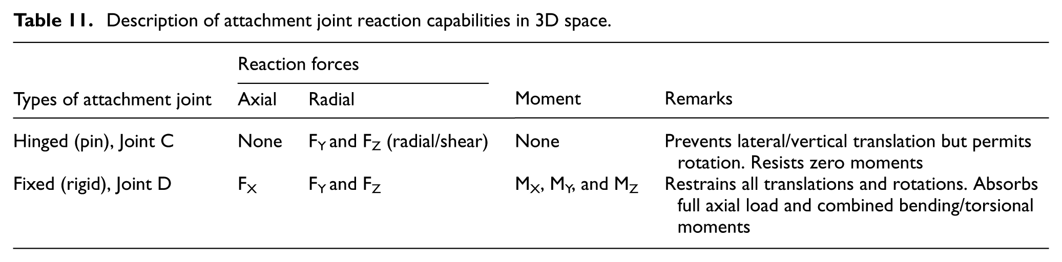
As established in Table 11, the hinged joint (Point C) acts as a specialized guide, allowing rotation relative to its primary axis without transmitting bending moments. It functions solely to transmit transverse shear forces, preventing lateral displacement of the mast. Conversely, the fixed root joint (Point D) restrains all relative degrees of freedom between the probe and the fuselage bulkhead, forcefully transmitting all axial loads, complex bending moments, and torsional reactions. A 3D numerical structural estimation of the refuelling probe under these specific hinged-fixed boundary conditions was executed to evaluate localized stress mapping. The numerical analysis perfectly corroborated the analytical findings: the maximum equivalent stresses occurred under the combined radial and ultimate axial compressive loading conditions at 225°.
Description of attachment joint reaction capabilities in 3D space.
While the analytical methods successfully established the macroscopic equilibrium and identified the critical load paths, the 3D numerical framework was essential for mapping localized stress concentrations (Kt) across the non-uniform cross-sections, complex bolt patterns, and mounting flanges. The integration of both methods confirms that the hinged-fixed idealization offers the optimal structural response for the retrofit design, successfully restraining extreme operational translation while preventing the catastrophic moment transfer that would occur in an overly stiff fixed-fixed configuration.
The one-dimensional numerical estimation of the refuelling probe, utilizing the validated hinged (Point C) and fixed (Point D) boundary conditions, was conducted to evaluate the distribution of resultant bending moments across various loading scenarios. As illustrated in Figure 10(a) to (c), the maximum bending moments occur under the combined radial and axial compressive loading condition at the 225° orientation. This numerical trend flawlessly corroborates the analytical results, confirming that the peak bending demand is concentrated at the fixed root (Point D). The comparative plots in Figure 10(d) to (f) demonstrate a high degree of correlation between the closed-form analytical solutions and the 1D finite element results. This direct overlay confirms the accuracy of the assumed load paths and boundary conditions, serving as the necessary verification baseline before proceeding to the localized 3D stress mapping of the attachment joints.

Numerical analysis results of the probe geometry under different support configurations: (a–c) hinged fixed support configuration and (d–f) fixed hinged support configuration.
Verification of analytical and numerical moment prediction
The analytical framework was numerically verified by comparing the closed-form solutions against the 1D Finite Element Model (FEM), demonstrating a high degree of correlation. This cross-verification ensures the mathematical integrity of the force and moment distributions under the established propped-cantilever boundary conditions. Figure 11 presents a quantitative comparison between the analytical and FEM-derived moments at the point C. The results were highly consistent, with minor deviations attributed to localize discretization and modelling assumptions. The specific error percentages for the reaction moments Mx, My, and Mz were 1.93%, 1.79%, and 4.43%, respectively. The cumulative average error of 2.72% indicates excellent conformity between the two methodologies, successfully establishing the verified baseline required for the subsequent 3D high-fidelity analysis.

Comparison of moments at point ‘C’ due to radial load (analytical model vs FEM model).
Structural analysis of attachment concepts and design optimization
Following the 1D verification, the three-dimensional structural integrity of the refuelling probe attachment joints was analysed using ANSYS. The assembly concepts were evaluated under peak axial tension, compression, and radial load cases. In the initial Concept 1 design, the structural interface relies primarily on the clamping force generated by bolt pretension. However, under ultimate axial compression and tension, the high longitudinal forces exceed the frictional resistance of the interface, leading to potential joint slippage. Furthermore, the introduction of radial tip loads imposes a significant twisting moment that compromises the stability of the clamped connection. To mitigate these risks, Concepts 2 and 3 incorporate integrated anti-rotation mechanisms and flanged interfaces. The introduction of the flange bolted joint in Concept 2 provides a positive mechanical stop against axial loads, effectively eliminating the risk of sliding. Concept 3 further enhances this by employing a double-shear joint configuration, which significantly improves the handling of complex twisting moments and ensures the probe maintains operational alignment under the 360° radial load envelope.
As summarized in Table 12, the iterative design process culminated in Concept 3, which achieved the highest Reserve Factor of 1.23 while reducing total system mass to 58.8 kg. This represents a significant improvement in structural efficiency, as the double-shear configuration successfully decouples the axial docking impacts from the induced torsional moments, providing a more rugged and reliable attachment interface compared to the initial clamped design.
Comparative inference on the iterative development of refuelling probe attachment concepts.

The structural response of the three attachment concepts under critical loading orientations (135°, 180°, and 225°) for the baseline configuration is illustrated in Figure 12(a) to (c). The numerical results demonstrate that Concept 3 achieves the superior structural response, characterized by significantly reduced von Mises stresses, the absence of critical shear concentrations in the fasteners, and minimal global deformation. These findings substantiate the mechanical stability of the double-shear configuration. Conversely, Concept 1 despite its superior mass efficiency exhibited the highest stress concentrations and deformation magnitudes, particularly under the 135° and 180° loading conditions, suggesting a heightened risk of structural yielding. While Concept 2 provided improved stress distribution relative to Concept 1 due to the integrated flange, its overall performance remained inferior to the optimized architecture of Concept 3.

Stress analysis for various refuelling attachment configurations in the considered: (a–c) base model and (d–f) iteration-1.
Subsequent evaluations of the Iteration 1 (geometric optimization) and Iteration 2 (material enhancement) configurations revealed consistent performance trends, as shown in Figures 12(d–f) and 13(a–c). For the baseline model, Concept 3 consistently maintained lower stress and deformation profiles than the alternative concepts. The geometric modifications introduced in Iteration 1 successfully reduced peak stresses and deformations across all concepts by smoothing stress gradients at the mast-bracket interface. In Iteration 2, which utilized alternative high-strength aerospace alloys, Concept 3 continued to exhibit the highest Reserve Factors (RF). Throughout both design iterations, Concept 2 demonstrated superior stress distribution compared to Concept 1. Ultimately, Concept 3 provided the most reliable structural response, establishing it as the optimal design for fixed refuelling attachments.
In Iteration 3, the geometric configurations and material selections for critical components were simultaneously optimized. This synergistic approach specifically tailored for the fixed refuelling attachments resulted in enhanced structural strength and geometric stability compared to the independent optimizations in Iterations 1 and 2. Due to the refined geometry and advanced material selection, Concept 3 exhibited peak performance, following established structural patterns. These results demonstrate that integrated geometry–material optimization significantly improves the robustness and design efficiency of the fixed refuelling attachment system. Figure 13(d) to (f) illustrates the critical consequences of these design principles at the 135°, 180°, and 225° loading orientations. Furthermore, Figure 14 provides a quantitative comparison of system mass versus peak deflection across all attachment configurations to illustrate the final structural efficiency gains.

Stress analysis for various refuelling attachment configurations in the considered: (a–c) iteration-2 and (d–f) iteration-3.

Comparison of Mass Vs deflection for various (a–d) iterative refueling probe attachment concepts.
Conclusions
This study establishes a verified and retrofit-compatible structural design methodology for fixed air-to-air refuelling (AAR) probes, specifically tailored for lightweight combat aircraft. Historically, research into the structural attachment joints of fixed AAR systems has been sparse in open literature, largely due to military sensitivity and the proprietary nature of aerospace certification data. This investigation addresses this critical research gap by proposing a unified framework that integrates CFD-based aerodynamic load estimation, analytical free-body characterization, and iterative 3D finite element optimization.
Key findings and contributions from this investigation are summarized as follows:
The research establishes a first-of-its-kind integrated framework for AAR probes. While prior studies have addressed aerodynamics (CFD) or flight dynamics in isolation, this study simultaneously resolves the multi-axial load transfer behaviour across bolted interfaces, providing a complete structural ‘pedigree’ from airflow to fastener stress.
Systematic benchmarking confirms that while aerodynamic and inertial flight loads (quantified at 4000 and 1475.5 N, respectively) are vital for fatigue and envelope verification, the primary structural sizing of the attachment joints is governed by the 13,350 N ultimate refuelling impact prescribed by MIL-A-8865B and STANAG-3447.
Comparative evaluation of three attachment concepts identifies Concept 3 utilizing a double shear, keyway integrated, and flange stabilized architecture as the superior design. This configuration effectively decouples axial and torsional load paths, achieving a Reserve Factor (RF) of 1.23 and eliminating the joint slip and stress concentrations observed in conventional clamped designs.
Through iterative geometry and material refinement, an optimal weight distribution was achieved, maintaining a high-strength overhung sub-assembly mass of 18.8 kg. This ensures structural resilience under peak operational stresses while facilitating retrofit integration with minimal fuselage modification.
The study utilized the Second Moment-Area Theorem to resolve the reactions of a statically indeterminate propped-cantilever system. These analytical results were numerically verified against 1D and 3D FEA models, demonstrating mathematical consistency and providing a deterministic basis for joint-level stress mapping.
The structural principles demonstrated including anti-rotation stabilization, deterministic load paths, and reserve factor based qualification are broadly applicable to other slender, cantilevered aerospace components such as sensor booms, pylon interfaces, and UAV payload mounts. By connecting classical structural mechanics with high-fidelity numerical verification, this research advances the state of the art in AAR integration and provides a certified baseline for future investigations into fatigue life, damage tolerance, and high-cycle dynamic response. Although this investigation was confined to analytical and numerical analyses due to confidentiality restrictions, the resulting stress magnitudes, deformation trends, and reserve factors align closely with published experimental data for comparable bolted aerospace joints. Future work will include physical sub scale testing of the attachment assembly to experimentally validate the computational framework.
Footnotes
Handling Editor: Aarthy Esakkiappan

Funding
The authors received no financial support for the research, authorship, and/or publication of this article.
Declaration of conflicting interests
The authors declared no potential conflicts of interest with respect to the research, authorship, and/or publication of this article.
Data availability statement
All presented data will be made available on reasonable request.*