
Abstract
Slender thin-walled members are main components of modern engineering structures, whose buckling behavior has been studied widely. In this article, thin-walled members with simply supported loaded edges can be discretized in the cross-section by semi-analytical finite strip technology. Then, the control equations of the strip elements will be rewritten as the transfer equations by transfer matrix method. This new method, named as semi-analytical finite strip transfer matrix method, expands the advantages of semi-analytical finite strip method and transfer matrix method. This method requires no global stiffness matrix, reduces the size of matrix, and improves the computational efficiency. Compared with finite element method’s results of three different cross-sections under axial force, the method is proved to be reliable and effective.
Introduction
Buckling analysis is the most important step during the design of slender elements which can be applied in different branches of engineering, including mechanical construction, marine applications, and civil architecture. 1 Thin-walled structure, a main kind of slender structure, is widely utilized to lighten engineering structures as well as save materials. 2
The buckling phenomenon is one of the chief failure models of thin-walled structure, which has been studied by experimental or mathematical means. 3 In the early works, the stability and vibration of thin flat-walled structure, acted by compression forces, have been analyzed by a matrix method. 4 It is based on energy rule that the elastic buckling modes of I-section beams has been studied. 5 Up to now, many methods have been used to analyze the buckling problems of thin-walled structure, such as finite difference and finite element methods (FEMs), 6 nonlinear FEM, 7 generalized beam theory,8,9 direct strength method, 10 semi-analytical finite strip and spline finite strip methods, 11 and constrained finite strip method (cFSM). 12 In addition, by introducing a computer procedure, the calculation of the stresses and failure models in thin-walled structural members has been presented. 13 And an experimental program investigating the column behavior of four sizes of square hollow sections has been introduced. 14
Although the FEM has been widely applied in the analysis of buckling behavior of thin-walled structures, the choices of the elements and the mesh sizes have significant influences on the results. 15 When calculating the buckling problems of structures which only have complex geometry shape in their cross-section, finite strip method (FSM) can be regarded as an efficient and powerful technology. And using the sub-parametric mapping concept, the arbitrary-shaped member can be discretized as many strip elements. 16 By introducing the spline finite strip method, the buckling stresses and natural frequencies of prismatic plate and shell structures have been predicted. 17 If a fictitious shear strain is adopted, a drilling rotation is introduced in the standard Mindlin–Reissner finite strip for the analysis of thin-walled sections. 18 Based on the concept of the semi-energy approach, the FSM can be proposed to analyze the buckling, 19 shear buckling, 20 and stability analysis of composite laminated plate and cylindrical shell structures. 21 The longitudinal harmonic series satisfying the boundary conditions at the longitudinal ends are generally employed in semi-analytical finite strip method (SAFSM). 22 The SAFSM based on the shallow shell theory is developed to the buckling analysis of prismatic structures which have curved corners. 23 And the SAFSM has been used in computer software (such as THIN-WALL 24 and CUFSM 25 ) to develop the signature curves 26 of the buckling stress versus buckling half-wavelength for thin-walled members. Furthermore, the cFSM innovated from SAFSM is developed and applied in the determination and classification of buckling modes. 27 By extending the applicability of the cFSM to the domain of general finite element analysis, the buckling modal identification of the thin-walled member has been demonstrated. 28
The classical transfer matrix method (TMM) has been developed as an effective tool for structural analysis, especially for chain connected system from topological perspective. 29 By combining the TMM and FEM, the finite element-transfer matrix method (FE-TMM) is developed to analyze the static and dynamic of structural problems. 30 And then a structural analysis method, named as boundary element-transfer matrix method (BE-TMM), is proposed for the vibration analysis of two-dimensional plate acted by uniform 31 and concentrated 32 loads. If the numerical integration is used, the nonlinear dynamics of structures, 33 the dynamics of multi-rigid-body system, 34 and multi-rigid-flexible-body system 35 can be simulated by TMM. And a new method, named as transfer matrix method of linear multibody system (MSTMM), is developed to study the hybrid multibody systems dynamics. 36 By combining FEM and discrete time transfer matrix method of multibody system (MS-DT-TMM), the dynamics of general planar flexible multibody systems including flexible bodies with irregular shape is studied. 37
Nowadays, the buckling analysis of the plate with built-in rectangular delamination has been implemented by strip distributed transfer function method. 38 And the TMM can be used to analyze the instability in unsymmetrical rotor-bearing systems 39 and tall unbraced frames. 40 The buckling analysis of rectangular thin plates via semi-analytical finite strip transfer matrix method (FSTMM), which is enlightened by above three references, has been developed. 41 In this article, FSTMM can be extended to analyze the buckling problems of thin-walled member with simply supported loaded edges. This article is organized as follows: in section “The Semi-analytical finite strip analysis,” the general theorem of the semi-analytical finite strip for buckling analysis of thin-walled member is shown. In section “Semi-analytical FSTMM for buckling analysis,” the FSTMM for buckling analysis is studied. In section “Examples and analysis,” some results calculated by FSTMM and FEM are given to validate the method. The conclusions are presented in section “Conclusion.”
The semi-analytical finite strip analysis
Degree of freedom and shape function
In the FSM, a thin-walled member as shown in Figure 1(a) can be discretized into many strips in longitudinal direction. Two left-handed coordinate systems are used: global and local. The global coordinate system is denoted as X-Y-Z, with the Y axis parallel to the longitudinal axis of the member. The local system is denoted as x-y-z, which is always associated with a strip and z axis is perpendicular to the strip as shown in Figure 1(b). We introduce a numbering system of finite strip model as shown in Figure 1(a). The total number of strips is s; therefore, the total number of nodal lines is s + 1 for open cross-section. Each nodal line i has two membrane degrees of freedom (DOFs)

Coordinate systems and displacements: (a) discretization and numbering of a member and (b) Degree of Freedom and loads of a strip.
The analytical trigonometric functions of the longitudinal coordinate that satisfy the simply supported boundary condition of the loaded edges can be used to represent the strip’s deformed configuration25,27
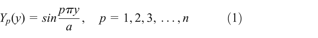
where p is the half-wave number, which also stands for certain half-wavelength along the longitudinal direction; y is the longitudinal coordinate in local coordinate system; and a is the length of the member.
The shape function for the membrane DOFs uses a linear function along transverse direction. And four cubic polynomials can be selected as the shape functions to depict the bending displacement of the strip along transverse direction. Then, the explicit expressions of u, v, and w can be given as follows


where subscripts i and j denote two nodal lines of one strip, and m is the maximum half-wave number employed in the analysis, which is a finite positive integer.
Fundamental stiffness matrix
The elastic stiffness matrix of FSM can be established similar to the deduction of FEM. If the plane stress assumptions and Kirchhoff plate theory may be employed, respectively, the total strain
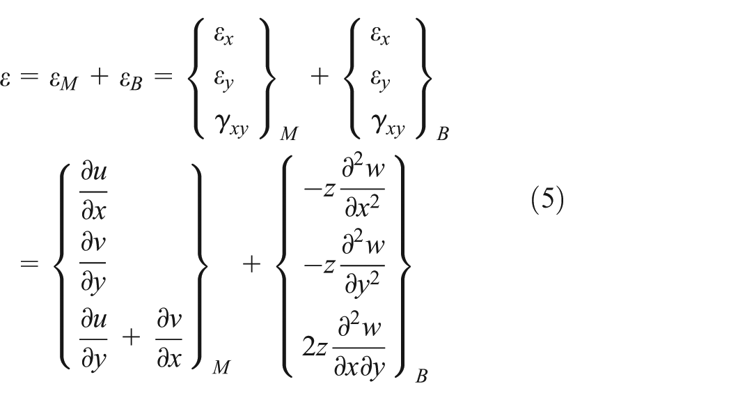
where u, v, and w are given in section “Degree of freedom and shape function.”
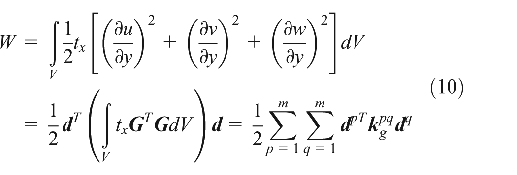
As to general linear elastic material, the elastic deformation energy can be expressed as

where
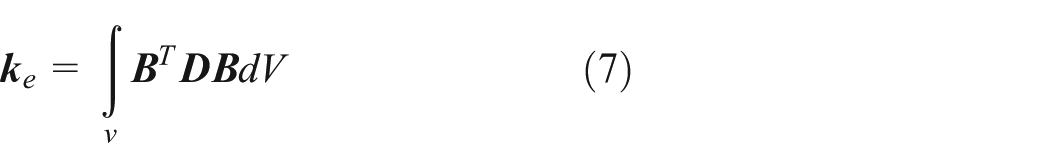
The
where
As shown in Figure 1(b), the strip is loaded with linearly varying edge tractions. The membrane compressive loads can be expressed as

where
where

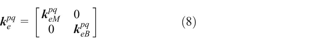
The
where
Semi-analytical FSTMM for buckling analysis
Control equations of strip element
In both FE-TMM and BE-TMM, the transfer equations of the given sub-structure can be deduced by the control equations of this sub-structure which consider the interaction forces between this sub-structure and other structures. As to the proposed FSTMM, the strip element can be regarded as the sub-structure.
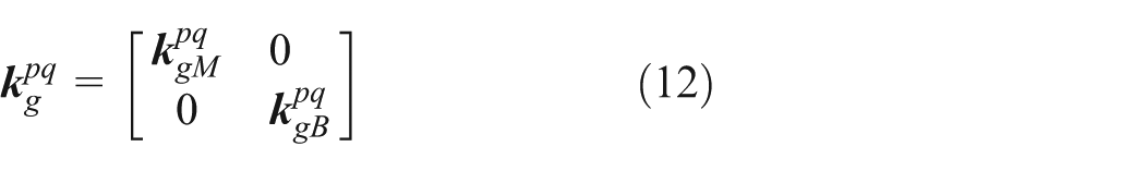
If the orthogonal conditions about
where

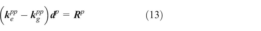
where

where
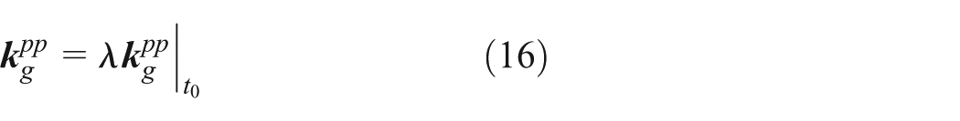
By substituting equation (16) into equation (13), the control equations of the buckling strip can be rewritten as follows
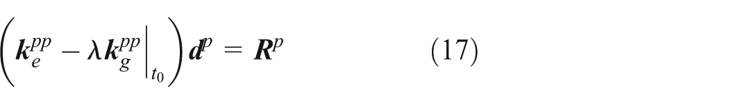
To simplify the equation, the coefficient matrix of the nodal line displacement vector
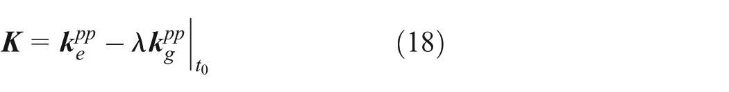
where both coefficient matrices
State vector, transfer equations, and transfer matrix
During the deduction of transfer matrix of the system, the state vector of the nodal line is an important concept that includes two parts: one part describes the generalized displacement of the nodal line, and the other part gives the generalized internal forces acting on the nodal line by other members in the system. For example, the state vector of the nodal line l can be defined as
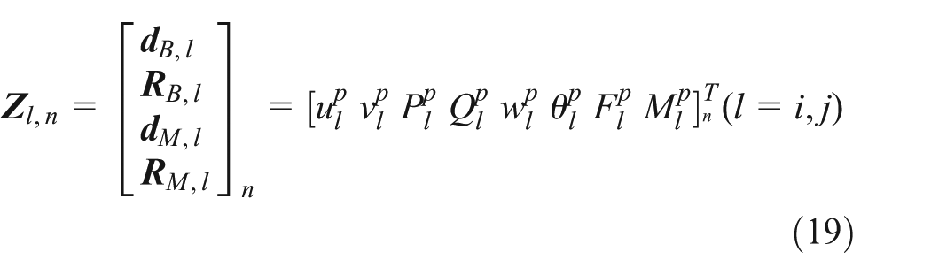
where the first subscript l denotes the number of the nodal line, the second subscript n denotes the number of the strip,
Using the block forms of equation (19), the control equations (17) can be rewritten as the form of the transfer equations of this strip, namely

where the transfer matrix of the strip n is

where the subscript n denotes the number of the strip,

According to the condition of displacement continuum and the law of action and reaction, the transformation of the state vector from strip n to strip
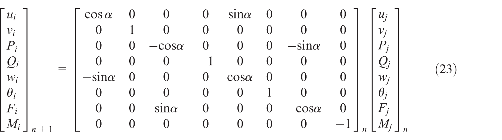
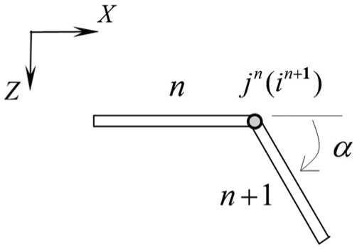
Transformation at the nodal line.
This can be simplified as the following form

where

Using the same procedure used in classical TMM, the overall system transfer equation and the overall transfer matrix


where the subscript s is the total number of strips.
Examples and analysis
Illustrations of open cross-section members
For the buckling analysis of open cross-section members with simply-simply (SS) supported boundary condition of loaded edges in this dissertation, the two unloaded edges are free, which can be expressed by SSff. Here, the capital letters and lowercase letters denote the loaded edges and unloaded edges correspondingly.
Take the boundary condition SSff into analysis, the total transfer equations can be deduced as follows
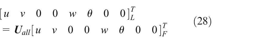
where subscripts F and L denote the first and last nodal lines of the member and
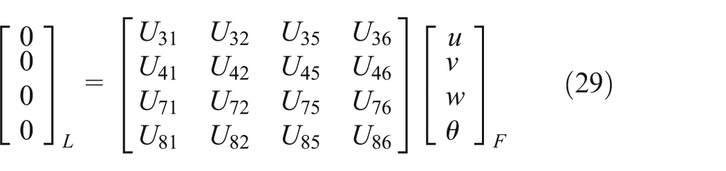
where
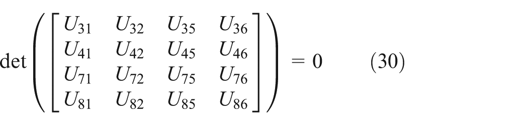
Above equation is the characteristic equation of the buckling of open cross-section member by the FSTMM, which can be used to calculate the buckling coefficients. If we combine equation (29) with equation (25), the buckling mode can be obtained. In order to demonstrate the method, two typical examples are considered: a C-section member and a Z-section member.
Illustrations of C cross-section member
The dimensions of the C-section member are presented in Figure 3(a). The section height is 200 mm, the flange width is 80 mm, the flange lip length is 20 mm, the plate thickness is 2 mm, and the initial axial force

Cross-section: (a) C-section member and (b) its FSM mesh.
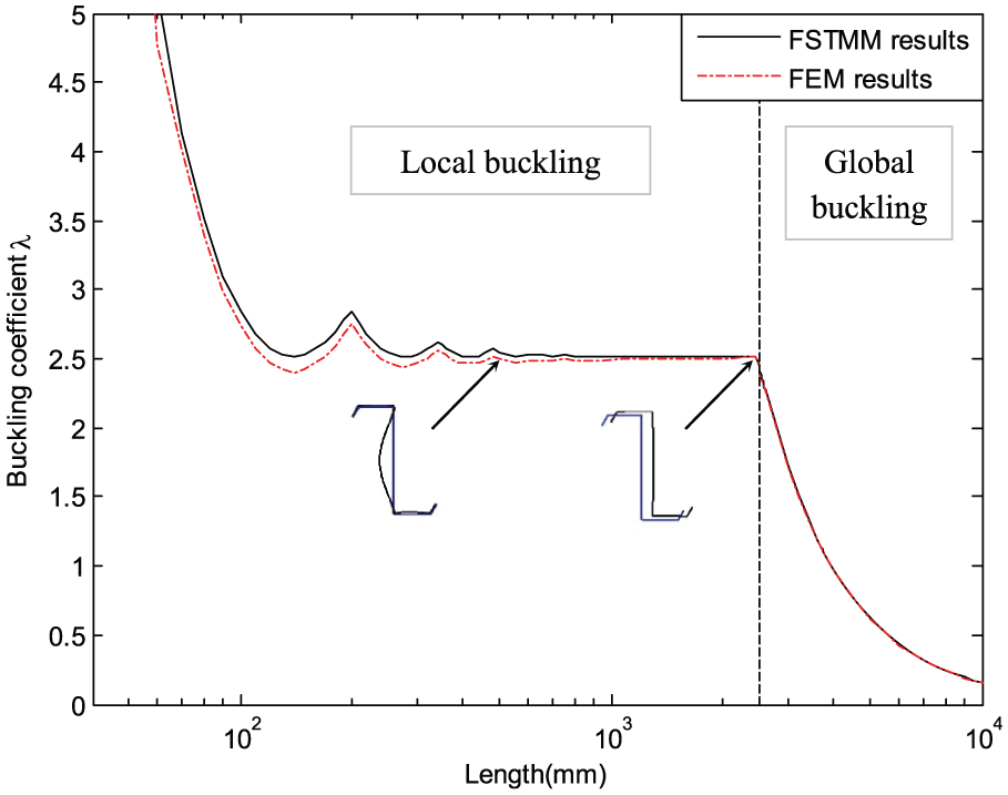
Along the loaded edge, the member is divided into 11 strips, as shown in Figure 3(b). Figure 4 shows the classic signature curve, which can be used to determine and classify the buckling modes, by both FSTMM and conventional FSM for the section in axial compression.
14
We notice that two curves have good agreements. The relationship schema between buckling coefficient

Classic signature curves of FSTMM and FSM of C-section member.

Buckling curves of C-section member.
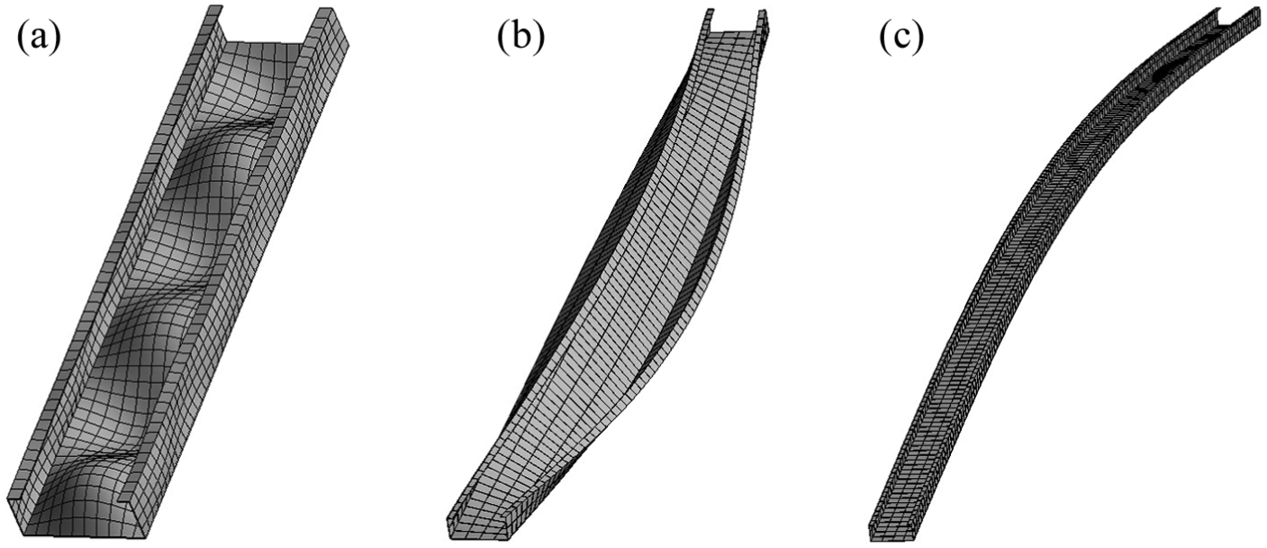
Buckling shapes of C-section member: (a) a = 1000 mm, local buckling; (b) a = 3750 mm, global torsion and(c) a = 8000 mm, global bending.
Illustrations of Z cross-section member
Another example to validate the theory is a Z-section member. The dimensions are presented in Figure 7(a), the section height is 180 mm, the flange width is 60 mm, the flange lip length is 20 mm, and the plate thickness is 2 mm. The member is divided into 10 strips along the loaded edge, as shown in Figure 7(b). In this section, the numerical results concerning the buckling behavior of the Z-section member subjected to axial compression and axial bending are presented.

Cross-section : (a) Z-section member and (b) its FSM mesh.
Figure 8 shows the relation between the buckling coefficient
Buckling curves of Z-section member in axial compression.

Buckling shapes of Z-section member in axial compression: (a) a = 500 mm, local buckling; (b) a = 2500 mm, global buckling.
For the member under Z-Z axial bending moment
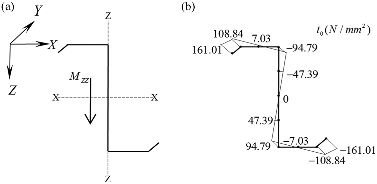
Z-section member in Z-Z axial bending: (a) direction of bending moment and (b) stress distributions.

Buckling curves of Z-section member in Z-Z axial bending.
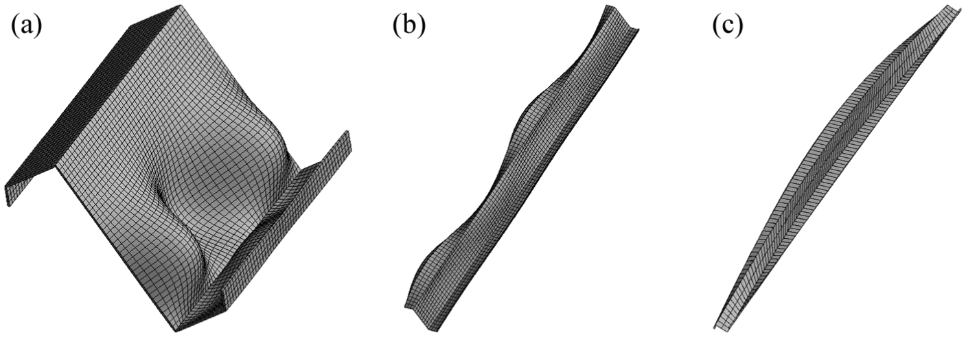
Buckling shapes of Z-section member in Z-Z axial bending: (a) a = 250 mm, local buckling; (b) a = 2000 mm, distortional buckling; and (c) a = 10,000 mm, global buckling.
Illustrations of closed cross-section member
In order to demonstrate the efficiency of FSTMM to analyze closed cross-section, a rectangular hollow section is studied, as shown in Figure 13. Different from open cross-section members illustrated in section “Illustrations of open cross-section members,” there is no unloaded edge in a closed cross-section member. In other words, the first and last nodal lines are the same nodal line in the analysis. To satisfy the closed forms, equation (28) can be modified as follows
where the subscript F denotes the first nodal line of the member,

where

The geometrical properties of the member (Figure 13(a)) are as follows: the height is 100 mm, the width is 60 mm, the plate thickness is 1.5 mm, and the initial axial force

Cross-section: (a) rectangular hollow section member and (b) its FSM mesh.

Buckling curves of rectangular hollow section member.

Buckling shapes of rectangular hollow section member: (a) a = 800 mm, local buckling; (b) a = 2550 mm, global buckling.
Precision analysis
As a general rule, the computational precision can be improved by increasing the number of elements. By comparing the results calculated from FEM’s shell model and FSTMM of buckling problems of C-section member, the influence of the strip number to the computational precision can be analyzed. The buckling behaviors can be obtained by the FSTMM with the strip numbers 5, 8, and 11, respectively, shown in Figure 16(a)–(c). Figure 16(d) shows the FEM’s shell model which is used for comparative analysis.
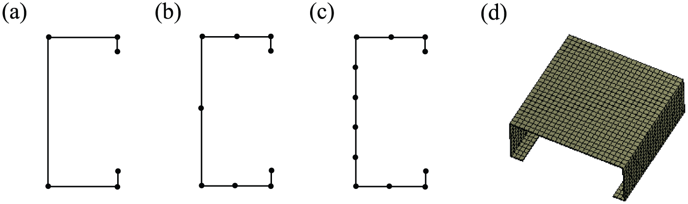
FSTMM and FEM meshes: (a) five strips; (b) eight strips; (c) eleven strips and (d) FEM mesh.
Figure 17 compares the influence of the strip number to the computational precision in FSTMM. When the number of strips n = 8 in FSTMM is selected, the computational results have good agreement with the FEM’s results. It can be confirmed that the proposed FSTMM has good efficiency for the buckling analysis of thin-walled members under the boundary condition of simply supported loaded edges.

Comparison between different models.
Conclusion
In this article, the semi-analytical FSTMM is proposed to analyze the buckling problems of open and closed cross-section members under the boundary condition of simply supported loaded edges. In order to validate the method, the examples of the open and closed cross-section members can be designed and analyzed by the different methods in section “Examples and analysis.”
It may be found that the method holds several highlights: (1) demands no global stiffness matrix and reduces the size of matrix in the system analysis by combining the semi-analytical finite strip and the transfer matrix technologies, (2) both open and closed cross-sections can be calculated by the method in the same way, and (3) the method has the advantages of determination and classification of buckling modes same as FSM.
Footnotes
Academic Editor: Chuanzeng Zhang
Declaration of conflicting interests
The author(s) declared no potential conflicts of interest with respect to the research, authorship, and/or publication of this article.
Funding
The author(s) disclosed receipt of the following financial support for the research, authorship, and/or publication of this article: The research is financed by National Key Science Foundation Program (51624001) and Natural Science Foundation of Jiangsu Province, China (BK20130911).