
Abstract
The design of a compact Gough-Stewart platform for physical hippotherapy is presented using pneumatic muscles and a central pre-stressed spring to achieve bidirectional motion. The use of the Gough-Stewart platform is advantageous as it drastically increases the workspace accessible by a therapist. The system is designed to reproduce walk, trot, and gallop trajectories derived from motion capture data. The model-based geometry optimization reduces actuator forces under workspace and collision constraints. The control of the pneumatic muscles combines inverse-dynamics and PID loops with a neural network feedforward. The latter compensates for the nonlinear spring characteristics. Experiments show that the system can generate the desired motion profiles, is robustness regarding variable load, and thus suitable for therapeutic use.
Keywords
Introduction
Horse riding as physical training, referred to as hippotherapy, has shown to be a means for improving health conditions even in case of partial paralysis. It was shown that hippotherapy has a positive effect on gait training for post-stroke individuals. 1 To make such therapies accessible for a wider spectrum of users, a robotic hippotherapy system was proposed. 2 This system consists of a 6 DOF serial robot with a riding saddle attached at the end-effector. While this is a major step toward a systematic approach to clinical hippotherapy, the system is heavy, difficult to transport and install in buildings like hospitals, and has a relatively high energy consumption. Moreover, since the saddle is suspended at a heavy-duty serial robot a significant part of the space is covered and cannot be used by the therapist. Ideally, the therapist should be able to move around the patient, which is not possible when using serial robots. In this paper, a tailored Gough-Stewart Platform (GSP) is proposed that overcomes these shortcomings. Such parallel kinematics machines (PKM) are well-established as agile manipulators, motion simulators, machine tools, etc. After three decades of research, their kinematics and dynamics is well understood.3,4 Besides hydraulic actuation, GSPs equipped with electric spindle or linear drives are frequently used to achieve highly dynamic yet precise motions. 5 The GSP presented in the following is actuated by pneumatic muscles. These actuators are special in that they can only generate pulling forces and achieving high precision is challenging. This topic has been addressed in the past. The use of pneumatic muscles is a classical approach in particular for actuation of assistive devices and GSP.6,7 A detailed dynamics modeling of pneumatic muscles that can be used for model based control was reported. 8 To generate bidirectional motions, the design of hybrid actuators consisting of one muscle and a spring was presented. 9 Instead of using one spring per actuator to counteract, a 6 DOF Hexapod PKM was presented, 10 where 12 with pneumatic muscles are used in an agonist antagonist setup. The design optimization of a pneumatically driven GSP with focus on disturbance forces and workspace maximization was reported. 11 With focus on uncertainties, a flatness based control of pneumatically driven carriage 12 was presented.
For the intended hippotherapy application the generation of high accelerations is important while the precision is less important. In this paper the design of a GSP for realistic hippotherapy driven by pneumatic muscles is presented. To generate spatial bidirectional motion, i.e. generate push and pull forces an antagonistic spring is introduced. To account for the overall nonlinear characteristic, thus to improve the position control, a neural network is used. A design optimization is pursued in order to minimizing actuator forces and limit the space occupied by actuated struts and at the same time optimize the available workspace for saddle and rider. The actual trajectories resembling horse rides, in the form needed by the hippotherapy, is generated from motion capture data of real horse rides.13,14
The main key innovations of this paper are as follows: • Configuration innovation: Achieving 6-DOF bidirectional motion using a single set of six pneumatic muscles combined with a central pre-stressed spring. • Multi-objective optimization: Geometric and attachment point optimization specifically tailored for dynamic equestrian gaits. • Hierarchical control scheme: A novel integration of Neural Networks, inverse dynamics, and PID control.
Horse riding trajectories
Hippotherapy is based on measurements from moving horses. For that, markers are put on the horses and the position of these are recorded by optical methods.
13
A special algorithm for marker selection during horse motion for different motion profiles is presented. The different motion profiles are walk, trot, and gallop. Figure 1 shows a sketch of a horse with markers on the horseback. The trajectories are described as Horse with markers.


Since the motion is periodic, the trajectories q are parametrized as Fourier series

Goal of the optimization is to identify the motion of the model from marker data of a specific gait measurement. The position
I
m
i
of a specific marker i on the horseback is determined by Exemplary trajectories for position, orientation angles, velocities, accelerations for one cycle of trot motion.


Design optimization of new simulator
An evaluation of the horse trajectories in Section Horse Trajectories delivers that the trot is the most dynamic motion that act on the saddle and rider. To design a simulator, this motion q is used for optimizing the geometrical layout w.r.t. kinematics and dynamics. In this context, a parallel kinematic machine has advantages over serial robots. Since all 6 degrees of freedom are necessary to fully rebuild the motion, a Gough-Stewart platform (GSP), 3 is best suited.
Kinematic model
For a description of the horse motion, the minimal coordinates q (position r
H
, orientation ph
H
, R
IH
) are used. For the design optimization, the inverse kinematics model, that is calculating the length of the legs l
i
, i = 1..6 as function of the position and orientation q, is necessary. Note, the lengths l are the actuator lengths of the GSP simulator are different to the real horse. Based on Figure 3 the inverse kinematics for one leg is Topology of a GSP leg.


Design vectors I c i on the base and H d i on the saddle are constant in their respective frame and give space for design optimization. They serve as attachment points for linear actuators.
A forward kinematics model is necessary to evaluate the position and orientation of the moving plate based on the lengths of every leg and is used especially in the Experimental Results section. An iterative, numerical method is chosen that is based on constraints equations using the inverse kinematics

Dynamic model
The dynamics model is necessary, since the horse motions are very dynamic with high accelerations. Using a standard method like Projection Equation
18
gives the equations of motion (EOM) in the form

For optimization and control purposes the inverse dynamics model is necessary. Rewriting Eq. 9 gives the actuator forces

based on the dynamic model and a prescribed motion
Optimization
The goal for the optimization is to find a design for which the high accelerations and actuator forces of the trot motion of the horse is possible. The mounting points c
i
, d
i
serve as design parameters and are therefore the optimization variables x. This leads to the formulation

This optimization problem is solved in Matlab using the fmincon function with sqp optimization. Convergence is achieved within a few iterations.
In Figure 4 the actuator forces for the optimized solution (solid lines) versus the initial design (dashed lines) can be seen. The forces can significantly be reduced from about 10 kN to a maximum of 5 kN. Such actuators can be found on the market. Optimized (solid) and initial (dashed) actuator forces for the 6 linear drives (muscles).
Figure 5 shows a top view of the mounting points for the base (l) and the moving plate (r). Exemplary vectors c3 and d3 for the initial choice and the optimized mounting points 3 are sketched, see also Figure 3. Initial vs. optimized mounting points (top view), (l) base plate, (r) moving plate.
A rendering of the optimized riding simulator can be seen in Figure 6. The linear actuators fit well into the design and a collision for the different motion profiles is avoided due to the optimal design. Rendering of optimized simulator.
Realization
Section Design Optimization presents the design and optimization of a riding simulator that is capable of performing all horse motion profiles (walk, trot, gallop) in original speed. However, for hippotherapy only slow motions in the walk mode can be used for patients. The walk profile leads to best therapy successes since it is quite similar to a human gait pattern regarding the hip movement. Slow motions are necessary to not further insure the patients and to give them a comfortable feeling during therapy. Therefore the trajectories are tested on an already built GSP that is available at the Institute of Robotics at the Johannes Kepler University Linz. The design optimization for this GSP can be found in literature.
11
In this publication the goal was to maximize the working space and disturbance forces that act on the center of the moving platform. Figure 7 shows a photo of the realized simulator. The system is driven by pneumatic muscles. Compressed air is putted into the muscle that contracts itself and delivers forces. These muscles are only able to pull on the moving platform. Therefore, a pre-stressed spring from a standard passenger car is located in the middle of the system to deliver all the pulling forces and torques. Basics about the setup are reported.
17
Photo of used Gough-Stewart Platform.
For the therapy it is very important to start with very slow velocities and speed up for higher trained patients. Therefore a time scaling with factor ξ = 0..1 is used. Zero means that the simulator is in standstill, while 1 means 100 % of the original horse velocity. The horse trajectories change due to time scaling to.\beginAlign


Setup
Mechanical setup
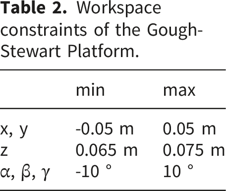
A schematics of the simulator without saddle can be seen in Figure 8. It is designed as 6UTS-mechanism. The main dimensions can be found in Table 1 while Table 2 shows the corresponding working range for all directions. Schematics of the Gough-Stewart platform. Main dimensions of the Gough-Stewart Platform. Workspace constraints of the Gough-Stewart Platform.

The 6 pneumatic muscles act as linear actuators and pull on the moving platform with forces F
i
, i = 1..6. The muscles are Festo DMSP40
19
with a nominal length of l0 = 0.38 m. The detailed dynamic behavior is complicated and described by characteristic lines in Figure 9. Each muscle has a maximum pressure of 6 bar and delivers up to 6 kN. The force depends on the pressure and the stroke h in % Characteristic lines of a pneumatic Festo muscle DMSP40.

The characteristics of the muscle in Figure 9 can be approximated by
8

The functions a(h) and b(h) are polynomials of order three and six, respectively. This model preserves the basic property that the force is an affine function in the relative muscle pressure p, which is important for many control algorithms. Due to the pre-stressed spring, the nonlinear terms g in the equations of motion Eq. 9 have to be expanded by these forces/torques g
k
(q).The spring acts in all directions and can not be adequately be approximated by linear models with a stiffness matrix K by g
k
= Kq. Such an approximation lacks in control performance.
17
Additionally, such springs do have a specific behavior in extreme positions as can be seen in Figure 10. Such a bulging behavior can not be modeled by a linear spring. Therefore, a neuronal network is used for an improved control performance, see Section Neuronal Network Feed Forward Control for details. Gough-Stewart Platform with bulged spiral spring.
Electrical and pneumatical setup
The electrical and pneumatical setup can be seen in Figure 11, while the main electric and pneumatic components can be found in Table 3. Electric and pneumatic scheme. Main electric and pneumatic components.

The system is controlled by a human instructor with a standard PC (Control PC) that is connected to the Automation PC (APC) via TCP protocol. The APC is a X20CP1585 computer from B&R and serves as realtime control system. The cycle time of the realtime system is 4 ms. All control algorithms including the neural net are evaluated within this time. Inputs for the realtime system are the measured lengths l i (linear potentiometer) as well as the measured pressure p i of every muscle. The control algorithm calculates the corresponding control signals u i for the pneumatic valves. The ith actuator unit consists of a muscle, a pressure sensor and a linear position sensor.
The pneumatic system is supplied by a compressor delivering air at a pressure of 6 bar. Due to high and fast air volume demand, an air tank with a capacity of 50 liters is positioned near the pneumatic valves. The air tank delivers the air volume flow (Q) for every valve as Q i . The controlled Qc,i as output of the pneumatic valve supports the muscles.
Neuronal network feed forward control
As shown in Figure 10, the characteristic of the spiral spring is highly nonlinear. This means that a linear approximation of the stiffness forces, i.e. g k (q) ≈ K q is insufficient. Instead, the idea is to use an artificial neural network due to its suitability for universal function approximation. Details for this approach can be found in literature, 20 where the NN is used to improve the control performance for an excavator simulator. In detail, the neural network (NN) should approximate g k (q) + g G (q) of (9), i.e. the superposition of the stiffness g k (q)- and gravity forces g G (q). Ideally, the trained NN delivers for a desired robot pose with muscle lengths l1…l6 the required pressures as output. Hence, for the feedforward control via neural network, i.e. p ff = p NN , only the desired poses are considered. The system and trajectory dynamics are completely neglected, since only a static behavior is trained.
Data acquisition
As generally known, a neural network (NN) requires a lot of data for training. Therefore, the position range of the six pneumatic muscles of the GSP is uniformly discretized with five positions per actuator leading to 56 = 15625 GSP poses.
For the discretization, the minimal and maximal considered muscle lengths l1…l6 are 485 mm and 535 m, respectively. For each of the 15625 poses, a standard PI controller with high integral gain is used to control the muscle lengths to the discretized poses. After a settling time, the current muscle position as well as the corresponding controller pressures p PI are measured and stored in a database.
Neural network structure and parameters
The recorded data at the different discretization poses should be approximated by an NN. Figure 12 shows a fully connected feedforward neural network (FNN) with three hidden layers with respective hidden neurons N1, N2 and N3 as well as an output layer with 6 neurons. As can be seen, the inputs of the NN are the desired lengths of the muscles l
d
, while the respective feed forward pressures p
ff
are the outputs. Neural network with three hidden layers.
All hidden layers use SELU as activation function, whereas the output layer considers just linear activation. The usage of SELU as activation function can lead to so-called self-normalizing networks, which avoid the problems of vanishing and exploding gradient. 21
One requirement of a self-normalizing NN is that the distribution of the input data must have zero mean and unit variance. So the desired muscle lengths, which represent the input data of the GSP NN, are correspondingly normalized or rather mapped. Such normalization is useful because it guarantees the equal importance of all inputs and it also might improve the convergence speed. 22
Figure 14 shows the presented control strategy, using a neural network for feedforward control p
ff
. Control concept.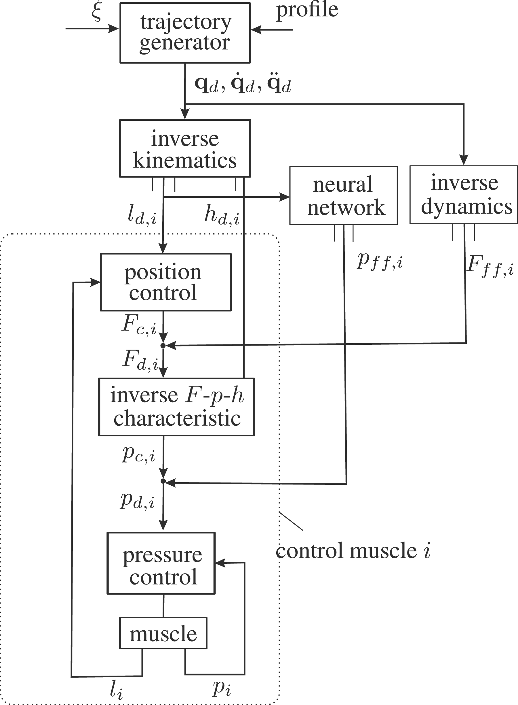
Training
The networks are implemented with the machine learning framework PyTorch 23 in Python. All NNs are trained with single batches using the stochastic gradient descent (SGD) optimizer, which works well for the SELU activation function 21 and dropout is deactivated.
Cross validation results on training data of tested NNs.

The neural network with hidden neurons (16,32,48) leads to the lowest loss. Considering these parameters, we train a new NN with corresponding input normalization using the whole training data (14063) to get the finally trained network. It should be noted, that a higher number of hidden neurons or layers might lead to even better results. However, such networks were not considered due to limited time and computational power for the NN evaluation directly at the B&R CPU. 25
NN validation. The performance of the finally trained network is checked against the test data with 1562 poses (novel data) and leads to a loss of 0.0023 compared to 1.2451 before training. Figure 13 exemplary shows every tenth value of the estimated pressures of the third axis. It can be seen that the pressures of the NN (p
ff
) correspond very well to the PI (p
PI
) values. The other axes are of similar quality. Comparison of PI control pressures p
PI
and recalculated pressures p
ff
from the NN for verification poses (axis 3).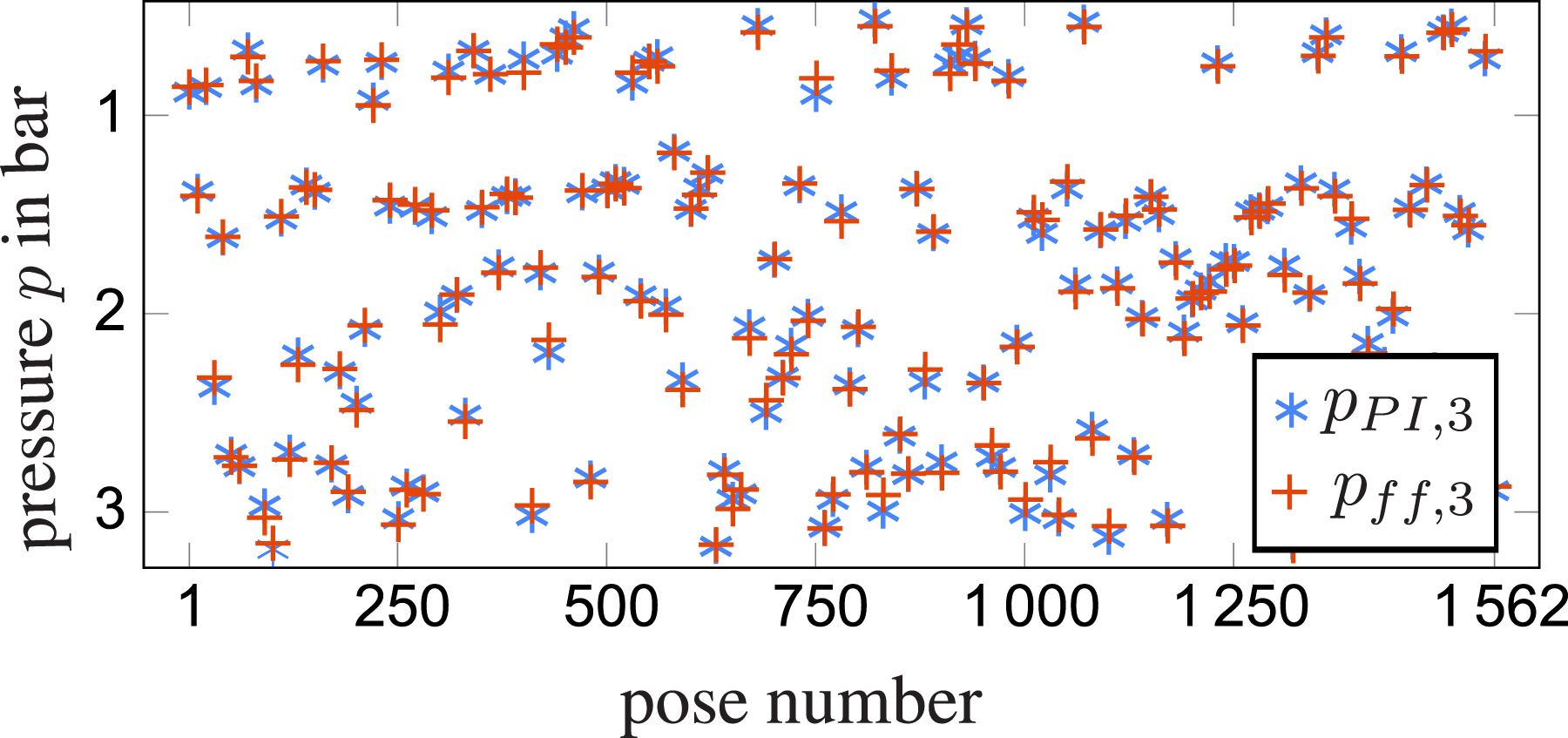
Control
For a high performance trajectory tracking control, the concept in Figure 14 is designed. The trajectory generator with time scaling factor ξ and a chosen horse motion profile (walk, trot, gallop) delivers the desired TCP trajectories 
It has to be noted, that the inverse dynamics model is calculated without the spring- and gravity forces since they are included by the neural network as can again be seen in Figure 14. The requested muscle force from the PID position controller and the feed forward forces Eq. 17 are superposed and transformed with the inverse muscle characteristics Eq. 16 and the desired stroke h d (Eq. 15) to desired control values for the pressure p c . These pressures are supported by feed forward pressures from the neural network p ff that account for gravity and the spring characteristic leading to the desired pressures for every muscle p d . These pressures are again controlled by an underlain PID pressure controller using the measurements p i .
Experimental results
Single Muscle Test: Exemplary, a comparison of desired muscle length ld,3 and measured length l3 for the third leg is shown in Figure 15. The remaining muscles behave similar. The top plot shows the trajectory tracking without the neural network feed forward control, while the bottom one shows the behavior with NN feed forward control. The control performance is significantly improved. The desired values for the muscle lengths are in this case high dynamical trapezoidal acceleration profiles to be able to better compare the control behavior. In this experiment, just one muscle is actuated while the remaining ones are not used. Therefore, the amount of needed air is sufficient and the air tank is able to provide the appropriate air volume flow. Trajectory tracking, top: trajectory control without neural network feed forward, bottom: trajectory control with neural network feed forward Trajectory
Trajectory Test Control - slow motion: The first test case for a horse trajectory with the focus on hippotherapy is the walk profile with 10 % of the original horse speed, i.e. ξ = 0.1. Therefore one period of the trajectory is about 18 s which is a quite slow motion. The corresponding plots are shown in Figure 16. To not overload the figures, for all remaining evaluation plots, only the pressures and lengths of legs 1 and 2 are shown. The two main motions in task space are the forward position x and the pitch angle β. For simplicity only these are plotted. For the measured values of the world coordinates, the measured lengths of the legs are used in a forward kinematics algorithm, leading to measured q. The top plot of Figure 16 shows a perfect following of the pressure values. Also the muscle lengths and the world coordinates show a good trajectory tracking. Walk motion profile for 10 % of original speed; top: pressure 1,2; middle: length 1,2; world coordinates x, β
Trajectory Test Control - fast motion: Although not relevant for therapy purposes, the same experiment is also performed at a higher speed of 50 % percent of the original speed. The results for this case are shown in Figure 17. One can see that there are small deviations in all three plots between desired and measured values. The main reason for this is that the required air volume for the muscle control can not be delivered by the tank without pressure losses. However when looking at the bottom plot in the figure it can be seen, that the main deviation is a time delay between desired and measured values. This time delay is about 0.05 s. Such deviations are for a therapy of minor importance. Walk motion profile for 50 % of original speed; top: pressure 1,2; middle: length 1,2; world coordinate x, β
For a last experiment, the influence of an external load, namely a patient, should be considered. Therefore, a person with a weight of 80 kg is putted onto the seat and tested with the fast trajectory. The results on this experiment can be seen in Figure 18. Comparing these results to the results in Figure 17 one can hardly see any difference. This indicates that the system is very robust w.r.t. External loads. This behavior is also very important for therapy purposes since the weight of the patient should not influence the system. Walk motion profile for 50 % of original speed with 80 kg external load; top: pressure 1,2; middle: length 1,2; world coordinates x, β
A video of the different motion profiles can be seen in the Youtube video https://www.youtube.com/watch?v=isgmkM9a0X8.
Control performance comparison.

Conclusion
A physical hippotherapy simulator was realized using a compact GSP actuated with pneumatic muscles along with a central pre-stressed spring. The design was optimized to maximize the accessible workspace and to reduce actuator forces. The motion trajectories are generated from real horse motions recorded with motion capture system. The platform position and the pressure of the fluidic actuators is regulated with an augmented PID controller incorporating model-based inverse dynamics and a neural-network feedforward that compensates the nonlinear spring behavior. The experimental evaluations show accurate trajectory tracking for slow walk motions, and acceptable performance at higher speeds with minor time delay due to air supply limits. It also shows robustness to a large payload range.
Future improvements may focus on improving the data-driven compensation to allow for larger operating ranges. From an application perspective, future work will address user experience through virtual reality integration.
Footnotes
Acknowledgements
This work has been supported by the “LCM - K2 Center for Symbiotic Mechatronics” within the framework of the Austrian COMET-K2 program.
Funding
The authors received no financial support for the research, authorship, and/or publication of this article.
Declaration of conflicting interests
The authors declared no potential conflicts of interest with respect to the research, authorship, and/or publication of this article.