
Abstract
This study presents a legged mobile robot based on a regular polyhedral structure that achieves a point-symmetric body configuration. The proposed framework enables dynamic allocation of manipulator roles based on a single reference vector (e.g., gravity), allowing consistent functionality across different body orientations without posture-specific control. The approach was validated through simulations on three polyhedral structures (octahedral, dodecahedral, and icosahedral) and hardware experiments using an octahedral robot. Experimental results demonstrate that the robot can perform grasping and crouching behaviors in all six stable orientations, while locomotion is achieved in two orientations under the current actuator constraints, with an average locomotion speed of 0.092m/s across 10 independent trials. In addition, stable posture recovery was confirmed across 10 independent fall-recovery trials with an average recovery time of 2.26s. The results further showed that the same posture representation and role assignment algorithm could be consistently applied across different polyhedral geometries without modification of the control structure. These findings indicate that point-symmetric design provides a viable framework for achieving orientation-independent operation while maintaining a minimal and generalized control structure.
Introduction
Robotic body structures have traditionally been designed with a strong emphasis on task-specific functionality. As a result, many systems adopt bilateral or fore–aft symmetry, reflecting both biological inspiration and engineering efficiency in achieving specialized behaviors such as locomotion or manipulation. While such designs are effective for targeted tasks, they implicitly introduce asymmetries in how functionality is distributed across the body, often leading to orientation-dependent behavior. In practice, this results in systems that require additional mechanisms or control strategies to handle changes in posture, such as recovery from falls. 1
In this study, we take a different perspective by considering geometric symmetry as a primary design principle rather than a byproduct of functional requirements. By focusing on how symmetry structures the relationship between body configuration and function, robotic systems can be designed to exhibit more uniform behavior across different orientations.
Prior studies have explored symmetry in several contexts. A radially symmetric tripod robot structure was proposed to equalize the functional roles of individual legs, thereby simplifying gait generation and enabling high-speed dynamic locomotion. 2 In automatic robot design, Symmetry-Aware Robot Design (SARD 3 ) has been introduced as a framework that utilizes group theory and subgroup structures to reduce the search space of robot morphologies. By incorporating symmetry into the structure of the design space, the method improves the efficiency of learning and optimization. Morphological symmetry has also been investigated as a geometric prior for robot dynamics and control, 4 where symmetry representations were shown to improve modeling accuracy and learning efficiency.
However, these studies mainly employed symmetry to improve existing functions such as locomotion generation, optimization efficiency, or learning performance, rather than investigating how symmetry itself can define and organize robotic functionality at the body-design level.
To further examine this perspective, we consider robotic morphologies in terms of both symmetry and degrees of freedom (DOF). Figure 1 presents a conceptual organization of representative robotic systems along these two axes, informed by prior surveys and representative examples in the literature.5–25 This comparison suggests that functionality is not solely determined by the number of actuated degrees of freedom, but also by how those degrees of freedom are arranged within a symmetric structure. In particular, for comparable levels of DOF, systems with higher geometric symmetry tend to exhibit more uniform and versatile functional capabilities, whereas less symmetric systems are often optimized for specific tasks. In other words, symmetry provides an additional axis for understanding and designing robotic capabilities. Conceptual illustration of the relationship between DOF and symmetry.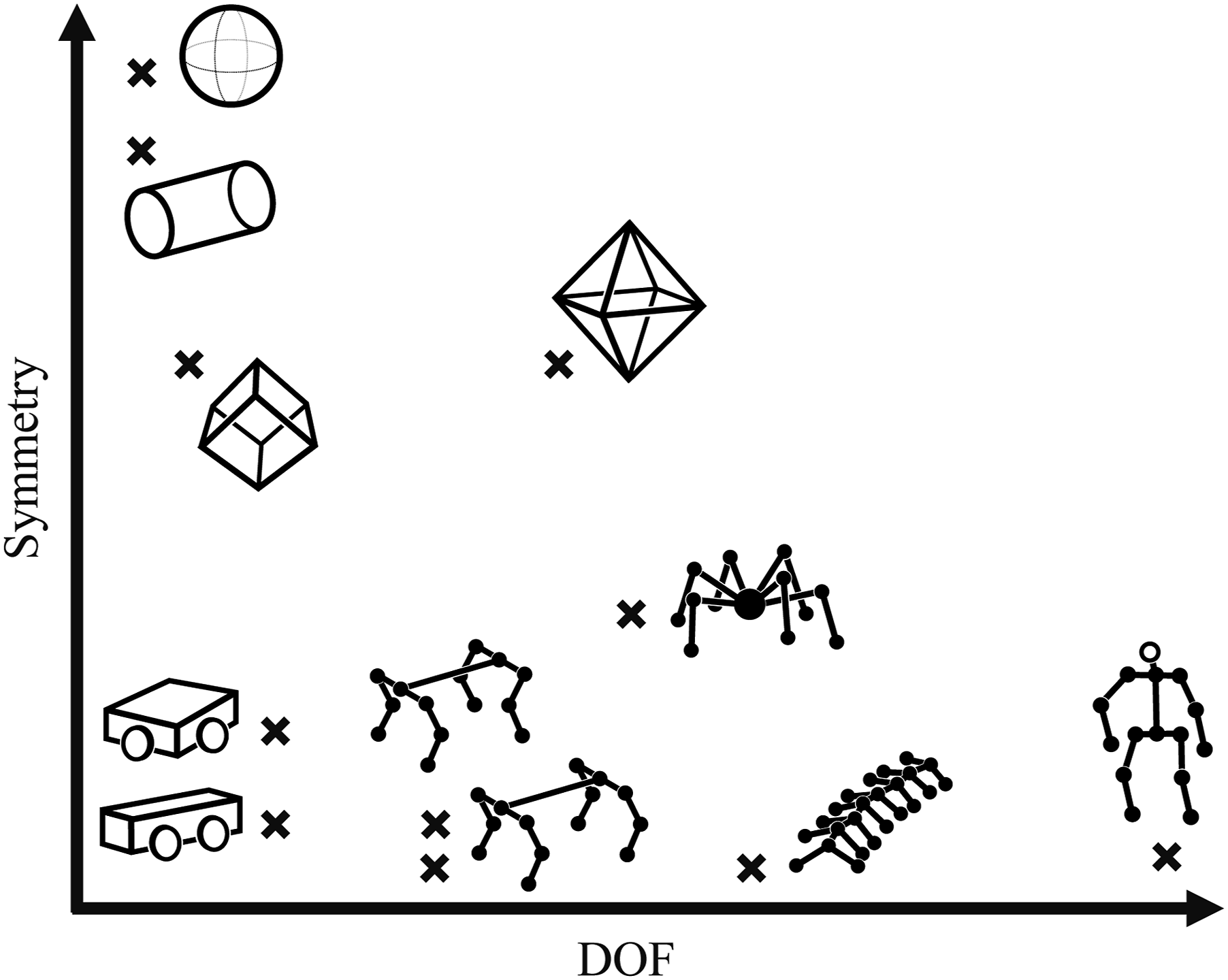
This influence of structural symmetry can also be observed in existing robotic platforms. For example, even within quadrupedal robots, modifying the orientation of the hind legs leads to differences in locomotion characteristics, as seen in the comparison between Spot 18 and Solo8, 19 where differences in leg orientation relative to the body lead to distinct locomotion characteristics. These variations indicate that morphological configuration—beyond actuator count—plays a significant role in determining system behavior.
In this study, robots are classified into four categories based on the degree and type of symmetry in their body structure: plane-, line-, point-, and perfect symmetry. Details are provided in the following subsection. Among these, point symmetry represents a distinctive configuration in which functional elements are arranged in a manner that preserves structural balance while allowing directional flexibility. This property suggests that point-symmetric robots can achieve a form of orientation-independent operation, not through additional mechanisms, but through the inherent structure of the body itself.
Several point-symmetric and cube-based robotic systems have also been developed. The gyro-cube, 10 a cube-shaped robotic platform, demonstrated dynamic balancing as a three-dimensional inverted pendulum by jumping through self-generated impacts and stabilizing itself via angular momentum exchange. In the field of modular robotics, cube-based robotic modules have also been extensively studied.10–12 Owing to their geometric regularity, such systems provide advantages in modularity, reconfigurability, and scalability.
However, when multiple modules are connected to construct functionally specialized robotic systems, strict point symmetry is typically sacrificed in favor of task-oriented structural arrangements, resulting in globally asymmetric morphologies. Consequently, although these studies successfully exploited geometric regularity for reconfiguration and stabilization, point symmetry itself has not been sufficiently investigated as a persistent body design principle for realizing orientation-independent locomotion and manipulation within a single integrated robotic platform.
Based on this viewpoint, we develop a point-symmetric legged mobile robot that maintains operability even after falling. Rather than relying on specialized recovery behaviors, the proposed system exploits structural symmetry to enable consistent functionality through posture-dependent role assignment. The main contributions of this work are summarized as follows: • A design framework that positions point symmetry as a fundamental principle for robotic body design • A method for dynamically assigning functional roles to identical legs based on posture • Experimental validation demonstrating consistent behavior across multiple orientations
Robot development
Robot morphologies
As discussed in the Introduction, robotic systems can be organized according to the degree and type of geometric symmetry in their body structure. Figure 1 illustrates representative robotic morphologies classified along this perspective. Based on this concept, in this study, robots are categorized into four symmetry classes, as illustrated in Figure 2. Classification of robots based on geometric symmetry.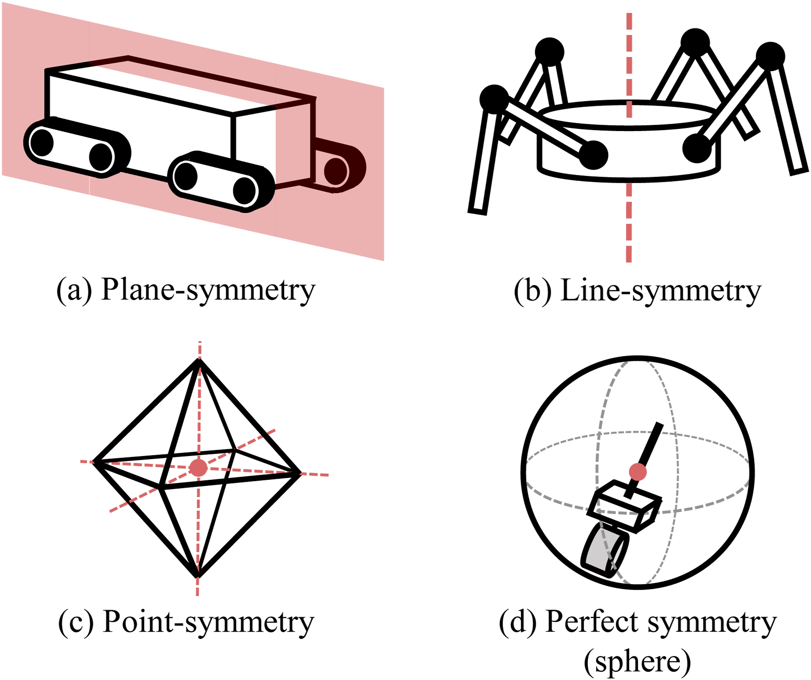
(a) Plane-symmetric robot
Plane-symmetric, or reflectional symmetric robots were mentioned in the former study, 2 and many existing robots fall into this category. Representative examples include quadrupedal robots inspired by animals such as dogs and cats,16–19 humanoid robots,22–25 crawler robots,26–28centipede-like multilegged robots, 21 and various wheeled robots.14,15 These robots generally possess rectangular body and exhibit bilateral and/or fore–aft reflectional symmetry. For instance, the quadrupedal robots presented in reference 19 exhibited both bilateral and fore–aft symmetry, and also has partial vertical symmetry.
(b) Line-symmetric robot
Line-Symmetric, or radial-symmetric robot was proposed in the former study. 2 This category includes spider-like multilegged robots, 20 omnidirectional mobile robots equipped with omni-wheels, 13 and cylinder-type robots.8,9 These robots are typically cylindrical and exhibit rotational symmetry about a single central axis.
(c) Point-symmetric robot
Point-symmetric robots exhibit rotational symmetry about multiple axes intersecting at the robot center, which may also be regarded as inversion symmetry. Representative examples include cube-shaped robots such as gyro-cube 10 and modular cube-based robotic systems.11,12
(d) Perfectly symmetric robot
Spherical robots5–7 fall into this category. A sphere possesses infinite rotational symmetry around any axis through its center, thereby exhibiting perfect symmetry. Such robots primarily locomote by rolling rather than using legs, and their functional capabilities are inherently constrained by their structure. Multilegged robots enclosed within spherical shells have also been developed, 29 although these systems typically lose perfect symmetry due to the asymmetric placement of internal drive units and actuators.
Among these categories, this study focuses on point-symmetric robots as a basis for achieving orientation-independent functionality.
Point-symmetric rigid body
Regular polyhedra exhibit multiple reflectional and rotational symmetries. 30 In this study, we adopt regular polyhedra as point-symmetric rigid body for robots, with one manipulator attached to each face. This configuration enables the robot to maintain operability even after falling and experiencing changes in body orientation caused by environmental effects. Regardless of the body orientation, the robot can adopt a posture in which the manipulators in contact with the ground function as legs.
Five types of regular polyhedra exist (Figure 3), and all were considered as potential structures for the proposed robot. Robots based on the tetrahedral or hexahedral structure have three or fewer manipulators (legs) capable of making ground contact. Consequently, such robots rely solely on two stance legs and one swing leg, making stable locomotion difficult. On the other hand, robots based on the octahedral, dodecahedral, or icosahedral structure allow for ground contact with four or more manipulators. However, these configurations significantly increase mechanical complexity and development costs. Regular polyhedra.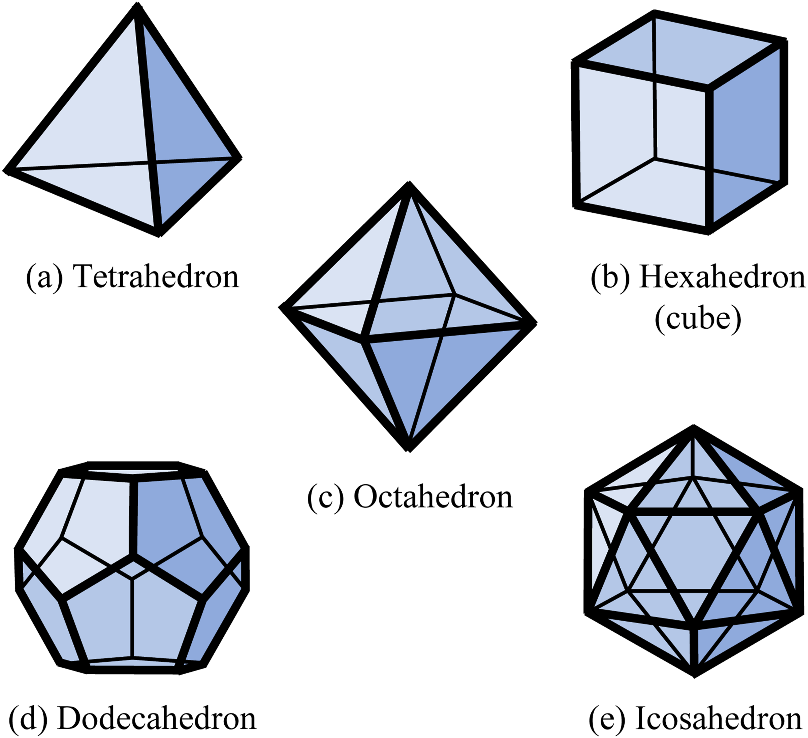
Considering the trade-off between stability and complexity, the regular octahedron was selected as the rigid body structure for the actual robot development in this study.
Manipulator mechanism
The design specification of the proposed robot includes mobility as well as grasping capability. Accordingly, each manipulator needs to function both as a leg and as an arm.
To reduce mechanical complexity and development costs, the degrees of freedom (DOF) of each manipulator are limited to two, rather than three as commonly employed in quadrupedal robots. Consequently, two motors are allocated per manipulator, resulting in a total of 16 motors for the entire robot.
A four-bar link mechanism is introduced to ensure structural strength. Specifically, a parallel crank mechanism forms the base, enabling vertical motion essential for legged locomotion. Furthermore, the link lengths are configured such that the trajectory of the manipulator tip envelops the robot’s center.
Figure 4 illustrates schematic diagrams of the parallel crank mechanism (left) and the designed link mechanism (right). In this figure, link AB is fixed, with joint A serving as the rotation axis of the motor driving the mechanism. Point B is connected to the centroid of the body face, and serves as the rotation axis of the motor rotating entire manipulator. As shown in the figure, when link BP rotates about joint B as the fulcrum, the position of joint Q is closer to link AB in the designed linkage mechanism than in the parallel crank mechanism. In other words, by applying this design, the manipulator is expected to function not only as a leg, but also as an arm that grasp and hold an object. Manipulator mechanisms.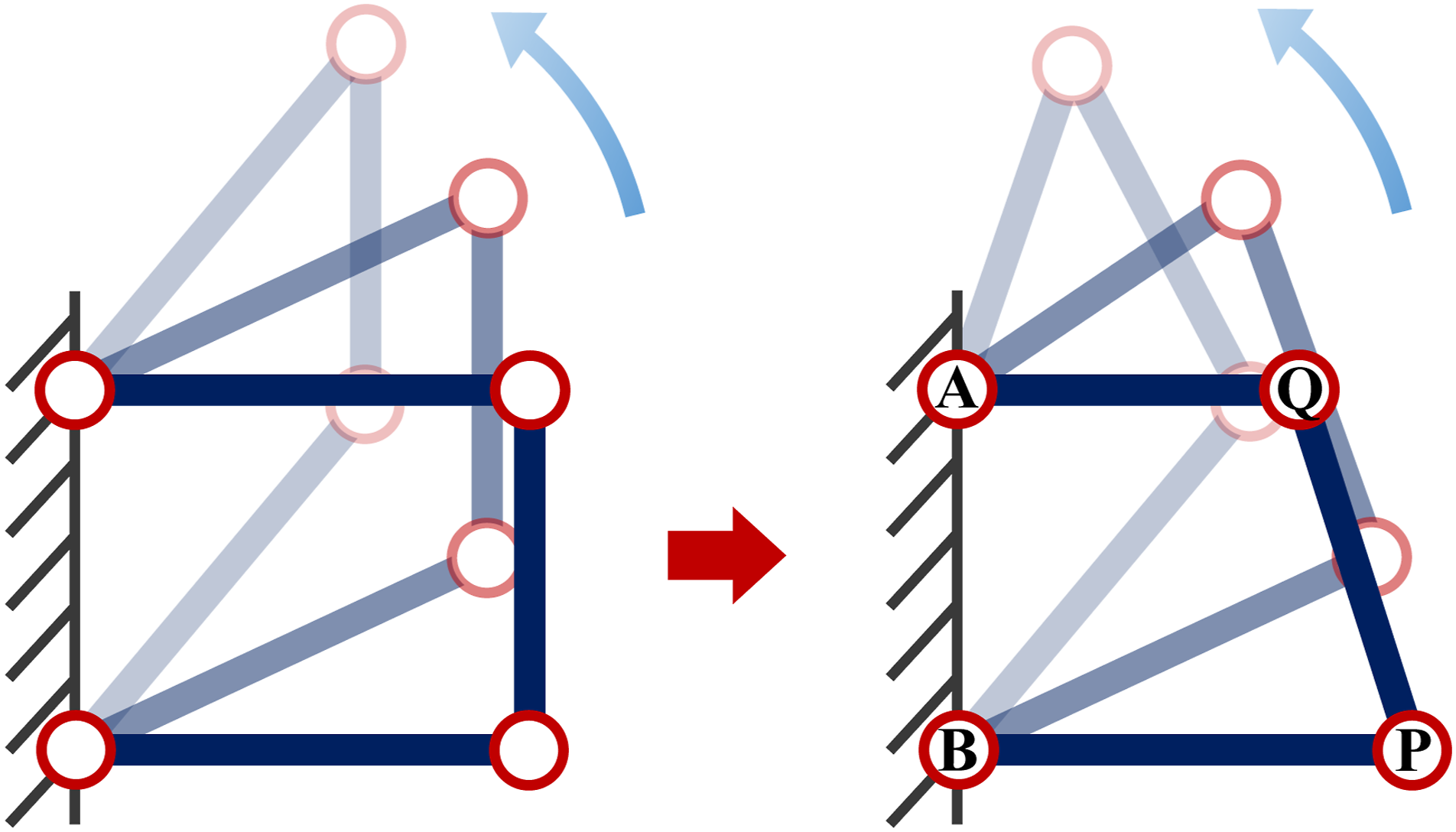
Detailed kinematic trajectory analyses of the manipulator are provided in the Supplementary Information.
Robot kinematics
Center body
Thanks to the geometric symmetry of the body, the kinematics of the proposed robot can be derived in a straightforward manner, that is to be determine a position vector. The position vector of the centroid of face i, denoted by

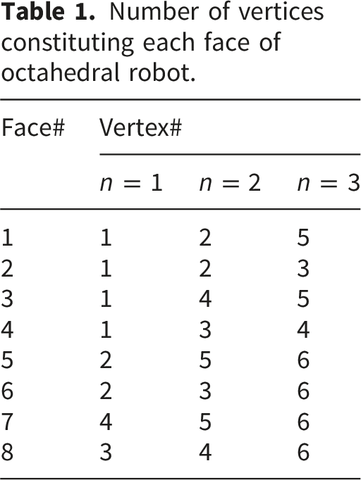
The numbering of the vertices and faces of the regular octahedral body, together with the robot coordinate frame, are shown in Figure 5(a). And the vertex combinations forming each face are listed in Table 1. Coordination of octahedral robot. Number of vertices constituting each face of octahedral robot.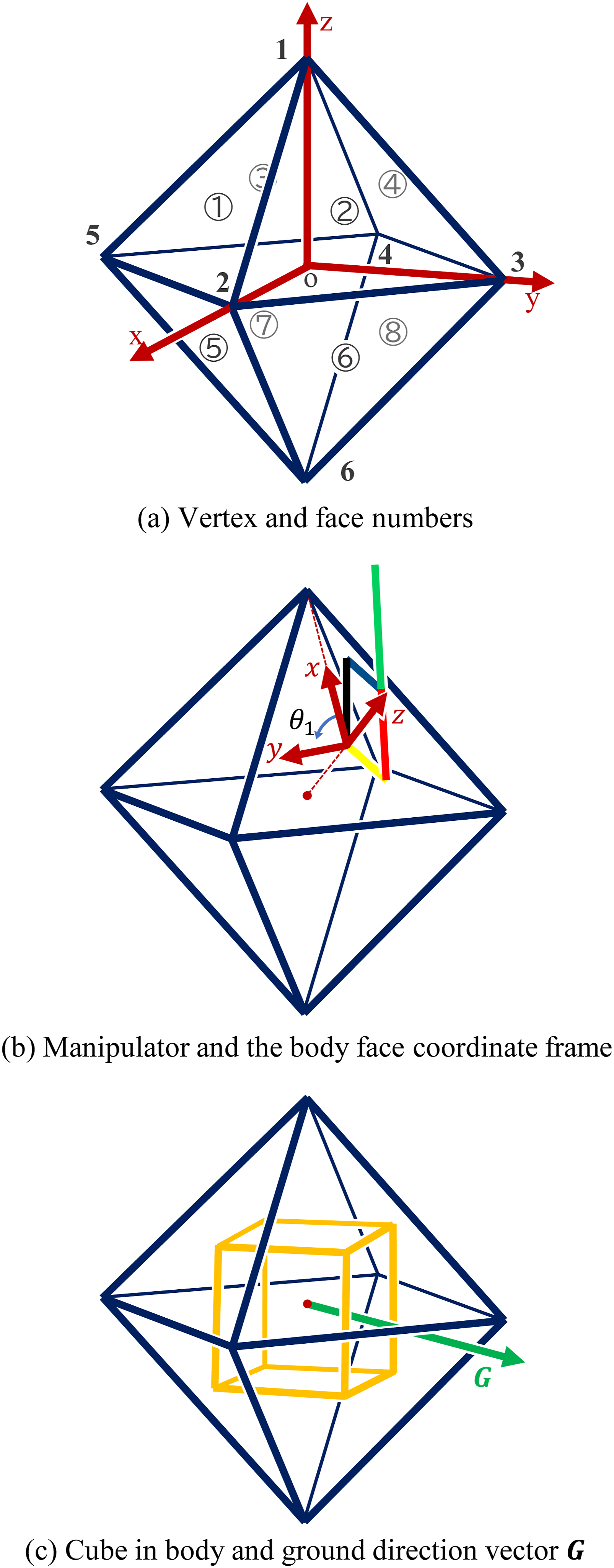
Manipulators
We define the coordinate frame for the body face as follows. The centroid of each face is set as the origin. The z-axis is defined as the direction from the robot coordinate frame origin to the body face coordinate frame origin, the x-axis is defined as the direction from the body face coordinate frame origin to the vertex with the lowest index on the corresponding face, and the y-axis is given by the outer product of the z- and x-axes. This frame of octahedral robot is illustrated in Figure 5(b).
Each manipulator lies on the x–z plane of the body face coordinate frame, as shown in the figure. The position vector of the manipulator tip 
Owing to the geometric symmetry of the body, modifications to the manipulator mechanism or structure affect only the manipulator kinematics, while the body kinematics remain unchanged. Furthermore, when the body is replaced by another regular polyhedron (see Figure 3), the tip position of each manipulator can be obtained by simply redefining the vertices and related elements following the same formulation.
Implementation in actual robot
The developed robot is shown in Figure 6. Each faces of the regular octahedron is treated as an identical module, and the entire robot is fabricated by duplicating this module, as illustrated in Figure 6(a). Because the module shapes are homogeneous, this modular design significantly reduces production costs associated with materials, machining, and assembly. Overview of the developed robot.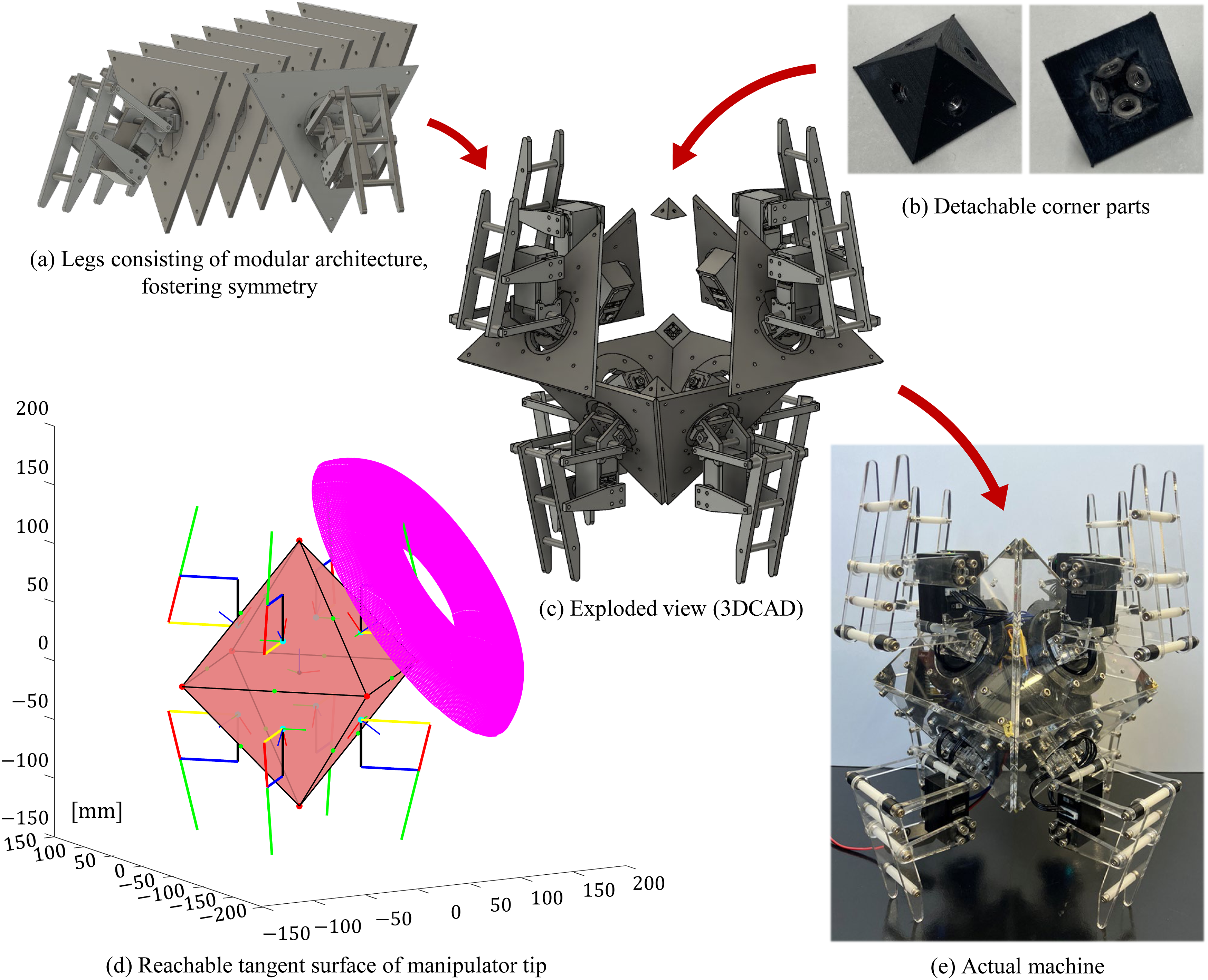
For module connections, dedicated corner parts with embedded nuts were developed (Figure 6(b)). These parts function similarly to a female-threaded components, improving both assembly efficiency and maintainability. Most of the body and mechanical components are made of 4mm-thick acrylic sheets, while the remaining parts are primarily resin to reduce overall weight. Components requiring complex geometries are fabricated using a 3D printer.
The free-shaft side of each motor (opposite the output shaft) is utilized to minimize torsional loads applied to the manipulator mechanism and to prevent plastic deformation of the acrylic components. In addition, selected module holes are enlarged to allow internal cable routing for power supply.
These implementation measures contribute to significantly reduction in the time required for preliminary experiments and facilitate rapid prototyping and testing.
System configuration
Hiwonder’s LX-15D intelligent serial bus servo motors are used to rotate the manipulators and drive the mechanisms. These servo motors support daisy-chain connections, enabling simultaneous command transmission to multiple units. Each motor is assigned a unique ID, allowing distinct commands to be addressed individually.
A schematic diagram of the system configuration is shown in Figure 7. The motors are controlled by an Arduino Uno R3 microcontroller (hereinafter “Arduino”) via the company’s dedicated serial bus servo controller. The Arduino first sends control commands to the servo controller through serial communication, after which the controller converts the signals into transistor–transistor logic (TTL) signals and transmits them to the corresponding motors. In this configuration, motors with odd-numbered IDs control the rotation of the manipulators, while motors with even-numbered IDs actuate the mechanism; together, each pair of motors constitutes a single manipulator. System configuration. The configuration is scalable according to the number of motors.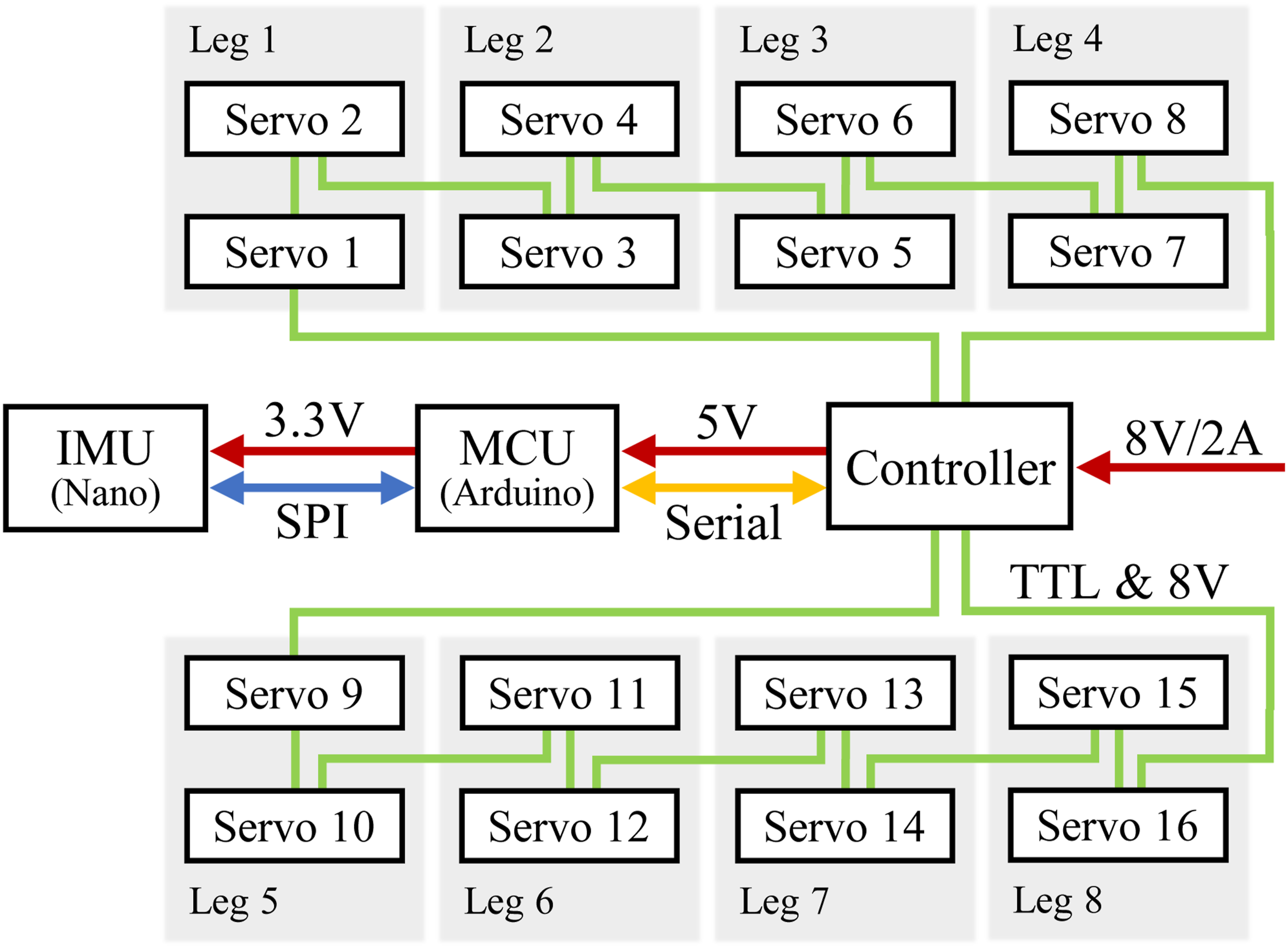
Fall detection is implemented using an inertial measurement unit (IMU) integrated into an Arduino Nano 33 BLE Sense board (hereinafter “Nano”). The Nano estimates the body orientation and communicates this information to the Arduino via serial peripheral interface (SPI) communication.
Power is supplied as follows: 8V/2A (maximum) is provided to the servo controller, 5V is supplied from the controller to the Arduino, and 3.3V is supplied from the Arduino to the Nano. Motor power is also distributed through the daisy-chain connections. As the number of motors increases, power shortages may occur; therefore, two independent daisy-chain loops are employed. One loop connects the controller to servos 1–8 in sequence and then returns to the controller, while the other loop connects servos 9–16 in the same manner. This configuration stabilizes the power supply and ensures reliable operation of all motors.
Kinematic motion control
Fall-detection
Point symmetry enables locomotion control to be formulated using a minimal, orientation-independent representation based on a single reference vector. For fall detection, the posture of the robot is defined as follows. As illustrated in Figure 6(e), when the posture in which four manipulators simultaneously contact the ground is defined as the basic posture, the robot body can assume six distinct postures corresponding to the six vertices of the octahedron. Each posture is uniquely identified by the vertex number of the uppermost vertex, as defined in Figure 5(a).
To formalize this representation, consider a cube formed by connecting the centroid of each face of the octahedral body. At any given moment, a vector
This concept can be generalized to other polyhedral shapes. By connecting the centroids of their faces to form a corresponding auxiliary polyhedron, a unique and discrete posture representation can be obtained in the same manner.
In implementation, the posture can be determined directly from the vertex vectors and the ground direction vector. Specifically, the vertex with the largest angle between each vertex vector and the ground direction vector represents the posture of the robot.
Here, let 

This formulation provides a unique and computationally efficient identification of the robot posture, since the ground direction vector intersects a single face of the auxiliary polyhedron, which determines a unique opposing vertex.
Algorithm for role determination
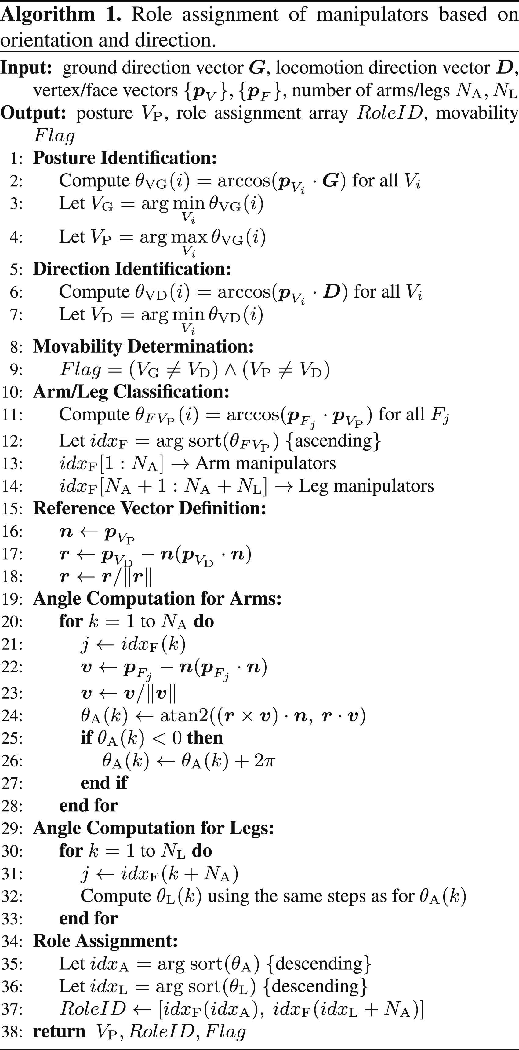
In this study, we developed a method (Algorithm 1) for assigning functional roles (arm/leg) and determining the circumferential ordering of manipulators in polyhedral robots based on their posture and locomotion direction. Specifically, the algorithm computes: (i) the current posture vertex VP, (ii) the movability Flag, and (iii) the role assignment array RoleID.
All vectors are defined in the robot body coordinate frame, and are assumed to be unit vectors. The vertex vectors
This algorithm takes as input the ground direction vector
Posture identification (lines 1–4)
The angles θVG between each vertex vector
Direction identification (lines 5–7)
Similarly, the angles θVD between each vertex vector
Moveability determination (lines 8, 9)
If VD coincides with either VG or VP, the robot is unable to generate effective locomotion in the desired direction because the locomotion direction becomes aligned with either the ground-facing direction or the vertically upward direction of the robot. In this case, the movability Flag is set to false.
Arm/leg classification (lines 10–14)
The angles
Reference vector definition (lines 15–18)
The vertex vector 
The resulting normalized vector
Angle computation for arms (lines 19–28)
Each face vector 
The circumferential angle θA of these vectors are computed with respect to the reference vector 
The function atan2 (x, y) returns an angle in (−π, π], which is then converted to the range [0, 2π).
Angle computation for legs (lines 29–33)
The circumferential angle θL of leg faces are computed using the same procedure.
Role assignment (lines 34–37)
The angles θA and θL are independently sorted in descending order, yielding the corresponding index sets idxA and idxL. Role IDs are assigned such that the indices increase in the clockwise direction when viewed along the positive
Since the proposed algorithm only requires geometric direction vectors associated with vertices and faces, it can be applied to polyhedral robots with different geometries. The resulting RoleID provides a posture-dependent manipulator ordering that can be directly used in the control phase to determine which manipulators are actuated to generate motion.
The computational cost of the algorithm was evaluated on several microcontrollers, confirming its suitability for real-time applications (see Table S5 in the Supplementary Information).
Motor control for locomotion
For locomotion, the robot advances by sequentially actuating the manipulator rotation and the mechanisms, following a walking gait pattern analogous to that of quadrupedal animals.
31
In this gait, the swing phase of each leg is shifted by π/2 relative to the others, resulting in a quarter-period phase difference among the four legs. Accordingly, the phase shift corresponds to ωT/4, and the target angular position for the k-th leg is given as
The target angular positions,
Results
Simulation results
Simulations were conducted to evaluate locomotion performance and posture transitions during falling events. Dynamic simulations were implemented using Simscape Multibody in MATLAB Simulink. Figure 8 shows representative snapshots of the octahedral robot during a fall, and a corresponding movie is available online. Simulation of posture switching after a fall (movie available online).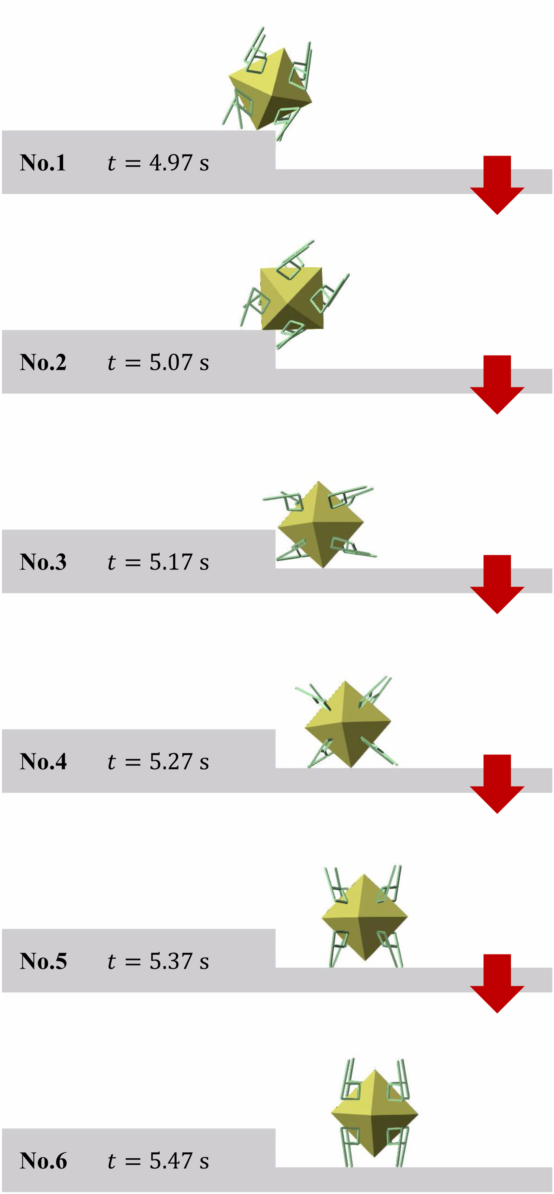
Locomotion was achieved using four manipulators in contact with the ground. Due to the structural characteristics of the robot and the limited 2-DOF configuration of each leg, direct upward swinging motion along the locomotion direction is not feasible. Nevertheless, stable locomotion was observed under these constraints in specific configurations.
A fall was induced by introducing a step on a moving plane. Fall detection was performed using Algorithm 1, which evaluates the robot’s posture based on the angular relationship between vertex direction vectors and the ground direction vector. A change in the identified posture indicates a transition event such as falling.
As shown in Figure 8 (snapshots 1–6), the robot contacts the step and begins to fall (No.1), followed by a sequence of body rotations (Nos.2–5), which is also reflected in the rotation angle variations (Figure 9(a)). These changes correspond to variations in the ground direction vector in the robot coordinate frame (Figure 9(b)), leading to an update in posture identification (Figure 9(c)). Time histories of the robot orientation and the corresponding outputs of algorithm 1 in simulation.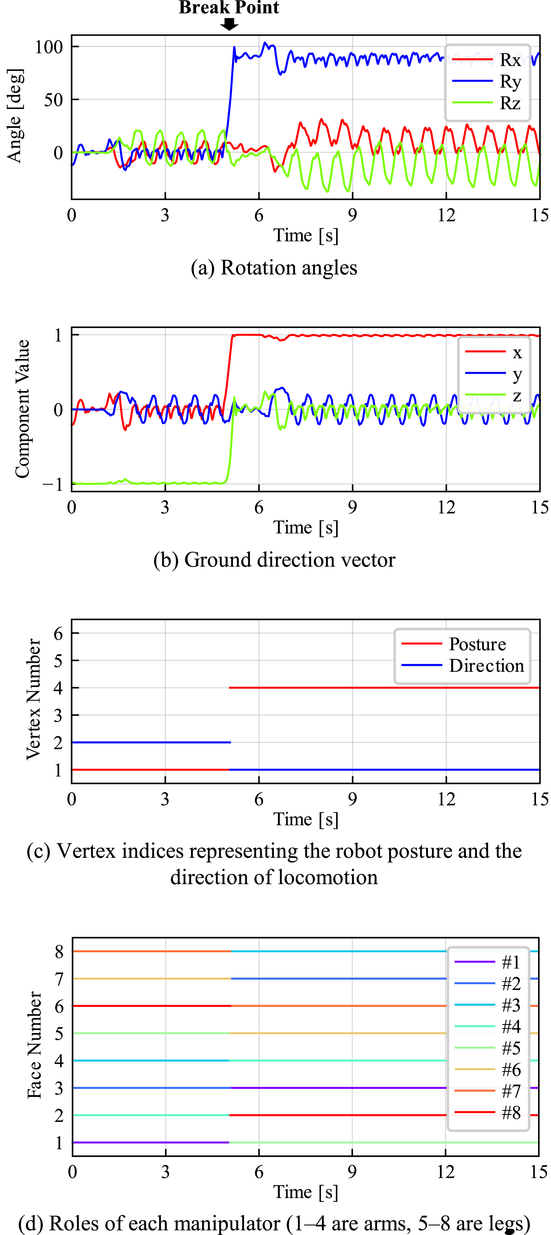
Simultaneously, the relative configuration between each face and the ground is updated, resulting in a reassignment of arm and leg roles (Figure 9(d)). Based on the updated roles, the robot transitions to a base posture corresponding to the new orientation (No.6) and resumes locomotion.
The same procedure was applied to dodecahedral and icosahedral robots by redefining their vertex and face sets. In all cases, the robots exhibited similar behavior: encountering a step, undergoing reorientation, transitioning to a valid posture, and resuming motion. These snapshots and data, together with the additional data for the octahedral robot, are provided in the Supplementary Information (Figures S4–S15).
To ensure stable ground contact across different polyhedral configurations, an offset angle was introduced in the leg mechanism. This offset was applied to θ2 (see Figure 4), corresponding to the rotation angle of the actuator driving the mechanism.
During locomotion after falling, fluctuations in the identified Direction (i.e., the vertex most aligned with the locomotion direction) were observed. Direction fluctuations were observed 0, 2, and 10 times for the octahedral, dodecahedral, and icosahedral robots, respectively. This indicates that the identified Direction was affected by oscillatory body motion during locomotion. The corresponding variations in rotation angles can be seen in Figure 9(a) and (c) for the octahedral robot.
Hardware experiment results
Arm and leg functions in multiple postures
Hardware experiments were conducted to evaluate the arm and leg functionalities of the manipulators in multiple body postures. The manipulators successfully demonstrated grasping when functioning as arms and locomotion when functioning as legs. Figure 10 shows snapshots of the experiments, and a corresponding movie available online. Hardware experiments of grasping and locomotion (movie available online).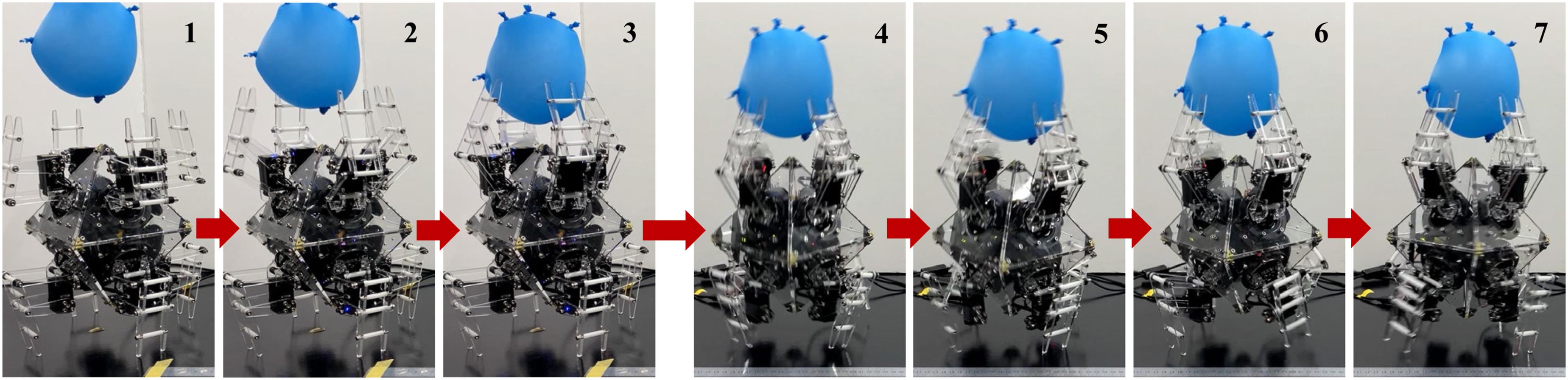
As in the simulations, four manipulators in contact with the ground were used for locomotion, while the remaining four manipulators, which were not grounded, were used for grasping. Snapshots Nos. 1–3 show grasping motions, and Nos. 4–7 show locomotion. During grasping, activation of the mechanism generated an inward trajectory of the manipulator tips, enabling successful object grasping. During locomotion, the robot advanced by sequentially actuating the manipulator rotation and the mechanisms according to the motion control method described in the “Motor Control for Locomotion” subsection.
Additional experiments confirmed that these motions could be executed in all body orientations. Although continuous locomotion was restricted in some postures due to motor range limitations, the robot successfully executed crouching motions in all orientations.
To provide a basic quantitative measure of locomotion performance, we evaluate the average locomotion speed over a predefined distance. Across 10 independent trials, the robot achieved an average speed of 0.092m/s. Note that this metric is influenced by actuator performance; therefore, it is reported here primarily to indicate the operational timescale rather than to claim optimality.
Detailed results are provided in the Supplementary Information (Table S2 and S3).
Motion after fall
Experiments were conducted to evaluate the robot’s behavior after a fall. Starting from the basic posture (Figure 6(e)), the robot was intentionally destabilized to induce a fall. A stick equipped with a hooked claw was used to engage one of the legs and apply an external disturbance, thereby causing the robot to fall. Figure 11 shows snapshots of the experiment, and a corresponding movie is available online. Hardware experiments of posture switching after a fall (movie available online).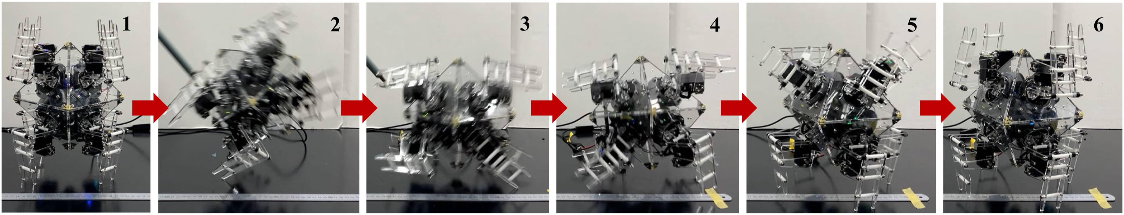
As observed in the simulations, once the robot had fallen, the manipulators and mechanisms were activated, enabling the robot to transition into the basic posture according to the newly detected body orientation. The robot’s body orientation was recognized by calculating the ground direction vector from IMU data, which allowed for posture determination and fall detection.
To provide a quantitative measure of recovery performance after a fall, we evaluate the recovery time. Across 10 independent trials, the average recovery time was 2.26s, with very small variation across trials, indicating consistent recovery behavior. Note that this metric is influenced by actuator performance; therefore, it is reported here primarily to indicate the operational timescale rather than to claim optimality. Detailed results are provided in the Supplementary Information (Table S4).
Discussion
Switching manipulator functions
The experimental results demonstrated that the proposed robot is capable of both grasping and locomotion, even when its body orientation changes significantly. This indicates that each manipulator simultaneously fulfills two distinct functional roles: it acts as a leg during locomotion and as an arm capable of enveloping an object during grasping. This dual functionality is achieved through a multimodal structural design, in which a single physical mechanism can seamlessly transition between different operational modes without requiring additional actuators or reconfiguration.
Although the role assignment and control strategy are described in the previous sections, an important insight is that the functional switching mechanism is fundamentally governed by the geometric properties of the system. Because all manipulators are arranged equivalently with respect to the robot’s center, no manipulator is inherently assigned a fixed role. Instead, the roles of the manipulators are dynamically determined based on the relative configuration between each face and the ground, together with the locomotion direction. This allows the system to reinterpret identical hardware components as either legs or arms without requiring explicit structural differentiation.
Simply attaching manipulators to a point-symmetric body would generally break the geometric symmetry, thereby reducing the robot’s ability to exploit symmetry-induced invariances in motion and control. In contrast, the proposed design demonstrates that symmetry can be preserved—or functionally recovered—by embedding multimodality within components that are themselves geometrically asymmetric. Rather than enforcing symmetry strictly at the morphological level, the robot maintains functional symmetry through coordinated mode switching across all manipulators.
This perspective suggests an alternative design strategy for robotic systems: symmetry need not be achieved solely through rigidly symmetric structures, but can instead emerge from the collective behavior of multimodal components. Such an approach is particularly beneficial for robots that require both high mobility and versatile manipulation capabilities in changing environments.
Robot symmetry
In this study, the kinematics of robots based on regular octahedral, dodecahedral, and icosahedral bodies were derived using a unified formulation. All of simulations applying the same control framework to these different body shapes revealed that the highly structured point-symmetry of regular polyhedra facilitates a simple and systematic derivation of kinematics, even as the number of faces or legs increases.
The modular manufacturing approach—where each face is implemented as an identical unit—further enhances design scalability. Because each module shares the same geometry and functionality, this methodology can be directly extended directly to other polyhedral configurations without modifying the underlying control architecture. As a result, both hardware design and software implementation scale naturally with the number of modules.
These findings indicate that point-symmetric robots exhibit strong scalability in terms of both mechanical structure and control design. Their symmetry reduces development complexity and enables systematic formulation of kinematics.
However, it should be noted that continuous locomotion was successfully achieved only in a small subset of the tested configurations. In the remaining cases, locomotion could not be sustained. This limitation is primarily attributed to hardware constraints, in particular the restricted range of motion of the actuators used in the current prototype.
In configurations where locomotion failed, the actuators were often positioned near the limits of their motion range, which prevented the legs from generating sufficient forward and backward swing. As a result, the system was unable to produce the periodic motions required for continuous locomotion.
These limitations are not considered fundamental to the proposed design principle. In future iterations, they could be addressed by employing actuators capable of continuous rotation, together with appropriate measures (e.g., slip rings) to prevent wiring issues.
To partially mitigate this limitation in the current prototype, a crouching motion was introduced as an alternative locomotion strategy, which enabled operation across all orientations.
The robot’s posture can be uniquely determined based on a single reference vector. However, this formulation also implies that fluctuations in the identified states become more likely as the number of discrete posture categories increases. In the present experiments, the observed Direction fluctuations were primarily caused by oscillatory body motion during locomotion. Because these fluctuations were transient, the identified state consistently returned to the correct state within a short period, and their impact on locomotion performance was negligible.
It should also be noted that the number of distinguishable postures of a regular polyhedral robot is not determined by the number of faces, but rather by the number of faces of the auxiliary polyhedron formed by connecting the centroids of the original faces, which corresponds to the number of vertices of the original polyhedron. Thus, the icosahedron, despite having the largest number of faces, does not necessarily exhibit the highest frequency of state fluctuations.
Accordingly, while the results suggest that point-symmetric design can provide advantages in robustness to posture changes and simplicity of kinematic control under the tested conditions, the current evaluation is limited by the prototype’s hardware constraints, and further validation using improved implementations is required.
Conclusion
In this study, we developed a regular-octahedron-shaped robot as a point-symmetric legged mobile platform and investigated its kinematic and functional properties. Experiments demonstrated that each manipulator can alternately function as a leg for locomotion and as an arm for grasping, enabling consistent operation regardless of the robot’s body orientation. Furthermore, the robot successfully detected falls using an IMU and autonomously transitioned to an appropriate posture to a newly identified orientation, allowing continued operation without external intervention.
The kinematic formulation and motion control framework proposed in this work exploit the geometric symmetry of the body and enable a minimal, orientation-independent description of motion. Because the control strategy relies on simple geometric relationships rather than posture-specific rules, it is expected to be applicable not only to point-symmetric robots but also to a broader class of robotic systems that can leverage geometric symmetry.
However, evaluating the applicability of the proposed robot in uncertain environments, as well as the development of hardware capable of executing the full range of motions without actuator limitations, remain significant directions for future work.
To sum up, this study suggest that point-symmetric design has the possibility to improve robustness to posture changes and simplicity of kinematic control, and highlights inherent functional advantages.
Supplemental material
Supplemental material - Development of point-symmetric modular legged mobile robot capable of operation after falling
Supplemental material for Development of point-symmetric modular legged mobile robot capable of operation after falling by Tomoya Yoshii and Yusuke Ikemoto in International Journal of Advanced Robotic Systems.
Footnotes
Consent to participate
There are no human or animal participants in this article and informed consent is not required.
Funding
The authors disclosed receipt of the following financial support for the research, authorship, and/or publication of this article: This work was supported in part by JSPS KAKENHI Grant Number JP23H03480.
Declaration of conflicting interests
The authors declared no potential conflicts of interest with respect to the research, authorship, and/or publication of this article.
Data Availability Statement
All data relevant to this study are available from the corresponding author on request.
Supplemental material
Supplemental material for this article is available online.
References
Supplementary Material
Please find the following supplemental material available below.
For Open Access articles published under a Creative Commons License, all supplemental material carries the same license as the article it is associated with.
For non-Open Access articles published, all supplemental material carries a non-exclusive license, and permission requests for re-use of supplemental material or any part of supplemental material shall be sent directly to the copyright owner as specified in the copyright notice associated with the article.