






Abstract
Motor-propeller systems are widely used in Unmanned Aerial Vehicles (UAVs) and Autonomous Underwater Vehicles (AUVs) for thrust generation and motion control. However, many practical platforms do not equip force sensors or encoders because of additional cost, weight, and integration complexity, making rapid thrust tracking without sensing a challenging problem. Existing open-loop thrust control strategies commonly assume an instantaneous thrust response and therefore suffer from significant transient errors and response delays when thrust commands change rapidly or when the propulsion system has large inertia. To address this issue, this paper proposes a data-driven sensorless rapid thrust control strategy for motor-propeller systems. The proposed approach establishes a neural-network-based data-driven model that predicts the thrust at the next step from previous control inputs and estimated thrust states without requiring online sensing. The learned model is integrated with model predictive control (MPC) and a mode-switching mechanism to dynamically determine aggressive control inputs that improve thrust responsiveness while maintaining stability. Experiments are conducted on a real BLDC motor-propeller system and compared with conventional open-loop control and sensor-based PD, MPC, and sliding mode control (SMC) strategies. Results show that the proposed strategy significantly improves transient performance over the widely used open-loop strategy. For tracking a 0.5 Hz square-wave thrust trajectory, the proposed method reduces rise time from 0.141 s to 0.037 s and fall time from 0.122 s to 0.058 s, while also reducing the mean absolute thrust tracking error from 0.314 N to 0.271 N. For randomly varying thrust commands updated every 0.4 s, the proposed method achieves the best overall performance, reducing rise time by 86.0% and fall time by 60.6% compared with the open-loop strategy. Moreover, despite operating without online sensors, the proposed strategy achieves thrust tracking performance comparable to sensor-based PD, MPC, and SMC controllers.
Keywords
I. Introduction
Motor-propeller systems (e.g., a motor-propeller system shown in Figure 1) are widely used for robotic systems such as Unmanned Aerial Vehicles (UAVs) and Autonomous Underwater Vehicles (AUVs), as propulsion systems1–3 to generate thrusts. The motor serves as the power source, driving the propeller to generate thrusts4,5. For control purposes, motor-propeller systems need to rapidly generate target thrusts determined by a controller. It should be noticed that UAVs, including electric Vertical Takeoff and Landing (eVTOL) aircraft, often adopt constant pitch and variable speed thrust control, due to the complexity of pitch control mechanisms.
6
However, if the inertia of motor-propeller systems increases, motor-propeller systems can have a slow dynamic response.
7
Scholars have developed a field-oriented control strategy for accurate and energy-efficient rotation velocity control of motor-propeller systems.
8
Nonetheless, the rapid thrust control of motor-propeller systems is still a challenging problem, due to the lack of sensors (e.g., a force sensor or an encoder), the fluid dynamic drag, and the inertia of the motor-propeller system.
9
Experimental motor-propeller system used in this study, consisting of a T-MOTOR 2216 KV880 BLDC motor, a 10×4.5 fixed-pitch propeller, an Electronic Speed Controller (ESC), and a force-sensing test configuration for thrust measurement and validation.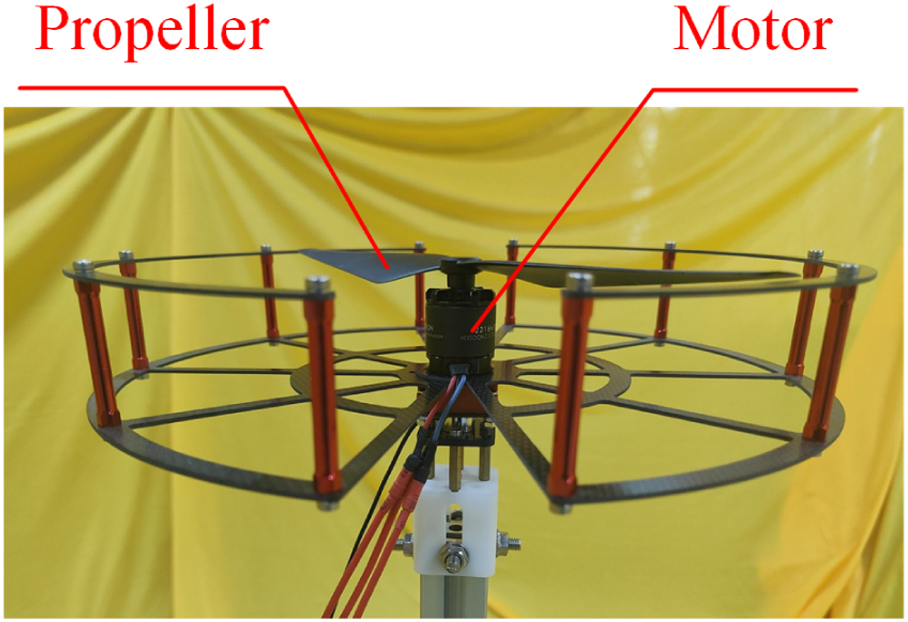
For several existing control strategies designed for the control of a UAV, it is assumed that the response of a motor-propeller system is fast enough and the target thrust can be achieved by the motor-propeller system according to the corresponding control input 10 of a traditional propulsion model. 11 Thus, these UAV control strategies use the existing open-loop thrust control strategy to determine a constant control input in one control cycle corresponding to a target thrust of a motor-propeller system in steady-state and then apply the control input to the motor-propeller system. The time-delay of thrust is addressed by the robustness of UAV control strategies. For instance, scholars have proposed a nonlinear disturbance observer-based controller to reduce the disturbance caused by time-delay, including the time-delay of thrust. 12 However, the fast thrust response assumption doesn’t hold if the target thrust drastically changes or the inertia of a motor-propeller system is large. In this case, the fast thrust response assumption can limit the performance of a UAV. To make the fast thrust response assumption validated for more scenarios in which the target thrust drastically changes or the inertia of a motor-propeller system is large and thus enhances the performance of a UAV, a rapid thrust control strategy for a motor-propeller system is preferred.
In recent years, scholars have developed different control strategies for motors, based on Proportional Integral Derivative (PID) control, 13 Model Predictive Control (MPC), 14 and Sliding Mode Control (SMC). 15 For motor-propeller systems, scholars also have developed thrust tracking strategies. 16 The above-mentioned control strategies require sensors (e.g., a force sensor or an encoder) to measure the force, torque, or rotational velocity of a motor-propeller system and achieve closed-loop control. However, UAVs widely use motor-propeller systems without sensors to avoid additional cost and weight. 17 For motor-propeller systems without sensors, the above-mentioned control strategies cannot be applied. How to control a motor-propeller system without a sensor to rapidly track a target thrust control and reduce response time (i.e.,rapid thrust control) through dynamically adjusting the control input set for the motor-propeller system is an open problem.
The major challenge of the rapid thrust control of a motor-propeller system without a sensor is how to determine the current thrust of the motor-propeller system. For sensorless control problems other than the rapid thrust control of a motor-propeller system without a sensor, scholars have proposed observers and estimators to determine the value of the state to be controlled. Sensorless control strategies have also been developed for systems without sensors available for control purposes in recent years.18,19 Based on a disturbance observer and a Dither Periodic Component Elimination (DPCE) Kalman filter, Phuong et al. have proposed a force estimation strategy to achieve sensorless force control. 20 Xu et al. have focused on bilateral operating systems and developed a bilateral sensorless control strategy based on an adaptive disturbance observer. 21 For industrial robots with high precision without using force sensors, an interaction force estimation strategy that can estimate the interaction forces has been developed in 22 . Fang et al. have developed a wide speed range sensorless control strategy for switched reluctance machines. 23 However, the above-mentioned sensorless control strategies usually require an accurate model to estimate the value of a state (e.g., thrust or angular velocity) to be controlled and have not taken the critical fluid dynamics of a propeller 24 into account. Thus, the above-mentioned sensorless control strategies are limited to addressing the rapid thrust control of a motor-propeller system. Though scholars have established the model of a motor-propeller system incorporating transient properties. 24 The fact that the model incorporating transient properties requires a sensor to measure the initial state (i.e.,initial thrust) of a motor-propeller system can prevent a sensorless control strategy based on the model incorporating transient properties.
Scholars have developed different data-driven modeling techniques to model complex systems.25,26 Due to the progress of neural networks (NNs), NNs have been widely used in data-driven modeling techniques in recent years.27–29 Shang et al. 30 have proposed an end-to-end deep learning method to model a DC-DC bidirectional converter. Xia et al. have proposed a multimodal data-driven strategy to model dioxins generation concentration in the municipal solid waste incineration process. 31 Chowdhury et al. presented data-driven models incorporated into Coriolis flowmeters for mass flow rate measurement based on NN, Gaussian process regression, and support vector machine. 32 By integrating random forest, temporal convolutional network, and deep echo state network, Xue et al. have developed a data-driven model for real-time prediction of nitrogen oxide concentration in a cement clinker calcination system. 33 Peng et al. have focused on robotic manipulators with actuator deadzone interacting with unknown environments and proposed a neural network-based sensorless admittance control strategy. 34 To estimate the external torque, a flatted neural network with an incremental learning algorithm was used. Zhao et al. utilized NNs and Gaussian process regression to build a steering feedback torque model, a key part of a driving simulator. 35 Scholars have proposed the inspiring concept of an NN-based soft sensor 36 and applied soft sensors to applications, including the industrial wastewater treatment process, 37 crude distillation unit, 38 and sulfur recovery unit. 39 The progress in data-driven modeling techniques has paved a way for the sensorless rapid thrust control of motor-propeller systems.
To achieve the rapid thrust control of a motor-propeller system without sensors, this paper develops a data-driven sensorless rapid thrust control strategy (referred to as data-driven thrust control strategy in the following parts) for motor-propeller systems. The authors observe that the thrust of a motor-propeller system mainly depends on recent control inputs 24 and assume that the thrust of a motor-propeller system at the next step can be estimated based on recent control inputs (no measurement required) and the estimated current thrust (no measurement required). Inspired by model-based reinforcement learning40,41 and learning-based MPC,42–44 a data-driven modeling method is proposed for a motor-propeller system to represent the relationship between the thrust at the next step, the current thrust, and previous control inputs. Then, by combining the data-driven model and MPC to establish a predictive thrust control strategy and performing mode-switching 45 between the predictive thrust control strategy and the existing open-loop thrust control strategy, the data-driven rapid thrust control strategy is achieved for the motor-propeller system.
The main novelties and contributions of this paper are as follows. • This paper develops a data-driven sensorless rapid thrust control strategy for a motor-propeller system without sensors to improve the responsiveness of thrust control through dynamically adjusting the control input set for the motor-propeller system. Compared to the existing widely used open-loop thrust control strategy that avoids the rapid thrust control problem by setting the constant control input corresponding to a target thrust, the data-driven thrust control strategy can improve the responsiveness of the thrust control by dynamically adjusting the control input. Compared to existing sensorless control strategies developed for the velocity control or torque control of a motor without taking the fluid dynamics of a propeller into account, the data-driven thrust control strategy focuses on improving the thrust response of a motor-propeller system and takes the effects of the fluid dynamics of a propeller into account by data-driven modeling techniques. • This paper proposes to establish a data-driven model of a motor-propeller system to predict the thrust at the next step according to the current thrust and previous control inputs, based on the observation that the thrust of a motor-propeller system mainly depends on the last few control inputs. With the data-driven model, the current thrust (predicted value), and previous control inputs (true value), the thrust of a motor-propeller system can be predicted approximately without requiring sensors. • This paper conducts experiments based on a real motor-propeller system of a UAV and compares the data-driven thrust control strategy to the widely used open-loop thrust control strategy (without requiring sensors) in UAV control, a Proportional Derivative (PD) thrust control strategy (a force sensor required), an MPC thrust control strategy (a force sensor required), and an SMC thrust control strategy (a force sensor required). The effectiveness of the data-driven thrust control strategy in improving the responsiveness of thrust control is verified and its thrust tracking error and transient response are presented.
The remaining sections of this paper are arranged as follows. Section II defines the problem of sensorless rapid thrust control of a motor-propeller system. A data-driven thrust control strategy for a motor-propeller system is proposed in Section III. Section IV conducts experiments to demonstrate and validate the data-driven thrust control strategy. Finally, Section V summarizes the paper.
II. Problem statement
Although the computational capability of onboard computers and controllers has increased in recent decades and control inputs can be determined in a high frequency (e.g., 50 Hz to 500 Hz), motor-propeller systems can have a slow dynamic response due to fluid dynamic drag and increased inertia. 7 This paper addresses a unified control strategy for a general system of a motor and a constant pitch propeller without sensors (e.g., a force sensor or an encoder) to increase the responsiveness of the thrust control (i.e.,implementing the target thrust determined by a controller) by making full use of control input limits (i.e.,current input limits or voltage input limits). For this purpose, a data-driven sensorless rapid thrust control strategy is developed, taking the following requirements into account inspired by. 45
III. Data-driven sensorless rapid thrust control strategy
This study focuses on a practical sensorless thrust-control framework integrating data-driven modeling and predictive control for real motor-propeller systems. The primary contribution lies in the practical realization of rapid thrust tracking without online sensing, rather than deriving a fully analytical control-theoretic formulation.
To achieve the rapid thrust control of a motor-propeller system without sensors, this section proposes a data-driven sensorless rapid thrust control strategy that combines MPC and a data-driven model of a motor-propeller system based on an NN, inspired by,42–44 to achieve a predictive thrust control strategy, and performs mode-switching 45 between the predictive thrust control strategy and the existing open-loop thrust control strategy. This study doesn’t directly learn an NN-based controller but chooses to combine an NN-based model of a motor-propeller system with MPC, since an NN-based model and MPC combined framework can achieve better robustness and has been successfully applied to the control of a real UAV. 46 The thrust of a motor-propeller system can be controlled by different control inputs, such as current input and voltage input. It should be noticed that this study focuses on a practical control strategy integrating mechanical engineering, electronic, and intelligent computer control for general motor-propeller systems without sensors, rather than a novel controller in control theory.
The steps of the implementation of the data-driven thrust control strategy are summarized in Figure 2. The data-driven thrust control strategy includes two phases - offline motor-propeller system modeling phase and online thrust control phase. In the offline motor-propeller system modeling phase, one can build an NN-based model of a motor-propeller system offline based on a force sensor (for data collection but not for thrust control) and data-driven modeling techniques.
47
The NN-based model can predict the thrust at the next step according to the current thrust and previous control inputs. The details of establishing a data-driven model of a motor-propeller system are presented in Section III-A. In the online thrust control phase, a data-driven thrust control strategy can be achieved by integrating the NN-based model into MPC. With the NN-based model and a proper MPC controller, a control input to achieve the target thrust and the predicted thrust can be determined. If the predicted thrust corresponding to a control input to be implemented is larger than a threshold in a rising phase or smaller than a threshold in a descending phase, the data-driven thrust control strategy will adopt the control input according to the conventional open-loop thrust control strategy to improve the performance in steady-state. Section III-B presents the procedures for controlling the thrust of a motor-propeller system based on the data-driven thrust control strategy. It should be emphasized that current limits or voltage limits should be taken into account in both the offline motor-propeller system modeling phase and the online thrust control phase. Overall framework of the proposed data-driven sensorless rapid thrust control strategy, including offline neural-network-based modeling and online predictive thrust control.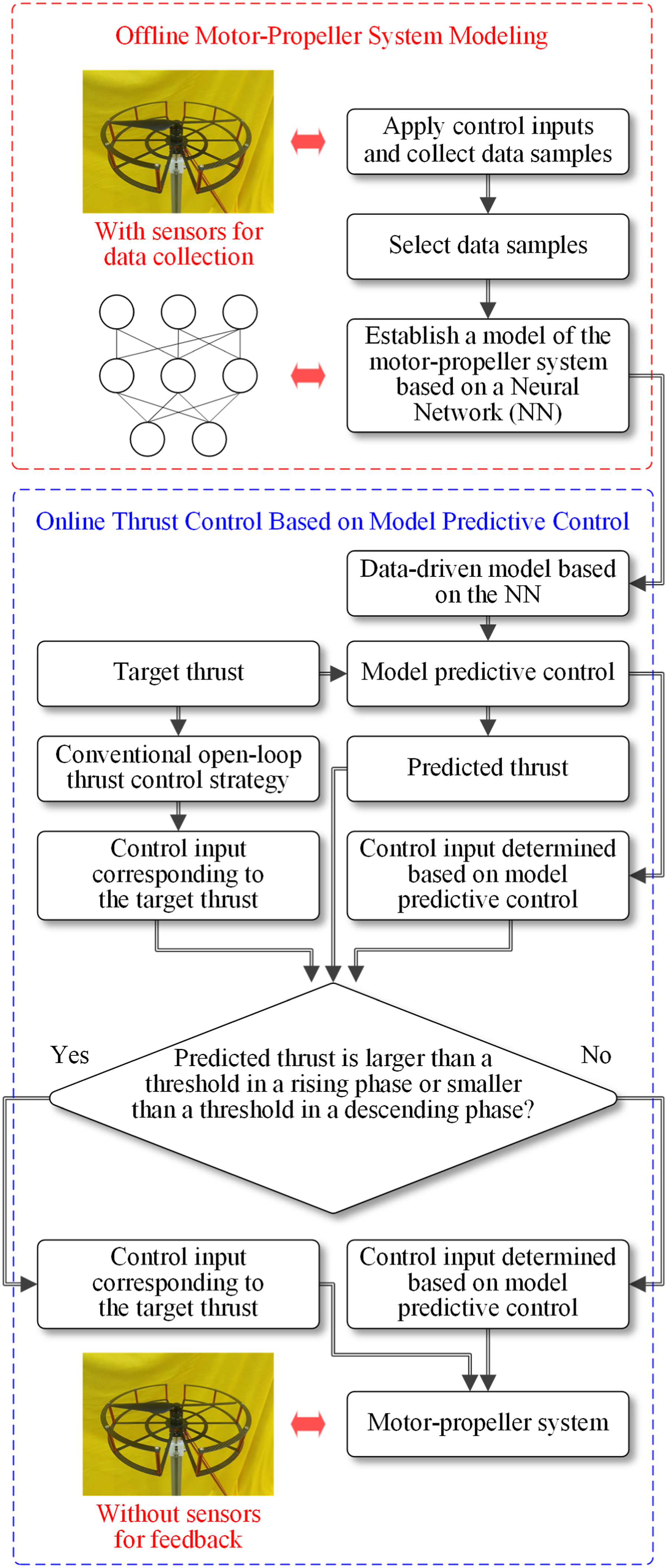
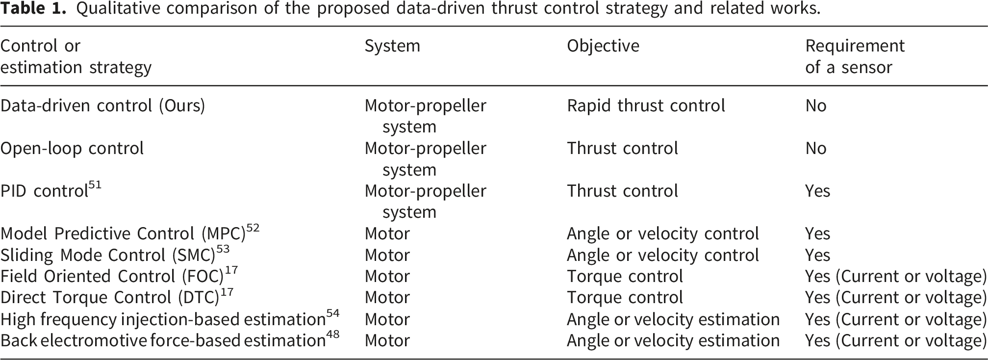
Qualitative comparison of the proposed data-driven thrust control strategy and related works.
A. offline motor-propeller system modeling
The steps of establishing a data-driven model of a motor-propeller system are as follows.
Step 1: Data generation
To establish a model that predicts the thrust at the next step based on the current thrust and previous control inputs, data samples that include the current thrust, previous control inputs, and the thrust at the next step are required. One can apply several sets of control inputs (e.g., random control inputs) covering the feasible range of control inputs to generate data samples. The current thrust, the series of previous control inputs, and the thrust at the next step should be involved in a data sample. The thrust generated by the motor-propeller system can be recorded by a force sensor. For step t, a data sample including M previous thrusts and P previous control inputs can be defined as
Step 2: Data selection
To improve the accuracy of a data-driven model, the collected data samples are refined to make the data samples used for establishing a data-driven model tend to be uniformly distributed. To refine the collected data samples, one can select data samples according to the Kennard-Stone (KS) method 55 based on the distance between every pair of data samples. The distance can be defined in different ways. For instance, the distance can be defined based on the norm of a vector consisting of the thrusts of a data sample. The selected data samples are used for establishing a data-driven model then.
Step 3: Model establishment
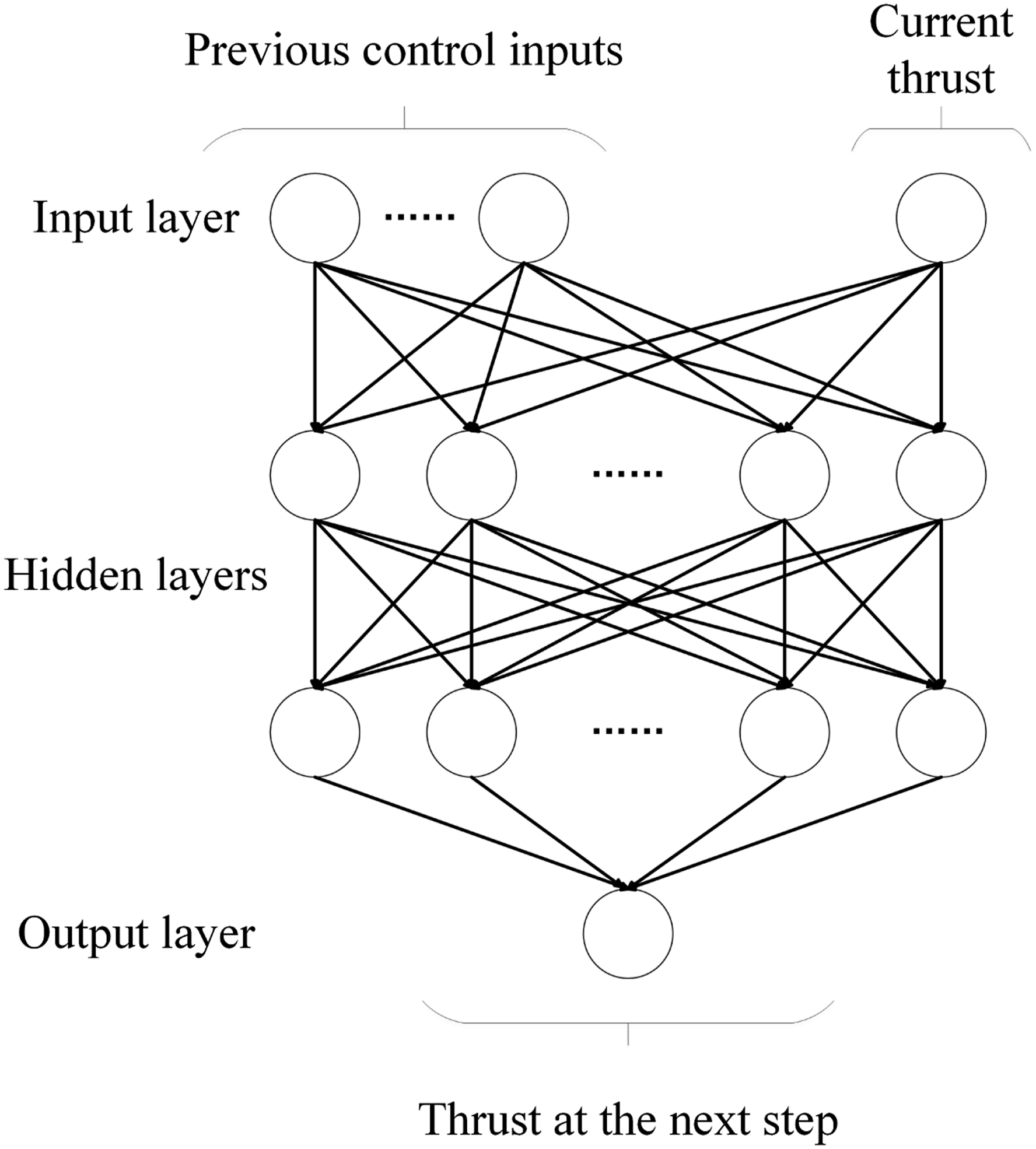
With the selected data samples, one can establish a data-driven model based on a Recurrent Neural Network (RNN), according to the experimental results of this study. As shown in Figure 3, the inputs of the NN-based model include the thrust at the current step and control inputs at the last Q steps, where Q ≤ P. Since a data sample only includes the last P control inputs, as shown in (1), to make the NN-based model trainable based on the collected data samples, the NN-based model can use at most the last P control inputs for its input, and thus Q ≤ P. Only the thrust at the current step is included in the inputs of an NN-based model, aiming to reduce the accumulated error of thrust predicted by the NN-based model. One can determine the value of Q according to the response of the motor-propeller system. The output of the NN-based model is the thrust at the next step. One should try RNNs of different sizes to balance the accuracy and time efficiency of the data-driven model used for rapid thrust control. Denote the NN-based model of a motor-propeller system as Structure of the neural-network-based motor-propeller model that predicts the thrust at the next time step from the current thrust and recent control inputs.
The parameters of the NN-based model should be updated by minimizing the loss function defined as
B. online thrust control based on model predictive control
To control the thrust of a motor-propeller system rapidly, the data-driven thrust control strategy combines an NN-based model with MPC to achieve a predictive thrust control strategy, and performs mode-switching
45
between the predictive thrust control strategy and the existing open-loop thrust control strategy. MPC is one of the most effective ways to achieve a generalization for a control strategy.
56
The flow diagram of the data-driven thrust control strategy is presented in Figure 4. To determine a control input to achieve a target thrust utilizing the data-driven model, the model predictive controller in this study is based on the random shooting technique,
57
because of the following reason. Flowchart of the online thrust control procedure integrating the neural-network-based predictive model, random-shooting MPC, and mode-switching mechanism.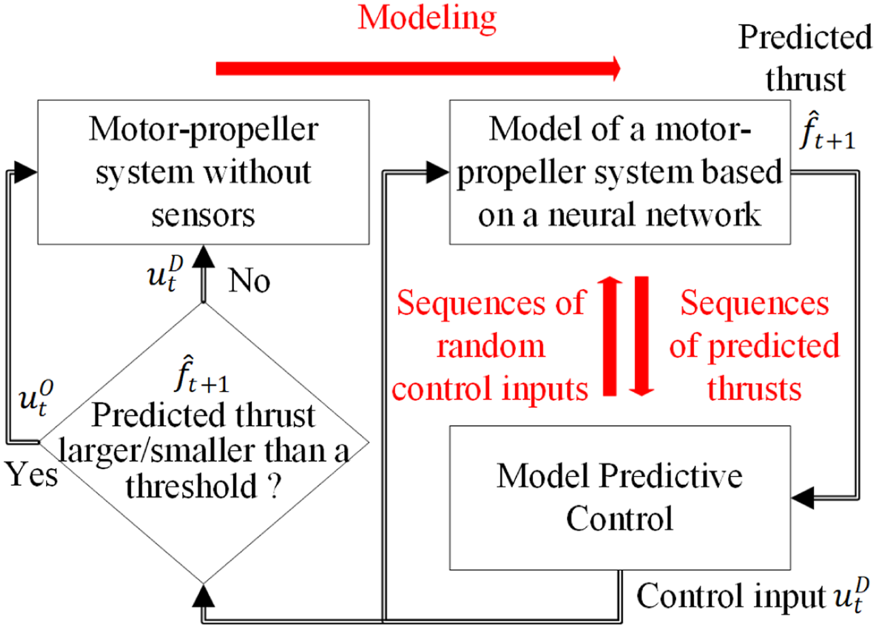
To design a random shooting-based MPC, one should properly adjust the number of sequences N and the number of the horizon of a sequence K to balance time consumption and control performance. According to an NN-based model and random shooting-based MPC combined framework, the model predictive controller predicts N sequences of thrusts by applying random control inputs, denoted as 
The cost J of N sequences should be calculated. The sequence with the minimum cost should be selected. The first control input (i.e.,
IV. Experiments
To evaluate the proposed data-driven thrust control strategy, this section compares the data-driven thrust control strategy to an open-loop thrust control strategy, a PD closed-loop thrust control strategy, an MPC closed-loop thrust control strategy, and an SMC closed-loop thrust control strategy based on a real motor-propeller system, as shown in Figure 1. The open-loop, PD, MPC, and SMC thrust control strategies are compared to the proposed data-driven thrust control strategy separately. It should be emphasized that the open-loop thrust control strategy doesn’t require sensors and is widely used in UAV control. 10 The open-loop thrust control strategy just applies the control input corresponding to a target thrust in steady-state. The PD, MPC, and SMC thrust control strategies require measuring the thrust generated by the motor-propeller system in real-time. The PD, MPC, and SMC thrust control strategies cannot be applied to motor-propeller systems without sensors to feedback real-time thrust. The PD, MPC, and SMC thrust control strategies are just baselines in this study and an external force sensor is used for the online measurement of the thrust generated by the motor-propeller system. It should be noticed that the data-driven thrust control strategy is developed for a general motor-propeller system, rather than motor-propeller systems for UAVs only, as mentioned in Remark 3. Specific challenges and factors encountered in the practical applications of UAVs are not comprehensively included in the experiments.
A. setups
The motor-propeller system used in the experiments consists of a Brushless Direct Current (BLDC) motor (T-MOTOR 2216 KV880) and a 10 × 4.5 propeller. BLDC motors are commonly used in UAVs and AUVs due to their low cost and lightweight. 59 UAVs and AUVs usually do not equip a sensor for every motor-propeller system because of the additional cost and weight. This study is motivated by the need to track target thrusts for UAV or AUV control. Thus, the experiment focuses on the BLDC motor and propeller of a UAV.
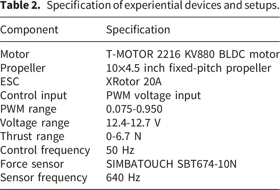
The control inputs of the motor-propeller system are voltage inputs represented by Pulse Width Modulation (PWM) values. PWM values are set to range from 0.075 to 0.950. The thrust outputs of the motor-propeller system range from 0.000 to 6.700 (unit: N). An Electronic Speed Controller (ESC) (XRotor 20A) transfers PWM values into voltage inputs applied to the motor-propeller system. To reduce the disturbance caused by battery voltage, experiments are conducted based on battery voltage ranging from 12.4 to 12.7 volts only. The thrust control strategies are implemented by a laptop with an i9-12900H CPU and a 16-gigabyte memory. The thrust control strategies run at a frequency of 50 Hz.
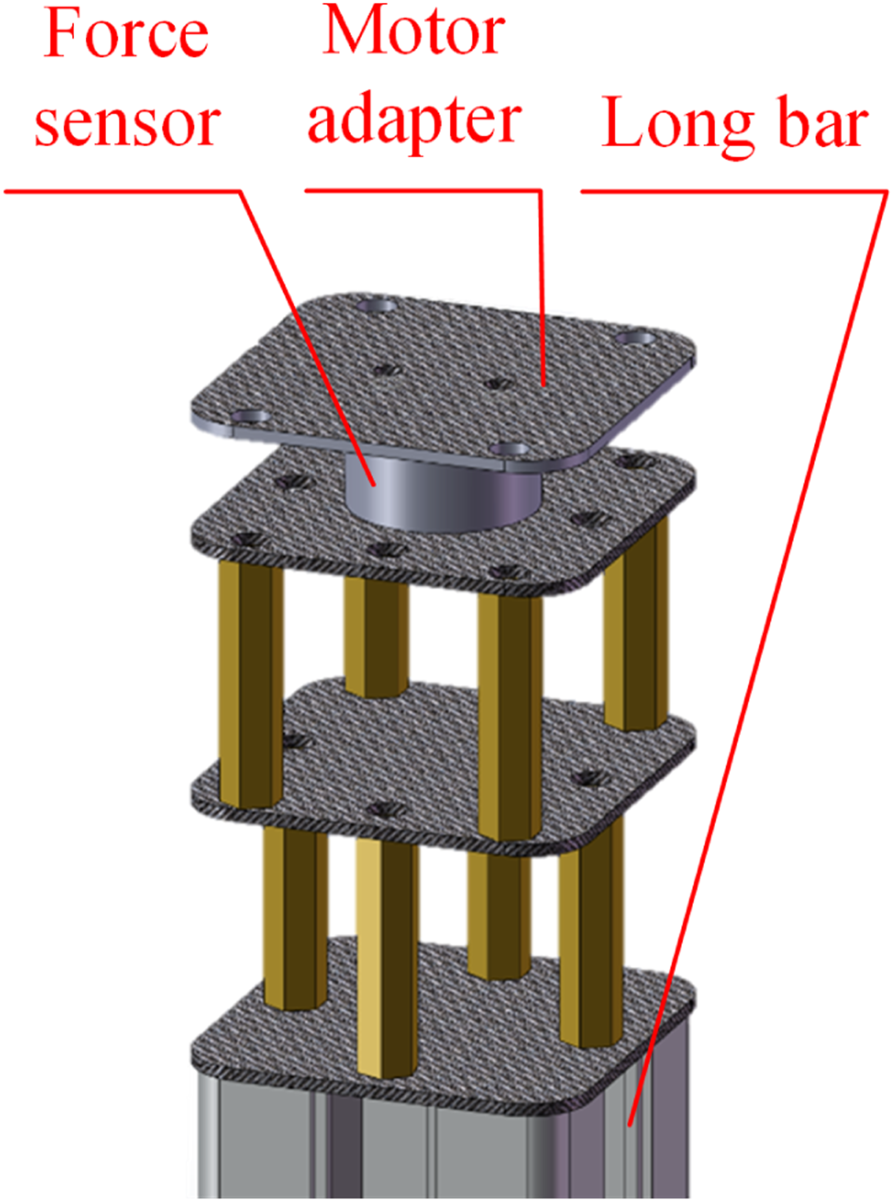
The aforementioned motor-propeller system and devices, as well as the test bench used in the experiments, are shown in Figure 5. The detailed architecture of the test bench is shown in Figure 6. The motor-propeller system is mounted on top of the test bench. The test bench is mounted on top of a long bar, allowing airflow to flow downward freely. The thrust of the motor-propeller system is measured by a force sensor (SIMBATOUCH SBT674-10N). The force sensor has a frequency of 640 Hz. The force sensor is mounted immediately underneath the motor-propeller system, as shown in Figure 6, to measure the magnitude of thrust. The force sensor is used 1) to collect data samples on a motor-propeller system for the data-driven thrust control strategy; 2) to evaluate the thrust tracking performance of the data-driven thrust control strategy, the widely used open-loop thrust control strategy in UAV control, and the PD, MPC, and SMC thrust control strategies; and 3) to measure and feedback the thrust of the motor-propeller system for the PD, MPC, and SMC thrust control strategies that require a sensor. The force sensor with a frequency of 640 Hz can timely measure the true value of thrust for control strategies or data acquisition. For data acquisition and thrust control, the data from the force sensor is used at a frequency of 50 Hz, actually. The specification of experiential devices and setups is listed in Table 2. Experimental platform used for thrust control evaluation, including the motor-propeller system, ESC, force sensor, laptop-based controller, power supply, and custom thrust measurement test bench. Detailed architecture of the thrust measurement and control test bench, illustrating the mechanical mounting structure, force sensor placement, airflow direction, signal acquisition path, ESC-driven motor actuation, and communication between the controller and sensing devices. Specification of experiential devices and setups.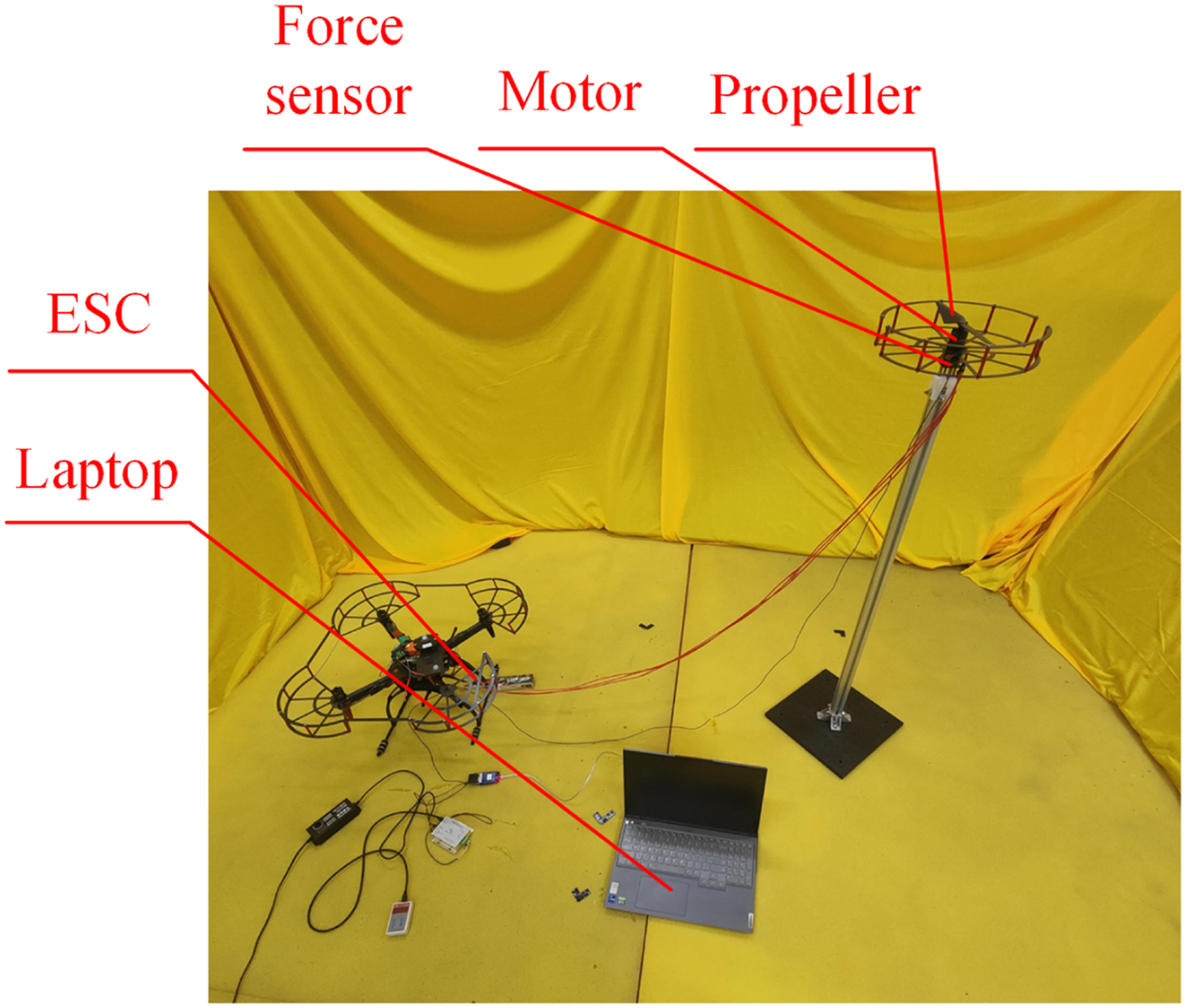
B. data generation and selection
In this study, three types of voltage inputs are applied to generate data samples for the data-driven thrust control strategy, as shown in Figure 7. It should be noted that one can also use voltage inputs that differ from those shown in Figure 7 to generate data samples. The first type of voltage input is a series of constant signals that change every second. The voltage input decreases from 0.95 to 0.075 and then increases to 0.95 gradually. The second type of voltage input consists of nine sets of Gaussian distribution signals. The means of the sets are 0.16, 0.25, 0.34, 0.43, 0.52, 0.61, 0.70, 0.79, and 0.88, respectively. The variance of the sets is 0.175. The third type of voltage input consists of 40 sets of square-wave signals that have a frequency of 1.25 Hz. The voltage input decreases from 0.95 to 0.075 and then increases to 0.95 gradually. The thrust outputs generated by the voltage inputs are presented in Figure 8. Voltage input signals used for data generation, including constant-step, Gaussian-distributed, and square-wave excitation signals. Thrust responses generated by the voltage input sequences used for collecting training and validation data samples.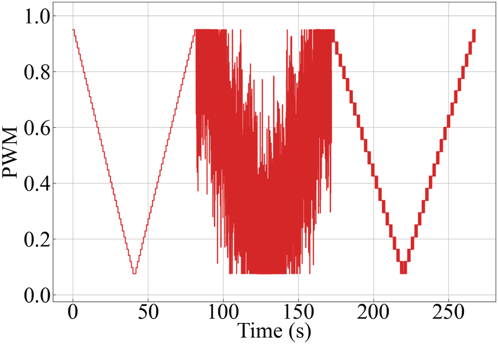
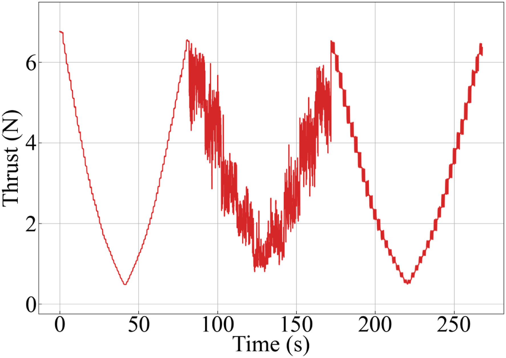
According to the response delay of the motor-propeller system, the voltage inputs are shifted forward by two steps for data alignment. A data sample is set to include the thrust and control input of the last six steps and the thrust at the next step. A data sample, denoted as (

The norm represents the distance between a data sample and the origin in a six-dimensional space and reflects the sum of six thrusts of a data sample in general. For a data sample (
According to the KS method, 6,250 data samples are selected from the 13,392 data samples, as shown in Figure 9. Figure 9 shows that selected data samples are more uniformly distributed compared to the collected data samples and thus are beneficial for modeling.
27
Comparison between the distributions of collected data samples and representative samples selected using the Kennard-Stone method.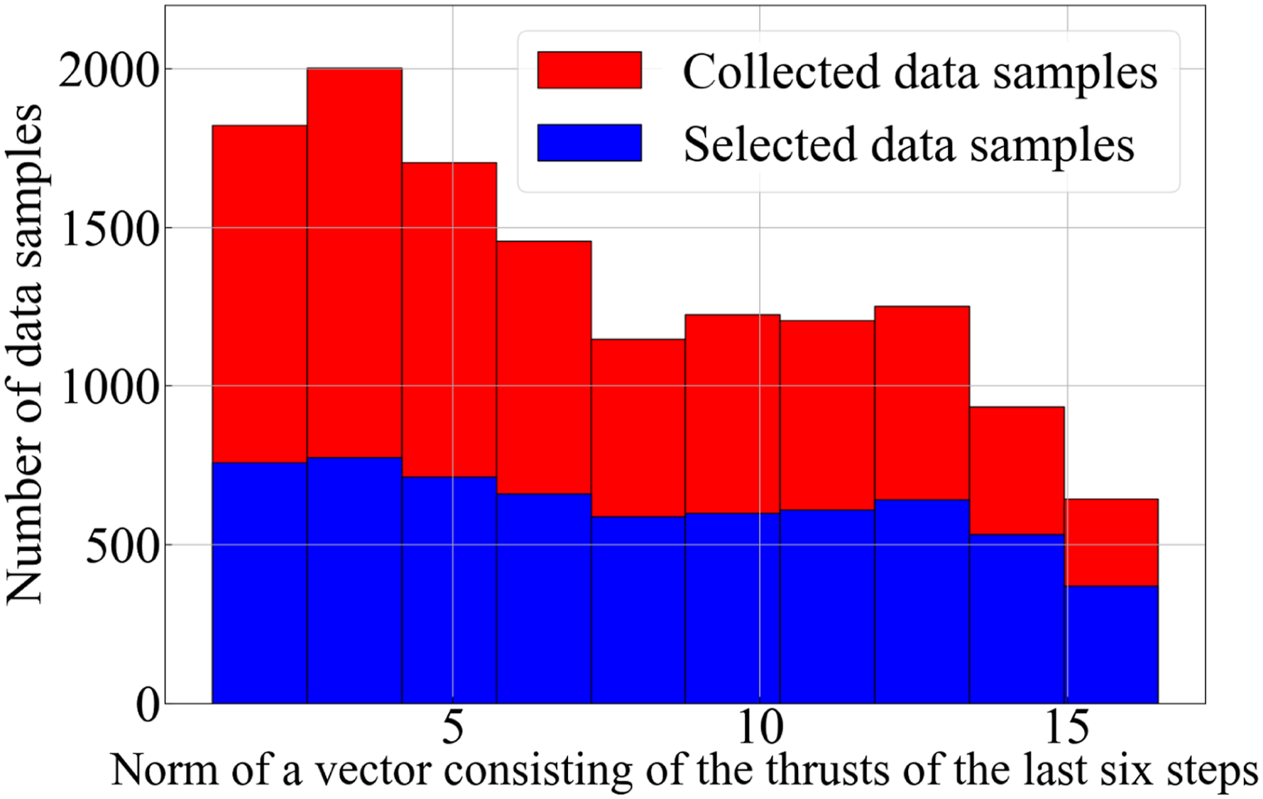
C. modeling based on different neural networks
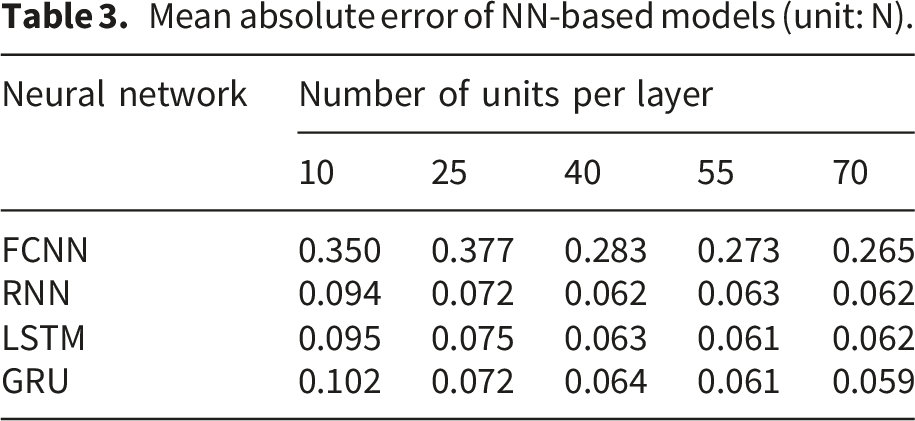
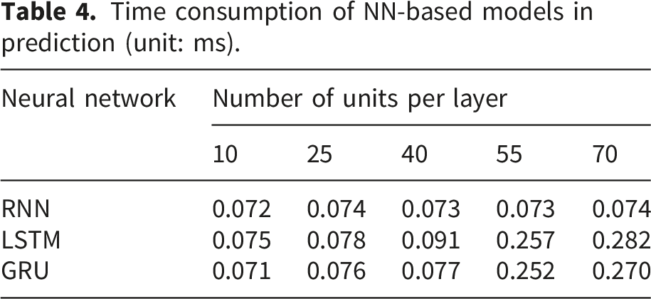
According to the proposed data-driven thrust control strategy, one should establish an NN-based model of the motor-propeller system based on the selected data samples. Based on an analysis of the response of the motor-propeller system used in experiments, an NN-based model is designed to predict the thrust of the motor-propeller system according to the thrust of the current step and the voltage input of the last four steps. Considering that the NN-based model takes sequential voltage inputs, this study applies different neural networks, including Fully Connected Neural Networks (FCNNs), RNNs, Long Short-Term Memory (LSTM), and Gate Recurrent Unit (GRU) to achieve NN-based models and then selects an NN-based model with a balance of accuracy and time efficiency. The input of an NN-based model consists of the thrust of the current step and the voltage input of the last four steps. The output of an NN-based model is the thrust of the next step. 20 percent of the selected data samples (i.e.,1,250 data samples) are used for validation. The rest 80 percent of the selected data samples (i.e.,5,000 data samples) are used for training.
According to the literature, determining the optimal size of a neural network still has no clear guideline.
60
Thus, FCNN, RNN, LSTM, and GRU with five different sizes are used to establish NN-based models. The FCNN, RNN, LSTM, and GRU are set to have two hidden layers. The numbers of units in every hidden layer of FCNN, RNN, LSTM, and GRU have been set to 10, 25, 40, 55, and 70 to achieve the five different sizes. This study set dropout = 0.2, iteration epochs = 350, batch size = 1024, and learning rate = 0.001. The Adam optimizer is used for training. The loss of the RNN-based model with two hidden layers, each of which includes 40 units, in training and validation is shown in Figure 10. Training and validation loss curves of the RNN-based motor-propeller model with 40 hidden units per layer during offline learning.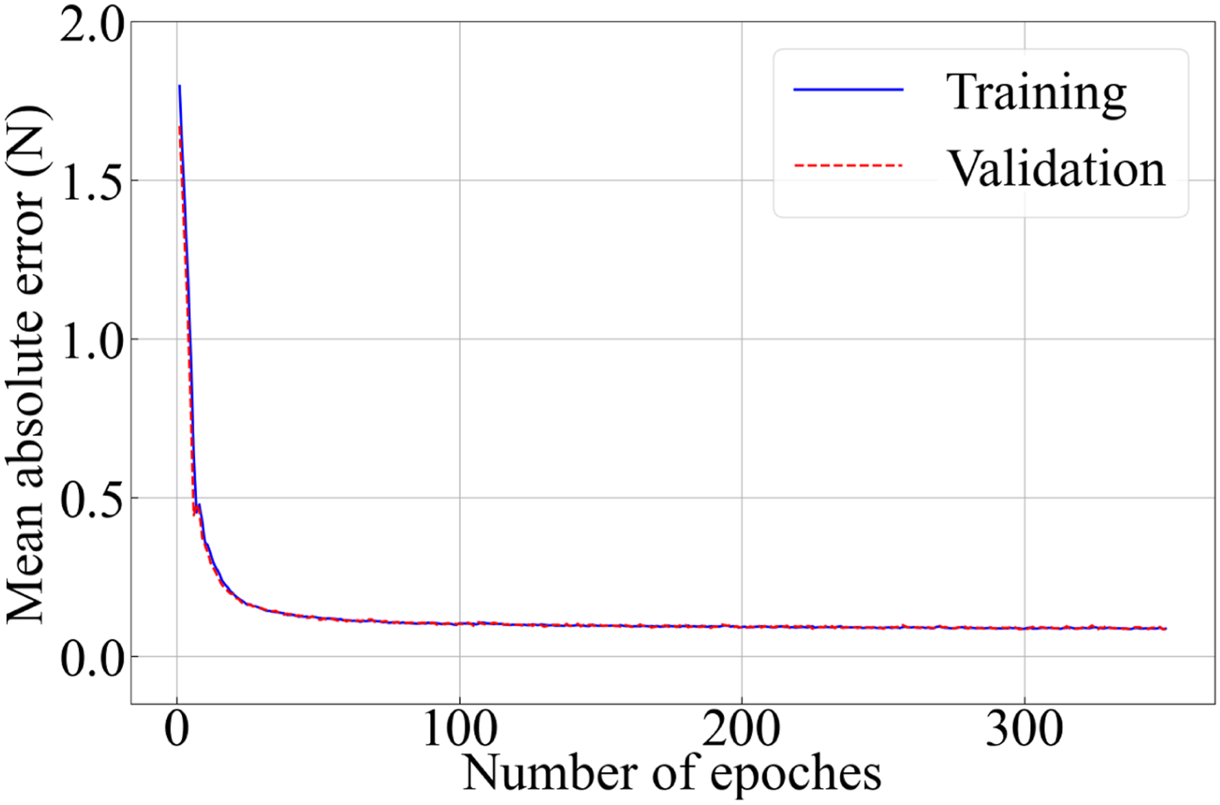
Mean absolute error of NN-based models (unit: N).
Time consumption of NN-based models in prediction (unit: ms).
D. implementation of thrust control strategies
To verify the effectiveness of the data-driven thrust control strategy in rapid thrust control of a motor-propeller system, different control strategies are applied to control the thrust of the motor-propeller system, including the data-driven thrust control strategy (ours), a well-turned PD thrust control strategy (baseline), an open-loop thrust control strategy (baseline), an MPC thrust control strategy (baseline), and an SMC thrust control strategy (baseline). The open-loop thrust control strategy is a widely used conventional counterpart of the data-driven thrust control strategy. The PD thrust control strategy, rather than a PID thrust control strategy, is used because the responsiveness, rather than the steady-state error, of the thrust of the motor-propeller system is a priority in the thrust control. It should be noticed that the PD, MPC, and SMC thrust control strategies are just baselines. The PD, MPC, and SMC thrust control strategies cannot be applied to motor-propeller systems without sensors available for real-time thrust measurement. The PID-based control strategies are the most widely used control strategies in motor control in practice. 61 The data-driven thrust control strategy is compared to the PID thrust control strategy, aiming to show the performance of the data-driven thrust control strategy with respect to that of the most widely used control strategy. Then, the value of the data-driven thrust control strategy can be reflected. It should be pointed out that the data-driven thrust control strategy without requiring sensors is not assumed to perform better than state-of-the-art advanced control strategies requiring sensors.
Polynomial fitting result representing the steady-state relationship between PWM voltage input and generated thrust of the motor-propeller system.
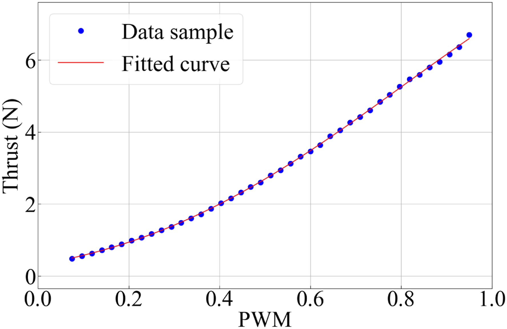
The coefficients are p2= 4.048, p1= 3.045, and p0= 0.171.



The MPC thrust control strategy determines a control input to achieve the target angular velocity ω* corresponding to the target thrust, based on a cost function that can be expressed as

Based on the sliding mode surface, the control input is defined as
E. thrust tracking tests
The motor-propeller system is controlled by the data-driven thrust control strategy and the baseline thrust control strategies to track target thrust trajectories, aiming to evaluate the effectiveness of the data-driven thrust control strategy in improving the responsiveness of the thrust control of a motor-propeller system from the widely used open-loop thrust control strategy and show its thrust tracking performance. Two case studies are included in thrust tracking tests. In the two case studies, the target thrust trajectories are a square-wave trajectory with a frequency of 0.5 Hz and a trajectory that changes randomly every 0.4 seconds, respectively. Target thrusts are set to range from 3.3 N to 5.3 N, according to the thrust range mostly used by a UAV, for which the motor-propeller system is applicable, in hovering and cruising.
The results of thrust control strategies in tracking the square-wave target thrust trajectory with a frequency of 0.5 Hz are shown in Figure 12. To track the square-wave target thrust trajectory, the coefficients of the PD thrust control strategy are tuned to be K
P
= 0.04, and K
D
= 0.004. The target thrust trajectory is represented by a black dash line. The actual thrusts achieved by the data-driven thrust control strategy, the PD thrust control strategy, and the open-loop thrust control strategy, the MPC thrust control strategy, and the SMC thrust control strategy are represented by a blue solid line, a magenta dot dash line, a red dot line, a green line with squares, and a orange line with triangles, respectively. The voltage inputs are presented in Figure 13. The Mean Absolute Error (MAE), average rise time, and average fall time are used to represent the tracking error and transient response of the thrust control strategies. The rise time and fall time are the time required for the response to start from 10 % to 90 % of the target value larger or smaller than the current value, respectively.63,64 The MAE, average rise time, and average fall time achieved by the thrust control strategies are shown in Table 5. The mean MAE between the thrust achieved by the data-driven thrust control strategy and the target thrust is 0.271 (unit: N). The mean MAE between the thrust achieved by the PD thrust control strategy, open-loop thrust control strategy, MPC thrust control strategy, and SMC thrust control strategy, and the target thrust is 0.265, 0.314, 0.456, and 0.394 (unit: N), respectively. The rise time of thrust achieved by the data-driven thrust control strategy, the PD thrust control strategy, the open-loop thrust control strategy, and the SMC thrust control strategy are 0.037, 0.057, 0.141, and 0.055 (unit: seconds), respectively. The fall time of the thrust achieved by the data-driven thrust control strategy, the PD thrust control strategy, the open-loop thrust control strategy, and the SMC thrust control strategy are 0.058, 0.079, 0.122, and 0.090 (unit: seconds), respectively. The rise time and fall time of the MPC thrust control strategy are not applicable because the strategy sometimes fails to achieve 90 % of the target value larger or smaller than the current value. One can see that, in generating a square-wave thrust with a frequency of 0.5 Hz, through implementing proper aggressive voltage inputs (i.e.,overshoots shown in Figure 13), the data-driven thrust control strategy without requiring sensors can achieve accuracy, average rise time, and average fall time better than the open-loop thrust control strategy and comparable to the PD, MPC, and SMC thrust control strategies requiring a force sensor. Namely, considering strategies without requiring sensors, the data-driven thrust control strategy performs better than the widely used open-loop thrust control strategy. Compared to strategies requiring sensors, the data-driven thrust control strategy without requiring sensors can achieve comparable performance in response (a major objective of this study) and accuracy. Then, the superiority of the data-driven thrust control strategy can be demonstrated. Comparison of thrust tracking performance for different control strategies when tracking a 0.5 Hz square-wave target thrust trajectory. Voltage control inputs generated by different thrust control strategies during tracking of the 0.5 Hz square-wave target thrust trajectory. MAE, rise time, and fall time of thrust control strategies in tracking a square-wave target thrust trajectory.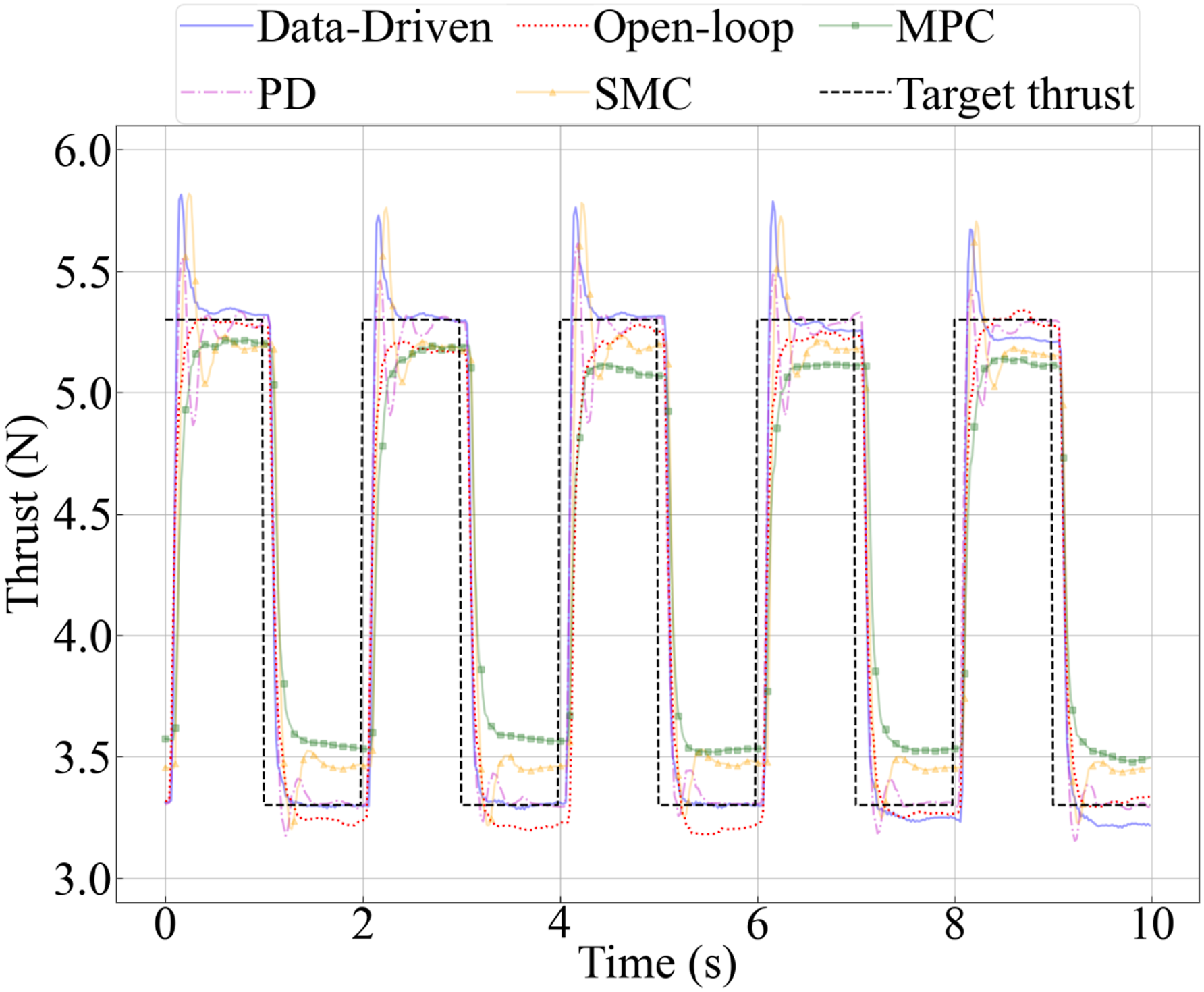
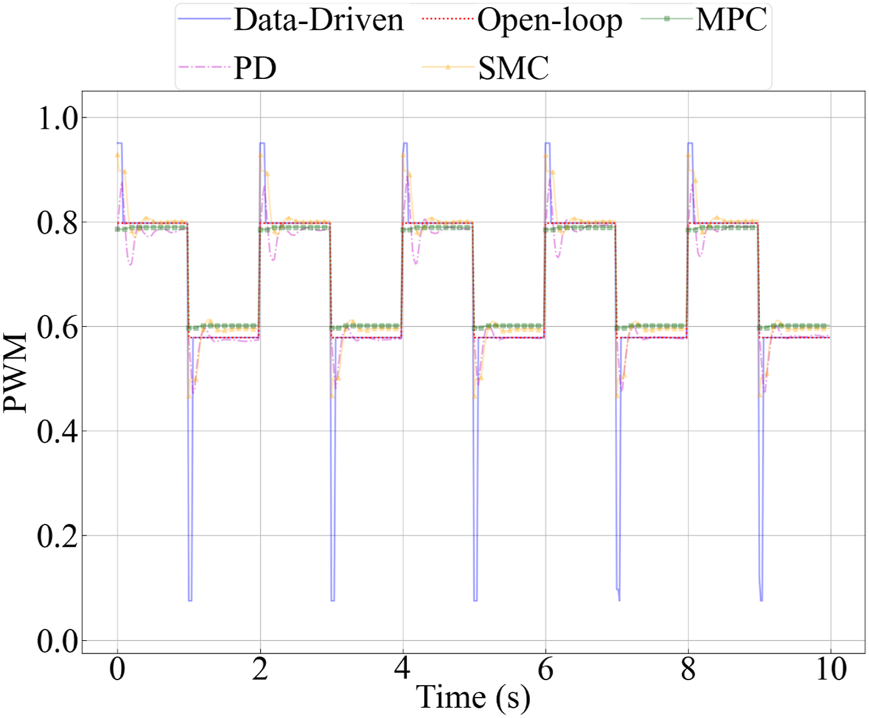
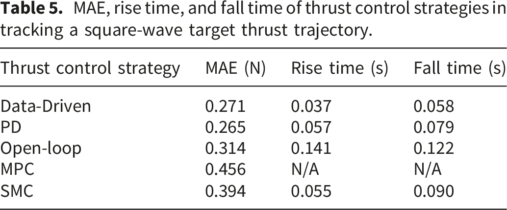
Compared with the conventional open-loop strategy, the proposed data-driven strategy reduced the rise time from 0.141 s to 0.037 s in the square-wave tracking task, corresponding to a 73.8% improvement. Similarly, the fall time was reduced by 52.5%. These improvements demonstrate that the proposed predictive control mechanism can effectively compensate for the dynamic delay caused by motor-propeller inertia.
The results of thrust control strategies in tracking the target thrust trajectory that changes randomly every 0.4 seconds are shown in Figure 14. To track the square-wave target thrust trajectory, the coefficients of the PD thrust control strategy are tuned to be K
P
= 0.05, and K
D
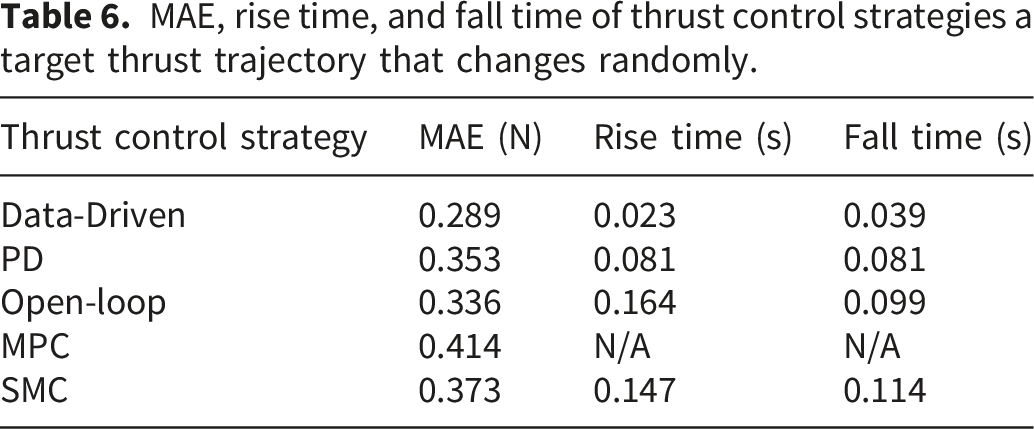
= 0.003. The target thrust trajectory is represented by a black dash line. The actual thrusts achieved by the data-driven thrust control strategy, the PD thrust control strategy, the open-loop thrust control strategy, the MPC thrust control strategy, and the SMC thrust control strategy are represented by a blue solid line, a magenta dot dash line, a red dot line, a green line with squares, and a orange line with triangles, respectively. The voltage inputs are presented in Figure 15. The MAE, average rise time, and average fall time achieved by the thrust control strategies are shown in Table 6. The mean MAE between the thrust achieved by the data-driven thrust control strategy and the target thrust is 0.289 (unit: N). The mean MAE between the thrust achieved by the PD thrust control strategy, open-loop thrust control strategy, MPC thrust control strategy, SMC thrust control strategy, and the target thrust is 0.353, 0.336, 0.414, and 0.373 (unit: N), respectively. The rise time of thrust achieved by the data-driven thrust control strategy, the PD thrust control strategy, the open-loop thrust control strategy, and the SMC thrust control strategy are 0.023, 0.081, 0.164, and 0.147 (unit: seconds), respectively. The fall time of the thrust achieved by the data-driven thrust control strategy, the PD thrust control strategy, the open-loop thrust control strategy, the MPC thrust control strategy, and the SMC thrust control strategy are 0.039, 0.081, 0.099, and 0.114 (unit: seconds), respectively. The rise time and fall time of the MPC thrust control strategy are not applicable because the strategy sometimes fails to achieve 90 % of the target value larger or smaller than the current value. It is shown that even if a force sensor is not available for online thrust measurement, through implementing proper aggressive voltage inputs (i.e.,overshoots shown in Figure 15), the data-driven thrust control strategy can achieve accuracy, average rise time, and average fall time better than the open-loop thrust control strategy and comparable to the PD, MPC, and SMC thrust control strategies requiring a force sensor, in generating the thrust that changes randomly every 0.4 seconds. Namely, considering strategies without requiring sensors, the data-driven thrust control strategy performs better than the widely used open-loop thrust control strategy. Compared to strategies requiring sensors, the data-driven thrust control strategy without requiring sensors can achieve comparable performance in response (a major objective of this study) and accuracy. Then, the superiority of the data-driven thrust control strategy can be demonstrated in this case also. Comparison of thrust tracking performance for different control strategies when tracking a randomly varying target thrust trajectory updated every 0.4 seconds. Voltage control inputs generated by different thrust control strategies during tracking of the randomly varying target thrust trajectory. MAE, rise time, and fall time of thrust control strategies a target thrust trajectory that changes randomly.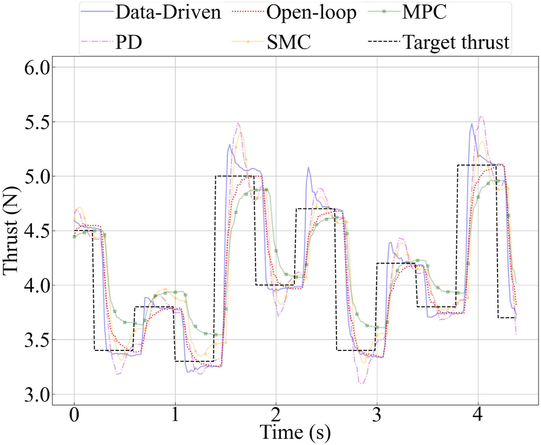
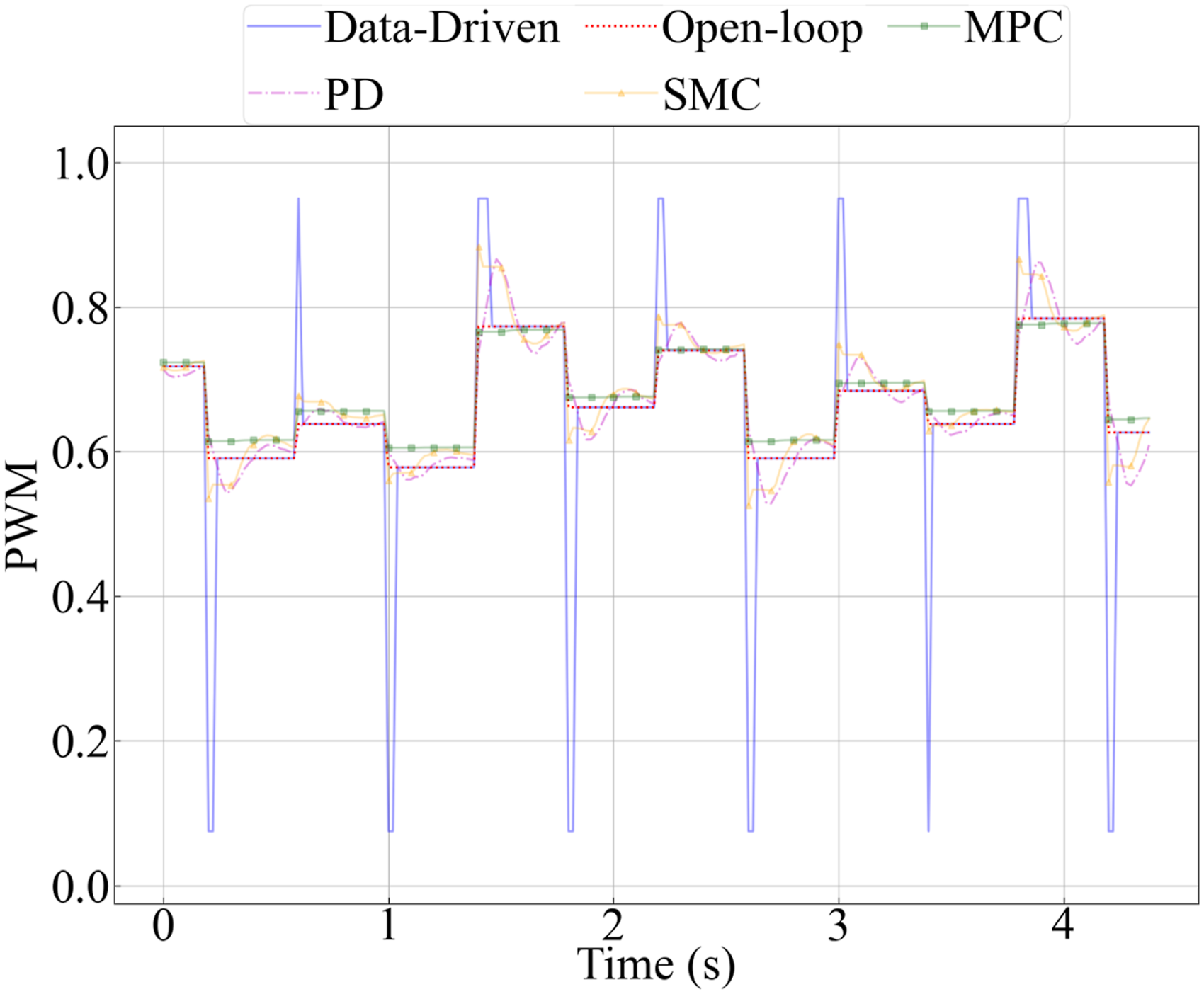
Although the PD controller achieved slightly lower MAE in one case, it relied on real-time thrust measurements from an external force sensor. In contrast, the proposed method achieved comparable tracking performance without requiring any online sensing, demonstrating its practical value for lightweight and low-cost UAV systems.
F. embedded system deployment
The data-driven thrust control strategy is deployed to an embedded system, considering that a UAV or AUV equips an embedded system, rather than a laptop. As shown in Figure 16, the embedded system used in this study is a Jetson Nano, which has been used in our previous study of a UAV.
65
For the embedded system, this study also combines the RNN-based model with 40-unit layers and a random shooting-based MPC controller to establish the data-driven thrust control strategy. Different from the random shooting-based MPC controller deployed to the laptop, the predicted horizon is set to three steps (i.e.,K= 3) and the number of control sequences of thrusts is 500 (i.e.,N= 500) for the random shooting-based MPC controller deployed to the embedded system due to its computational capability. The results of the data-driven thrust control strategy deployed to a laptop and the strategy deployed to an embedded system in tracking the square-wave target thrust trajectory with a frequency of 0.5 Hz are shown in Figure 17. The voltage inputs are presented in Figure 18. Embedded-system-based experimental setup using a Jetson Nano for real-time implementation of the proposed data-driven thrust control strategy, including the motor-propeller system, ESC, power supply, and thrust measurement hardware. Comparison of thrust tracking performance between laptop-based and embedded-system-based implementations of the proposed strategy for a 0.5 Hz square-wave target thrust trajectory. Voltage control inputs generated by the laptop-based and embedded-system-based implementations during square-wave thrust trajectory tracking.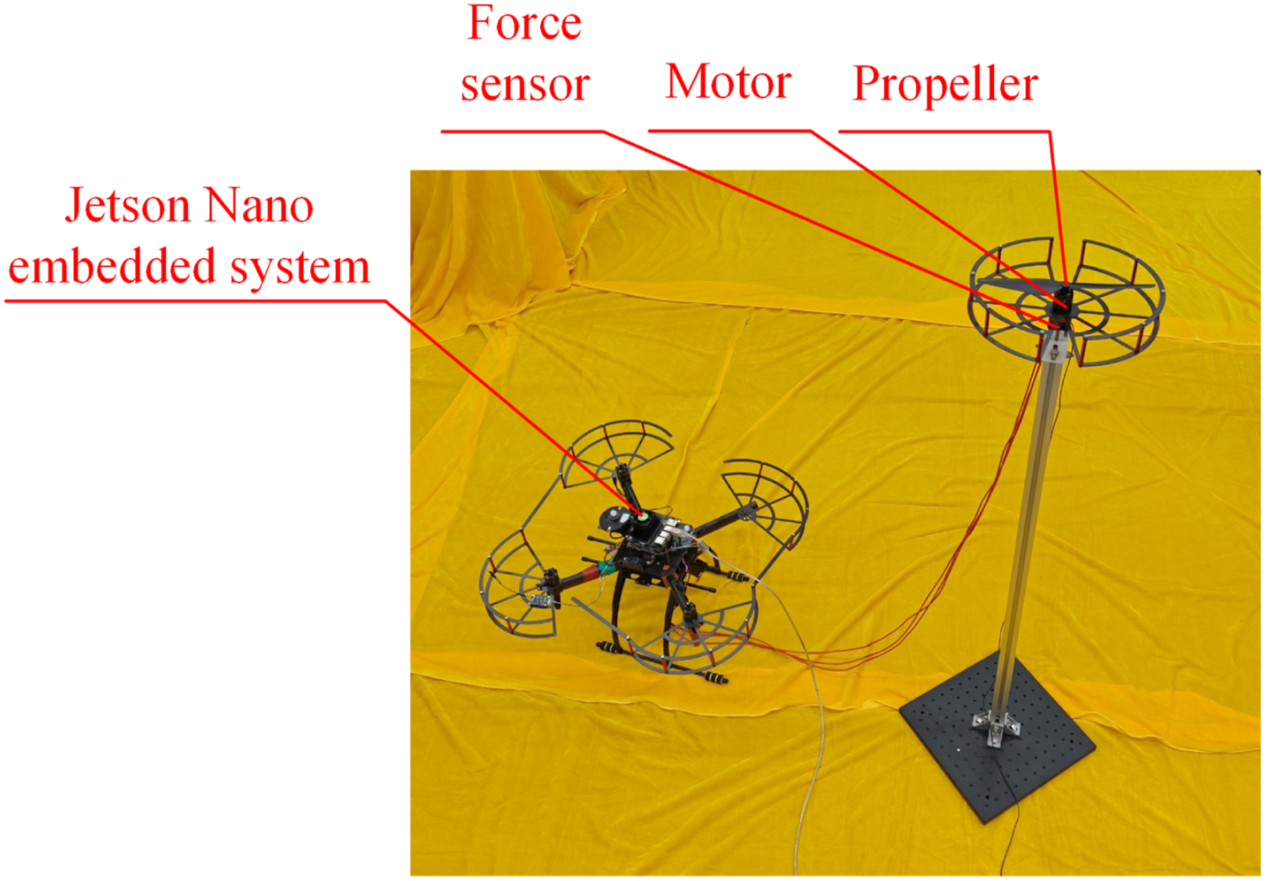
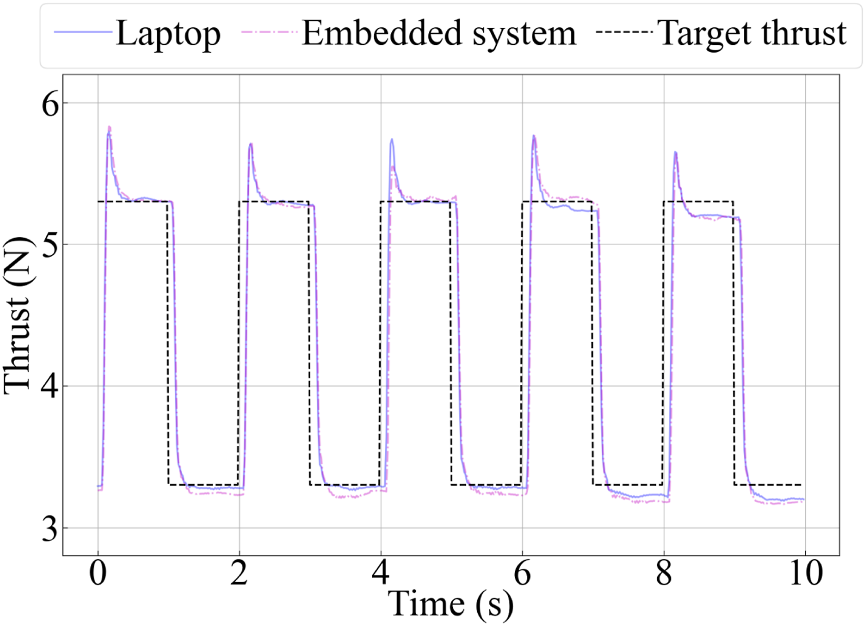
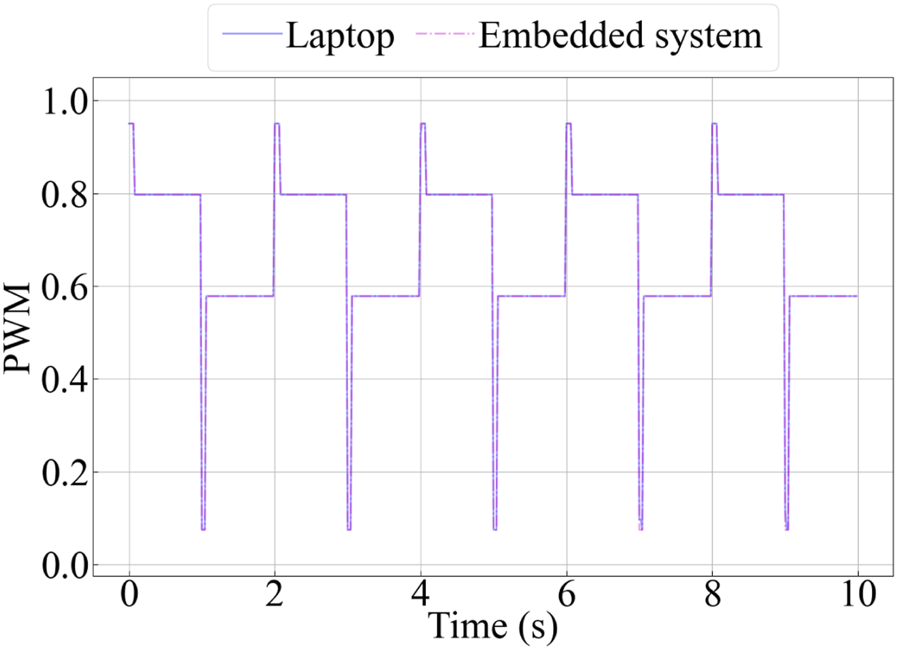
According to Figures 17 and 18, the data-driven thrust control strategy deployed to a laptop and the strategy deployed to an embedded system achieve almost the same performance in thrust tracking and voltage input determination, even if the predicted horizon and the number of control sequences have been reduced. According to the understanding of the authors, to track a step change of the target thrust quickly, the maximum or the minimum voltage input should be applied in the next few steps. Then, the voltage input is determined by the open-loop thrust control strategy if the predicted thrust is larger than or smaller than a threshold. In this case, the accuracy of the NN-based model is more important than the predicted horizon and the number of control sequences. This suggested that the data-driven thrust control strategy deployed to an embedded system can further reduce the predicted horizon and the number of control sequences to adapt to the limited computational capability, if it is necessary.
V. Conclusion
This paper proposed a data-driven sensorless rapid thrust control strategy for motor-propeller systems without requiring online force sensors or encoders. Different from conventional open-loop thrust control methods that apply a fixed steady-state control input, the proposed strategy dynamically adjusts control inputs according to predicted thrust evolution, thereby improving transient response and thrust tracking accuracy. A neural-network-based model was established offline to predict future thrust from recent control inputs and estimated thrust states, and the learned model was integrated with a random-shooting MPC framework and a mode-switching mechanism to achieve practical sensorless rapid thrust control.
Experimental studies based on a real BLDC motor-propeller system demonstrated the effectiveness of the proposed approach. Compared with the widely used open-loop thrust control strategy, the proposed method significantly improved both thrust tracking accuracy and transient response. For square-wave thrust tracking, the proposed strategy reduced rise time from 0.141 s to 0.037 s and fall time from 0.122 s to 0.058 s while lowering the MAE from 0.314 N to 0.271 N. For randomly varying thrust trajectories, the proposed strategy achieved a rise time of 0.023 s and a fall time of 0.039 s, substantially outperforming the open-loop method and achieving lower tracking errors than PD, MPC, and SMC baselines in this scenario. These results demonstrate that the proposed strategy can achieve response characteristics comparable to or better than several sensor-based controllers while operating completely without online sensing.
The study also demonstrated that recurrent neural networks provide a better balance between prediction accuracy and computational efficiency than FCNN, LSTM, and GRU models for motor-propeller system modeling. Furthermore, deployment on a Jetson Nano embedded platform verified the practicality of the proposed approach for real-time robotic applications with limited onboard computational resources.
Overall, the proposed strategy provides a lightweight, low-cost, and sensorless solution for improving thrust responsiveness in robotic propulsion systems. The framework is applicable not only to UAV propulsion systems but also to other robotic platforms employing motor-propeller actuation, including marine vehicles. Future work will focus on reducing the computational cost of predictive control, improving model generalization under varying aerodynamic conditions, and incorporating airflow disturbances and multi-propeller interactions into the data-driven modeling framework.
Footnotes
Acknowledgment
The authors would like to thank the editors and reviewers for their valuable comments and suggestions. The authors would also like to thank Chengmin Bian, Yi Wang, and Yuanjie Yu for his dedication to this paper.

Consent to participate
This article does not contain any studies with human or animal participants.
Funding
The authors disclosed receipt of the following financial support for the research, authorship, and/or publication of this article: This work is supported by the National Natural Science Foundation of China (NSFC) through grant 52405010 and by the Shenzhen Science and Technology Program under grants GXWD20231130150349002, JCYJ20220531095605012, KJZD20230923115210021, and 29853MKCJ202300205.
Declaration of conflicting interests
The authors declared the following potential conflicts of interest with respect to the research, authorship, and/or publication of this article: I hereby disclose that I am a current member of the editorial board of the International Journal of Advanced Robotic Systems. However, I affirm that this affiliation has not influenced the objectivity, analysis, or conclusions presented in this work. All editorial processes for this submission, including peer review and decision-making, were managed in strict accordance with the journal’s ethical guidelines to ensure impartiality.
Data Availability Statement
Any data gathered and reported in this study are available from the corresponding authors upon reasonable request.