
Abstract
This study numerically investigates the thermal performance of simplified multilayer roof assemblies for hot-climate applications. Six roof configurations were considered by combining aluminum or galvalume as the exposed upper reflective layer with polystyrene, polyethylene, or polyisocyanurate as the concealed middle layer and a rigid bottom substrate. A quasi-steady thermal analysis was performed in ANSYS Workbench 2020 R1 by applying time-varying solar-radiation and ambient temperature inputs as a sequence of independent quasi-steady-state calculations. The numerical model was checked using mesh-independence analysis and benchmarked against published experimental data. The results indicate that aluminum-based assemblies produced lower heat-flux transfer than galvalume-based assemblies due to the higher solar reflectance of the exposed aluminum layer. Among the tested configurations, combination-2, consisting of aluminum, polyethylene, and the rigid substrate, produced the lowest average heat flux among the aluminum-based cases, approximately 18 W/m2. Combination-5, consisting of galvalume, polyethylene, and the rigid substrate, showed the lowest average heat flux among the galvalume-based cases, approximately 19 W/m2. Since polyethylene was used as a concealed middle layer, its solar reflectance was not applied as an exposed-surface boundary condition; therefore, the observed performance should be interpreted in terms of the assigned material properties, layer arrangement, and simplified quasi-steady modeling assumptions. The findings provide a comparative assessment of selected multilayer roof assemblies and highlight the importance of exposed-surface reflectance and layer configuration in reducing roof heat gain in hot climates.
Keywords
Introduction
Bangladesh has a tropical monsoon climate, characterized by high temperature, humidity, and strong seasonal variation in solar radiation (Mondal et al., 2020; Shahid, 2010). In hot and humid regions, roof heat gain is one of the major contributors to indoor thermal discomfort and increased cooling demand, because the roof is directly exposed to solar radiation for long periods during the day. When incident solar radiation reaches the roof surface, part of the radiation is reflected, while the remaining portion is absorbed and transferred through the roof assembly by conduction, convection, and radiation. Several passive roof-cooling strategies have been used to reduce heat transfer through building envelopes, including conventional insulation, cool roofs, reflective coatings, and radiant-barrier systems (Arumugam et al., 2015; Ashhar and Lim, 2020; Krüger et al., 2018; Lee et al., 2016). A radiant barrier generally consists of a low-emissivity reflective surface installed adjacent to an air space, where it reduces radiative heat exchange across the cavity. In simplified multilayer roof assemblies, reflective outer layers and insulating mid-layers can also reduce absorbed solar heat and conductive heat transfer through the roof. The effectiveness of these systems depends on material properties, layer arrangement, surface reflectance/emissivity, thermal conductivity, roof geometry, and climatic boundary conditions.
Previous studies have shown that radiant barriers, reflective insulation, cool roofs, and multilayer roof assemblies can reduce roof heat gain under hot-climate conditions. Lee et al. (2016) reviewed reflective thermal insulation systems and reported that radiant barriers can reduce roof heat flux, especially when radiative heat transfer and ventilation effects are properly considered. Medina (2000) investigated the effectiveness of radiant barriers in residential settings through experiments and computer simulations. Two identical houses were compared in central Texas, USA, varying in attic insulation levels. Hu et al. (2021) presented a new solution for addressing energy needs in areas with varying temperatures. The authors introduced a rotatable bifacial solar module that can alternate between heating through solar and cooling modes of a radiative cooler. Yew et al. (2018) investigated the effectiveness of active and passive cool roof systems in reducing heat transmission into industrial building attics through metal deck roofing in Malaysia. Chang et al. (2008) evaluated a double-roof prototype incorporating a radiant-barrier system and showed that roof configuration plays an important role in reducing solar heat gain. Kumar et al. (2021) studied double-skin polystyrene–aluminum reflector roofs in arid climates and found that the air gap between layers significantly affects passive cooling performance. Karava et al. (2011) examined the forced convection transfer of heat on the inclined roof in a low-height building, specifically for building-integrated Photovoltaic/Thermal (PV/T) systems. Alshayji and Ebrahim (2020) numerically simulated radiant-barrier systems in inclined roofs, showing the relevance of computational modeling for roof heat-transfer analysis. Agugiaro et al. (2011) used common weather data to accurately estimate solar potential. Sunshine-based models were the most successful, whereas cloud cover models were the least accurate. Pisello et al. (2013) conducted a study in Rome, investigating the effects of a cool roof system on an office building. Testa and Krarti (2017) showed that cool roofs are ideal for the summer, but not for the winter. Switchable roofs might address this issue by reflecting sunlight in the summer and absorbing it in the winter, potentially conserving electricity year-round. Shi et al. (2024) demonstrated the effective use of a radiant barrier, while Akhter et al. (2024, 2025) developed the insulating materials that will be effectively used in building wall inside insulation and for roof insulation as a radiant barrier. Ye et al. (2024) systematically analyzed the radiant cooling panel. Acharya et al. (2024) developed a model to evaluate the thermal protective performance of fire-retardant clothing exposed to flame and radiant heat. They found that fabric optical properties, skin conductivity, and air gap width significantly affect protective performance and burn injury durations. Elfadeel et al. (2024) developed a novel integrated radiant wall system combining a solar collector and radiant heating terminal for sustainable heating. The system achieved heating capacities up to 60.82 W/m2 and demonstrated reduced thermal losses with a payback period of 5.53 years. Xin et al. (2024) conducted a numerical investigation to assess the effect of fabric deformation on heat transfer in thermal protective clothing. Their findings revealed that both stretching and compression of the fabric increase heat transfer to the skin, with compression deformation resulting in more significant burns, particularly in the arms and legs. Su et al. (2024) analyzed the possible risk of moisture condensation on the radiant barrier. Gu et al. (2024) showed an analysis of different conductive materials and materials of different transmittance. Pk et al. (2024) demonstrated the influences of thermal radiation and variable porosity on a time-dependent magnetoconvective heat-mass transfer past a vertical porous sheet, while Rui et al. (2024) conducted an experiment on a multilayer protective radiant barrier. Rajput et al. (2024) showed an analysis on fire retardant fabric materials and different exposure conditions. László (2024) demonstrated the effects of radiant setting on poly materials. Koutsakis and Clarke (2024) explored the effects of absorption and scattering of solar radiation on thermal radiant materials. Ye (2024) investigated the optimization of radiant panels and enhancing thermal comfort. Ashhar and Lim (2024) explored the thermal performance of radiant barriers on living buildings and found the degree of comfort in the living spaces. Lewis et al. (2024) showed an analysis of the concept of energy-transformative radiation protection on the environment. Soumya et al. (2024) reviewed the usage of concrete materials on rooftops as solar roofs applying on the residential buildings. Wang et al. (2024b) investigated the radiative cooling in different climatic zones and showed the energy efficiency under different conditions. Wang et al. (2024a) investigated the anti-condensation characteristics of a radiant cooling terminal with an infrared-transparent membrane, finding that a 20 mm air-sandwich thickness prevents condensation when water-supply temperatures are above 7.14°C and humidity is below 65%. Park et al. (2024) studied the fabric structure of a multi-layered roof, which also turns out to be a fire-resistant structure. These studies indicate that roof thermal performance depends not only on the insulation material but also on surface optical properties, air-space configuration, ventilation, climatic boundary conditions, and the method used to model heat transfer. However, direct comparison of the selected aluminum- and galvalume-based roof assemblies with polymer mid-layers under identical numerical boundary conditions remains limited. Therefore, the present study focuses on a controlled numerical comparison of six simplified multilayer roof assemblies to evaluate relative heat-flux reduction and equivalent thermal resistance under hot-climate boundary inputs.
Although radiant barriers, reflective insulation systems, cool roofs, and multilayer roof assemblies have been investigated in previous studies, the comparative thermal performance of selected aluminum- and galvalume-based multilayer roof assemblies with different polymer mid-layers under hot-climate boundary conditions requires clearer evaluation. In this study, six simplified roof assemblies are numerically compared using aluminum or galvalume as the upper reflective layer, polystyrene, polyethylene, or polyisocyanurate as the middle insulation layer, and a rigid roof substrate as the bottom layer. The novelty of this work lies in the consistent comparison of these specific material combinations under identical numerical boundary conditions, with emphasis on heat-flux reduction and equivalent thermal resistance for roof applications in hot climates. Since the present model does not include an explicit ventilated air cavity or detailed surface-to-surface radiation exchange, the results should be interpreted as a comparative assessment of simplified multilayer roof assemblies with reflective outer surfaces, rather than as a complete attic radiant-barrier system.
Methodology
Flat roofs have not always had a positive reputation, owing to their inadequate resilience to severe rain. However, current technology has extended the life of these roofs due to the novel materials used today. To avoid the complexity of the thermal analysis flat ceiling has been used throughout the research. This might bear some advantages like cost effectiveness, outside storage facility, better accessibility, easier to repair and maintain, and a durable nature, etc. Figure 1 illustrates a schematic setup of the roof configuration of a typical house equipped with a radiant barrier as an effective insulation method from solar radiation. Meanwhile, Figure 1(a) represents a 3D view of the roof configuration with a radiant barrier. Since the figure is symmetric across the Y-axis, considering only one side, Figure 1(b) provides a more detailed 2D view of the radiant barrier configuration, highlighting the different layers and components involved, such as the reflective surfaces and insulation materials.
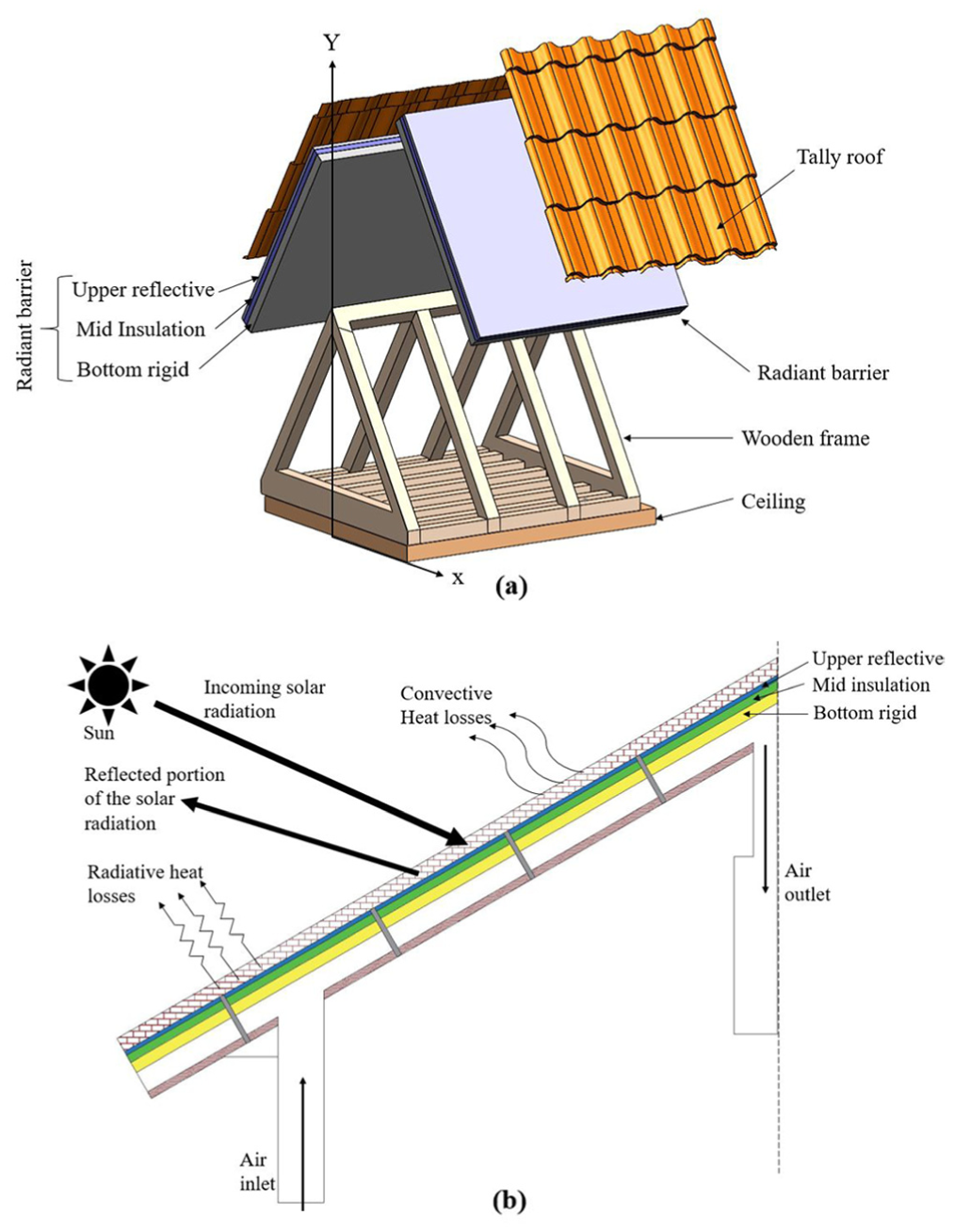
Schematic setup of the roof of a typical house equipped with the radiant barrier: (a) 3D view of roof configuration with ceiling and radiant barrier and (b) 2D view of the radiant barrier configuration with the solar radiation.
Physical model and material selection
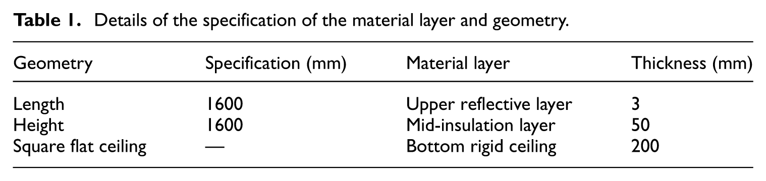
Considering a flat ceiling, having a symmetrical size of 1.6 m × 1.6 m × thickness. Primarily, three layers have been used to perform the analysis. The physical setup will have an upper reflective layer, then there will be a mid-insulation layer. There will be a rigid ceiling on the layer below, where Figure 2 shows the geometry of the proposed model. The roof assembly was modeled as a one-dimensional multilayer solid domain to evaluate through-thickness heat transfer. Since the model consists of solid layers in direct contact and does not include a ventilated air cavity, it represents a simplified multilayer roof assembly with reflective outer surfaces rather than a complete attic radiant-barrier system. Meanwhile, Table 1 lists the details of the specification of this geometry, and Table 2 shows the properties of the materials used for the upper reflective, mid-insulation, and bottom rigid layers, respectively.
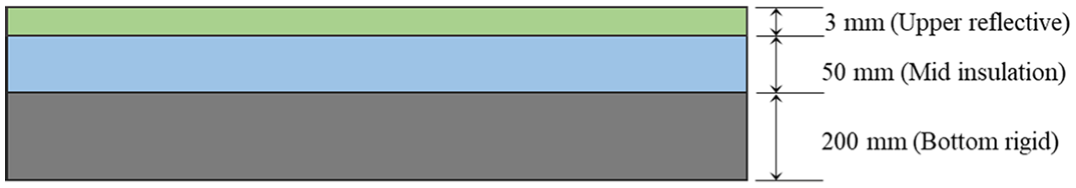
Three-layer geometry of the simplified multilayer roof assembly.
Details of the specification of the material layer and geometry.
Thermophysical and optical properties of the materials used in the numerical model.
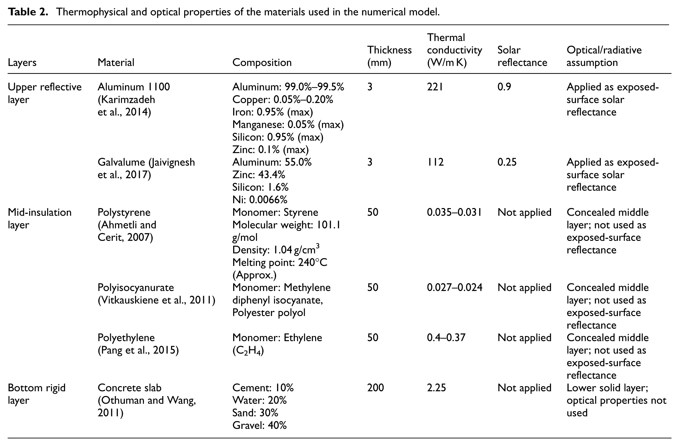
Again, the thermophysical and optical properties assigned to the materials are summarized in Table 2. Since the simulations were performed as quasi-steady thermal analyses, thermal conductivity was the primary material property used to calculate heat transfer through the solid layers. Density and specific heat capacity were not used in the steady/quasi-steady solution and are therefore not reported in the present model.
Problem formulation
The numerical simulations were conducted using the steady-state thermal module of ANSYS Workbench 2020 R1. For each material combination, the corresponding solid layers were assigned according to the geometry and material properties listed in Tables 1 and 2. Solar radiation was applied at the upper exposed surface as an absorbed heat-flux boundary after accounting for the solar reflectance of the outer layer.
The absorbed solar heat flux was estimated as:

Where
The lower surface represented the indoor-side boundary of the roof assembly. Perfect thermal contact was assumed between adjacent solid layers, and contact thermal resistance was neglected. The same modeling procedure and solver settings were used for all six combinations to ensure direct comparability.
Although the ANSYS module was used in steady-state mode, the time-dependent heat-flux profiles were generated using a sequence of independent quasi-steady calculations. At each time step, the corresponding solar radiation and ambient temperature were applied as updated boundary inputs, and the steady-state solution was recorded. Therefore, the reported 72-hour heat-flux profiles should be interpreted as quasi-steady results rather than transient thermal simulations.
For one-dimensional heat conduction through a plane wall, the general heat conduction equation can be written as:
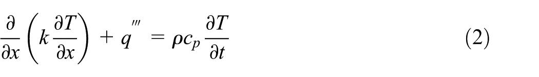
where
For steady-state conduction with constant thermal conductivity and no internal heat generation, the equation becomes (Bergman and Lavine, 2017):
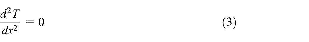
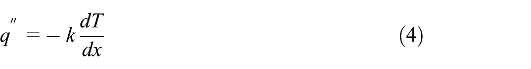
The conductive heat flux through a solid layer is expressed using Fourier’s law:
For a multilayer roof assembly, the equivalent thermal resistance per unit area can be calculated as:
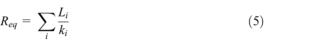
where
The heat flux through the multilayer assembly can then be estimated as:
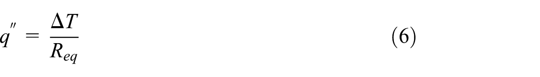
where
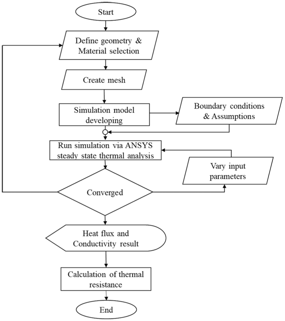
Flow chart of the proposed work.
Thermal boundary condition with ambient
The Earth’s axial tilt, which varies between 22.1° and 24.5°, plays a significant role in seasonal temperature variations. A larger axial tilt results in more pronounced seasonal temperature differences, while a smaller tilt leads to milder seasons. In this study, three axial tilt angles—23.10°, 23.45°, and 23.70° were considered to represent basis 1, basis 2, and basis 3, respectively (Sarkar and Sifat, 2016). Annual solar radiation has been taken from three sources, and later on, their average has been taken for analysis. Both solar radiation and ambient temperature were varied over time to represent changing daily boundary conditions. For each time step, the corresponding solar radiation and ambient temperature were applied as input parameters, and the model was solved as an independent quasi-steady case. Ambient temperature varies throughout the day, and the incident solar radiation considered in this study was approximately 200–800 W/m2. The thermal boundary conditions and main modeling assumptions used in the numerical simulation are summarized in Table 3.
Thermal boundary conditions and modeling assumptions used in numerical simulation.
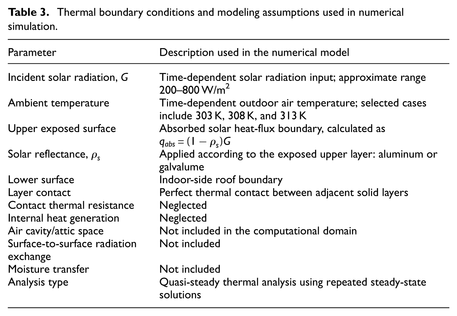
The reflective effect in the present model was represented through the solar reflectance of the exposed upper layer in the absorbed heat-flux boundary condition. Since no explicit air cavity was included, long-wave surface-to-surface radiation exchange across an attic air space was not modeled. Therefore, the boundary conditions are intended for comparative evaluation of the simplified multilayer roof assemblies rather than full attic radiant-barrier performance prediction.
Here, Figure 4 demonstrates the average solar radiation on an annual basis (Sarkar and Sifat, 2016) and a monthly basis (March; Ahmed et al., 2023). Figure 4(a) presents the average annual solar radiation, capturing the overall variation in solar radiation throughout the year. The highest radiation typically occurs during the summer months, particularly in June, when the Earth’s tilt maximizes the intensity of sunlight reaching the surface. This annual data is crucial for understanding long-term solar radiation patterns and is essential for simulating the building’s overall energy performance. Figure 4(b) shows the hourly average solar radiation for March. This graph provides detailed data on how solar radiation fluctuates throughout the day, capturing the variations in solar energy at each hour. The graph demonstrates that solar radiation increases in the morning, reaching its peak around 12:00 p.m. and then gradually decreases in the afternoon as the sun moves lower in the sky. This hourly data for March is particularly valuable because it helps in understanding how solar radiation changes over the course of a day during the transition from winter to spring. March typically experiences moderate sunlight intensity, making it an important month to study the performance of radiant barrier systems.
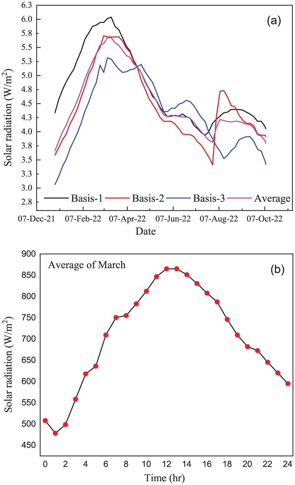
Illustration for the average solar radiation on: (a) an annual basis (Sarkar and Sifat, 2016) and (b) a monthly basis (March; Ahmed et al., 2023).
Meanwhile, Figure 5 illustrates the variation in ambient temperature throughout the day in March for three different axial tilt angles: basis-1 (23.10°), basis-2 (23.45°), and basis-3 (23.70°). The graph shows a typical diurnal cycle, where the temperature increases in the morning, peaks around midday, and decreases in the evening. The curves indicate that a higher axial tilt (basis-3) results in slightly higher temperatures, reflecting the increased solar radiation received. These temperature variations, influenced by the Earth’s tilt, highlight the seasonal impact on solar radiation and temperature, which is important for assessing building thermal performance and the effectiveness of radiant barriers.
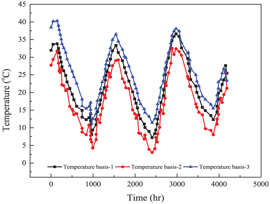
Variation of ambient temperature throughout the day in March (Sarkar and Sifat, 2016).
Meshing and validation
A square mesh was applied across the computational domain for the simplified multilayer roof assembly. The generated mesh is shown in Figure 6. The final mesh contained 665,600 elements and 2,764,853 nodes. The orthogonal quality of the mesh was 1, and the skewness was
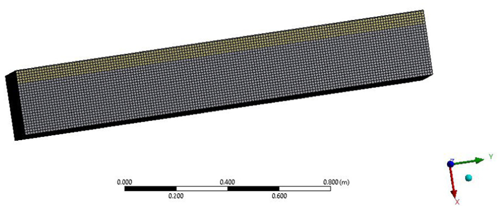
Meshing of the geometry.
Details of mesh specifications for the proposed work.
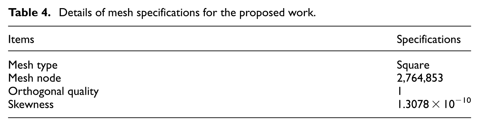
Figure 7 presents the mesh-independence analysis for combination-2 at 10 hours and 303 K. The average heat flux decreased from 61.23 W/m2 for the coarse mesh with 185,325 elements to 55.11 W/m2 for 315,175 elements and 54.07 W/m2 for 445,325 elements. Further mesh refinement to 665,600 elements produced an average heat flux of 53.84 W/m2, while the finest mesh with 985,725 elements produced 53.847 W/m2. The difference between the final selected mesh and the finest mesh was negligible, indicating that further mesh refinement had no significant effect on the predicted heat flux. Therefore, the mesh with 665,600 elements was considered sufficiently mesh-independent and was used for the remaining simulations.
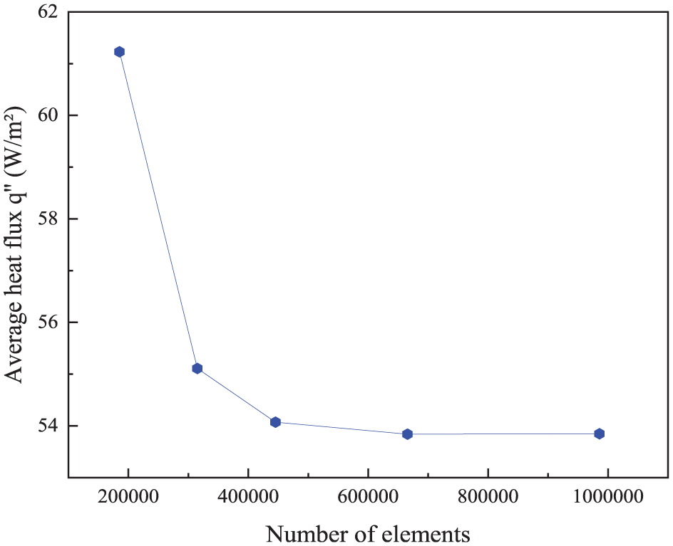
Mesh-independence analysis based on average heat flux for combination-2 at 10 hours and 303 K.
The numerical model was validated against the published experimental study of Kumar et al. (2021), who investigated a double-skin polystyrene–aluminum radiation reflector passive cool roof under arid-climate conditions. Their experimental setup consisted of two identical test rooms: one with a standard concrete roof and another with a passive cool roof incorporating a 50 mm polystyrene foam layer, a 3 mm aluminum 1100 radiation reflector, and variable air gaps of 0, 200, and 400 mm. Room air and roof surface temperatures were recorded experimentally using thermocouples and a data-logging system. In the present validation, the material layers and available boundary-condition information from Kumar et al. (2021) were reproduced as closely as possible, and the calculated heat-flux response was compared with the heat flux derived from their reported experimental temperature data. The comparison between the present numerical prediction and the published experimental data is shown in Figure 8. The maximum deviation between the present numerical result and the experimental data was 7.505%, indicating reasonable agreement for a simplified roof heat-transfer model.
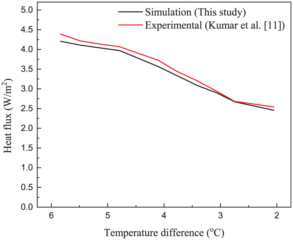
Validation of the numerical heat-flux prediction against experimental data reported by Kumar et al. (2021).
However, because the present model does not include the ventilated air gap used in the experimental system, the validation should be interpreted as a benchmark comparison for the solid-layer heat-transfer calculation rather than a complete validation of full radiant-barrier cavity behavior.
Results and discussion
Heat flux of the combination
The heat-flux results were obtained by applying the corresponding ambient temperature and solar-radiation inputs at each time step and solving the model as an independent quasi-steady case. Therefore, the reported time-dependent heat-flux profiles represent a sequence of steady-state solutions under changing boundary conditions, rather than a transient thermal simulation. Figure 9 illustrates the two types of simplified roof assemblies considered in this study: Type 1 uses aluminum as the exposed upper reflective layer, while Type 2 uses galvalume as the exposed upper reflective layer.
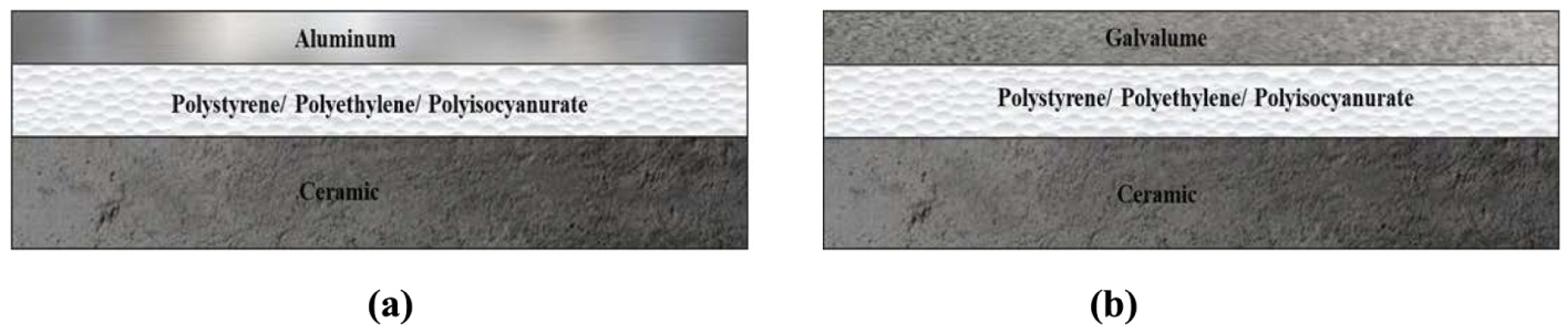
Illustration of the simplified multilayer roof assemblies: (a) Type 1 with aluminum upper layer and (b) Type 2 with galvalume upper layer.
In type 1, the total heat flux has been measured in three combinations, where the variation has been done with the mid-insulating layer. The details of type 1 are below:
Combination-1: Aluminum + Polystyrene + Ceramic
Combination-2: Aluminum + Polyethylene + Ceramic
Combination-3: Aluminum + Polyisocyanurate + Ceramic
Meanwhile, in type 2, the total heat flux has been measured for another three combinations, whereas the variation has been done similarly to the previous one with the mid-insulating layer. The details of type 2 are below:
Combination-4: Galvalume + Polystyrene + Ceramic
Combination-5: Galvalume + Polyethylene + Ceramic
Combination-6: Galvalume + Polyisocyanurate + Ceramic
Figure 10 illustrates the heat-flux distribution for the six simplified multilayer roof assemblies. Each assembly consists of an exposed upper reflective layer, either aluminum or galvalume, a concealed polymer middle layer, either polystyrene, polyethylene, or polyisocyanurate, and a bottom rigid substrate. The aluminum-based assemblies show lower heat-flux penetration than the galvalume-based assemblies because aluminum has higher solar reflectance as the exposed upper surface. Therefore, the absorbed solar heat flux is lower for aluminum-based cases. For the middle layer, polyethylene-based combinations show lower calculated heat flux in the present model; however, this should not be attributed to polyethylene solar reflectance because polyethylene is not exposed to the incident solar radiation. In this model, the solar reflectance of concealed middle layers was not applied in the absorbed heat-flux boundary condition. The observed reduction should therefore be interpreted as a result of the assigned material properties, layer arrangement, and quasi-steady conductive heat transfer assumptions.
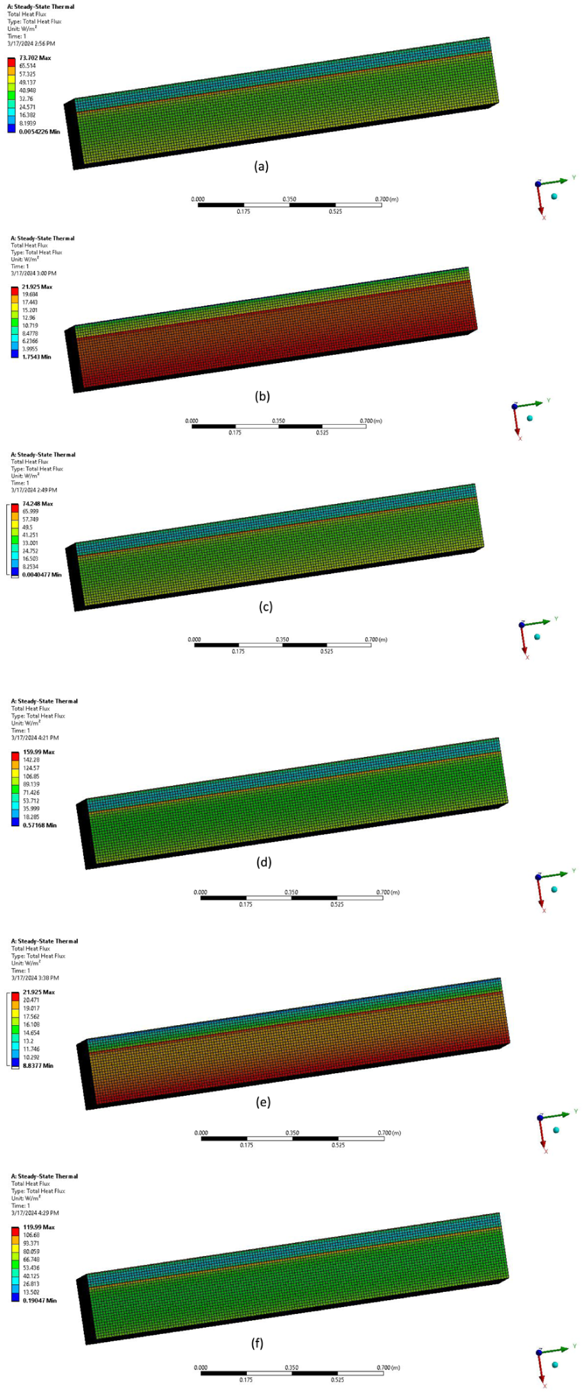
Illustration for the heat flux distribution for: (a) Combination-1, (b) Combination-2, (c) Combination-3, (d) Combination-4, (e) Combination-5, and (f) Combination-6.
Figure 11 presents the heat flux variation for the three aluminum-based assemblies over the selected three-day quasi-steady calculation period at different temperature levels of 313 K, 308 K, and 303 K. Combination-1, consisting of aluminum, polystyrene, and the rigid bottom layer, showed the highest heat-flux response, reaching approximately 95.39 W/m2 at 313 K. Combination-2, consisting of aluminum, polyethylene, and the rigid bottom layer, showed the lowest calculated heat-flux response, with values remaining much lower than those of combination-1 and combination-3. Combination-3, consisting of aluminum, polyisocyanurate, and the rigid bottom layer, showed an intermediate response. Overall, the results indicate that the calculated heat flux increases under higher-temperature boundary conditions, while combination-2 produced the lowest heat-flux values within the assumptions of the present simplified quasi-steady model.
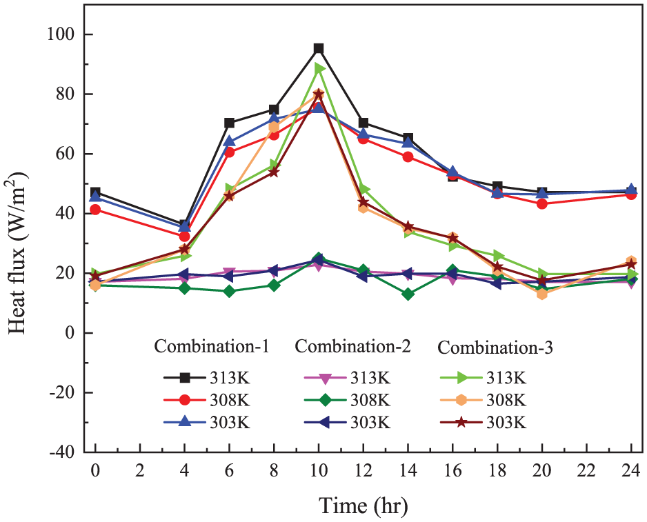
Heat flux through the combination of 3 days on a day scale.
Figure 12 illustrates the heat-flux distribution across the three aluminum-based roof assemblies over a 72-hour quasi-steady calculation period at 313 K. Combination-2 showed the lowest and most stable calculated heat flux, with values ranging from approximately 17.14 W/m2 to 24.46 W/m2 and an average value of approximately 17.97 W/m2. Combination-1 showed the highest average heat flux, approximately 56.33 W/m2, with a peak value of 95.39 W/m2. Combination-3 showed an intermediate average heat flux of approximately 37.04 W/m2. These results indicate that, within the assumptions of the present simplified multilayer model, combination-2 provided the lowest calculated heat-flux transfer among the aluminum-based assemblies.
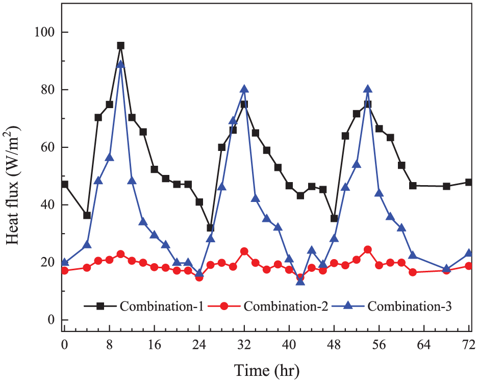
Heat flux through the combination over three consecutive days at a particular temperature of 313 K.
Figure 13 illustrates the calculated average thermal conductivity of the aluminum-based combinations over the three-day quasi-steady calculation period. Combination-2 showed slightly lower calculated average conductivity values, ranging from approximately 14.32 to 14.56 W/m·K, compared with combination-1 and combination-3, which remained around 15.32–15.35 W/m·K. However, these effective values should be interpreted as assembly-level calculated properties within the numerical model rather than intrinsic conductivities of the individual materials. Figure 14 presents the equivalent thermal resistance of the aluminum-based combinations. Combination-1 showed nearly stable equivalent thermal resistance values around 0.01648 m2·K/W, while combination-2 showed slightly higher values, ranging from approximately 0.01738 to 0.01767 m2·K/W. Combination-3 showed values close to 0.01649–0.01651 m2·K/W. These results indicate that combination-2 had the highest equivalent thermal resistance among the aluminum-based assemblies, which is consistent with its lower calculated heat-flux response.
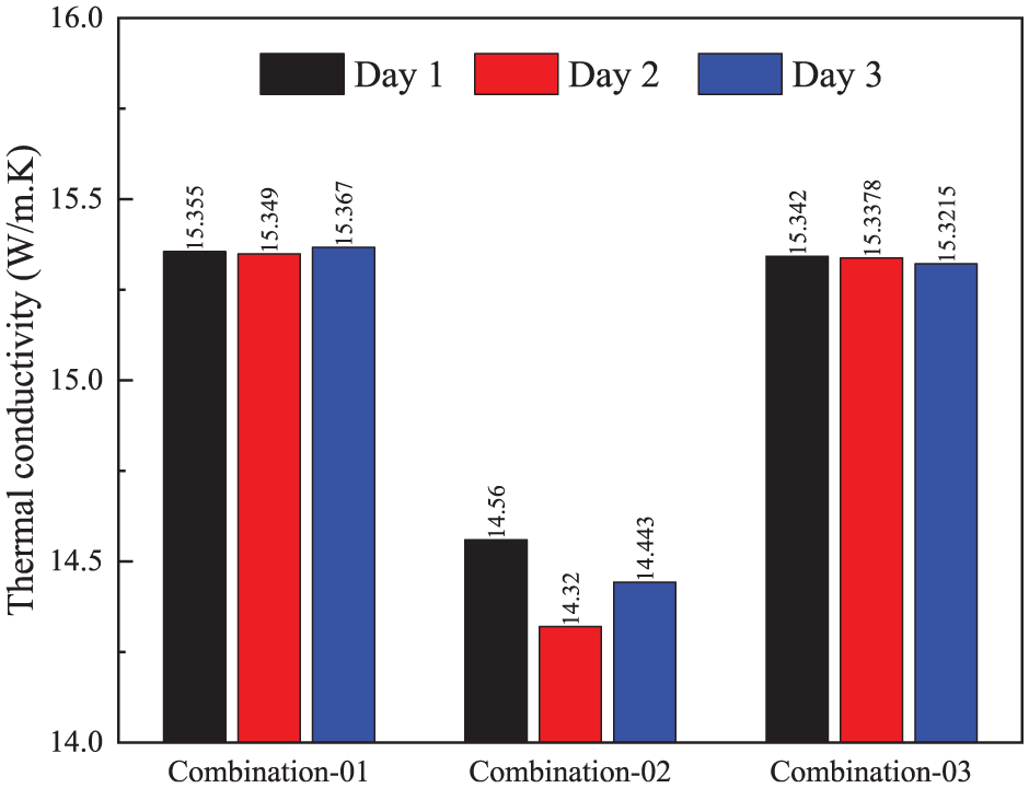
Illustration of the average thermal conductivity of different combinations of type 1 for 3 days.
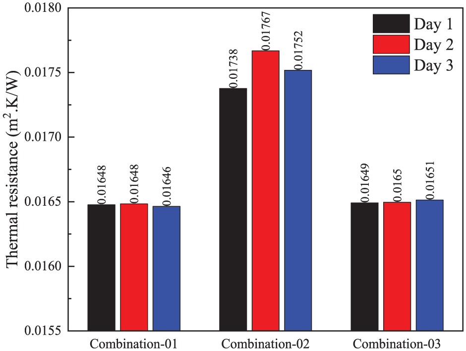
Thermal resistance of the combinations.
Figure 15 illustrates the heat-flux distribution across the three galvalume-based roof assemblies, namely combination-4, combination-5, and combination-6, over the 72-hour quasi-steady calculation period at 313 K. Combination-5, consisting of galvalume, polyethylene, and the rigid bottom layer, achieved the lowest calculated average heat flux among the galvalume-based cases, while combination-4 showed the highest heat flux. Because galvalume is the exposed upper layer in all three cases, the solar reflectance applied at the external boundary is the same for these combinations. Therefore, the difference among combinations 4–6 should be interpreted mainly in terms of the assigned middle-layer properties, the layer configuration, and the simplified quasi-steady conductive model. The result should not be explained by polyethylene solar reflectance because polyethylene is a concealed middle layer and was not treated as the exposed reflective surface.
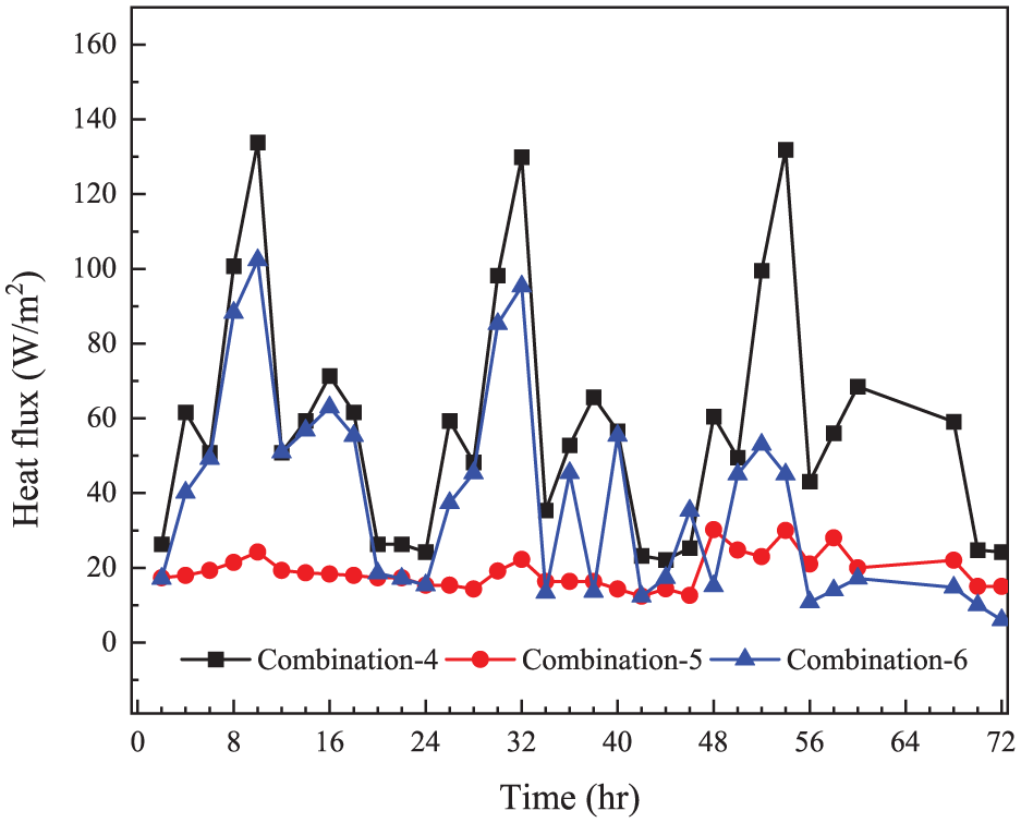
Heat flux through the combination of three consecutive days on a day scale.
Figure 16 illustrates the calculated average thermal conductivity of the three galvalume-based roof assemblies over the 3-day quasi-steady calculation period. Combination-4 showed conductivity values around 4.75–4.76 W/m·K, while combination-5 ranged from approximately 4.78 to 4.83 W/m·K. Combination-6 showed slightly lower values, ranging from approximately 4.72 to 4.75 W/m·K. The differences among the three galvalume-based assemblies were small, indicating that their calculated assembly-level conductivity values were relatively close under the selected boundary conditions.
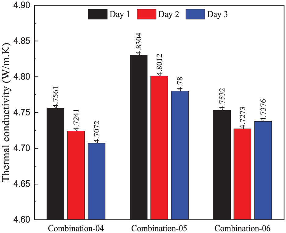
Illustration of the average thermal conductivity of different combinations of type 2 for 3 days.
Figure 17 illustrates the equivalent thermal resistance of the three galvalume-based roof assemblies over the 3-day quasi-steady calculation period. On Day 1, combination-4 and combination-6 showed similar equivalent thermal resistance values of approximately 0.05319 m2·K/W, while combination-5 showed a slightly lower value of approximately 0.05238 m2·K/W. On Day 2, combination-4 and combination-6 increased to approximately 0.05356 m2 K/W, whereas combination-5 reached approximately 0.05270 m2·K/W. On Day 3, the resistance values remained close, with combination-5 increasing slightly to approximately 0.05293 m2·K/W. Overall, the variation among the three galvalume-based assemblies was small, within approximately 1%–2%, indicating that their equivalent conductive thermal resistances were relatively similar. Therefore, the lower calculated heat flux of combination-5 should not be explained by polyethylene solar reflectance, because polyethylene is a concealed middle layer. In the present model, solar reflection is controlled by the exposed galvalume layer, which is common to all three combinations, while the middle layer affects the result through the assigned conductive properties and the simplified quasi-steady heat transfer assumptions.
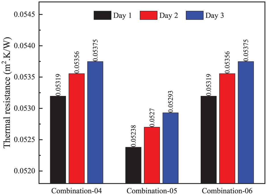
Thermal resistance of the combinations.
Figure 18 compares the equivalent thermal resistance of the individual middle-layer materials. Among the selected middle layers, polyisocyanurate showed the highest thermal resistance, approximately 1.92 m2·K/W, followed by polystyrene at approximately 1.42 m2·K/W. Polyethylene showed the lowest thermal resistance, approximately 0.131 m2·K/W. Quantitatively, the thermal resistance of polyisocyanurate was about 14.7 times higher than that of polyethylene, while polystyrene was about 10.8 times higher than polyethylene. This indicates that polyethylene is not the strongest conductive insulator when considered as an individual middle layer. Therefore, the lower heat flux observed for polyethylene-based full assemblies should be interpreted cautiously and should not be attributed to polyethylene solar reflectance, because the middle layer is not exposed to incident solar radiation. In the present simplified model, the exposed aluminum or galvalume layer controls solar reflection, while the middle layer contributes through its assigned conductive properties and its position within the multilayer assembly.
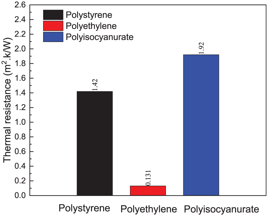
Thermal resistance of the individual mid-layer.
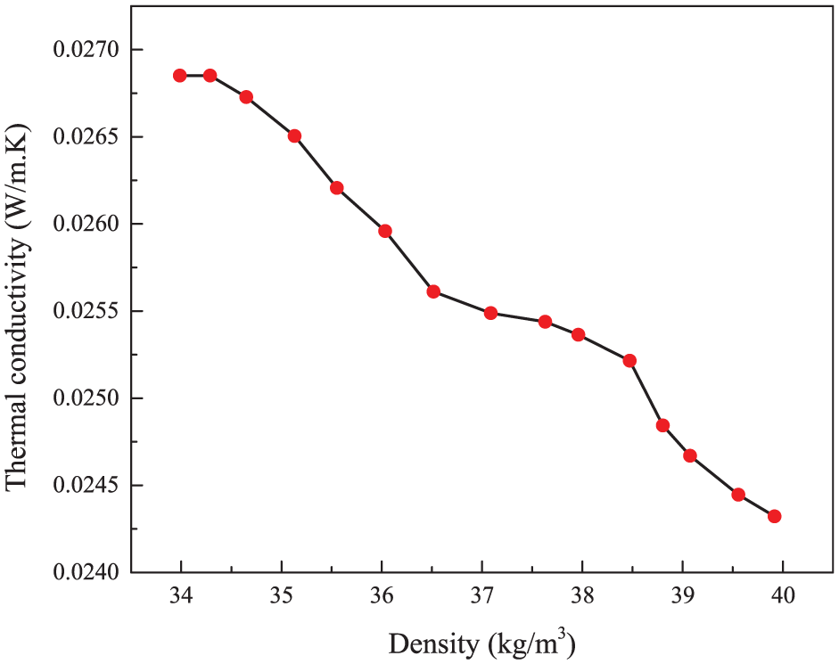
Figure 19 illustrates the effect of density on the thermal conductivity of polyethylene. As the density of polyethylene increases, its thermal conductivity decreases, meaning that denser polyethylene is more effective at insulating against heat transfer. This suggests that higher-density polyethylene has a more compact structure that reduces the movement of heat through the material. Similarly, Figure 20 illustrates the effect of density on the thermal conductivity of polyisocyanurate. As the density of polyisocyanurate increases, its thermal conductivity also decreases, indicating that denser polyisocyanurate provides better insulation by limiting heat transfer through its tightly packed structure. This study is important because it highlights how the density of materials can significantly affect their thermal performance, providing valuable guidance for optimizing radiant barrier systems to improve energy efficiency in buildings.
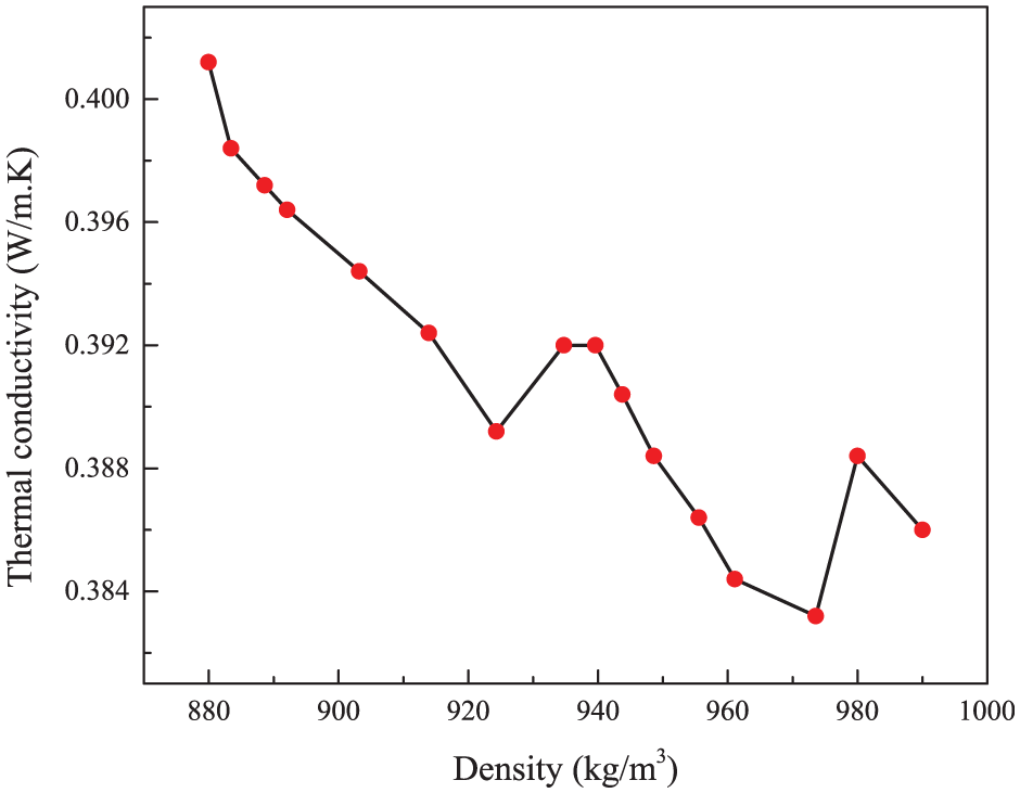
Change in thermal conductivity with density of polyethylene.
Change in thermal conductivity with the density of polyisocyanurate.
Figure 21 compares the average heat-flux values obtained in the present study for combinations 2 and 5 with the experimental findings reported by Ashhar and Lim (2020). They measured heat-flux penetration through roof assemblies with reflective air spaces at a constant temperature of 306 K, reporting values of 22.34 W/m2 for clay tiles at 30°, 25.86 W/m2 for clay tiles at 45°, 32.49 W/m2 for concrete tiles at 30°, and 34.40 W/m2 for concrete tiles at 45°. In the present study, the average heat fluxes of combination-2 and combination-5 were approximately 17.97 W/m2 and 19.01 W/m2, respectively, at 313 K. Although the geometry and boundary conditions differ between the two studies, the comparison provides a useful benchmark showing that the selected multilayer assemblies produced lower calculated heat-flux values under the assumptions of the present model. Therefore, this comparison should be interpreted as indicative rather than as a direct one-to-one validation.
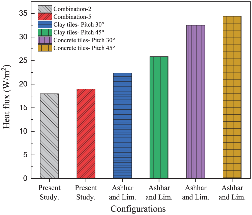
Comparison of average heat flux through combinations 2 and 5 with experimental findings from Ashhar and Lim (2020).
Conclusion
The present study evaluated the thermal performance of six simplified multilayer roof assemblies for hot-climate applications using quasi-steady numerical simulations. Aluminum or galvalume was used as the exposed upper reflective layer, while polystyrene, polyethylene, or polyisocyanurate was used as the concealed middle layer over a rigid bottom substrate. The model was developed to compare relative heat-flux reduction and equivalent thermal resistance under identical boundary conditions. The results highlight the importance of exposed-surface solar reflectance, layer arrangement, and conductive material properties in reducing heat transfer through roof assemblies. The specific findings are listed below:
The aluminum-based roof assemblies showed lower calculated heat-flux transfer than the galvalume-based assemblies, mainly because aluminum has higher solar reflectance as the exposed upper surface. Therefore, the absorbed solar heat flux was lower for aluminum-based configurations.
Combination-2, consisting of aluminum, polyethylene, and the rigid bottom substrate, produced the lowest average heat flux among the aluminum-based assemblies. At 313 K, its average heat flux was approximately 17.97 W/m2, compared with approximately 56.33 W/m2 for combination-1 and 37.04 W/m2 for combination-3.
Combination-5, consisting of galvalume, polyethylene, and the rigid bottom substrate, produced the lowest average heat flux among the galvalume-based assemblies. Its average heat flux was approximately 19.01 W/m2, compared with approximately 58.39 W/m2 for Combination-4 and 38.21 W/m2 for combination-6.
The equivalent thermal-resistance results showed that the differences among some material combinations were relatively small; therefore, heat-flux reduction should not be explained by one material property alone. Instead, the calculated performance depends on the combined effects of exposed-surface reflectance, assigned conductive properties, layer arrangement, and the quasi-steady modeling assumptions.
Since polyethylene was used as a concealed middle layer, its solar reflectance was not applied as an exposed-surface boundary condition. Therefore, the lower calculated heat flux of polyethylene-based assemblies should not be attributed to polyethylene solar reflectance. Solar reflection was controlled by the exposed aluminum or galvalume layer, while the middle layer affected the calculated heat transfer through its assigned conductive properties and position in the multilayer assembly.
Although the present results provide useful comparative insight into selected reflective and insulating roof-layer combinations, the model has several limitations. The computational domain did not include a ventilated air cavity, detailed surface-to-surface radiation exchange, moisture transport, or full transient weather-driven heat transfer. Therefore, the findings should be interpreted as a comparative assessment of simplified multilayer roof assemblies rather than a complete prediction of full attic radiant-barrier performance. Future work should extend the model by incorporating ventilated air spaces, long-wave radiation exchange, moisture effects, real climatic data, life-cycle cost analysis, and full-scale experimental validation under local hot-climate building conditions.
Footnotes
Acknowledgements
The authors appreciate and acknowledge the Khulna University of Engineering & Technology for providing the facilities throughout this work.
Author contributions
Funding
The authors received no financial support for the research, authorship, and/or publication of this article.
Declaration of conflicting interests
The authors declared no potential conflicts of interest with respect to the research, authorship, and/or publication of this article.
Data availability statement
The data that support the findings of this study are available from the corresponding author upon reasonable request.*