
Abstract
This study presents a methodology to find the optimal sequence and thicknesses of individual material layers in a multilayer armour module. The methodology is demonstrated with application to three different metal alloys: Armox-500T, Ti-6Al-4V and Al-2024. Numerical simulations are performed first to study the ballistic impact behaviour of these three materials using AUTODYN-3D code. The results of numerical simulations are compared with experimental results for validating the numerical models. Thereafter, a three-layer armour module consisting of these three materials is optimized to defeat 7.62 armour piercing projectile with minimum weight. The optimization process involves carrying a set of numerical simulations based on the design of experiment approach to generate a response surface for the ballistic performance of a composite module. A new ballistic performance parameter is introduced to measure the ballistic response of the module by combining depth of penetration and residual velocity of the projectile to bring uniformity between two cases of partial and complete penetration. The proposed parameter provides more information on ballistic performance. The response surface for ballistic performance parameter is generated in terms of thicknesses for six possible combinations of three material layers. The adequacy of the proposed optimization scheme is confirmed with ballistic experiments. The sequence Armox-500T/Ti-6Al-4V/Al-2024 with thicknesses 5.5, 8.5 and 13 mm, respectively, is found to be the best against 7.62 mm armour piercing projectile. Furthermore, the performance of each individual material is compared with an optimized three-layer armour module. The composite module is found to be weight efficient over Armox-500T, Al-2024 and provides better thickness efficiency over Al-2024. The weight efficiency and thickness efficiency of Ti-6Al-4V are found to be comparable to the composite module. This study emphasizes the necessity of developing new procedures to provide reliable estimates of design parameters for a multilayer armour module.
Introduction
Fast mobility, transportability and fuel efficiency are very important for any armoured vehicle in a battlefield. Thus, there is a great demand for designing lightweight armour structures to meet these specifications. The lightweight armour structures can be built either by developing more efficient new materials or by combining already available potential armour materials in different layers of a composite armour. All modern armoured vehicles from main battle tanks (MBTs) to infantry combat vehicles (ICVs) use composite armour, which consists of layers of different materials such as metal alloys, ceramics, plastics and fibre-reinforced polymers. Use of the same material in different layers with or without gap does not offer much advantage in terms of ballistic protection. It is found in experimental studies that a monolithic block offers better ballistic protection in comparison to a multilayer block of the same material having an equal thickness (Gupta and Madhu, 1997; Zukas, 1996; Zukas and Scheffler, 2001). In contrast, there are studies which suggest that the ballistic protection capability and weight efficiency of the composite module made of different material layers are better than their monolithic counterparts. Ben-Dor et al. (2012a) discussed various works related to the protective properties of multilayer metal modules. Composite armour of alumina (Al2O3) backed by aluminium 6061T3 plate offers substantial weight saving and also performs better compared to their individual constituents or armour steel for the same ballistic threat. Although ceramic material has a very high compressive strength, it is very weak under tensile loading. State of tensile stress can be altered in the ceramic plate by using a suitable backing to improve the overall resistance of the composite armour against tensile stresses (Espinosa et al., 1998; Wilkins, 1978). Experimental results show that a three-layer composite armour with first frontal hard layer of alumina (Al2O3) followed by the second layer of Dyneema HB25 and the third layer of porous polyurethane foam is more effective in comparison to a monolithic steel-4140 (armour grade) plate of same aerial density for providing ballistic protection (Ong et al., 2011; Poh, 2008). These studies also highlight the important role played by each layer. The frontal ceramic layer of alumina (Al2O3) causes significant plastic deformation in the projectile because of its very high compressive strength. The second layer of orthotropic composite Dyneema HB25 spreads the shock waves laterally away from the incident axis, which causes significant stress wave attenuation and increases the area for energy absorption. The third layer of porous polyurethane foam absorbs the remaining energy by compressing its pores and finally converts it into heat. It also helps in preventing spall failure in the armour module. Light metal alloys of aluminium, magnesium, titanium and fibre-reinforced epoxy resin (e.g. aramid-epoxy) in combination with ceramics such as Al2O3, B4C and SiC provide better solutions for protection against 7.62 armour piercing (AP) and 12.7 AP projectiles (Plonka et al., 2015; Senderski et al., 2011). A layered block with a proper combination of high and low impedance materials can substantially enhance the stress wave attenuation. A three-layer combination of concrete–polystyrene–concrete and sand–polystyrene–concrete has been proven to be extremely effective in mitigating impulsive loading like a blast wave (Tedesco and Landis, 1989). The load spreading capability of a material layer on top of some other material can be used to develop better armour solutions. The use of SiC, poly methyl methacrylate (PMMA) and copper as a top layer to spread the load over the Al-6061 plate is studied in detail by Gupta and Ding (2002) and Robbins et al. (2004). The aforementioned discussion suggests that multilayer armour has great potential to meet current and future protection requirements; however, designing a multilayer armour module is a challenging task.
Finding the correct sequence of material layers and the optimum thickness of each layer in a composite module is not straightforward. Achieving optimum design experimentally may take longer time and a large number of expensive tests will also increase the cost of the design process. An alternative is to make use of modelling and simulation of ballistic impact for design purposes. In the literature, semi-empirical, analytical and advanced numerical models have been employed to simulate a ballistic phenomenon. Various important analytical models for penetration mechanics have been discussed in detail by Ben-Dor et al. (2005, 2013) and Anderson (2017). Using the localized interaction model (LIM) for ballistic penetration, Ben-Dor et al. (1999, 2011, 2013) discussed the solution procedure for optimal sequence and thicknesses of different layers. It was found that various layers should be arranged in increasing order of the ratio of distortional pressure (a material property) to the density of the material for a rigid penetrator (Ben-Dor et al., 1999). Optimum thicknesses can be determined after arranging material layers in this order as explained by Ben-Dor et al. (2011). Similarly, Aptukov et al. (1986) solved for optimal thicknesses by modelling the penetration process as the radial expansion of a hole. Optimal design parameters are estimated for armour module using the Florence penetration model (Florence, 1969) with the frontal ceramic plate backed with metal alloy or fibre-reinforced composite like glass fibre-reinforced polymer (GFRP) (Ben-Dor et al., 2000; Hetherington, 1992). These analytical models are also used in many studies to optimize the shape of impactor to maximize depth of penetration (DOP) or to minimize the ballistic limit velocity (BLV) (Ben-Dor et al., 2012b). The major advantage of using these simplified models for multilayer shields is that the ballistic response variables such as residual velocity (RV), BLV and DOP can be directly expressed in closed form as a function of design variables like thicknesses of various layers. This simplifies the formulation of optimization problem for designing the composite module.
Analytical models unequivocally simplify the optimization problem; however, use of these models is restricted to few applications because of their simplified assumptions. These assumptions include rigid and conical nature of impactor (Ben-Dor et al., 2013), a particular combination of material layers like ceramic frontal layer backed with metal alloys or fibre-reinforced composites (Florence, 1969). All analytical models also require calibration of material parameters from actual full-scale experiments of ballistic impact. The aforementioned shortcomings can be easily tackled by advanced numerical models in the present scenario. These numerical models work with very few assumptions so that the model can work universally for different scenarios and predict results very close to the actual reality. The models solve the non-linear partial differential equations (PDEs) representing an impact event. The governing equations are obtained by incorporating extreme material behaviour (large plastic deformation, high strain rate, high temperature and pressure) into the laws of conservation of mass, momentum and energy for a continuum media. It is difficult to get closed-form solutions for these non-linear PDEs. Therefore, the techniques like finite element method (FEM), finite difference method (FDM) and finite volume method (FVM) are employed to solve these equations along with advanced contact algorithms to handle the interaction of projectile and target. A powerful computing system can quickly solve a large system of algebraic equations obtained after discretizing the aforementioned PDEs in space and time. The numerical solvers like Abaqus, AUTODYN-3D and LS-Dyna designed based on the aforementioned techniques are commercially available to solve for impact events.
The main goal of optimization of an armour module is to maximize its ballistic performance with constraints mainly on weight, thickness and cost. Impact problems are highly non-linear in nature, and it is difficult to directly formulate the objective function in terms of design variables in numerical solvers. Therefore, various constraints on design variables and ballistic response are not forced initially in the numerical model for optimization of the armour module. Instead, simpler two-step staggered approaches are preferred (Kędzierski et al., 2015; Kurtaran et al., 2003; Park et al., 2005). In this study, a two-step staggered approach is used to optimize a three-layer armour module consisting of three different materials (Armox-500T, Ti-6Al-4V and Al-2024) to defeat 7.62 AP projectile with minimum weight. In the first step, the ballistic response is computed using the numerical model for different combinations of design variables under the design of experiment (DOE) framework. Numerical modelling is performed using AUTODYN code. In the second step, the ballistic response is expressed in closed form in terms of design variables using regression analysis. The ballistic response is measured in terms of a new parameter ballistic performance parameter (BPP) instead of traditionally used ballistic response parameters such as RV and DOP. Finally, conventional optimization methods are employed to design armour modules for various constraints.
Numerical modelling and simulation
Numerical modelling of bullet impact
In this study, numerical modelling of bullet impact is carried out in AUTODYN-2D/3D, an explicit software for non-linear dynamics from ANSYS. Anderson (1987), Wriggers (2006) and Zukas (2004) provided a detailed description of the fundamentals of these numerical models also known as Hydrocodes. The numerical models solve equations of conservation of mass, momentum and energy for continuous media. They require a description of material behaviour (discussed subsequently) in the form of an equation of state, strength and failure model for a material along with the initial conditions. A two-dimensional (2D) axis-symmetric model which takes into account the symmetry of the problem is created using Lagrangian solver in AUTODYN. The use of axis-symmetric simplification makes the computation lighter by reducing one entire dimension. The Lagrange solver is computationally fast and provides a good representation of material interfaces. It is observed in experimental studies that the lead-cap and brass jacket affect the ballistic performance only by 2%–3% against metallic targets (Børvik et al., 2009). Therefore, only the core of 7.62×54R AP projectile is modelled. The dimensions of the projectile core chosen for numerical simulation are shown in Figure 1. In all our experiments, the bullet was fired with full charge at a normal angle to the target. A variation of
The core of 7.62×54R AP projectile (all dimensions are in mm).
Description of material behaviour
Strength model
Deformation history, strain rate and temperature affect the strength of metallic alloys. Johnson and Cook (1983, 1985) developed a phenomenology-based strength model, which combines the effects of these three aspects. The Johnson–Cook model is popular in the fields of high-velocity impact and dynamic response of materials. The model is simple and easy to use in numerical models. This model is adopted in this study to describe the behaviour of materials under high-velocity impact. The strength model is expressed as

where σ is the Von Mises flow stress of the material,
The materials used in this study are Armox-500T, Ti-6Al-4V and Al-2024. These materials are well studied at higher strain rates and varying temperatures in the literature. The values of these parameters are taken from the literature. Armox-500T is studied by Iqbal et al. (2016) and Skoglund et al. (2006). The properties of Armox-500T are taken from the study by Skoglund et al. (2006). The properties of Ti-6Al-4V and Al-2024 metal alloys are taken from the study by Leseur (1999). The five parameters of material strength model for these three materials are given in Table 1. A 7.62 AP bullet is modelled as a rigid projectile for which a very high value of A (5,00,000 MPa) is chosen in the Johnson-Cook strength model and no failure model is chosen. All other properties of bullet are kept the same as Armox-500T steel.
JC material parameters for Armox-500T, Ti-6Al-4V and Al-2024.
Fracture model
A phenomenological failure model developed by Johnson and Cook (1985) is used in the numerical model to capture the fracture behaviour of materials. This model takes into consideration the effects of stress state (stress triaxiality), temperature and strain rate on the final failure strain of the material. The fracture model in its basic form is expressed as

where

where
The five parameters of material failure model for Armox-500T, Ti-6Al-4V and Al-2024 are given in Table 1. The values are taken from literature studies (Leseur, 1999; Skoglund et al., 2006), where behaviour of these materials is studied at higher strain rates, varying temperatures and different states of stress (triaxiality ratios) to determine JC failure model parameters.
Ballistic evaluation and testing
Ballistic evaluation
A bullet may penetrate completely or partially in an armour module. We can record the DOP and back face bulge for a partially penetrated module. RV can be recorded in the case of full or complete penetration. To bring uniformity between these two cases of partial and full penetration, we have measured ballistic performance in terms of a new normalized parameter. This ballistic performance parameter (BPP) considers DOP as well as RV to measure the final ballistic performance and thus provides more information on the ballistic performance of a target. The expression for BPP is given by

where T is the total thickness of the module, BFB is the back face bulge, DOP is the depth of penetration, RV is the residual velocity and IV is the impact velocity.
Different quantities used in the aforementioned equation are shown in Figure 2. BPP value will always lie in the range

(a) Initial configuration – bullet hitting target with some impact velocity (IV), (b) partial penetration – DOP and BFB measurement and (c) complete penetration – bullet going out with some residual velocity (RV).
The measurement of DOP and BFB can be quite involved in the case of low-velocity impacts where the global deformation of structure becomes important. In such cases, another easy way to describe penetration of target is to simply note the distance between front tip of the bullet (or front tip of crater created by the bullet) and back surface of the target along the thickness direction. When this distance is equal to the initial total thickness of the target, the first term of BPP can be set to zero. Similarly, when the distance between front tip of the bullet and back surface of target becomes zero, the first term can be set to one. All other values of this distance can be correspondingly normalized to set this first term between zero and one. It should also be noted that in cases where global deformation of structure is important we may have to put additional constraint on the deflection of structure while designing protective modules.
A bullet is said to be successfully defeated by an armour module if BPP value is less than 100. On a safer side, it will always be better to choose values of BPP ⩽ 95 for designing purposes depending upon the total thickness and the allowable values of back face bulge.
Advantages of BPP over traditional ballistic performance measures
DOP, RV and BLV are the widely used ballistic performance measures for the design of armour modules. DOP fails to distinguish the performance of two different arrangements of material layers in the case of full penetration for different RVs. Clearly, the ballistic performance of the sequence with lower RV is better. It is important to limit the DOP and back face bulge in the target while designing the armour module. However, the performance measure RV alone cannot provide any information about the penetration of the target by the bullet. Our ballistic performance measure will be more useful in the design of armour module as it contains information on DOP as well as RV. BLV of a target against a given projectile is the maximum impact velocity of the projectile at which the target can completely defeat or stop it. A numerical solver may require carrying iteratively a set of runs to solve for BLV of a module, which is a time-consuming process. In contrast, our ballistic performance measure BPP can be computed easily in a single run.
Ballistic testing
Some selected experiments were conducted in a small arm range for validation of numerical models. The projectile was fired at normal angle to the armour module from a distance of 10 m. Instrumented velocity measuring device was used to measure the impact velocity of the projectile during testing. Each test was repeated two to three times to check the repeatability of the experiment. After the test, the front and back faces of the plates were photographed and important data like DOP and back face bulge were also recorded for comparison with numerical simulations. The detailed description of the ballistic test setup can be found in the studies by Jena et al. (2009) and Savio et al. (2011). The clamping arrangements for ballistic testing of modules are shown in Supplemental Figure S1.
Response surface methodology
Response surface methodology (RSM) is a useful technique to derive an approximate relationship between the response variable and set of independent variables affecting it (Montgomery, 2012; Myers et al., 2016). In this study, BPP for a multilayer module is the response variable which is affected by the thicknesses of the individual material layers

The core of RSM is the proper choice of experiments or numerical simulations to find model parameters in the aforementioned equation. This systematic choice of experiments is also known as response surface design. Response surface design reduces the number of runs, provides a good distribution of design points, and also helps in clearly analysing the effects of individual variable and their interactions on the response variable. The important response surface designs for polynomial models are central composite design (CCD) and Box–Behnken design. In the case of non-standard models, design points can be chosen based on various optimality criteria and accordingly there are various response design schemes such as D-optimal and I-optimal designs. Space filling designs such as Latin hypercube design and orthogonal array-based Latin hypercube design are other important experiment design schemes for computer-based experiments. More detailed discussion on response surface design can be found in Montgomery (2012) and Myers et al. (2016).
We have used CCD scheme to approximate the relationship between BPP and independent variables
Results and discussion
Ballistic performance of monolithic metal plates
High strain behaviour of all three metallic alloys considered in this study is well studied in the literature (Iqbal et al., 2016; Leseur, 1999; Skoglund et al., 2006). Thus, a numerical study along with few selected ballistic experiments is preferred to evaluate their ballistic performance. The major goal of numerical study is to find the critical thicknesses for individual material which can defeat 7.62 AP Projectile. The critical thickness data will be used to design experiments for evaluating the ballistic response surface of the multilayer module.
The effects of mesh size and erosion strain were studied first on a numerical solution. Mesh near the critical impact zone for the target is shown in Figure 3. Effect of mesh size is studied on RV of the projectile for all three materials. Meshes of element size h × h, 2.5h × h and h × 2.5h (mm) are created in the critical impact zone for a 6-mm-thick plate and ‘h’ is varied from 2 to 0.1. The variation in RV with different mesh sizes is shown in Figure 4. Optimal mesh size of 0.25 × 0.1 (mm) is selected based on this sensitivity analysis.
Refined meshing near the critical impact zone.
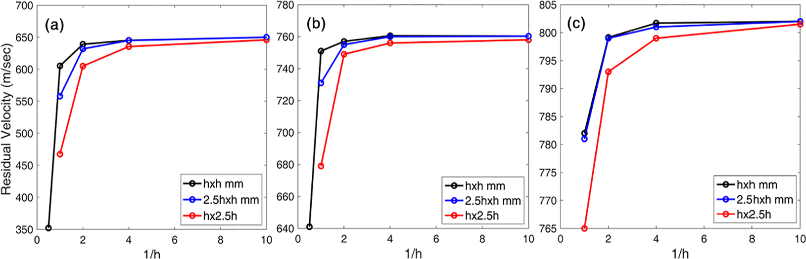
Variation in residual velocity for 6-mm plate with different mesh sizes for (a) Armox-500T, (b) Ti-6Al-4V and (c) Al-2024.
Erosion strain is a numerical mechanism for removing extremely distorted elements from the simulation before they become degenerate. RV of the projectile is studied with different erosion strain (geometric) values 0.5, 1, 1.5, 2, 4 and 5, and the results are shown in Supplemental Figure S2. No significant changes are observed on varying the erosion strain from 2 to 5 for all three materials. Numerical solver did not encounter any problem of degenerate elements even for higher values of 4 and 5, and therefore, we selected the erosion strain value of 4 given in Table 1. Ballistic performance of the three selected materials as a function of thickness is plotted in Figure 5. The results of numerical simulations are summarized in Tables 2 to 4.
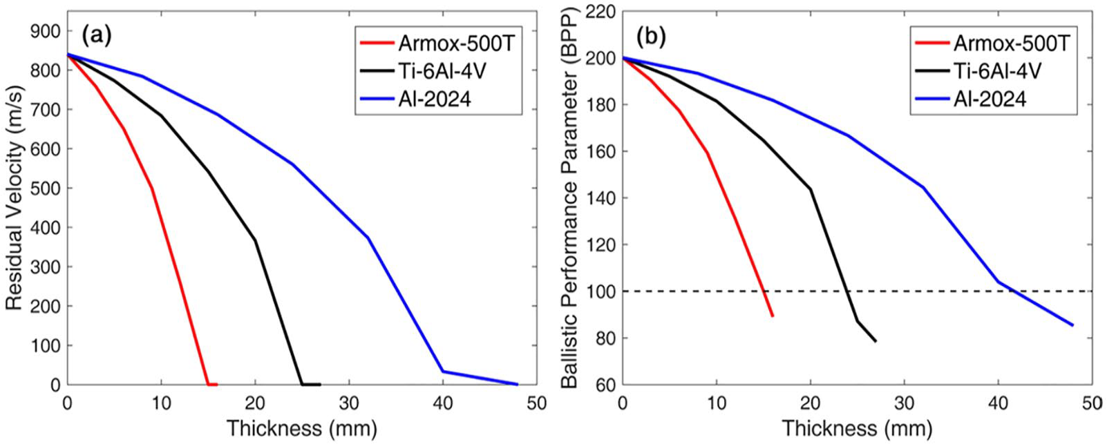
Plot of (a) residual velocity and (b) ballistic performance parameter with thicknesses of plates.
Numerical simulation results of ballistic performance of Armox-500T.
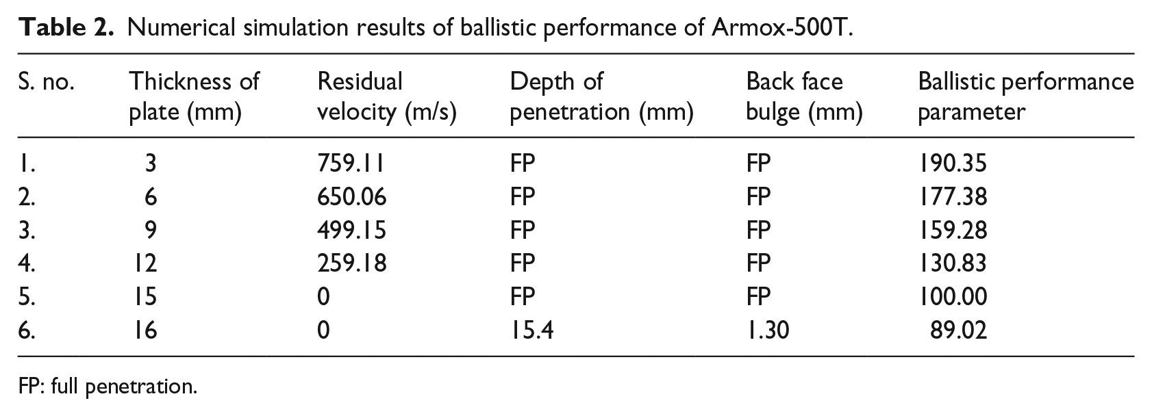
FP: full penetration.
Numerical simulation results of ballistic performance of Ti-6Al-4V.
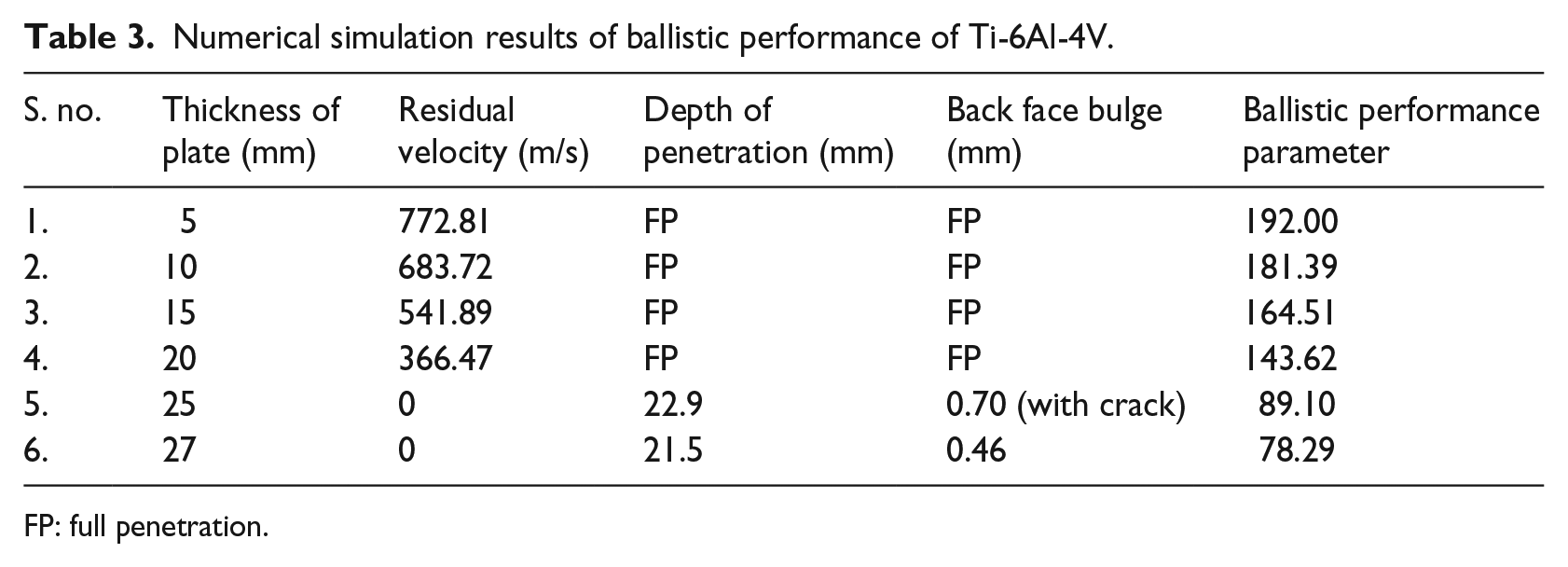
FP: full penetration.
Numerical simulation results of ballistic performance of Al-2024.
FP: full penetration.
Numerical simulations are performed with the aim of determining the critical thicknesses of the plates to defeat the projectile. The critical thicknesses which can defeat 7.62 AP bullet with minimum weight are approximately 16 mm for Armox-500T, 26 mm for Ti-6Al-4V and 46 mm for Al-2024. Efficiency of an armour material is generally measured in terms of weight and thickness. A weight efficient material is the one which can defeat the projectile with minimum weight and a thickness efficient material requires relatively less thickness to defeat the projectile. Out of these three materials, Ti-6Al-4V has highest weight efficiency and Armox-500T offers the highest thickness efficiency.
The motion of projectile during the impact event is described with projectile velocity and deceleration. The projectile velocity and deceleration experienced by the projectile during penetration through the target of critical thicknesses for all three materials are shown in Figure 6. Deceleration is plotted after filtering high-frequency components. Projectile experiences maximum resistance force in the case of Armox-500T steel and stops in short period of time. Al-2024 offers least resisting force and accordingly takes longer time to stop the projectile.
Plots of (a) projectile velocity and (b) deceleration with time during penetration for critical thicknesses 16 mm Armox-500T, 26 mm Ti-6Al-4V and 46 mm Al-2024.
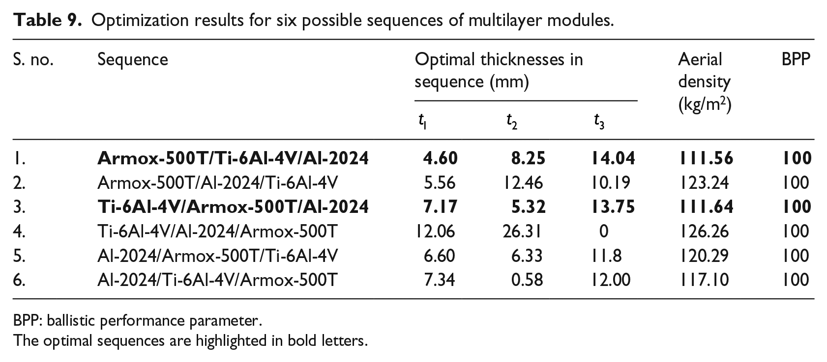
Ballistic experiments are conducted to validate the numerical model. Plates of thicknesses 15 mm for Armox-500T, 25 mm for Ti-6Al-4V and 50 mm for Al-2024 are fired against 7.62 AP projectile at normal angle. Every experiment was performed two to three times to check the repeatability of the results. The results of experiments on three plates are shown in Supplemental Figure S3. The closer view of front and back sides of the plates after the projectile impact is shown in Figure 7. The comparison of experimental and numerical results for monolithic plates against 7.62 AP projectile is shown in Table 5. A good agreement is found between numerical models and experiments as shown in Figures 8 and 9. Numerical models are accurately representing the impact phenomenon.
Results of ballistic experiments on monolithic plates: front and back sides of (a) 15 mm Armox-500T plate, (b) 25 mm Ti-6Al-4V plate and (c) 50 mm Al-2024 plate.
Comparison of experimental and numerical results for monolithic plates.
FP: full penetration.
Results of numerical simulations for monolithic plates: (a) 15 mm Armox-500T plate, (b) 25 mm Ti-6Al-4V plate and (c) 50 mm Al-2024 plate after bullet impact.
Sectional views of monolithic plates after ballistic testing for (a) 15 mm Armox-500T plate, (b) 25 mm Ti-6Al-4V plate and (c) 50 mm Al-2024 plate after bullet impact.
Ballistic performance and optimization of multilayer module
Response surface for ballistic performance of multilayer modules
As discussed earlier, the ballistic performance of a multilayer module is affected by the sequence of material layers and their thicknesses. There are six possible sequences for three material layers. Therefore, the response surface for BPP is generated for all six combinations using numerical simulations in order to find optimal sequence and thicknesses. In each sequence, the thicknesses of the individual layers were varied as per CCD to capture combined and individual effects of each layer. A sample CCD3 array for thicknesses
CCD3 array for sequence Armox-500T (front)/Ti-6Al-4V (middle)/Al-2024 (back).
CCD: central composite design.
In numerical simulations, all the plates are freely touching each other and their edges are kept clamped similar to the experimental conditions. The results of numerical simulations are summarized for one of the sequences in Table 7. Results for other five sequences are not shown here for brevity. Please refer to Supplemental Tables S1 to S4 to check the ballistic performance results for other sequences.
Ballistic performance of the sequence Armox-500T (front)/Ti-6Al-4V (middle)/Al-2024 (back).
FP: full penetration.
Regression is used to investigate the relationship of BPP parameter with thicknesses of six different sequences. Thicknesses of different layers are the explanatory variables. The dependent variable BPP is expressed in terms of these thicknesses. The interaction terms are also included in regression models for the comprehensive understanding of relationships among the variables. Significance of all the terms is evaluated at a significance level of 0.05. Generally, the adequacy of regression models is evaluated with a statistical measure R2. However, each explanatory variable added to a regression model increases R2. Our models have more terms and thus there is a chance of getting a higher value of R2 due to mathematical artefacts. Adjusted R2, a modified version of R2, adjusted for number of predictors in the model is used to evaluate the performances of statistical models. This gives information on the percentage of variability explained by only those explanatory variables which actually affects the dependent variable. The results of regression analysis are summarized in Table 8.
Regression models for BPP as a function of thicknesses of individual material layers for six possible sequences.
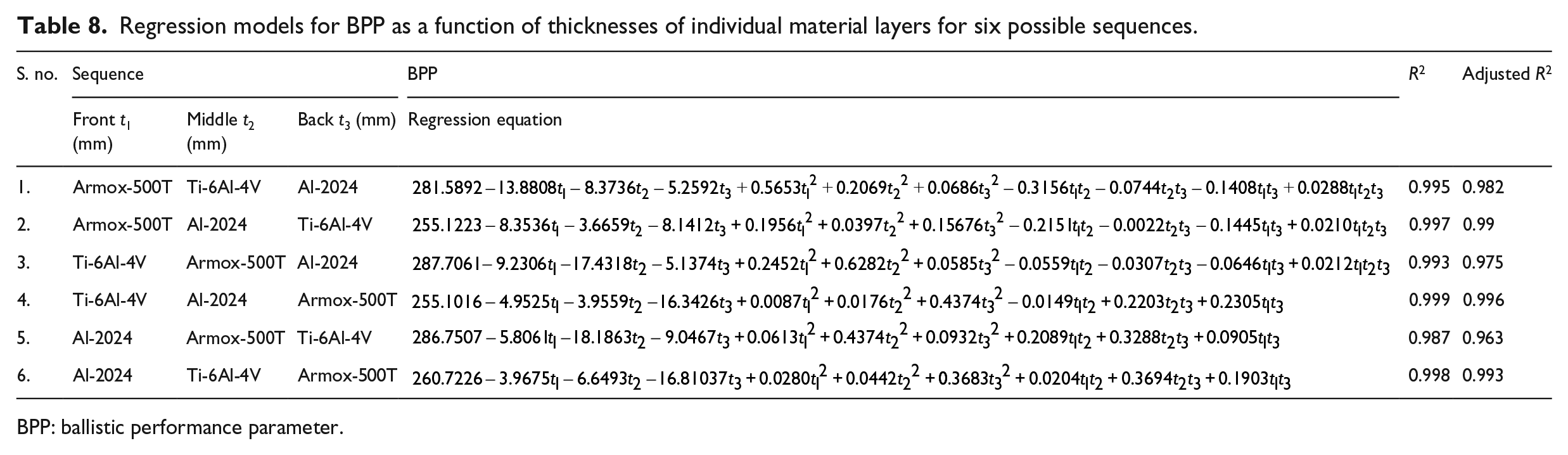
BPP: ballistic performance parameter.
Optimization of multilayer module
The goal of the optimization study is to defeat the projectile with minimum weight. After generating the response surface for BPP in terms of thicknesses of individual material layers, optimization problem is formulated as


In the case of first sequence Armox-500T (front)/Ti-6Al-4V (middle)/Al-2024 (back), the optimization problem is given by

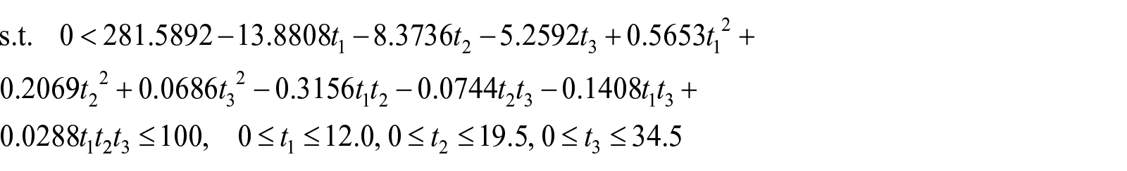
The results of the aforementioned optimization study are summarized in Table 9.
Optimization results for six possible sequences of multilayer modules.
BPP: ballistic performance parameter.
The optimal sequences are highlighted in bold letters.
Optimization results show that the first and third sequences perform better than other sequences. Optimization study is repeated for
Results of ballistic experiments on multilayer module for the sequence Armox/Ti/Al: (a) front layer 5.5 mm Armox-500T, (b) middle layer 8.5 mm Ti-6Al-4V and (c) back layer 13 mm Al-2024.
Results of ballistic experiments on multilayer module for the sequence Ti/Armox/Al: (a) front layer 8.5 mm Ti-6Al-4V, (b) middle layer 5.5 mm Armox-500T and (c) back layer 13 mm Al-2024.
Results of ballistic experiments on multilayer module for the sequence Al/Armox/Ti: (a) front layer 13 mm Al-2024, (b) middle layer 5.5 mm Armox-500T and (c) back layer 8.5 mm Ti-6AL-4V.
Results of numerical simulations on multilayer module 5.5 mm Armox-500T, 8.5 mm Ti-6Al-4V and 13 mm Al-2024 thicknesses: (a) Armox/Ti/Al, (b) Ti/Armox/Al (c) Al/Armox/Ti.
Comparison of experimental results with numerical simulations for optimal multilayer modules.
BPP: ballistic performance parameter.
The weight efficiency and thickness efficiency of the optimal module are compared with individual material in Figure 14. It is clear that weight-wise composite module performs better compared to Armox-500T and Al-2024, whereas its performance is almost the same when compared to Ti-6Al-4V. Thickness efficiency wise, the composite module is better than Al-2024, inferior to Armox-500T and almost equal to Ti-6Al-4V. The projectile motion in the multilayer module is compared in terms of projectile velocity and deceleration with individual materials in Figure 15. The projectile experiences maximum resisting force initially while travelling through the front layer of Armox-500T in the composite module. The magnitude of this resisting force drops slowly to a lower value when the projectile travels through the middle layer of Ti-6Al-4V. After crossing the middle layer, the projectile velocity drops to zero under a constant resisting force of lower magnitude in the back layer of Al-2024.
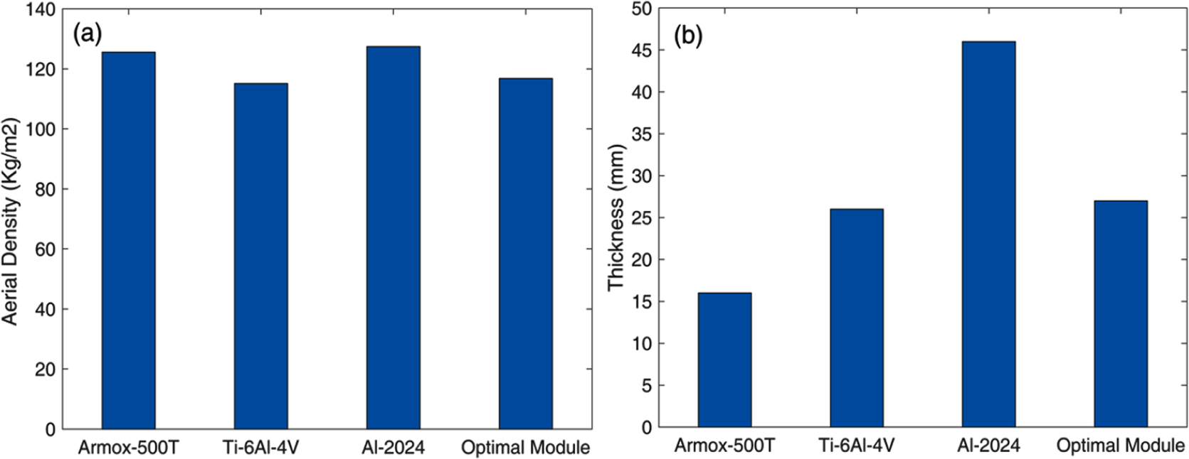
Comparative performance of individual materials and composite module in defeating 7.62AP projectile in terms of (a) aerial density and (b) thickness.
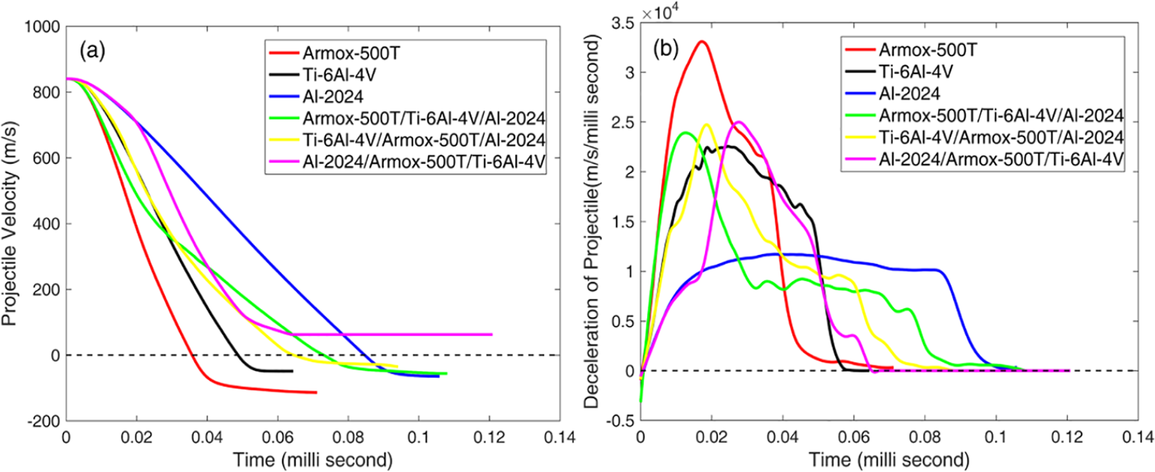
Plots of (a) projectile velocity and (b) deceleration with time during penetration for critical thicknesses 16 mm Armox-500T, 26 mm Ti-6Al-4V, 46 mm Al-2024 and optimal multilayer module (5.5 Armox, 8.5 Ti-6 and 13 mm Al-2024).
Summary and conclusion
Efficient and lightweight armour structures can be built by combining potential armour materials in different layers of a multilayer armour module. The performance of these multilayer armour modules is affected by the position and thickness of the individual layers. This work presents and tests a methodology to find the optimal sequence and thicknesses of different material layers in a composite armour module. The methodology is demonstrated with application to three materials: Armox-500T, Ti-6Al-4V and Al-2024 against 7.62 AP projectile. The first step is to develop an accurate numerical model for ballistic impact behaviour of an individual material. Detailed description of material behaviour at higher strain rates and temperature forms the core of numerical models. The material parameters for models like Johnson–Cook strength and failure models used to describe material behaviour in such impact events can be evaluated using laboratory-scale experiments on setups like Split–Hopkinson pressure bar (SHPB). After experimental validation of numerical models for individual materials, a set of numerical simulations is performed using the DOE approach to generate response surface for ballistic performance of the multilayer module. RV is a better measure of ballistic performance in the case of complete penetration or perforation of the target while DOP is a better measure in the case of partial penetration. A bullet may completely or partially penetrate a target for different thicknesses of material layers. Therefore, a new BPP (defined in equation (4)) is introduced by normalizing these two quantities to bring uniformity between two cases of complete and partial penetration. This parameter combines both the ballistic performance measures; thus, BPP provides more information regarding ballistic performance of a target compared to RV and DOP. After generating the response surface for BPP in different sequences, optimization study is carried out to find the best sequence and thicknesses of individual material layers.
The proposed optimization scheme is validated with ballistic experiments to defeat 7.62 AP projectile. The sequence Armox-500T/Ti-6Al-4V/Al-2024 with thicknesses 5.5, 8.5 and 13 mm is found to be the best after scrutinizing the results of optimization scheme and ballistic experiments. A strong agreement is observed between the predictions of optimization scheme and ballistic experimental results. Therefore, the proposed scheme is suitable for optimal design of the multilayer armour module. The comparative performance of individual materials with the optimal multilayer module reveals that the selected composite module offers advantages in terms of weight efficiency over Armox-500T and Al-2024 and is found to be thickness efficient over Al-2024. It should be noted that we optimized the composite module against full charge velocity of 7.62 AP projectile. The deformation/failure response of a target varies with varying impact velocities. But experiments were not performed at different impact velocities because of limited experimental resources. However, the proposed optimization scheme can be used to get optimal solution for any impact velocity. To ensure full-proof protection capability of the designed module, it can be tested for its BLV to check its performance at different impact velocities.
Ballistic impact experiments are expensive and require longer time in general to ensure the consistency of results. Moreover, it is difficult to understand the physical mechanism behind the impact event with few experiments. Our methodology offers advantages over these limitations. The design procedure is easy to implement once the information on individual material is available. It is not restricted to the design of three material layers and can be used to design the armour module with any number of layers. Spacing increases ballistic resistance of multilayer targets in some cases and thus there is a chance of improving the performance of armour module. This study can be further extended for optimal design of the multilayer armour module with spacing between the layers. Another possible extension of this work is to improve the optimization scheme by using artificial neural network (ANN) and deep learning algorithms to handle complex and highly non-linear ballistic response surfaces.
Supplemental Material
Supplementary_Production – Supplemental material for An optimization scheme for a multilayer armour module against 7.62 mm armour piercing projectile
Supplemental material, Supplementary_Production for An optimization scheme for a multilayer armour module against 7.62 mm armour piercing projectile by Ashish Paman, Govindan Sukumar, B Ramakrishna and Vemuri Madhu in International Journal of Protective Structures
Footnotes
Acknowledgements
The authors wish to express their sincere gratitude to the Director, DMRL for granting permission to publish this manuscript. The support of officers and staff of Armour Design and Development Division group is gratefully acknowledged.
Declaration of conflicting interests
The author(s) declared no potential conflicts of interest with respect to the research, authorship and/or publication of this article.
Funding
The author(s) disclosed receipt of the following financial support for the research, authorship and/or publication of this article: The authors thank Defence Research & Development Organization (DRDO) for funding this work.
Supplemental material
Supplemental material for this article is available online.
References
Supplementary Material
Please find the following supplemental material available below.
For Open Access articles published under a Creative Commons License, all supplemental material carries the same license as the article it is associated with.
For non-Open Access articles published, all supplemental material carries a non-exclusive license, and permission requests for re-use of supplemental material or any part of supplemental material shall be sent directly to the copyright owner as specified in the copyright notice associated with the article.