
Abstract
Weak political systems and poor governance in certain developing countries are found to have a war-like environment where structures are being targeted by blasts and bombs. Industrial blasts due to frail know-how and mishandlings are also quite common. Recent accidental explosions like that occurred at the Beirut Port, Lebanon (August 2020); ammunition depot in the outskirt of the Ryazan City of Russia (November 2020) are of concern for the safety of adjacent building infrastructure and their users. Such intense loading events cause damage to certain elements of a structure which may result in disproportionate or progressive collapse. It necessitates a clear understanding of the phenomenon of the blast and extreme loads induced out of it, and response of the target structure under such loadings. In this study, the state of research on air-blast and ground shockwave parameters, shallow underground blasting, and on the ground and buried shallow blast-resistant shelters are presented. The phenomenon of the self-Mach-reflection of the explosion, loading parameters and empirical blast models available in the open literature followed by the damage criteria for the buildings subjected to the underground blasting and available peak particle velocity (PPV) prediction models have been discussed. To make the application of advanced materials such as fibrous concrete, ultra-high performance concrete, FRP composites, etc., it is important to comprehend the existing blast/shock-resistant shelters and their response under such loading. The shelters are primarily designed by incorporating features of the materials like high degree of deformability/ductility, use of the shock-isolation panels and the mechanism for controlling crack formations. Finally, conclusions and recommendations for future studies are summarised. This paper presents prospects to engineers, town planners, researchers, policymakers and members of the core drafting sectional committees to understand the phenomenon of the blast and extreme loads induced out of it.
Keywords
Introduction
Prior to recent explosive-induced havocs particularly in the Beirut City of Lebanon, the blast-resistant design was primarily considered for potentially important structures such as embassies and other military facilities (Alam et al., 2021; Anas et al., 2020b, 2021; Cheaito and Al-Hajj, 2020; UNESCO Statement of Solidarity, 2020). The Beirut blast resulted in a death toll of 200 in addition to injuries to >6000 civilians. Collective infrastructural loss due to damage was estimated to the tune of $10–15 bn. Collapse of the buildings in the vicinity of the blast site and even damage to the structures at far off distances has increased the concern of the structural engineers for the safety of the buildings against blast-induced loading. Another most recent accidental explosion triggered by a sweeping glaze in a nearby field towards the ammunition depot in the Ryazan (Russia) has got artillery shells exploding every 10 s. More than 2300 residents were evacuated from within a 5 km radius of the ammunition depot. It has been noticed that the level of damage to the structure from the blast could range from reparable to collapse leading to the loss of lives (Anas et al., 2020a, 2020c). For the safety of the life and survival of the structures, a section of engineers is of the opinion that the structures in vulnerable (or war) zones should also be considered to design against such extreme loadings.
For the reliable blast-resistant design of structures, it is paramount important to understand the mechanism of blast wave propagation, blast loading characteristics and structural response/damages (Hao et al., 2016). Design approaches given in the current blast standards/manuals are based on the single-degree-of-freedom (SDOF) idealisations and are not suitable to predict structural response/damage under near field or close-in explosion loading where the response of a structure is governed by diagonal or direct shear mode, or governed by localised damage due to reinforcement yielding, material crushing and spalling (Hao et al., 2016). Field tests and numerical simulations are needed to more reliably quantify the response of a structure (Goel and Matsagar, 2014; Hao et al., 2016; Shirbhate and Goel, 2021). Explosion testing is a direct method to study the behaviour of the structure or structural elements. The physical testing results not only demonstrate the response of the structure but also be utilised to validate/calibrate the fidelity of the numerical/analytical models (Hao et al., 2016). However, field testing is often difficult to perform, not only because it is often restricted due to safety consideration, but also because it requires expensive and highly specialised equipment and instrumentation skills to capture and record such explosive-induced extreme loading and structural responses/damages (Goel and Matsagar, 2014; Hao et al., 2016). With the advancement of computer technology and computational mechanics techniques, several high-fidelity FEM-based commercial software packages have been developed and widely utilised to simulate the non-linear blast response of a structure. It is a common practice now to use a validated numerical model for further investigation of the structure subjected to the blast loading (Hao et al., 2016). Numerical or finite element simulations provide more detailed visualisations of the results which are not possible in the field tests. However, such simulations can only be used after the model is validated (or calibrated) to give reliable or more accurate predictions.
Figure 1 shows the various ranges of blast peak overpressure (POP) corresponding to detonation distances along with expected damage caused due to explosive-induced blast loading. It can be seen from Figure 1 that in the nearest range where the blast pressure is approximately 1373 × 10−3 MPa, the air-blast wave generated from the explosion can inflict serious injuries to humans resulting in loss of life. As the detonation distance increases, the blast pressure decreases as well. Air-blast pressure of magnitude 245 × 10−3 MPa and more can cause Pneumothorax (i.e. the collapse of the lungs) whereas, 98 × 10−3 MPa of peak overpressure can result in the rupture of eardrums. Minor damage in the form of cracking/crushing of concrete can be observed in the blast pressure range, 17.65 ⩽ POP (×10−3 MPa) ⩽ 30.40. Heavy damage in the form of rupturing of reinforcement, failure of critical components such as columns, beams, etc., can be seen in the peak overpressure range, 64.70 ⩽ POP (×10−3 MPa) ⩽ 98. In the extreme case of high blast pressure at least detonation distance, the air-blast wave can cause irreparable damage to the structure or components and may result in progressive structural collapse.
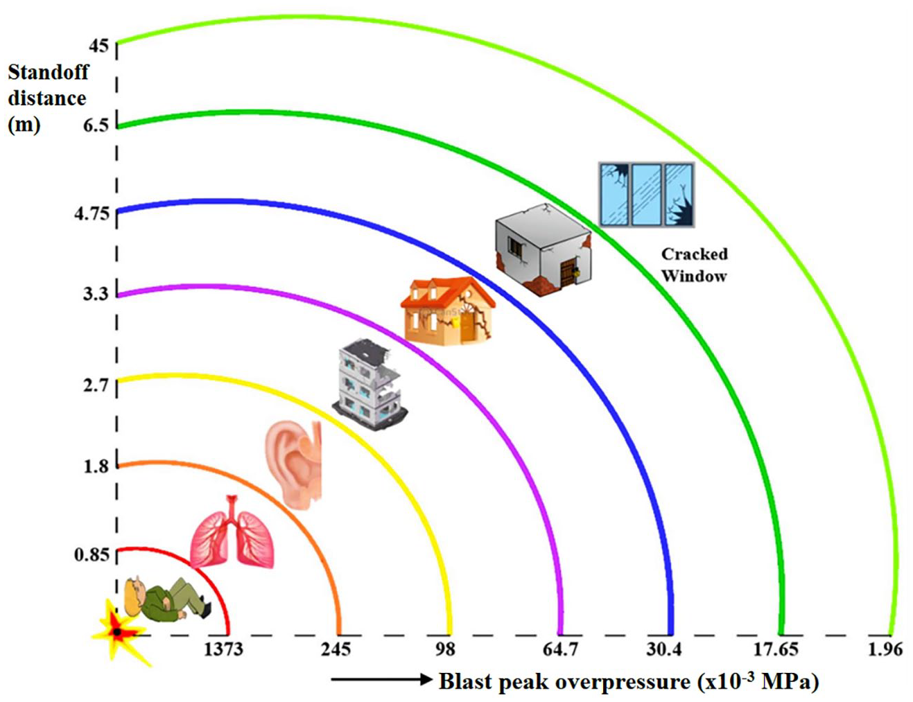
Expected damage caused by air-blast wave corresponding to peak overpressure ranges and respective standoff (or detonation) distances (Goel and Matsagar, 2014).
Explosives that may be considered in the structural design include improvised explosive devices (IEDs 1 ), standoff IEDs, people-borne IEDs, vehicle-borne IEDs, military weapons (i.e. aerial bombs) and conventional explosives (TNT/ANFO/RDX/Semtex), which are being increasingly employed to trigger blasts around the world (Goel and Matsagar, 2014; TM 5-1300, 1990; UFC 3-340-02, 2008). When such explosives are misused to blast buildings, consequences are found to be extremely devastating not only to the building structure but also to the users of the building making them suffer from grievous injuries sometimes fatal to their lives. Both explosives and blasts are categorised as small (WTNT ⩽ 5.00), medium (5.00 < WTNT ⩽ 20.00), large (20.00 < WTNT ⩽ 100.00) and very large (WTNT > > 100.00), where WTNT is the weight of the TNT explosive in ‘kg’ (Goel and Matsagar, 2014; UFC 3-340-02, 2008). Blast-induced impulsive load occurs for a very short duration (microseconds to milliseconds) with high amplitude, which results in different structural responses/damages as compared to other quasi-static and less intense dynamic loads such as those induced by wind, wave and earthquake (Goel and Matsagar, 2014). Furthermore, the response of a structure and its materials under such extreme loadings are generally non-linear, involving complex stress states and are time-dependent rendering available design practices in the current design standards/manuals not necessarily lead to the reliable prediction of the structural response (Hao et al., 2016). Blast engineering being a specialised field of structural engineering, most of the structural engineers are little aware of the phenomenon of the blast, blast loading and response of the structures subjected to the blast (Anas et al., 2021a; 2021b; 2021c; 2021d; 2021e; 2021f). In the present study, it is attempted to provide a detailed review of the blast loading on structures and blast-resistant shelters that could be useful for structural engineers and sectional committee members responsible for drafting the blast design standards/manuals.
The blast environment
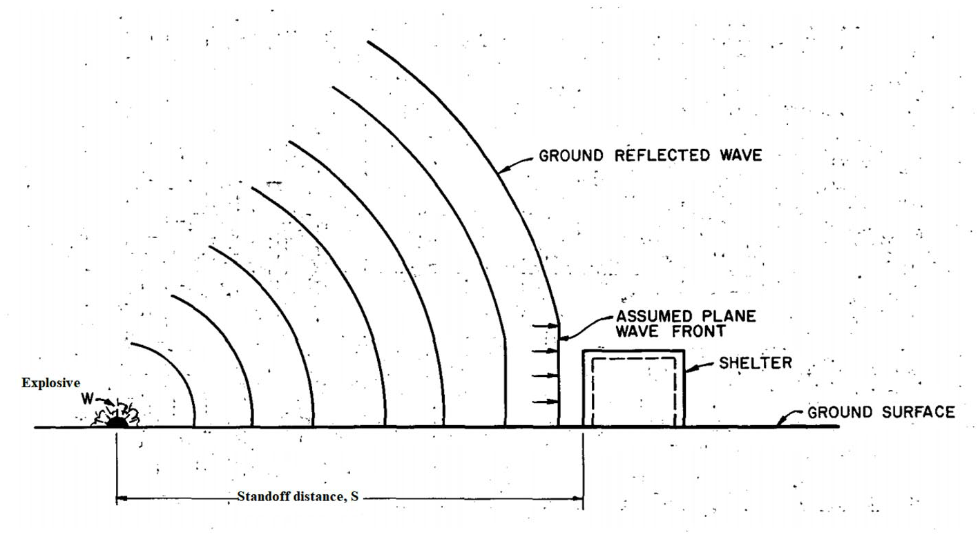
To design a structure, the designers are supposed to understand the intended loads the structure would carry during its lifespan. Blast loading was assumed to be rarely acting on the structure, however, in the current scenario prevailing almost all over the world, structures are subjected to blast loading more frequently and this is why it seems necessary to understand the phenomenon of blast and loads induced by it. The blast loading comprises air-blast pressure, ground shock and primary/secondary fragments impact, particularly in the near-field or close-in detonations; whereas, in the far-field detonation, structures are subjected to only air-blast pressure (Anas et al., 2020c; Hao et al., 2016; Wu and Hao, 2005). In the case of the free-air burst, 2 a sharp-fronted blast wave forms and propagates outwards from the source of the explosion (Figure 2(a)). When this blast wave strikes the ground surface, it undergoes regular reflection (TM 5-1300, 1990). Thus, two shocks, the incident and the reflected one join at the ground surface (Figure 2(b)). In regular reflection, the flow near the ground surface has a large vertical component. As the blast wave continues to propagate outwards along the ground surface, a shock front known as the Mach stem is formed by the interaction of the incident and reflected waves (UFC 3-340-02, 2008) (Figure 2(c)). Thus, the Mach reflection begins. Some variation of the overpressures over the height of the Mach stem occurs, however, for design purposes, this variation is neglected and the blast is considered as a plane wave (uniform pressure) over the full height of the front. The height of the Mach stem increases as the blast wave propagates away from the point of the explosion (UFC 3-340-02, 2008). This increase in height is referred to as the path of the triple point which is formed by the intersection of the incident, reflected and Mach waves (Figure 2(c)). In the surface burst, 3 the only shock forms may be thought of as a combination of the incident and reflected waves having the flow almost parallel to the surface to strike the on-the-ground target (Figure 3) (IS 6922, 1973; Shirbhate and Goel, 2021; TM 5-1300, 1990; UFC 3-340-02, 2008).
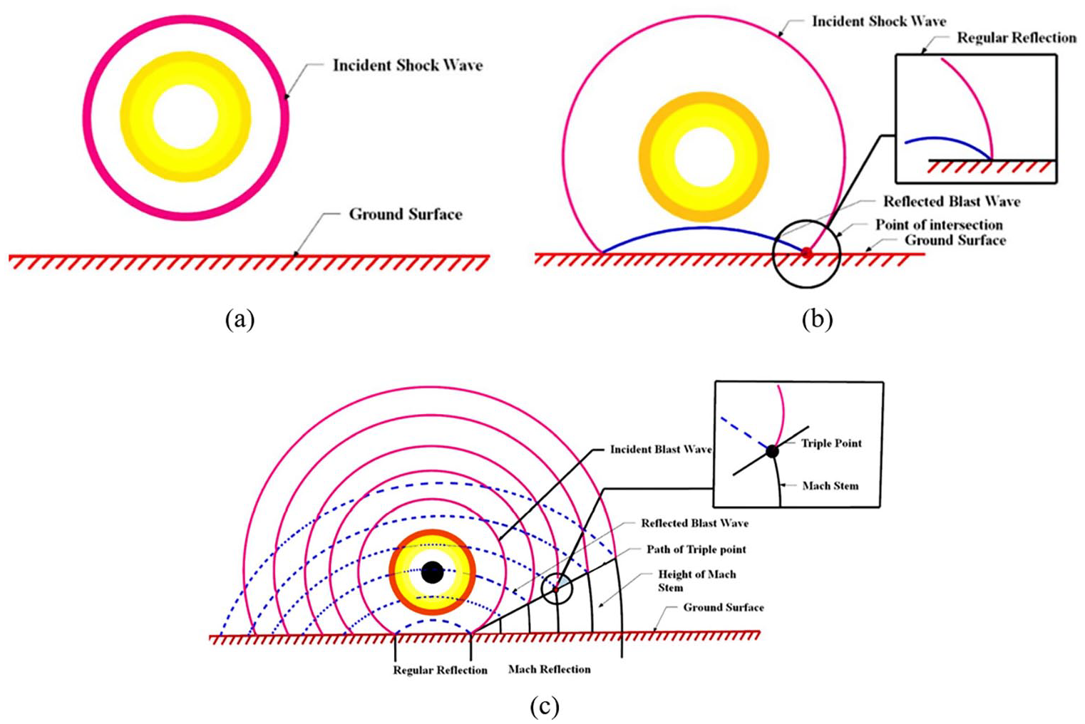
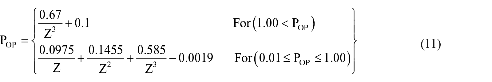
Air-burst blast environment: (a) incident shock wave, (b) regular reflection and (c) mach reflection (Goel and Matsagar, 2014; TM 5-1300, 1990; UFC 3-340-02, 2008).
Surface-burst blast environment (TM 5-1300, 1990; UFC 3-340-02, 2008).
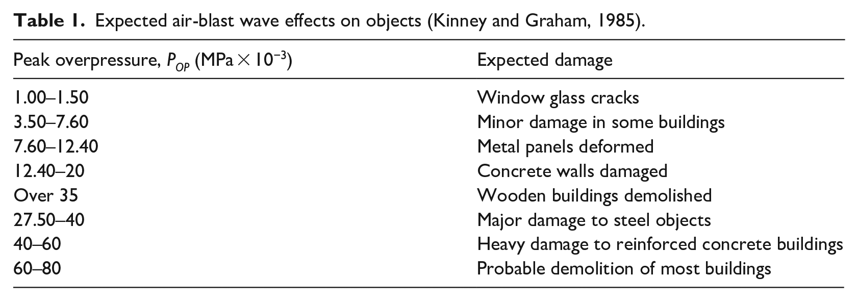
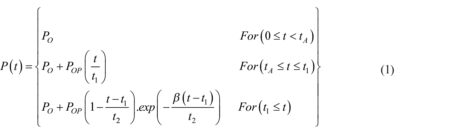
Figure 4 shows the idealised explosive-induced pressure wave profile, along with different loadings in relation to amplitude and frequency (Goel and Matsagar, 2014; Wu and Hao, 2005). A large amount of energy rapidly releases from explosive-induced detonation that converts the solid or liquid explosive into a very hot, dense, high-pressure gas at high temperatures. A shock front (Mach stem) associated with the high-pressure gas moves radially out from the source of the explosion into the surrounding atmosphere as a strong blast wave, driven and supported by the hot gases (Goel and Matsagar, 2014; UFC 3-340-02, 2008). The Mach front, termed the shock wave, is characterised by an almost instantaneous linear rise from ambient air-pressure (PO) to a peak positive overpressure (POP) (Figure 4) (IS 4991, 1968). The shock front arrives at a given location at a time (tA) and, after the rise to the peak value (POP), the peak overpressure decays to the ambient value in time to which is the duration of the positive phase of the blast (td−). This is followed by a suction phase with a duration, t− that is usually two to five times longer than the positive phase and characterised by a negative pressure (below ambient air-pressure) having a maximum value of PS− (IS 4991, 1968). The negative phase of the blast is usually less important in the blast design of the structures than is a positive phase, and its amplitude PS− must, in all cases, be less than ambient air-pressure, PO (Anas et al., 2020a, 2020b; Goel and Matsagar, 2014; Hao et al., 2016; IS 4991, 1968; TM 5-1300, 1990). It is noted from Figure 4 that the blast-induced loading is associated with very high amplitude and frequency; hence it requires special attention. Table 1 lists the expected effects of air-blast waves on objects under different peak overpressure ranges.
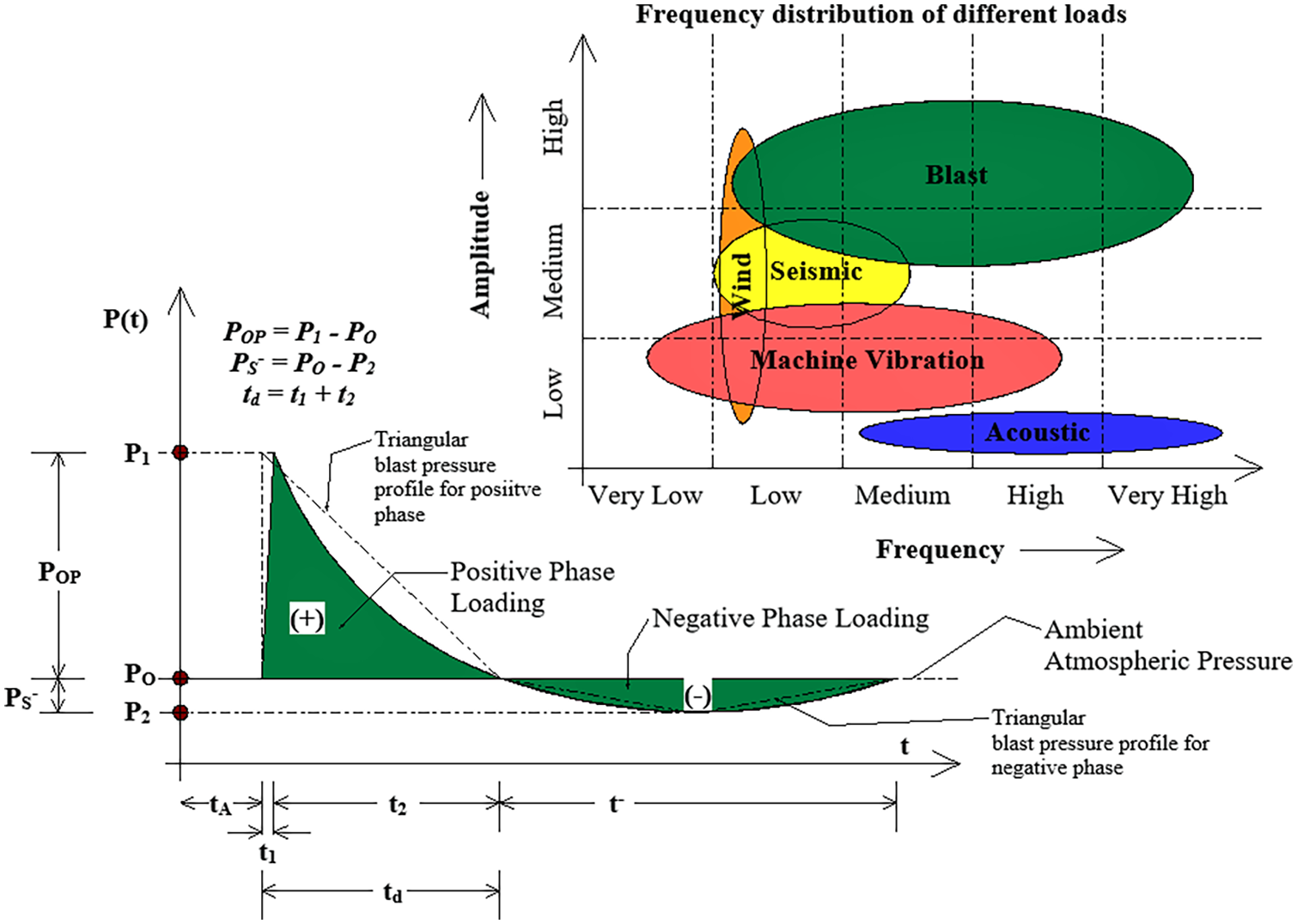
Typical air-blast pressure profile and amplitude-frequency relations of design loadings (Goel and Matsagar, 2014; Wu and Hao, 2005).
Expected air-blast wave effects on objects (Kinney and Graham, 1985).
Structural response
In general, when a sharp fronted shock wave moving parallel to the ground encounters a target structure, it first reflects from the object, subjecting it to a load greater than the incident overpressure (TM 5-1300, 1990). The shock wave then diffracts around the target, subjecting it additionally to loading due to the movement of air particles in the shock wave, a type of loading that is measured by the so-called dynamic pressure, ½ ρu2, where ρ = density and u = particle velocity (UFC 3-340-02, 2008). Eventually, if the shock wave duration is long enough, it subjects the object to so-called drag phase loadings that are composed of the sum of the static overpressure in the shock wave plus a drag loading due to the shock wave dynamic overpressure (Anas et al. 2021a, 2021b, 2021c, 2021d, 2021e, 2021f). Diffraction phase loadings, that is, those that occur during the time taken for the head of the shock wave to pass over the target structure, are usually higher than those that occur during the drag phase, or than those that occur between the time for completion of diffraction phase loadings and the onset of drag phase loadings (the transition phase). The durations of diffraction and transition phase loadings are not greatly affected by the total duration of the shock wave, since they are related to the time for pressure signals to propagate from one part of a building to another (UFC 3-340-02, 2008). Duration of drag phase loading, on the other hand, depends directly on shock wave duration. Overpressure, dynamic pressure, and shock wave duration are all related to weapon size (or explosive weight) and distance from the point of explosion. For two weapons (or explosives) of yield Y1 and Y2, overpressure and dynamic pressure at standoff distances R1 and R2 will be the same if R1/(Y1)1/3 = R2/(Y2)1/3; duration at distance R2 will equal duration at R1 multiplied by (Y2/Y1)1/3 (IS 4991, 1968; UFC 3-340-02, 2008).
Earthquake and blast demands
Figure 5 shows a comparison between a normalised ground motion record from the 1989 Loma Prieta earthquake and a normalised free-field blast overpressure profile generated from the detonation of the high-explosive (HE) charge (Anas et al., 2020c; Duvall and Petkof, 1959; Goel and Matsagar, 2014; Wu and Hao, 2005). The duration of an unconfined blast pulse from HE detonation is generally on the order of microseconds to milliseconds, whereas the strong motion duration of a typical earthquake record is of several seconds or even more. It can be noted from Figure 5 that the cyclic nature of the ground motion acceleration record, which includes multiple peaks (Anas et al., 2020c; Goel and Matsagar, 2014). Conversely, there is an instantaneous amplification for the blast overpressure history followed by a rapid decay to a sub-atmospheric ‘negative pressure’ condition (Goel and Matsagar, 2014). It is very important for engineers to know the difference between the response of buildings to blast and earthquake loadings. Consideration of earthquake loading is rather old, but the blast loading is rather new. Earthquake demand input is generally kinematic in nature, whereas the blast demand input is force-based in nature (Anas et al., 2020c; Duvall and Petkof, 1959).
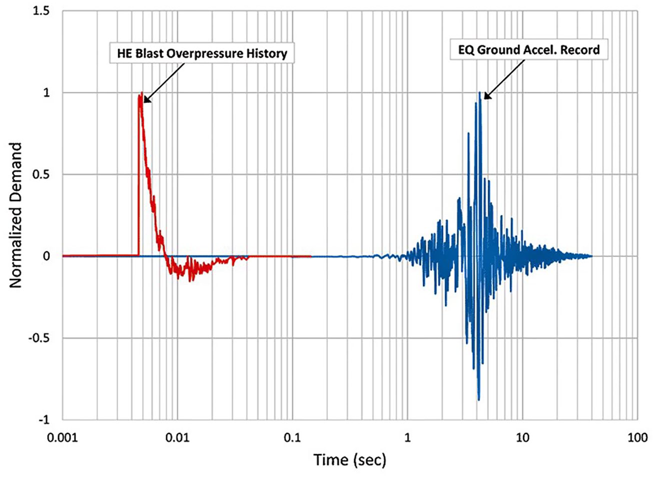
Comparison of typical demand input (Anas et al., 2020c; Duvall and Petkof, 1959; Goel and Matsagar, 2014; Wu and Hao, 2005).
Empirical blast models
Modelling of positive blast phase
Several empirical estimations to predict and model the positive phase of the air-blast have been proposed by many researchers and extensively investigated (Adushkin and Korotkov, 1961; Baker et al., 1983; Brode, 1955; Held, 1983; Henrych and Major, 1979; Hopkins and Bailey, 1998; Kinney and Graham, 1985; Li and Ma, 1992; Mills, 1987; Newmark and Hansen, 1961; Pannill and Kingery, 1964; Smith and Hetherington, 1994; Swisdak, 1994). Wu and Hao (2005) proposed the following empirical-based model to estimate the positive blast phase profile.
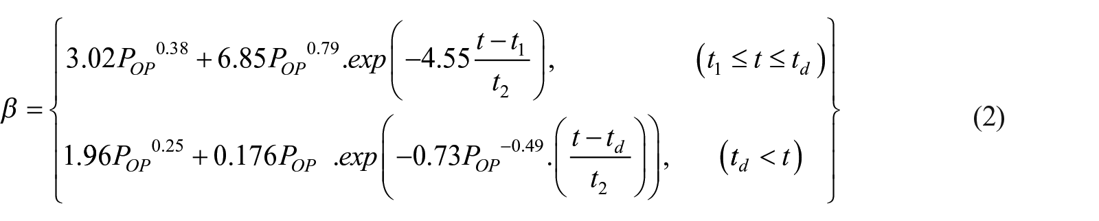
Here, P(t) = air-blast pressure at time ‘t’; PO = ambient air-pressure (≈0.10 MPa); POP = peak positive overpressure (MPa); tA = time of arrival of shock wave (s); t1 = rising time duration (s); t2 = decreasing time (s) and β = decay coefficient. The decay coefficient (β) can be computed using the following equations (Wu and Hao, 2005).
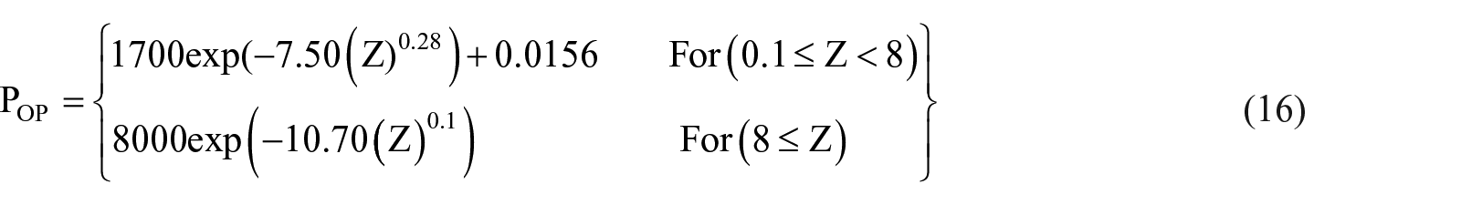
for POP (MPa) ≤ 1.0,
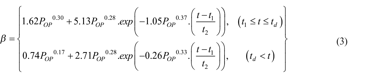
for 1 < POP (MPa) ⩽ 100. It should be noted that td (s) in the above equations is the duration of the positive phase of the air-blast and can be given as in equation (4)

Other widely used empirical model to compute the air-blast pressure is the Conventional Weapons Effects Program (CONWEP) 2.00 code (CONWEP 2.00, 1991), developed by the U.S. Department of the Army, proposed by Kingery and Bulmash (1984). The blast pressure is calculated using the following empirical relationship.
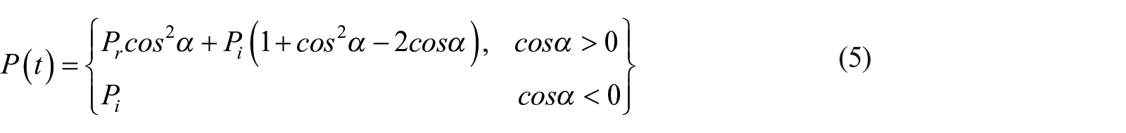
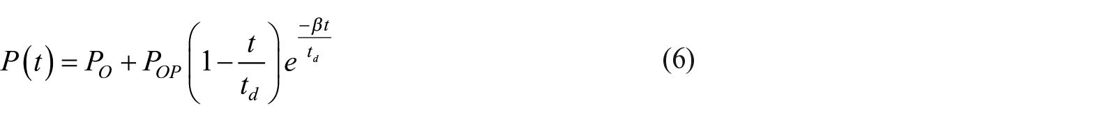
Where, Pi and Pr are the incident and reflected blast pressures, and α is the angle of incidence. The Weapon Effects CONWEP 2.00 code provides the user with a peak blast pressure and impulse that can be used to simulate the blast response of the structure or structural elements (Goel and Matsagar, 2014). Friedlander’s empirical-based model can also be used to compute the positive phase of the air-blast. The original Friedlander’s model is independent of the ambient air-pressure, PO (Dewey, 2018; Goel and Matsagar, 2014). However, the modified Friedlander’s empirical model (with ambient pressure) is also widely considered to model the positive phase, given as in equation (6).
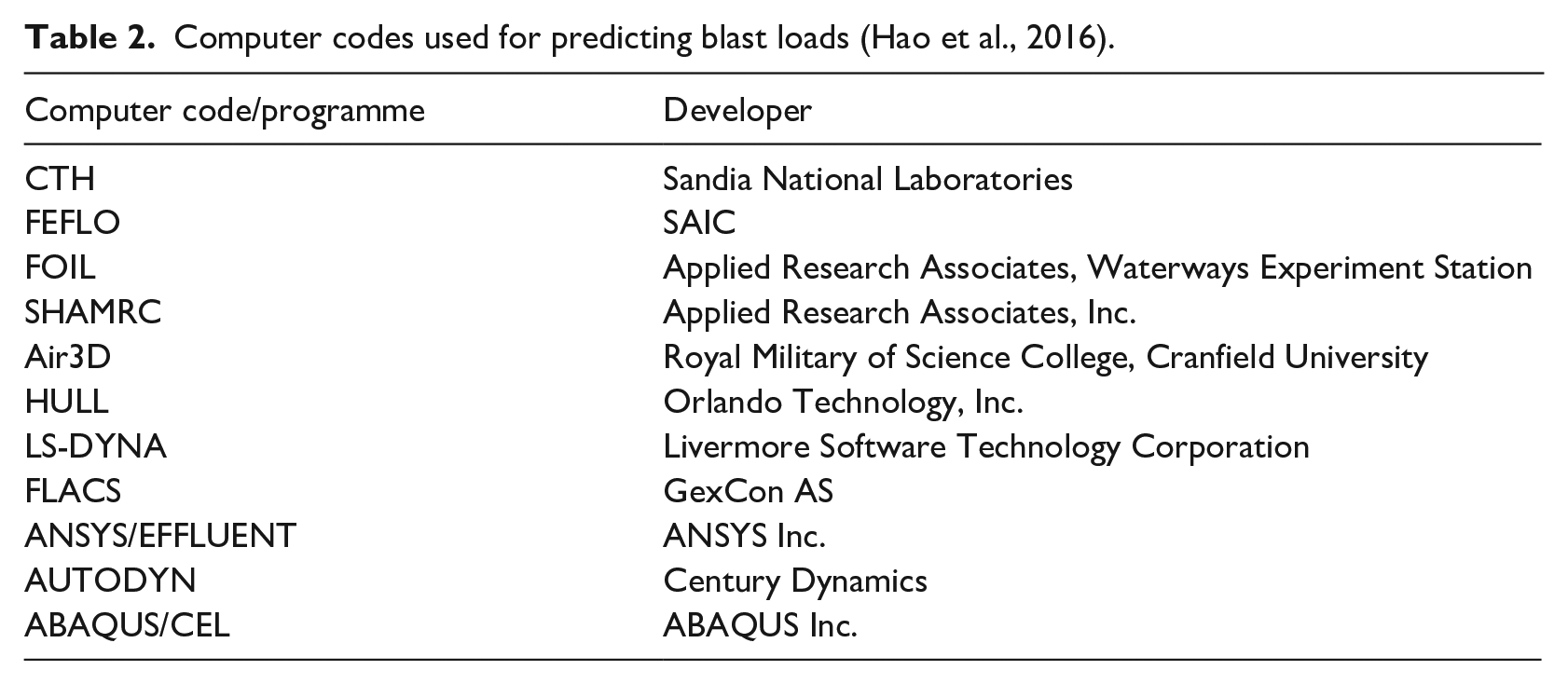
Other methods use the fully coupled Eulerian-Lagrangian (CEL), smoothed particle hydrodynamics (SPH) and smoothed particle hydrodynamics coupled with finite element method (FEM-SPH) techniques to develop explicit blast profiles and simulate the air-blast response of the structure or structural elements (Anas et al., 2021; Goel and Matsagar, 2014; Hao et al., 2016). The results obtained through these techniques are highly dependent on element type, mesh size and their accuracy varies with the method of coupling and also the time step (Goel and Matsagar, 2014). Therefore, mesh convergence must be performed to obtain reliable results prior to the analysis of the structures. Table 2 lists the computer codes used for simulating the blast response of the structure or structural components. While most of these codes are restricted from public release, however, commercially available and most widely used finite element programmes include LS-DYNA, AUTODYN, ABAQUS/CEL and Air3D (Anas et al., 2021; Hao et al., 2016).
Computer codes used for predicting blast loads (Hao et al., 2016).
For a specific shape of the reactive material, the effects of the energy output relative to that of TNT of similar shape can be expressed as a function of mass-specific energy of various materials as follows (Hao et al., 2016; TM 5-1300, 1990; UFC 3-340-02, 2008):

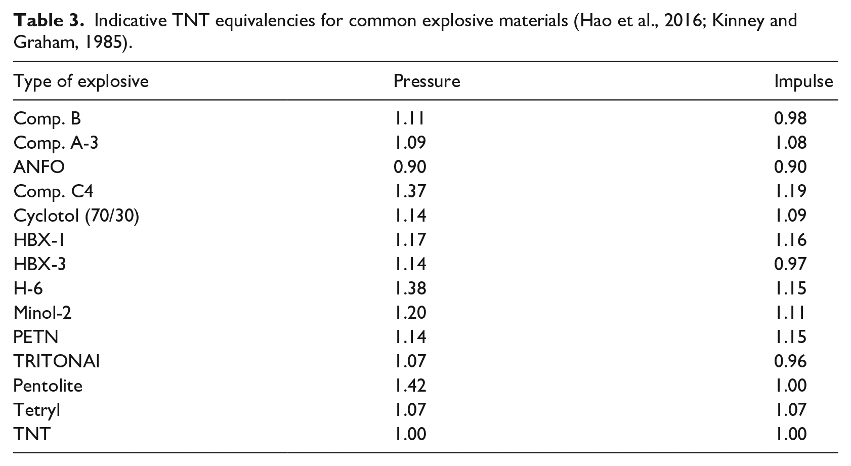
Where WE is the effective charge weight (kg TNT), WX is the weight of a particular explosive (kg), SX is mass-specific energy of the particular explosive (kJ/kg) and STNT is mass-specific energy of TNT (≈4520 kJ/kg). Table 3 gives some indicative TNT equivalencies of selected explosives for pressure and impulse. To describe the integrated effects of the explosive charge (W) expressed in kilograms (kg) and standoff distance (S) expressed in metres (m), the proximity factor or the scaled distance is defined as in equation (8).

Indicative TNT equivalencies for common explosive materials (Hao et al., 2016; Kinney and Graham, 1985).
Modelling of partial vacuum phase (or negative phase)
In the partial vacuum phase of the air-blast, the blast pressure goes below the ambient air-pressure (PO) to the ma*ximum negative pressure or under pressure (PS−) (Hao et al., 2016; TM 5-1300, 1990; UFC 3-340-02, 2008). The amplitude of maximum negative overpressure, PS− is much smaller than the peak positive overpressure, POP. However, the duration of the negative phase is usually two to five times that of its positive pressure phase (IS 4991, 1968). Following different empirical equations to model the negative or suction pressure phase of the air-blast in the units of megapascal (MPa) are:
(a) Brode (1955)
(b) Larcher (2008)
Air-blast wave parameters
Typical air-blast wave parameters are: blast peak overpressure (POP), arrival time of shock/blast wave (tA), positive phase duration (td), underpressure (PS−) and the duration of negative blast phase (t−). Several empirical equations have been proposed by several researchers to estimate the air-blast parameters based on the analysis of large sets of experimental data at different scaled distances. These equations are presented in the following sub-sections.
Peak overpressure, POP
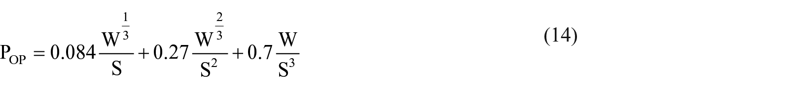
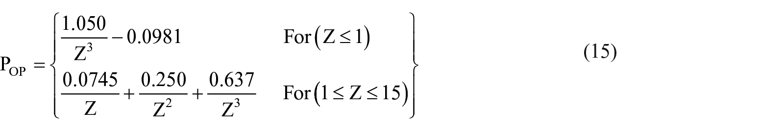
There exist different empirical relations proposed by various researchers to predict the positive peak overpressure, POP. The focus has been given to the important, and widely used empirical equations. These equations have been modified to have the unit of megapascal (MPa), while the standoff distance (S) is expressed in ‘m’, explosive weight (W) in ‘kg TNT’ and scaled distance (Z) in ‘m/kg1/3’.
(a) Brode (1955)
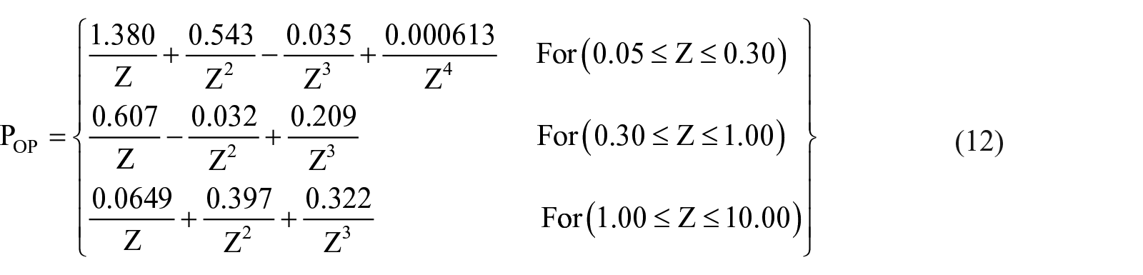
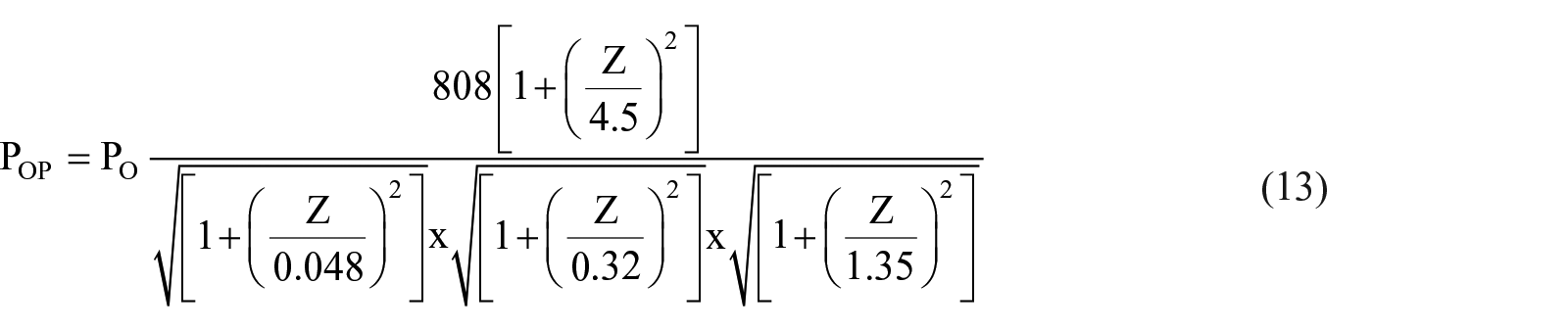
(d) Li and Ma (1992)
Shock wave arrival time, tA
The empirical equations for the blast wave arrival time (tA) are not commonly available and are not usually incorporated in most of the research. All relationships presented have been modified to have the unit of milliseconds (ms).


(c) Ahmad et al. (2014)
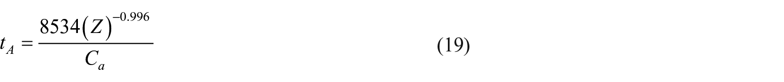
Here, Ca = speed of sound in air (340 m/s), S = standoff distance (m), W = yield of explosive (kg TNT) and Z = scaled distance (m/kg1/3).
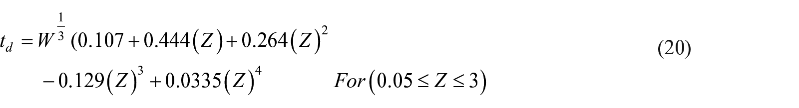
Positive blast phase duration, td
The duration of the positive blast phase (td) might be defined as the time difference between the passing of the Mach stem (pressure front) generated from the explosive-induced detonation and the passing of the end of the positive phase of the air-blast wave pressure profile (TM 5-1300, 1990; UFC 3-340-02, 2008). Several empirical relationships given by different researchers to predict the duration of the positive phase of air-blast wave (td) are listed in this section, and these relationships are modified to have the unit of milliseconds (ms).

(c) Sadovskyi (2004)


Here, S = standoff distance (m), W = explosive weight (kg TNT) and Z = scaled distance (m/kg1/3).
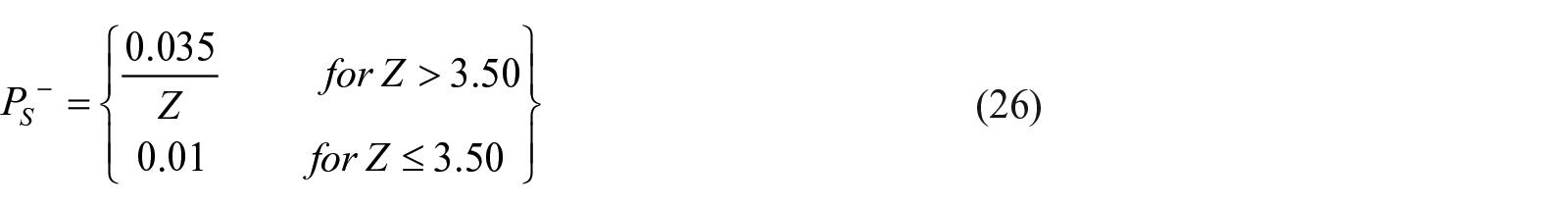
Maximum negative blast pressure, PS−
The pressure front is followed by a rarefaction wave. It follows from its nature that:

Where, PO is the ambient air-pressure. Following are different empirical equations to predict maximum negative blast pressure (

(b) Larcher (2008)
Negative phase duration, t−
The duration of the negative blast phase (t−) might be defined as the time duration in which the air-blast pressure, P(t) falls below the ambient pressure (PO) and then returns to the ambient pressure. The negative blast phase duration (t−) can be calculated using the following empirical relationship proposed by Cabello (2011):

Explosive-induced ground shock
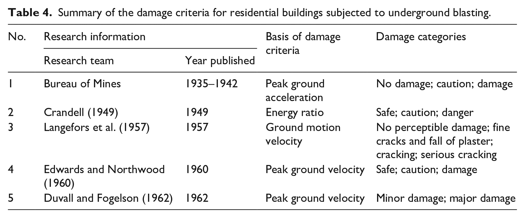
Ground shock generated from the surface burst (or rock blasting) are becoming a particular concern as they can cause severe damage to the building or components. In practice, this damage is controlled by the building authorities through various rules and regulations such as restricting the peak particle acceleration (PPA) or velocity (PPV) (IS 6922, 1973; Jayasinghe et al., 2019; TM 5-855-1, 1986). However, these vibration restrictions are not always valid, as they depend on the dynamic properties of the building and also on the geological conditions of the site. Various experimental site-specific investigations have been conducted by several researchers to predict the ground motion amplitudes (PPV and PPA) due to surface burst or underground blasting (Ambraseys and Hendron, 1968; Crandell, 1949; Duvall and Fogelson, 1962; Edwards and Northwood, 1960; Hao and Wu, 2001; IS 6922, 1973; Jayasinghe et al., 2019; Kahriman, 2004; Khandelwal and Singh, 2007; Kumar et al., 2016; Langefors and Kihlstrom, 1978; Langefors et al., 1957; Monjezi et al., 2011; Nateghi, 2011; Siddiqui and Ahmad, 2007; Wu et al., 1998, 2003).
Crandell (1949) examined the effects of ground vibration due to blasting on structures and presented the damage criteria for the residential buildings based on vibration levels in the ground. Vibration levels were specified in terms of energy ratio (ER), which he defined as
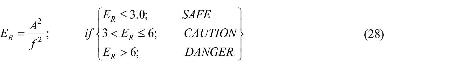
Where, A is the acceleration expressed in ft/s2, and f is the frequency expressed in Hertz (Hz). Langefors et al. (1957) developed another set of damage criteria based on ground motion velocity at the location of the structure. They conducted series of test and labelled the damages into four categories: (1) 0.07 m/s (2.80 in/s), no perceptible damage; (2) 0.11 m/s (4.30 in/s), fine cracks and fall of plaster; (3) 0.16 m/s (6.30 in/s), cracking and (4) 0.23 m/s (9.10 in/s), serious cracking. Figure 6(a) shows the displacement-frequency relations of different damages observed by Langefors et al., where cracking and serious cracking are designated as major damage, fall of plaster and fine cracking are labelled as minor damage, and no perceptible damage is designated as no damage. Edwards and Northwood (1960) specified vibration levels (V. L.) based on ground velocity at the house location, which they described as

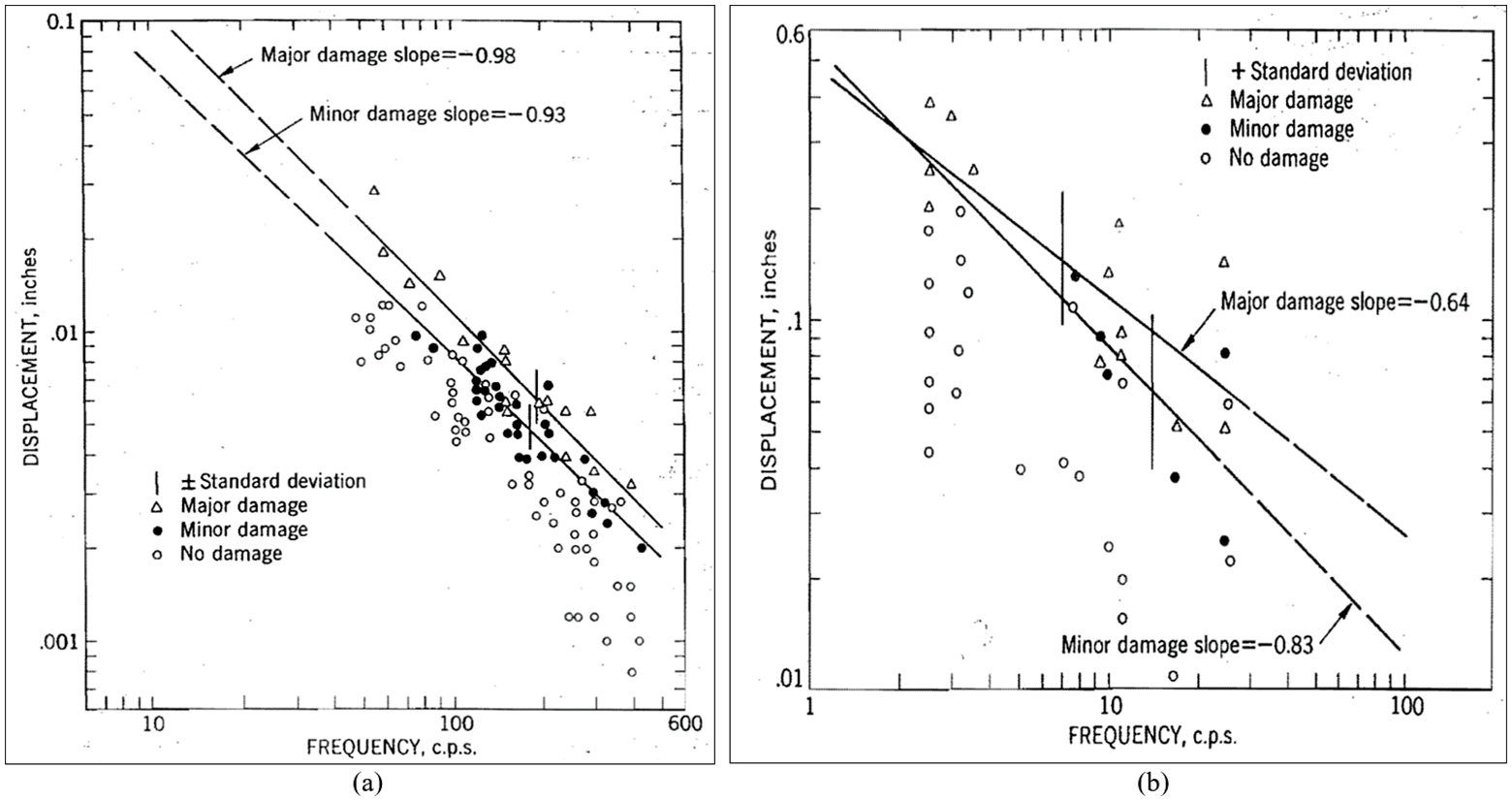
Displacement versus frequency for observed damage by Langefors et al. (1957) (a) and Edwards and Northwood (1960) (b).
Figure 6(b) shows the displacement-frequency relations of different damages noticed by Edwards and Northwood, where major damage corresponds to the fall of plaster and large cracks, and opening of old cracks and fine plaster cracking are labelled as minor damage. Duvall and Fogelson (1962) compared the damage models of Langefors et al. (1957) and Edwards (1959) with the predictions of the Bureau of Mines (Figure 7). The Bureau of Mines, based on peak ground acceleration, labelled the structural damages into three categories: (1) below 0.1g, no damage; (2) between 0.1g and 1.0g, caution; and (3) above 1.0g, damage. Based on the comparison of damage data, Duvall and Fogelson noticed that a peak particle velocity of 0.05 m/s (2 in/s) could be a reasonable value for defining the separation between the safe zone and damage zone. Table 4 summarises the damage criteria for residential buildings subjected to underground blasting. Besides, Pennsylvania (USA) adopted a displacement of 25.40 mm (0.03 in). as a safe limit against blasting, while Massachusetts and New Jersey (U.S.) specified an energy ratio of 1.0 as the permissible limit (Duvall and Fogelson, 1962).
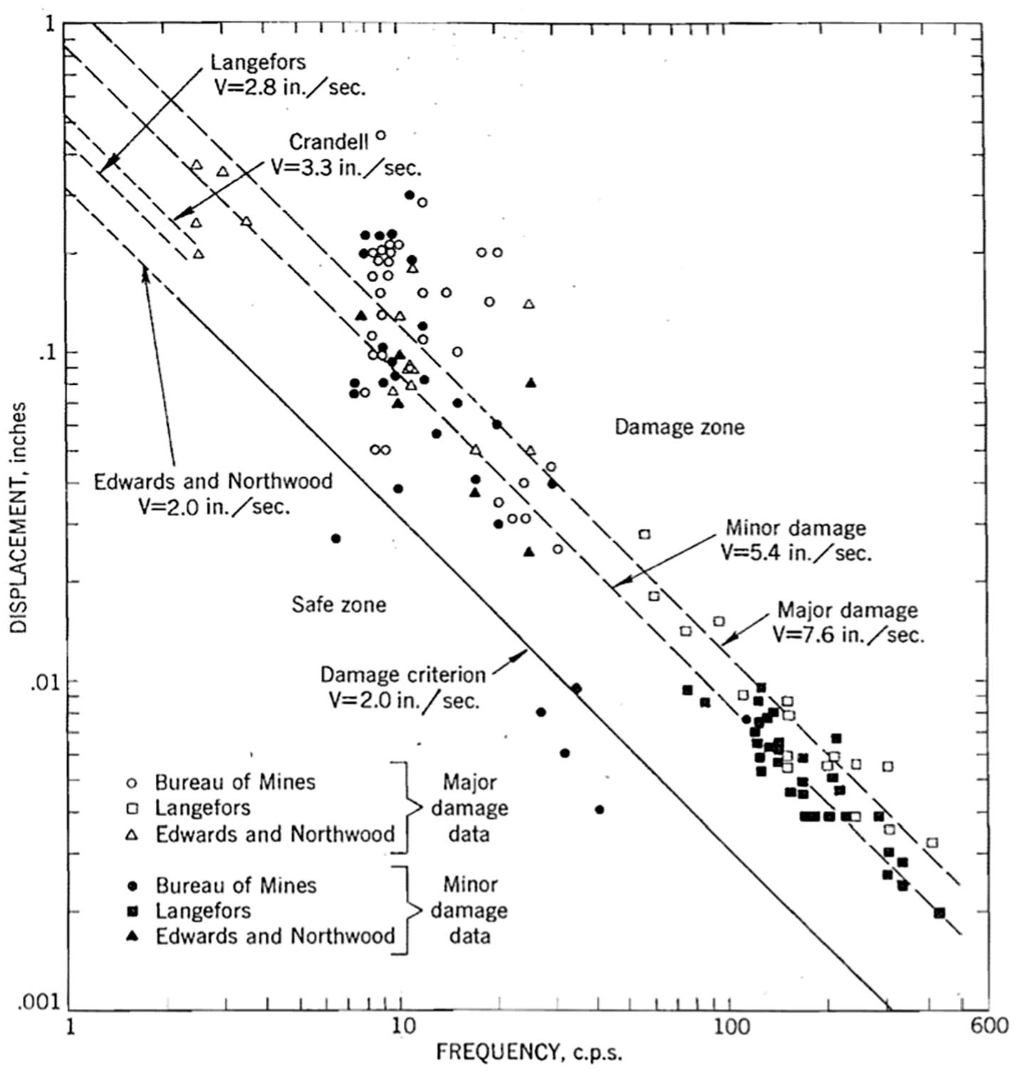
Comparison of observed damages with ‘Bureau of Mines’ (Duvall and Fogelson, 1962).
Summary of the damage criteria for residential buildings subjected to underground blasting.
Typical ground shock parameters are: peak particle acceleration (PPA), peak particle velocity (PPV), arrival time of ground shock (

Where,
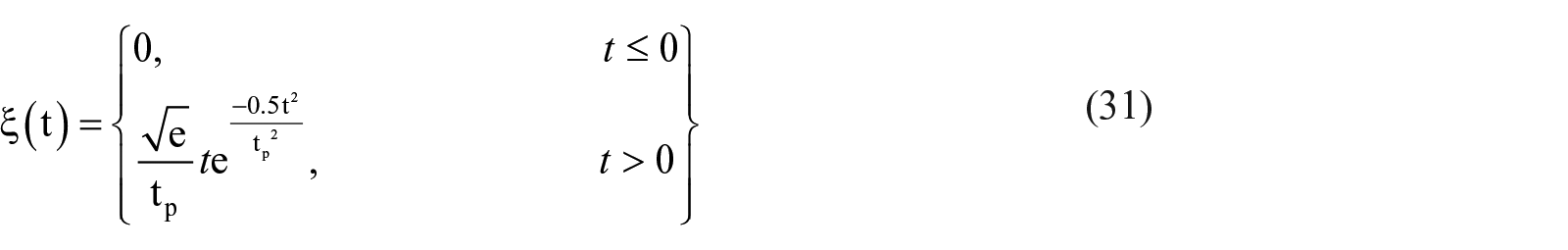

Where, e is the base of the natural logarithm (≈2.72), and tp is the rising time of ground shock (ms). Wu and Hao (2005) based on analysis of large set of experimental data, proposed the following empirical relationships to compute ground shock wave parameters. The results of these equations were compared and found to be in good agreement with the predictions of TM 5-1300 (1990).


Siddiqui and Ahmad (2007) investigated the simultaneous effect of air-blast and ground shock on structures and derived the following empirical equations to predict the ground shock wave parameters.


Here, PPA = peak particle acceleration (g);
Shallow underground blasting: An abridged review
A summary of different empirical-based PPV prediction models proposed by various researchers for different rock sites is listed in Table 5. These site-specific empirical relationships cannot be generalised for use at other sites (Kumar et al., 2016). Though there is a significant scattering of blast data of researchers, each model gives a fair prediction of PPV values at the corresponding site (IS 6922, 1973; Kumar et al., 2016). Any available site PPV model does not accurately predict PPV for other sites.
Summary of PPV prediction models proposed by various researchers.
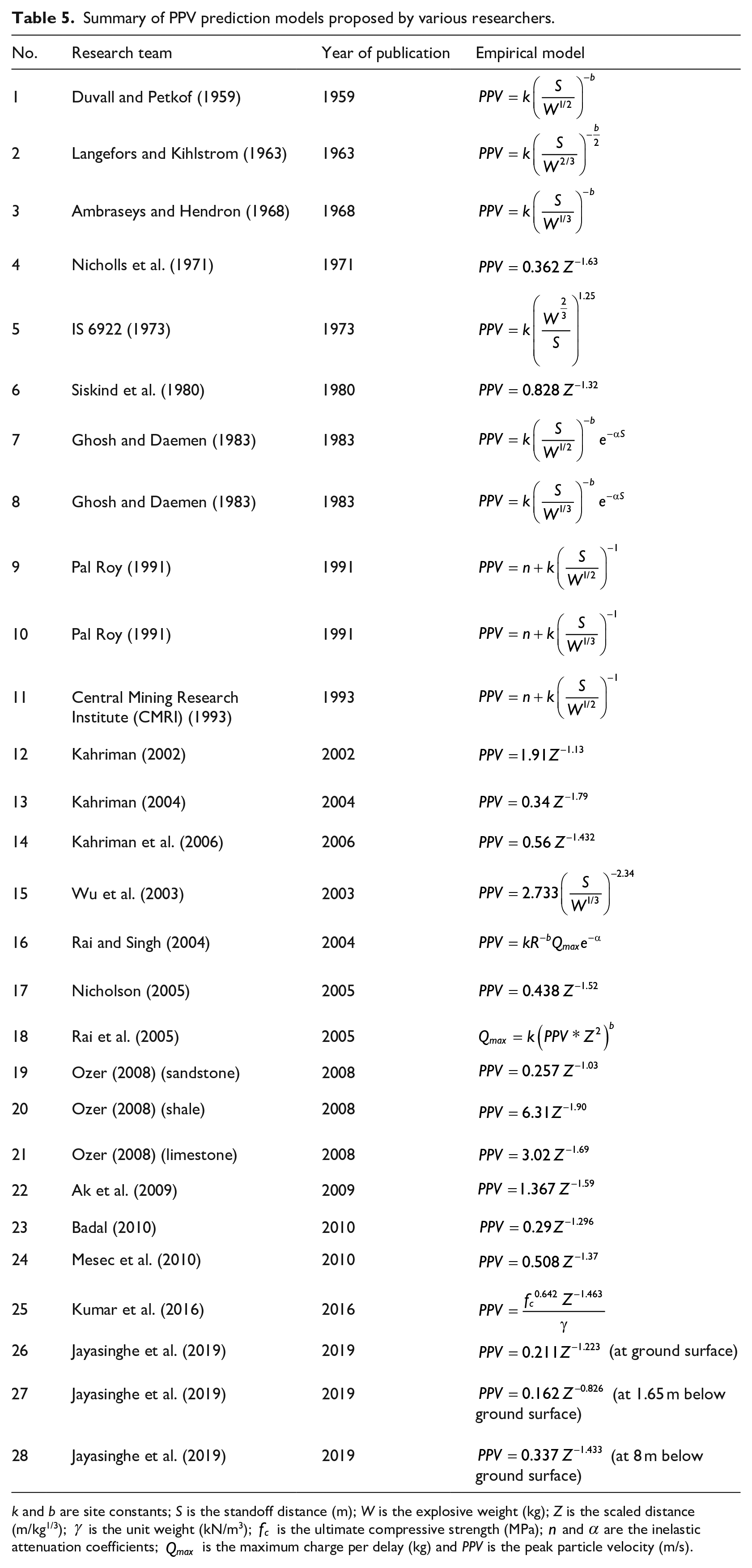
k and b are site constants; S is the standoff distance (m); W is the explosive weight (kg); Z is the scaled distance (m/kg1/3);
Wu et al. (1998)
In this paper, the propagation characteristics of explosive-induced shock wave generated from the cylindrical-shaped explosive in a jointed rock mass were investigated and monitored. Three tests were performed with the explosive charges of 10, 20 and 40 kg TNT, corresponding to the mass density of 5, 10 and 20 kg/m3, respectively. The values of peak accelerations were found to be in good agreement with the available testing data (Cheaito and Al-Hajj, 2020). The values of peak particle velocity (PPV) were 30%–50% smaller than those computed using Dowding’s relationship (Figure 8).
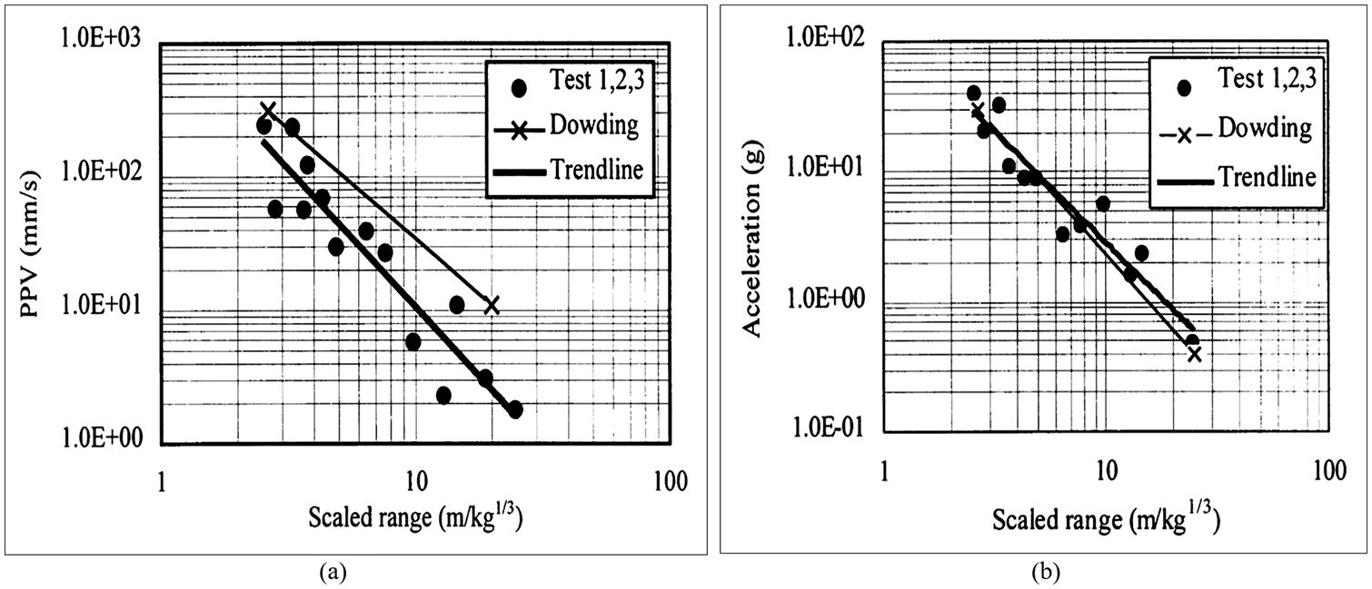
Comparison of results (Wu et al., 1998): (a) PPV versus scaled distance and (b) PPA versus scaled distance.
Hao and Wu (2001)
The authors performed parametric investigation of stress wave propagation produced by various rock blasting conditions in a granite rock mass using validated numerical models, and suggested several empirical equations to predict PPV, PPA and principal frequency (PF) of the stress wave. It was found that charge mass density, explosive distribution pattern and volume/geometry of the charge chamber all affect PPA, PPV and PF of stress wave and damage zones in the granite mass. The damage zones, stress wave PPA and PF were inversely proportional to charge mass density, while PPV was directly proportional to it. At the same mass density, charge chamber volume/geometry affected the damages zones, PF and stress wave PPA, but had little effect on PPV.
Wu et al. (2003)
Wu et al. (2003) conducted a series of large-scale underground blast tests to investigate the stress wave characteristics at the soil-rock interface, on the soil ground surface and in the rock free field; and presented the formulaes to predict stress wave PPV, PPA and PF. Three tests were conducted with the charge sizes of 500, 2500 and 10,000 kg (TNT), corresponding to the mass density of 0.5, 2.5 and 10 kg/m3. They observed that the values of PPV and PPA on the soil ground surface were higher than those obtained at the interface of soil-rock for the same scaled distance range, while for stress wave inside the rock mass, the higher mass density caused higher PPA and PPV but lower PF at the same proximity factor or scaled distance. The values of peak particle velocity were compared and found to be in reasonable agreement with the predictions of Dowding (1996).
Khandelwal and Singh (2007)
In this study, the authors executed a series of blast tests to predict the peak particle velocity (PPV) at a magnesite mine located in the Himalayan region of India and compared their results with those computed using Artificial Neural Network (ANN) technique and several published empirical equations. Empirical formulaes proposed by Ambraseys and Hendron (1968), USBM (Duvall and Fogelson, 1962), Langefors et al. (1957), and IS 6922 (1973) were considered for the comparison of PPV. They noticed that the measured PPV values were in good agreement with those predicted by ANN as compared to other predictors (Figure 9).
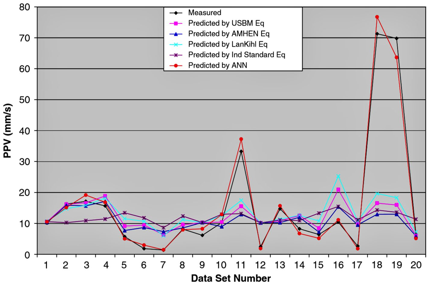
Comparison of predicted PPVs with ANN predictions (Khandelwal and Singh, 2007).
Siddiqui and Ahmad (2007)
Siddiqui and Ahmad (2007) experimentally studied the cumulative effects of ground shock and air-blast pressure generated from spherical shaped charges placed at varying standoff distances (between 5 and 25 m) and presented several empirical relationships to compute blast wave parameters such as peak overpressure, arrival time of shock wave, positive phase duration, normal peak reflected pressure, PPA, the arrival time of ground shock and the time lag between ground shock and air-blast pressure. The results of the proposed empirical equations were compared and found to be in close agreement with those obtained by Brode (1959); Henrych and Major (1979); and Wu et al. (2005) (Figure 10(a)). It was found that the values of PPA in saturated sandy clay were higher than those computed by Wu and Hao (2005) in the rock mass (Figure 10(b)).
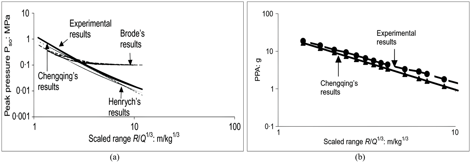
Comparison of results (Siddiqui and Ahmad, 2007): (a) peak overpressure and (b) PPA against scaled distance.
Kumar et al. (2016)
The authors, based on a large number of published blast data, developed two empirical models to predict PPV, one between rock quality designation (RQD) and uniaxial compressive strength (UCS) and another between geological strength index (GSI) and uniaxial compressive strength (UCS). It was concluded that the proposed models could be used with reasonable confidence up to a scaled distance of 80 m/kg1/2.
Jayasinghe et al. (2019)
A series of field explosion tests were carried out to investigate the stress wave propagation in a mixed geological media composed of residual soil and granite rock, and the empirical formulaes to predict PPV on the ground surface and at depths of 1.65 and 8 m below the ground level were proposed. It was observed that the soil-rock interface plays a significant role in reducing the intensity of blast-induced ground vibrations. The values of PPV on the ground surface were found significantly smaller than those obtained below the ground level.
General design features to enhance building robustness
The placement of the building on the site can have a major impact on its vulnerability. The shape of the building can have a contributing effect on the overall damage to the structure (Figure 11) (TM 5-1300, 1990; UFC 3-340-02, 2008). Re-entrant corners and overhangs are likely to trap the shock wave and amplify the effect of the air blast. Note that large or gradual re-entrant corners have less effect than small or sharp re-entrant corners and overhangs (UFC 3-340-02, 2008). The reflected pressure on the surface of a circular building is less intense than on a flat building. When curved surfaces are used, convex shapes are preferred over concave shapes. One of the most successful strategies for the protection of building core functions and infrastructure in blast-protection design is dispersal and redundancy (TM 5-855-1, 1986; UFC 3-340-02, 2008). The significant factors, on which the response of a structural element subject to blast forces depends, are the pressure versus time diagram acting on the element, the effective time period of the element, the resistance versus deflection diagram of the element and the maximum permissible deflection (IS 4991, 1968). When the ratio of time duration td, or t−, to the natural period of the element is <0.1, the problem may be considered as an impulse problem taking the area under the pressure versus time curve as impulse per unit area (IS 4991, 1968). In such a case, the shape of the pressure-time curve is not important. The maximum permissible deflection defines the energy absorption capacity of the element which is equal to the area under the resistance versus deflection curve (IS 4991, 1968; TM 5-1300, 1990). For a given blast, the greater the permissible deflection, the lesser will be the maximum resistance required in the member (UFC 3-340-02, 2008).
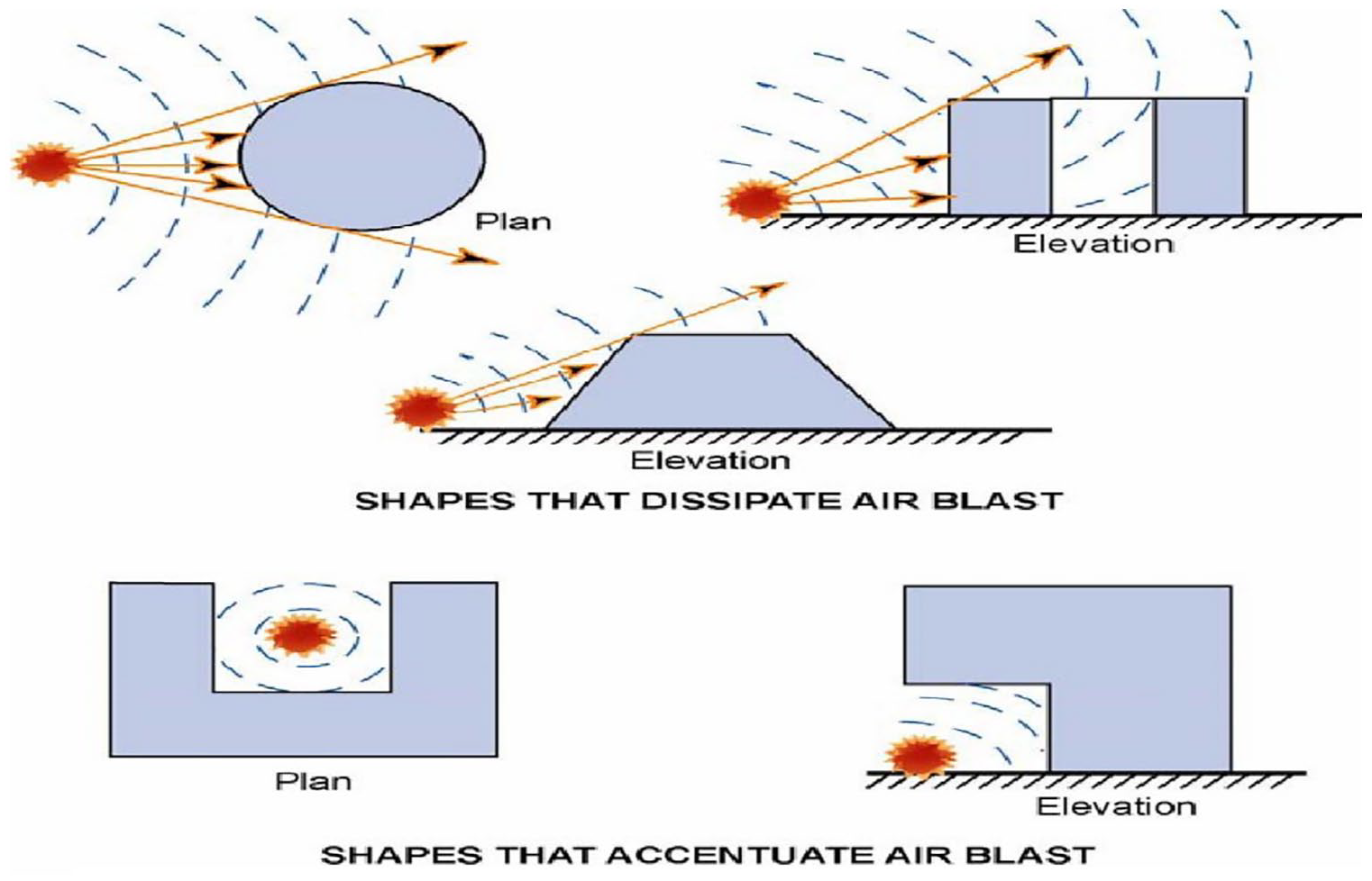
Shapes that dissipate/accentuate air-blast effects (Baker et al., 1983; TM 5-1300, 1990).
The two primary goals for designing a blast-resistant structure are (Goel and Matsagar, 2014; Hao et al., 2016):
To confine the structural damage to an acceptable range that is, to localise the damage.
The ability of a structure to function after the blast that is, survivability of the structure with minimum damage.
Blast design standards such as IS 4991 (1968), IS 6922 (1973), TM 5-855-1 (1986), TM 5-1300 (1990) and UFC 3-340-02 (US Department of Defense, 2008) have given detail the response of building structures to explosions. The response is primarily dependent on several aspects including layout, structural detailing, damping characteristics, material properties, explosive charge and its range, degrees of freedom of the individual components and the entire structure (TM 5-1300, 1990; UFC 3-340-02, 2008). Elimination of the explosive event threat remains the most attractive, competent and cost-effective process in developing designs for facilities on any site. However, based on the threat assessment, it may be unreasonable to assume that the facility will not be exposed to explosive event effects. Maintenance of standoff between the explosive device and the asset remains as one of the most powerful mitigating strategies available to the design team for the development of a structure that affords the best opportunities for risk and consequence management. The general aim of any blast-resistant design is that the robustness and integrity of the structure should be maintained at all times, and removal of key elements will not lead to progressive collapse, as occurred in the case of the Murrah Building in Oklahoma City. A particular attention has been given in TM5-1300 (1990) to the design of chamfered connections between reinforced concrete wall and floor slabs, and beams and columns to reduce stress concentrations at these locations. IS 4991 (1968) classifies the below-ground structures into two categories that is, buried and semi-buried structures depending upon the earth cover and slopes of earth berms (IS 4991, 1968). The buried structure is subjected only to the general overpressure POP, the reflected and dynamic pressures being neglected. The semi-buried structure is subjected to partial dynamic pressures besides the general overpressure. Both are acted upon by air-induced ground shock also (IS 4991, 1968).
In all situations, it is, of course, desirable to investigate the area likely to be exposed to any blast and minimise it (UFC 3-340-02, 2008). It is often worth considering the provision of some form of external protection. For example, it may be desirable to use a burster slab over an underground structure, though it could be that the costs of such a measure may be prohibitive (TM 5-1300, 1990). The use of blast walls adjacent to above-ground structures is another measure to mitigate the explosive-induced threats. It is vital that such walls should be not only robust but that their location relative both to the position of the threat and the buildings that they are protecting is given due consideration (TM 5-1300, 1990; UFC 3-340-02, 2008). Considering the ballistic resistance of a structure, it is vital to arrest missile penetration by providing adequate wall and floor thickness in the chosen material of the construction which might be in the form of steel plates or reinforced concrete slabs (IS 4991, 1968).
It is well established that increased standoff distance is the best mitigation measure against explosive-induced threats. However, in urban environments, it may not always be possible to achieve significant stand-off. In such circumstances, and if the sensitivity of the building to be protected merits it, there may be a case for the construction of a ‘blast wall’ around the building. Blast walls and other similar barriers, when appropriately located, can provide effective reduction of blast wave peak overpressure and impulse. The barrier will achieve this by causing the incident blast wave to be partially reflected back towards the explosive source, and the remainder of the wave being diffracted over the barrier. The schematic layout of the site for protection against vehicle bombs is shown in Figure 12.
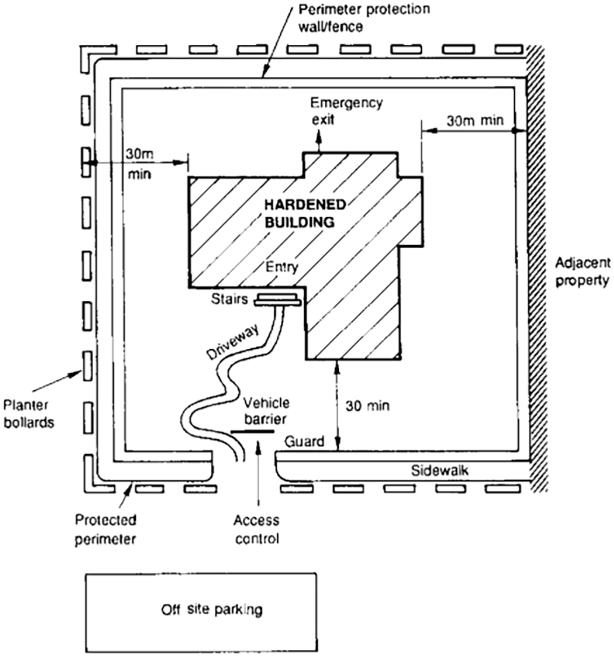
Schematic layout of site for protection against vehicle bombs (Baker et al., 1983; UFC 3-340-02, 2008).
On the ground and buried shallow underground blast-resistant shelters: An abridged review
Organisations of frustrated groups so-called terrorists make even blast structural buildings their targets by displaying such nefarious sabotaging prowess to prove their might (Anas et al., 2021; Goel and Matsagar, 2014). Existing buildings not designed for blast loads may undergo severe damage or even collapse when subjected to such extreme loadings leading to enormous economic losses and human lives (Goel and Matsagar, 2014; Hao et al., 2016). Under such a prevailing socio-political environment, it seems necessary to design safer buildings by incorporating features of blast resistance in the design of the structures.
In the current political scenario, the need for blast-resistant shelter cannot be completely ruled out, however, blast-resistant structures seem to be more important. The shelters were constructed for life protection from blast, thermal and radiation effects in case of accidental explosion or war scenario (Gautam, 2007). However, it can also be used for communication, first aid, command, or control centres during such crises. Their use can further be extended to store explosive materials, fuel, radioactive substances and nuclear ammunition (Gautam, 2007). Figure 13 shows the general requirements for the blast-resistant shelters (Gautam, 2007; Gautam and Pathak, 1997). Following are the benefits of the blast-resistant shelters (IS 4991, 1968; TM 5-1300, 1990).
Thermal protection: (1) A layer of air in the inner and outer liners of the shelter creates a thick, insulating barrier against thermal waves. (2) Recommendations can be made with a site analysis on shelter placement in relation to blast zones and flare stacks.
Craft retention: (1) Aesthetically pleasing and non-confining. (2) Increased productivity for site work. (3) Bright interior.
Versatility: (1) Shelters size from 37 to 3700 m2. (2) Withstands temperatures ranging from −45°C to 60°C. (3) Internal climate control; uniform distribution of heat and/or cooling.
Applications: (1) Lunchrooms. (2) Meeting rooms. (3) Supervisory offices. (4) Shelter-in-place options.
Long life span: (1) Fabric warranted for 10 years’ useful life with proper maintenance.
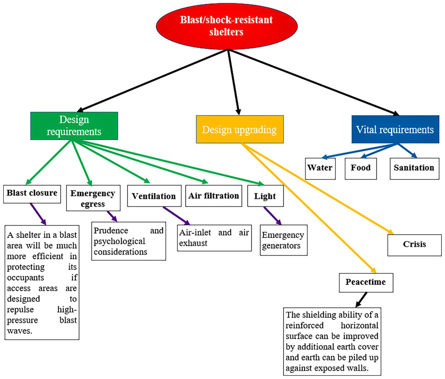
General requirements for blast/shock-resistant shelters (Gautam, 2007; Gautam and Pathak, 1997).
The analysis, design and testing of on-the-ground and buried shallow underground blast-resistant shelters have been investigated extensively by many researchers (Gautam, 2007; Gautam and Pathak, 1997; Holmes et al., 1988; Lal et al., 2000; Liskay et al., 2014; Siddiqui and Ahmad, 2007; Slawson, 1987; Slawson and Davis, 1988; Woodson et al., 1986; Zimmerman and Chester, 1984). The shelters are primarily designed by incorporating features of the materials such as high degree of deformability, high ductility, use of the shock-isolation panels and the mechanism for controlling crack formations (Gautam and Pathak, 1997; Lal et al., 2000).
Zimmerman and Chester (1984)
In this study, the authors developed three underground corrugated metal blast shelters to resist the blast overpressures of 0.45 and 1.55 MPa. The explosive charge consisted of approximately 609 tons of ammonium nitrate fuel oil (ANFO) mixture contained in a 10.67 m (35 ft) diameter spherical fiberglass shell placed at a height of 50.29 m (165 ft) above the ground. The shelters were made of 16 gauge corrugated metal sheets and buried about 0.61 m (2 ft) below ground level (Figure 14). It was observed that the clamped joint of the vertical section of the entryway resisted the blast loading. The blast shelters were found safe against the blast pressure of 0.45 MPa but failed by buckling under the 1.55 MPa peak overpressure. The failure was caused by inadequately compacted backfill and the absence of sufficient soil envelope to provide the necessary strength.
Description of blast shelters tested by Zimmerman and Chester (1984).
Woodson et al. (1986)
Woodson et al. (1986) tested an 18-man, 2.74 m (9 ft) diameter buried steel blast shelter for 0.38 MPa (55 psi) blast pressure generated by 1 Mt nuclear detonation (PETN) using a High Explosive Simulation Technique (HEST). The shelter was constructed from 10-gage corrugated steel and the main section was approximately 8.38 m (27 feet 6 inches) long. Besides, the flume sand was used for the backfill, classified as poorly graded sand (SP) by the Unified Soil Classification System (USCS). The 14.63 × 11 × 0.91 m (48 × 36 × 3 ft) charge cavity was constructed above the blast shelter over which a 1.22 m (4 feet) thick un-compacted sand overburden was placed (Figure 15). It was reported that the minor structural damage and the displacements were <0.01 m (0.5 in). Moreover, the post-test observations revealed that the endplates of the main chamber were un-deformed, and the entryway-shelter connections, closure and entryway incurred negligible damage.
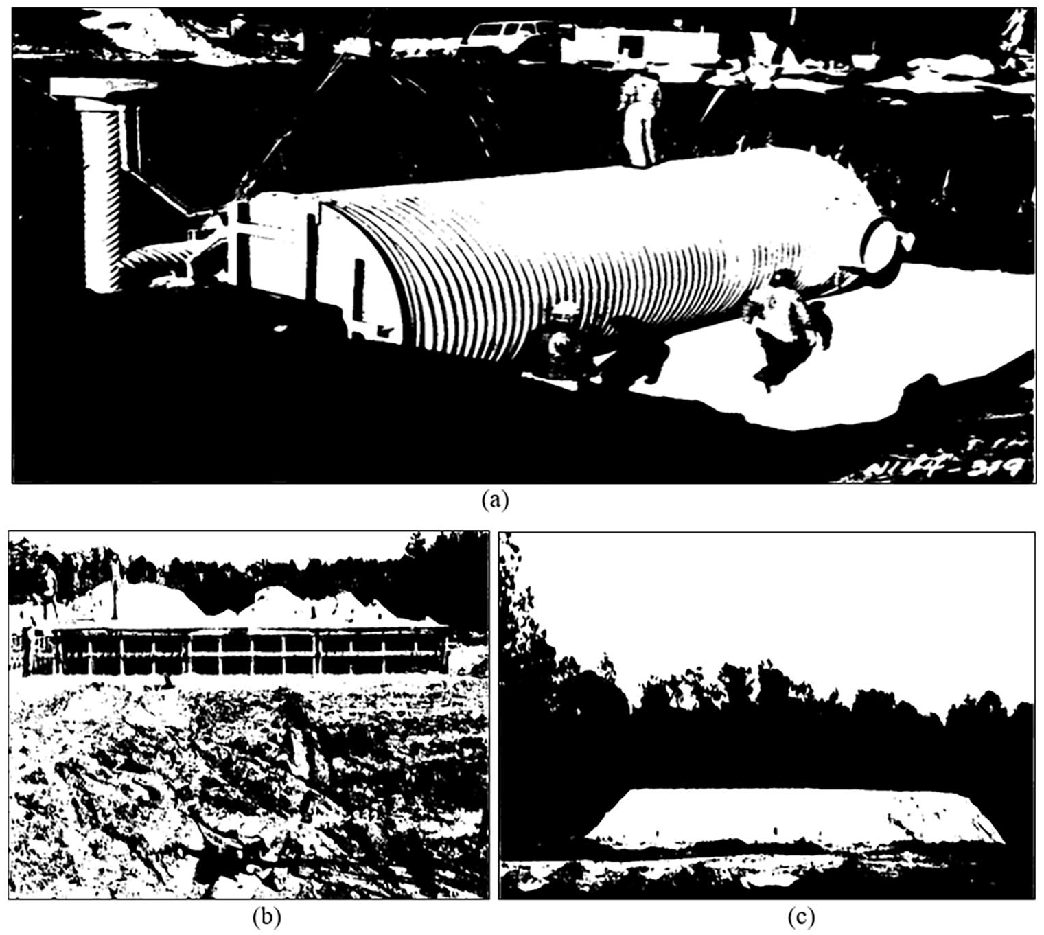
Monochromatic views of blast shelter tested by Woodson et al. (1986): (a) placement of shelter in test bed, (b) charge cavity construction and (c) completed overburden placement.
Slawson (1987)
The author evaluated the vulnerability of the 100 men keyworker RC 3-bay blast shelter designed to resist peak overpressure ranging from 0.90 to 1.10 MPa (130–160-psi) generated from a 1 Mt nuclear surface detonation (PETN) using HEST. A 0.61 m (2 ft) thick concrete sand blanket was used as a backfill around the designed shelter. The 18.28 × 18.28 × 1.22 m (60 × 60 × 4 ft) charge cavity consisted of a wooden framing system that was constructed above the shelter roof over which a 1.22 m (4 ft) thick layer of brown silty sand classified as SP-SM by the USCS was placed. Besides, the compressive strength of concrete at 28 days for the walls and roof was 22.75 MPa with a standard deviation of 3.31 MPa. The yield, rupture and ultimate strength for the roof steel were 0.43, 0.55 and 0.66 MPa, while for the walls these values were 0.52, 0.68 and 0.80 MPa, respectively. The plastic deformations ranging from 0.20 to 0.43 m (8–17 in) at the mid-span of the roof were observed, which the shelter survived. It was found that the considered shelter was safe to resist large deformations without catastrophic failure and the mechanical equipment inside the blast shelter was serviceable under the given blast loadings. Also, the occupant survivability was found possible even at a higher level of blast pressure (1.03 MPa).
Holmes et al. (1988)
Holmes et al. (1988) assessed an 18-man underground steel blast shelter for 1.38 MPa (200 psi) incident blast pressure produced by an 8 Kt surface burst. They used 4685 tons of ANFO charge contained in a 26.82 m (88 ft) diameter hemispherical fiberglass shell placed at a standoff distance of 149.35 m (490 ft) from the target structure. The explosive charge was designed to simulate the response of the components subjected to air-blast pressure and ground shock. The main chamber of the shelter was 8.38 m (27.50 ft) long, 2.74 m (9 ft) in diameter and fabricated from a 10-gage galvanised corrugated steel culvert. The end walls were made of 4.74 mm (0.187 in) thick steel plates following the American Society for Testing and Materials, ASTM A36. Besides, they placed a 0.30 m (1 ft) thick layer of blow sand (backfill) in the testbed prior to the placement of the main chamber, and a 1.22 m (4 ft) thick backfill material over the roof of the blast shelter. The dimensions of the testbed were 15.24 × 7.62 × 4.27 m (50 × 25 × 14 ft). The monochromatic views of the 18-man blast shelter are shown in Figure 16. It was found that the end wall which supported the ventilation system experienced maximum deformation of 15.24 mm (0.60 in), while the end wall which supported the entryway of the shelter suffered maximum deformation of 2.54 mm (0.10 in). Moreover, the fiberglass covers on the entryway hatch faced maximum deflection in the middle of 81.28 mm (3.20 in) (Figure 16(d)). The emergency exit cover plate and entryway frame incurred maximum damage and failed during the test (Figure 16(e)). Figure 17 shows the predicted shock wave spectra for different critical damping values (0%, 5% and 10%) and predicted blast pressures inside the shelter for two different targets. In the case of target-1, the explosive charge was placed on the floor at the centre of the blast shelter, while in the case of target-2, the charge was located in the middle of the end wall close to the entryway. The floor acceleration inside the bottom surface of the shelter was found <10g’s at a resonant frequency of 10 Hz (Figure 17(a)). It was concluded that the 18-man keyworker blast shelter was safe against the design pressure of 1.02 MPa (148 psi) but failed to resist 1.38 MPa (200 psi) peak overpressure.
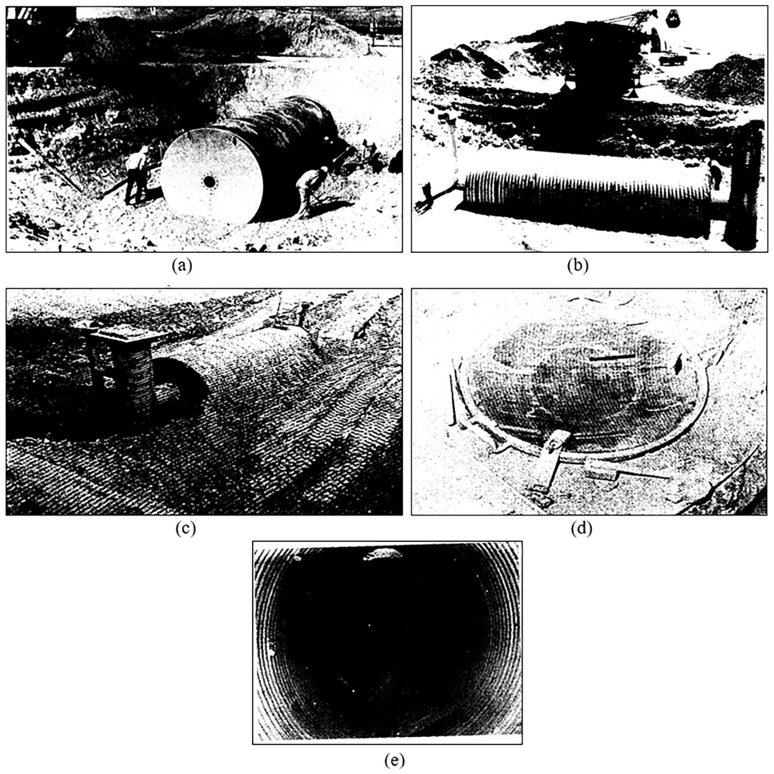
Monochromatic views of 18-man blast shelter tested by Holmes et al. (1988): (a) the blast shelter without entryway and ventilation system attached, (b) the blast shelter with entryway and air-exhaust stack attached, (c) posttest view of the shelter, (d) close-up view of the entryway hatch and (e) posttest view of the emergency exit failure.
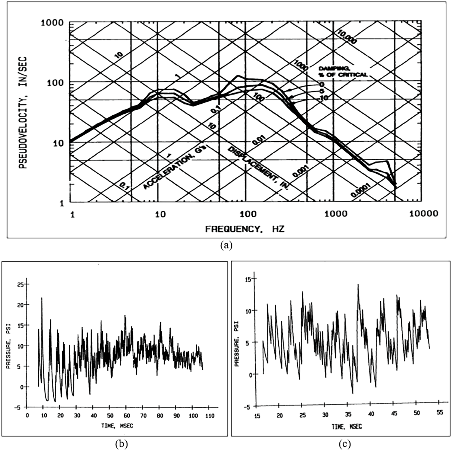
Predicted responses (Holmes et al., 1988): (a) shock spectra, (b) pressure profile for explosive location Target-1 and (c) pressure profile for explosive location Target-2.
Gautam and Pathak (1997)
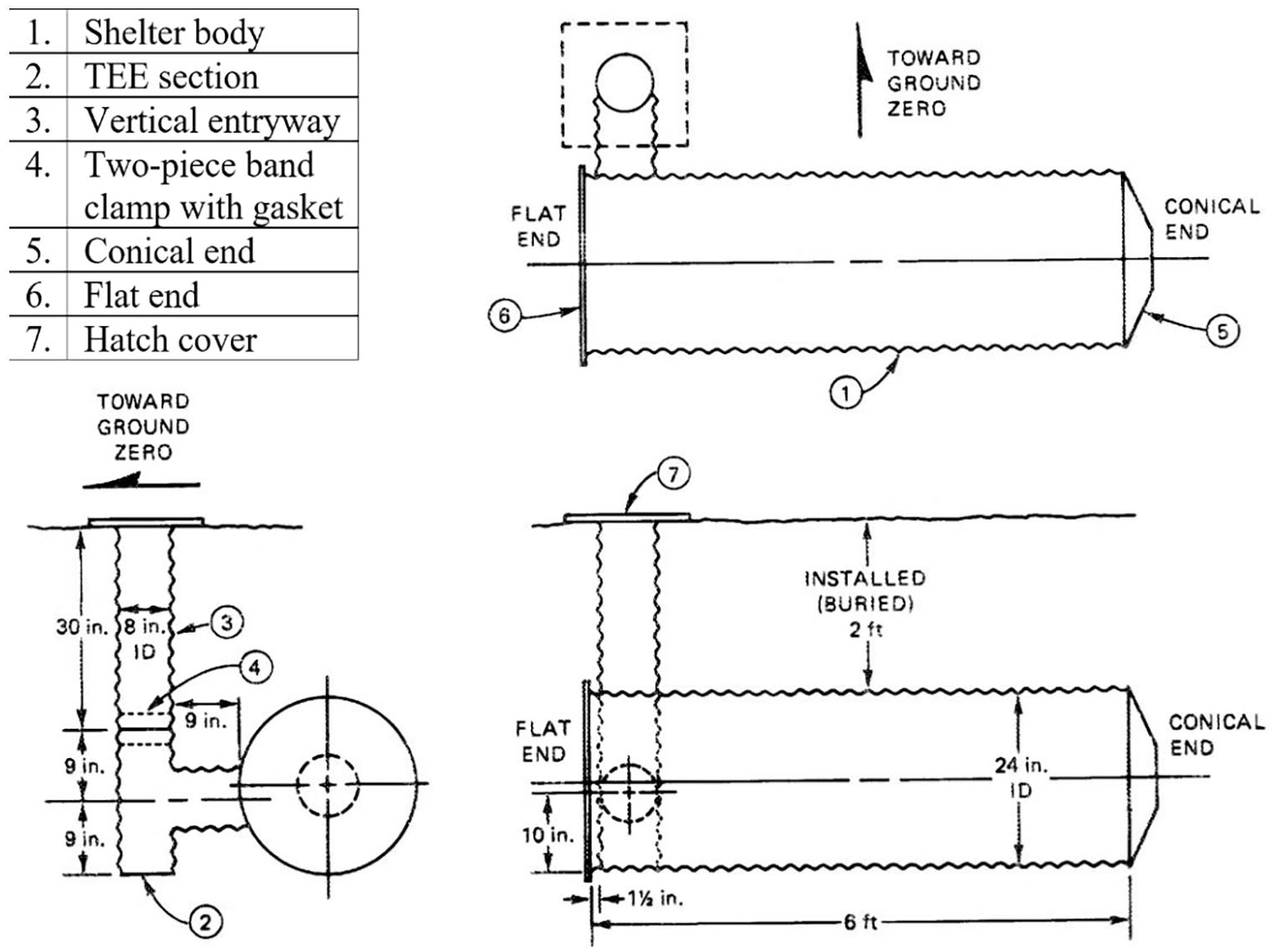
In this research, the authors developed an underground circular cylindrical blast shelter to resist design blast pressure of 0.08 MPa (12 psi) generated from a cylindrical charge (TNT) of 10 kg placed at 3.50 and 5.00 m standoff distances in free air, and radiation effects of 20 Kt atomic ground detonation. The shelter was made of 3 mm thick corrugated steel sheets. They designed a cylindrical module of 2.50 m diameter and 6 m length connected with a corner entrance module on one side for entry/exit which was buried under an earth cover of 1.50 m. The detailed dimensions of the modules and one steel sheet segment are shown in Figure 18. Besides, rubber gaskets, polyethylene sheets and flash strips were used to make the cylindrical and corner entrance modules leak-proof. The maximum strains of 291.8 and 250µ in circumferential and meridional directions were recorded. Results indicated that the cylindrical and corner entrance modules experienced maximum deformations of 118 and 70.10 mm.
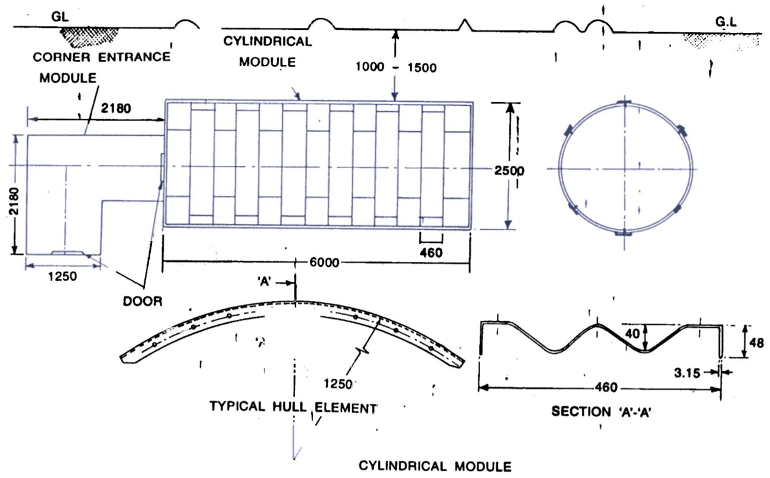
Description of blast shelters tested by Gautam and Pathak (1997) (dimensions in ‘mm’).
Samara (1998)
Samara (1998) discussed the importance of architectural, electrical, plumbing and mechanical requirements for the blast-resistant control centres. Architectural requirements such as use of ductile materials, 6 mm thick safety glass as described in ANSI Z97.1-2015 (American National Standard ANSI Z97.1, 2015), porthole or bull’s-eye windows, deflecting shield walls, shock-resistant doors, raising the finished floor level by 600–900 mm, minimising the number of openings and exterior doors and single-storey construction should be recommended while designing the buildings for blast resistance. Besides, a positive pressure ventilation system within the building must be provided following the Standard for Purged and Pressurised Enclosures for Electrical Equipment, NFPA 496-2017 (NFPA 496, 2017), with an external air intake source located at least 25 ft above the ground level.
Lal et al. (2000)
The authors designed and tested four on-ground reinforced cement concrete (RCC) double roof blast protective structures with 200 mm diameter Hume pipes as an energy-absorbing layer (EAL) in-between to resist shock loads generated by high explosive (HE) cylindrical charges detonated at varying standoff distances (between 0.50 and 2.5 m). The description, pre and post-test views of the tested blast protective structure are shown in Figure 19. The stone boulders of size 225–380 mm were placed over the top of the considered structure. Four blast tests with different explosive charges and standoff distances simulating four different scenarios namely, free air burst, contact detonation with boulder stack, buried detonation and contact detonation with the upper RCC roof, were performed. They have noticed that when 10 kg HE charge was detonated at a standoff distance of 1 m from the boulder stack surface, the upper roof experienced a pressure of 0.25 MPa (2.50 kg/cm2) and the lower roof suffered a maximum displacement of 4.70 mm and increased to 28 mm in the centre when 30 kg HE cylindrical charge was detonated in contact with the boulder stack, while in case of 30 kg TNT HE charge when buried and was detonated in the boulder stack at a depth of 1 m, the displacement in the lower roof was now increased to 56 mm and the cracks were developed at the junction of RCC roofs and RCC walls (Figure 19(c)). The wide cracks appeared at the junction of the RCC roof and RCC walls when a 30 kg HE explosive charge was detonated in contact with the upper or top roof of the blast protective structure. Also, a small lump of 0.15 m (6-inch) diameter was spalled from the lower roof of the structure. It was found that shock dissipation through boulder media reduces the shock intensity to its one-tenth level in the case of medium-range of shock pressure (<98 MPa), while for the case of intense shock (>98 MPa), the reduction in shock intensity was approximately up to fifteen times. The shock isolation system or the energy-absorbing layers reduced the strains in the lower roof by almost 50%.
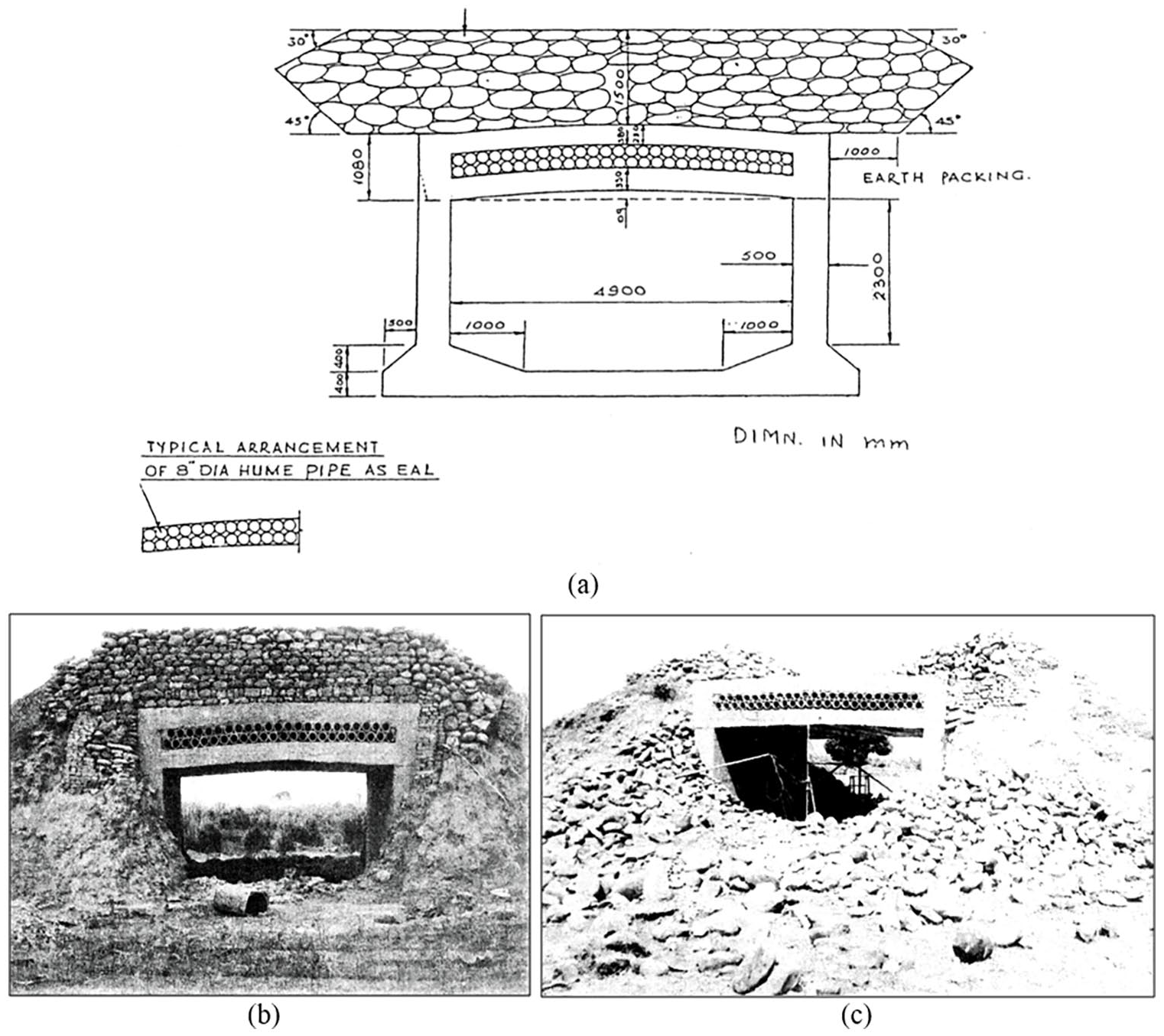
Shock-resistant double roof RCC structure (Lal et al., 2000): (a) description of the structure (dimensions in ‘mm’), (b) pre-test view and (c) post-test view.
Goel and Matsagar (2014)
In this study, various empirical, semi-empirical and numerical (or first principle) methods to predict the effects of blast on structures were reviewed and discussed the importance of designing a blast-resistant wall, named as sacrificial blast wall, using various-energy absorbing materials such as polymeric foams, metal foams, etc. The empirical methods are developed based on extensive investigation of large sets of published experimental data collected over a long period and thus restricted by the extent of the database and its reliability over the techniques employed at that time, while the semi-empirical methods are correlated with the physical phenomena and rely on published case studies or extensive data. The common example of an empirical (or analytical) approach-based guideline includes CONWEP 2.00 (1991), IS 4991 (1968), IS 6922 (1973), TM 5-855-1 (1986), TM 5-1300 (1990) and UFC 3-340-02 (US Department of Defense, 2008) (UFC 3-340-02, 2008). Numerical methods are driven by mathematical formulation, which relies on the dynamics of the problem. The finite element method (FEM), boundary element method (BEM) and finite difference method (FDM) approaches fall under this category. Besides, the main function of the sacrificial wall was to retain the energy imparted by the detonation from reaching the protective structure (Figure 20). The provision of such blast wall may serve as a sacrificial compound wall around the buildings against a higher yield of explosive detonation and protect the building from such blast.
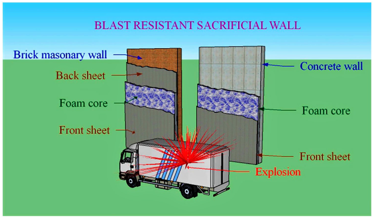
Typical layout of sacrificial blast wall proposed by Goel and Matsagar (2014).
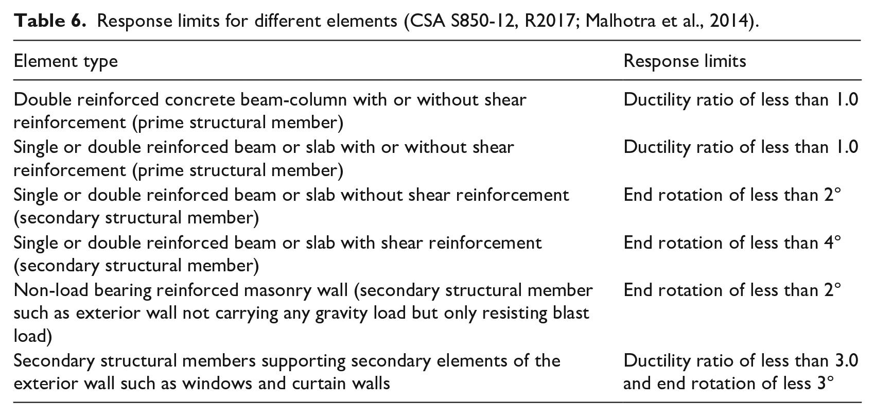
Malhotra et al. (2014)
Malhotra and his co-authors discussed the response limits for different building components subjected to blast loads defined in the Canadian Standards Association Standard, Design and Assessment of Buildings subjected to Blast loads (CSA S850-12, R2017). Referring to CSA S850-12 (R2017), the response limits for building components such as masonry wall, beam, column and slab are given as end rotations or ductility ratio (Table 6). Shear force corresponding to the response limits should be considered in the design of components subjected to blast-induced loadings and the structural designers must ensure that shear failure does not take place.
Response limits for different elements (CSA S850-12, R2017; Malhotra et al., 2014).
Conclusions
In this review paper, it has been attempted to make understand the phenomenon of the blast, blast wave parameters and various empirical blast models available in the open literature. Also discussed the designing and testing of on-the-ground and buried shallow blast/shock-resistant shelters; damage criteria for residential buildings based on displacement, energy ratio, ground velocity and acceleration; and peak particle velocity (PPV) and acceleration (PPA) prediction models. Reviewing major research publications on blast loading, it appears that this field of research has not emerged out of its nascent state. As such, prior to further growth, it is important to cross-correlate the outcomes of the available studies.
Based on the review of the reported publications, following are the major findings:
Occurrence of extreme loadings on the structure caused by man-made or accidental explosions is not uncommon. Recent ammonium nitrate explosion at Beirut seaport (Lebanon) and devastation resulted out of it is an eye-opener. The explosive-induced threat is changing from the large-yield weapons fired against urban areas to intermediate-range weapons targeted with greatly improved accuracy on more specific industrial concentrations and military targets (Duvall and Fogelson, 1962). This requires consideration of an adequate level of blast-resistant factors in the analysis and design of the structures or structural elements.
Safety of the structures out of increasing accidental explosions and intentional blasts is of serious concern. When a quantity of high explosive material is detonated in the air, the hot, highly compressed gaseous products of the reaction rapidly force the surrounding air out of the volume it occupied and cause to generate blast wave. Moreover, it is becoming increasingly important to ensure that critical components are blast-resistant to prevent the triggering of disproportionate or progressive collapse of the structure. One of the essential concept to prevent building damage through a progressive collapse is the ductile design and allowing redundancy to the structural system just like in the earthquake-resistant design of structures (Goel and Matsagar, 2014).
For realistic combinations of explosive yield and building dimensions, the rarefaction waves from the edge of an object, traveling at the local speed of sound, will reach regions on the surface of the target object before the positive phase is complete. When this occurs, the pressure load rapidly decreases from the incident pressure to the stagnation pressure. This phenomenon cannot be represented by a simple Friedlander form (Dewey, 2018). Idealised overpressure waveforms (i.e. Friedlander form) are generally used for the loads with no consideration of edge effects from finite targets.
Elements with mass and ductility that stand between an explosion site and a target area can act to dissipate energy as they fail from the effects of the blast. In fact, designers sometimes do rely on specific sacrificial elements to reduce the blast effects on critical structural elements. The bases for this consideration are twofold: (1) through its failure, the sacrificial element dissipates energy that would otherwise be imparted to the structural element, and (2) for the brief time that the sacrificial element stays in place, it acts to reflect the shock front, thereby reducing the impulse felt by the protected structural element.
Various empirical blast models have been given by the researchers. However, it remains unclear that which empirical model is to be considered as the most superior/accurate one.
Artificial Neural Network (ANN) technique is found in close agreement with the experimental results and therefore may also be used to predict the peak particle velocity (PPV) generated from blast-induced ground motions (Khandelwal and Singh, 2007).
It is worth noting that the degree of damage to a structure subjected to the underground blasting is most closely related to the magnitude of the ground particle velocity of the wave motion passing through the supporting geological media (Duvall and Fogelson, 1962). On an average, the damage levels can be grouped into two main categories: (1) PPV of 0.14 m/s (5.40 in/s) corresponds to minor damage; (2) 0.19 m/s (7.60 in/s) corresponds to major damage. Besides, ground motions that have PPV above 0.05 m/s (2 in/s) have a fair probability of causing some damage to the structure or structural elements, while ground motions that have PPV <0.05 m/s have a low probability of producing any damage.
The blast/shock-resistant shelters are primarily designed by incorporating features of the materials like high degree of deformability, high ductility, use of the shock-isolation panels and the mechanism for controlling crack formations (Gautam and Pathak, 1997; Lal et al., 2000).
Circular cylindrical-shaped shelters made of corrugated steel sheets are mostly adopted for the construction of the underground or buried blast shelters, while for the construction of the on-the-ground blast shelter, a double RCC-roof structure with a shock isolation system is considered. In the case of underground blast shelters, the overburden placement comprises mostly un-compacted sand, which reduces the intensity of the shock impinging the shelter roof, while the overburdened stone boulder plays a significant role in the shock dissipation for the on-ground blast protective structure.
The effects of the ground shock on personnel inside the blast shelter depend on the floor material, position of the individual and the amplitude, duration, frequency and direction of the ground shock. Holmes et al. (1988) recommends a maximum design spectral acceleration of 10g’s at frequencies at or below the resonance frequency of a man in the standing position (i.e. 10 Hz). The use of the plywood floor inside the shelter reduced the effective shock amplitudes received by the occupants. Impact injuries occur at much lower spectral accelerations (between 0.50g and 1.00g) for an unrestrained man in the seated or standing position. These injuries were the result of falling and hitting the floor or other objects. Impact injuries may be reduced by the use of padded surfaces and/or restraints to prevent movement.
Mechanical, architectural, plumbing and electrical requirements must be incorporated into the design to ensure that a blast/shock-resistant building behaves like a blast/shock-resistant system (Samara, 1998). Besides, a positive pressure ventilation system within the building should be provided with an external air-intake source located at least 7.62 m (25 ft) above the ground (Samara, 1998).
Padded surfaces are used to ensure the survivability of the equipment (communication devices and generators) and occupants inside the blast shelter (Holmes et al., 1988; Zimmerman and Chester, 1984).
Given that buildings of modern construction are inherently robust, the key to improved building performance against blast is seated in the need to keep the blast from entering the building. This can be achieved by means of a strong building facade, based on the use of laminated glazing assemblies. Performance can further be enhanced by the creation of large stand-off between the source of the blast and the building. However, in populated cities, a large standoff distance is not possible. At such places, provision of blast walls or sacrificial elements or line-of-sight barriers provides a better option to reduce explosive-induced threats.
Critical structural components such as columns of the ground storey are more vulnerable to accidental and intentional explosions and therefore require to be provided not only strength but adequate ductility and continuity of the lateral reinforcement to control damage and prevent the possibility of the progressive collapse.
Numerical simulation is an alternative methodology for the blast resistance analysis of the structures. However, accurately simulating the response of a structure requires a high-fidelity numerical/analytical model (Hao et al., 2016).
Future recommendations
Based on a closer review of the reported publications, the authors feel that the following aspects should/could be considered for subsequent research:
Weather that is, temperature, humidity and wind, at the test site may influence the blast pressure-time history and therefore the blast performance of the target structure. Weather parameters should be reported with experimental studies and incorporated in the numerical/analytical investigations.
Variation of stresses in the materials should be described.
Correlation of the stresses with damage should be focused upon.
The maximum quantity of the charge that would not affect the structure or structural element may be investigated by conducting more tests or numerical simulations.
Significant damage parameters with regards to crack such as length, width and depth; and damage dissipation energy should be accounted for in investigations, experimental and numerical both.
Occurrence of extreme loadings on the structure caused by man-made or accidental explosions is not uncommon. Such loadings jeopardise the safety/stability of the structure if the key load-carrying member(s) are damaged. Strengthening of compression members of the buildings which are more vulnerable to blast loading may be required, and therefore, is of considerable interest to the structural designers.
The event of the equal arrival time of the air-blast and ground shock could give rise to amplified blast pressures and be the worst condition for investigation of structures or structural elements subjected to the blasts, hence should be taken care of in future research.
Comparison of existing empirical equations for blast wave parameters is worth conducting.
Additional research needs to be conducted for response spectrum solutions and fragility curves for structures subjected to blast-induced impulsive loading.
Energy absorbing materials such as fiber composites, polymeric foams, metal foams, coal-based carbon foams, magneto-rheological (MR) fluids, metal plates, etc. should be adopted as blast shock absorbing agents.
Combined effect of air-blast and fire on structures may be investigated in the subsequent research.
Strengthening of the damaged structure or components under blast loading is worth studying.
Evaluation of the overturning stability of the structures subjected to simultaneous ground shock and air-blast pressure should be performed in the subsequent investigations.
To provide effective automatic closure for blast shelters threatened especially by small nuclear weapons, the Over Lapping-Flaps Blast Valve should be further developed and tested.
Quickly closable blast doors to protect all openings will be essential components of blast-resistant shelters built-in rear areas and not threatened by a ground assault.
Possible application of the carbon steel hollow pipes which are having better resistance to corrosion and impact energy absorption capacity between the two RCC roofs the double roof RCC blast protective shelter designed by Lal et al. (2000) seems to be a better option for enhancement of the blast performance of the shelter.
Design provisions for the strengthening of structural components against blast-induced threats need development.
Cost analysis for enhancing the blast performance of the shelters/structures should be conducted.
Master plans and building bye-laws need to be revised.
Footnotes
Declaration of conflicting interests
The author(s) declared no potential conflicts of interest with respect to the research, authorship, and/or publication of this article.
Funding
The author(s) received no financial support for the research, authorship, and/or publication of this article.