
Abstract
This study aims to investigate the effects of the draw beads on the crashworthiness of the aluminum tubes under axial quasi-static loading. Based on this design philosophy, a total of 12 beading tube designs with various configurations were developed. Within each design, the effect of arrangement bead form on the crashworthiness performance was also analyzed. A finite element model, validated using experimental tests, was used to study the crashworthiness performance and progressive deformation of the tubes. Based on the results, a multi-criteria decision-making method known as Technique of Order Preference by Similarity to Ideal Solution was employed to determine the most suitable tube that features high energy absorption and low impact force. The best tube with a high score was selected to investigate the effect of bead formed direction on aluminum tubes. Consequently, the study identified a bead shape tubes configuration that exhibits superior crashworthiness and low impact force. The beading tube design methodology presented in this study allows the exploitation of variable shapes geometries for the development of high-efficiency energy-absorbing structures and their crushing behaviors.
Introduction
Thin-walled structures have attracted a considerable amount of attention in many engineering fields for the design of the energy absorbers due to their lightweight, low manufacture cost and high energy absorption efficiency (Ha & Lu, 2019, 2020; Lu and Yu, 2003; Ha et al., 2018, 2019, 2021a, 2021b). Consequently, a series of numerical, theoretical and experimental investigations have been carried out to evaluate the energy absorption characteristics of the thin-walled structures (Lu and Yu, 2003; Wierzbicki and Abramowicz, 1983; Guillow et al., 2001; Abramowicz and Jones, 1997; Abramowicz and Jones, 1984; Kim, 2002). Thin-walled structures can be produced by sheet metal forming methods such as deep-drawing, extrusion and hydroforming methods. Plastic deformation occurs during forming of the thin-walled tube which produces work hardening. During the forming process, residual stresses, work hardening, thickness variations, and plastic strain occur. Studies have shown that the forming history had a significant effect on the energy absorption performance of the thin-walled structures (Karagöz and Yıldız, 2017; Oliveira et al., 2006; Huh et al., 2003). (Dutton et al., 1999) examined the effect of forming parameters from the forming analysis of the siderail on its crashworthiness. They formed a siderail structure by hydroforming and mapped the forming results to the impact analysis. They found that forming history affected the crashworthiness and it was important to consider the forming history to obtain real crashworthy behaviors. (Gümrük and Karadeniz, 2009) numerically investigated the effects of the deep-drawing process on the crashworthiness of top-hat thin-walled structures. They reported that the residual forming data and the effects of spring-back significantly influenced the crashworthiness of the structures and they should be considered in the numerical analysis. (Lee et al., 2005) numerically investigated the influence of back stresses during forming processes of siderail structures on their crashworthiness. The siderail structures were manufactured by deep-drawing while the tube was formed by hydroforming processes. They indicated that the back stresses during the forming process should be considered in the forming and impact simulation to obtain a more reliable and accurate result. (Krusper, 2003) examined the influences of the forming history on the crash performance of a simple hat profile structure. They found that plastic strain and thickness distribution had an important role in the crash response. (Williams et al., 2005) numerically and experimentally investigated the influence of the hydroforming process on the crashworthiness of aluminum alloys. They concluded that the energy absorption capability of the hydroformed tubes decreased with the decrease of the corner-fill radius. In another study, (Kim et al, 2003) numerically examined the forming effects including work hardening, non-uniform thickness distribution on the crashworthiness of the vehicle structures. They found that forming effects significantly influenced the deceleration pulse and deformation mode. An investigation was performed by (Yamashita and Bin Khalil, 2015) on the energy-absorbing performance and deformation behavior of the press-formed aluminum alloy shells. They found that axisymmetric plastic buckling deformation for an in-plane axisymmetric compressive stress field was effective for increasing buckling resistance (Tsukamoto, 2015) studied the dynamic compressive behavior of the deep-drawn cups consisting of aluminum/duralumin multi-layered graded structures and revealed that the deep-drawn cups consisting of six-layered clad structures had superior impact characteristics such as high energy absorption, high maximum force and low maximum displacement. Another researcher studied the mechanical behavior and energy absorption characteristics of single- and bi-layer cups under axial quasi-static compressive loading (Ghasemabadian et al., 2019). Based on the experimental results, they showed that the layer order of the bi-layer cup significantly influenced the energy absorption capacities of the cup, especially, the absorbed energy and mean crush force of the structures with stainless steel as the outer layer increased 8% and 14%, respectively.
The aforementioned studies indicate that the possible design solution is the application of a trigger (bead, notch or dent) to create the desired crashworthiness structures. There are numerous publications concerning the problem of energy absorption of thin-walled tubes with corner dents (Chen et al., 2018; Ferdynus et al., 2019), triggers (Marzbanrad et al., 2009; Qureshi and Bertocchi, 2013; Yang et al., 2017; Darvizeh et al., 2017), windowed (Nikkhah et al., 2017, 2019; Song et al., 2013), however, only a few of them are devoted to tubular structures with bead draws formed (Wang et al., 2020). Bead draw as a trigger mechanism promotes a progressive buckling mechanism of thin-walled structures.
In this study, the bead-shaped trigger mechanism was introduced to the tube to reduce the peak crushing force and to obtain a more stable deformation mode. Experimental and numerical validation and crashworthiness analysis of the bead draw tubes were carried out under axial loading. The numerical simulation was performed with LS-DYNA in order to evaluate crushing behavior and crashworthiness of the tubes. It is noted from the results that the energy absorber of bead draw tubes needs to consider the forming effects for an accurate evaluation of the crashworthiness of a tube that strengthens and decreases collision impact force.
Materials and methods
Geometry and material of draw bead tubes
All the bead draw square tubes with the same area of 10,000 mm2, length of 200 mm and wall thickness of 2 mm were considered in this study. The geometry of the tubes is shown in Figure 1. The draw bead formed in the horizontal and vertical direction with different arrangements on each side of the tubes. All the draw beads were formed with equal distance from each other and located below the top end or upper the bottom end with a distance of 40 mm. The depth of the mentioned draw beads was set as 3 mm. In the bead-drawing process, stresses, thickness variations, and plastic strain were occurred in the aluminum tube. The thinning phenomenon was concentrated in the region where the bead shape was located. The wall thickness value was initially 2 mm; however, the thickness of the bead drawing ranged from 1.90 mm to 1.95 mm after forming process. The thickness difference did not affect the results due to the decrease in the size of sheet metal elements after deep-drawing formed. Total 12 draw bead tubes named B1 to B12 and a simple square tube (S) are shown in Figure 1.
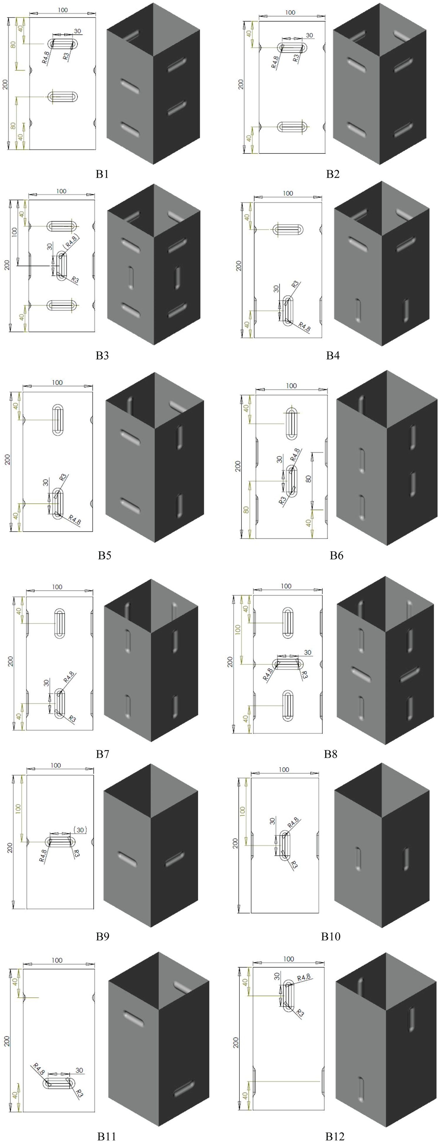
Bead draw square cross-section tubes configurations.
Experimental tests
The tubes were formed by draw beading molds under manual press. The tubes were placed horizontally between lower and upper mold parts and beading the tubes, as shown in Figure 2. The lower mold was fixed and bolted to guide plates while the upper mold was then pressed on the tubes to form the draw beaded tubes. Finally, the formed tube configurations after the forming process are shown in Figure 2(c).
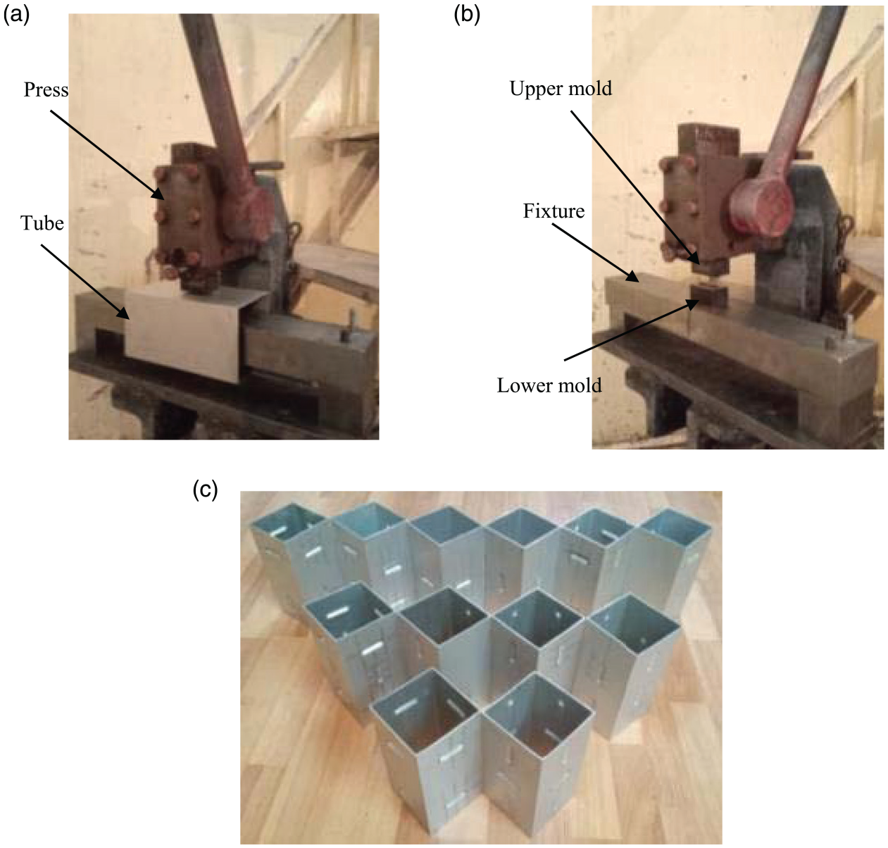
Experimental molds instruments: (a) press, (b) molds, (c) draw bead tubes.
The draw bead tubes were extruded of Aluminium alloy AA6060-T4, with density being 2700 kg/m3, Young’s modulus being 68 GPa, Poisson’s ratio being 0.31 and yield stress of 69 MPa. A tensile test has been performed using a universal test machine (STM-150) to obtain the true stress-strain curve of the material (Figure 3).
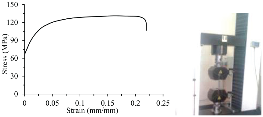
True stress-strain curve of AL6060-T4.
Finite element modeling
Finite Element (FE) model of draw bead tubes was simulated using an LS-DYNA solver to analyze the progressive compressive behavior and energy absorption. All the designs were modeled using Belytschko-Lin-Tsay four-node shell elements with 10 integration points through the thickness. An element size of 2 × 2 mm was found to be adequate for the solution based on the mesh convergence analyses study. The boundary conditions were applied as shown in Figure 4.
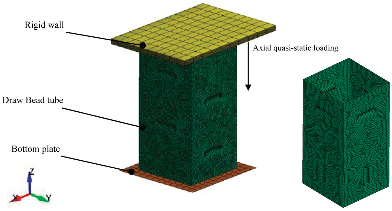
Boundary conditions and mesh resolution of the finite element model.
The draw bead tubes were positioned axially between two rigid plates. The bottom plate was fully fixed. Meanwhile, the top rigid plate was modeled as a mass of 150 kN that moved vertically onto the tubes. The mass value selection ensured that all draw bead tubes could be fully crushed at an impact velocity of 10 mm/min. In order to avoid penetration problems between the tube surface to the rigid walls, the surface-to-surface contact algorithm was used for the FE model. In addition, the single-surface contact was employed to prevent interpenetration between the draw bead tube walls during the crushing process. The Coulomb friction coefficient at all contact surfaces was considered 0.15 (Nikkhah et al., 2017).
Crashworthiness parameters
To study the crashworthiness of the draw beads tubes, three parameters are considered: Specific Energy Absorption (SEA), Peak Crushing Force (PCF) and the Crush Force Efficiency (CFE). The specific energy absorption (SEA) is the energy absorption (EA) divided by the mass (m) of the tube and it can be calculated as shown in equation (1) (Ha and Lu, 2020; Yuen and Nurick, 2008)
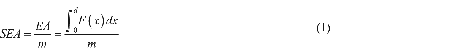
where F(x) and d are the load and the deformation distance, respectively. The greater SEA, the better the energy absorption behavior of the structures. Peak Crush Force (PCF) is defined as the highest force observed after the elastic region in the force-displacement response. Generally, a lower PCF is preferred to prevent instant deceleration which is undesirable for crashworthiness. So conversely to SEA, the lower the PCF, the better the energy absorption of the structures.
Consequently, CFE can be expressed using equation (2)

where MCF is the mean crushing force. For the crashworthiness design, the higher the CFE, the better the consistency in energy absorption throughout the collapse.
TOPSIS multi-criteria decision-making method
Technique of Order Preference by Similarity to Ideal Solution (TOPSIS), which is a multi-criteria decision-making method, was used to determine the best draw bead configuration in this paper. This method was developed by Hwang and Yoon (Yamashita and Bin Khalil, 2015) and it was fully explained in the authors’ previous work (Tsukamoto, 2015). Technique of Order Preference by Similarity to Ideal Solution considered 12 alternatives representing the number of the tubes in this study and 36 design criteria representing the crashworthiness metrics of the tubes including 12×SEA, 12×PCF, and 12×CFE. Two artificial ideal alternatives were assumed within the framework of TOPSIS. The positive ideal alternative is the design, which has the best level for all indices. Meanwhile, the negative ideal alternative is the design, which has the worst indices. Technique of Order Preference by Similarity to Ideal Solution seeks for the alternative that is closest to the positive ideal solution and farthest from the negative ideal alternative. The highest score tube is selected as a high crashworthiness performance. Implementation of the TOPSIS method is as follow:
There is a design matrix (X), that include two parts, n criteria and m candidate. This matrix maps the candidates to selection criteria in order to find the best case. The candidates are the different draw bead tubes and the selection criteria are crashworthiness parameters like PCF and SEA. The row and column of the matrix X ij are the value of candidate i with respect to criterion j. In order to have a normalized design matrix following equation is used
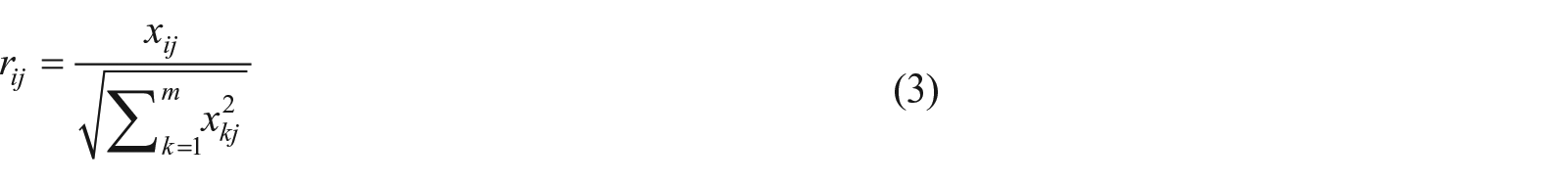
where, r ij is the element of normalized design matrix R.
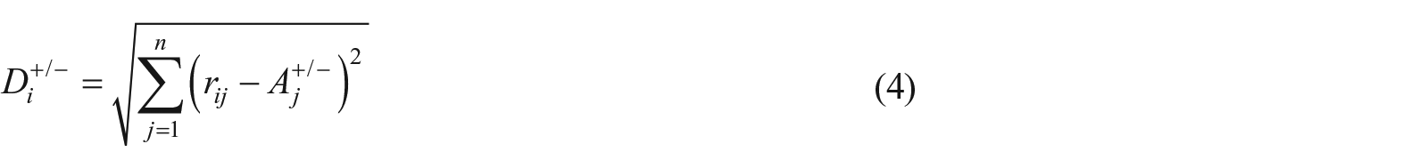
Then, each criterion has its own weight factor. In this study, these factors have the same weight thus the results of this step play a neutral role on the final score of the tubes. Finally, from the matrix R, both positive ideal and negative ideal candidates can be determined. (A+) is the positive ideal candidate which has the lowest PCF and highest SEA while the negative ideal candidate (A−) has the highest PCF and lowest SEA among all candidates. The distance of the ith candidate to the ideal positive and negative candidates, denoted by D i + or D i −, is given by equation (4)
The relative closeness of each candidate to the ideal candidates is calculated by the following equation (5)

In which S i + is the relative closeness of the ith candidate. The candidate with S+ closer to 1 is the best candidate.
Results and discussion
Validation of the numerical model
Validation of the FE model under axial crushing test on the simple tube and B2 tube has been conducted. The aluminum square tubes were cut out of a 6 m long commercial tube manufactured by an extrusion machine. The width, length and thickness of the square aluminum tube were 100 mm, 200 mm and 2 mm, respectively (showed in Figure 4). The test was performed on a universal test machine (capacity up to 150 kN). The bottom of the tube was put freely on the base plate and a top plate moved down to crush the tube along the axial direction. The loading process was under the quasi-static condition with a crushing speed of 10 mm/min.
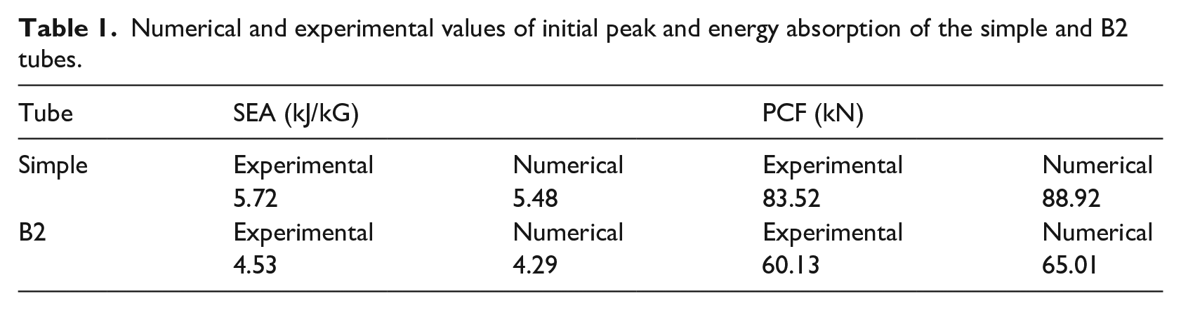
Figure 5 shows the failure modes of the square tube and the draw bead tube B2. It is can be seen that both tubes collapsed in symmetric mode. A good agreement is also found between the deformed shapes predicted by simulation and those of experiments, as shown in Table 1. The FE model has shown good accuracy in predicting the load-displacement relationship under axial crushing load, which ensures the trustworthiness of the crushing response obtained from simulation for different bead draw tubes.
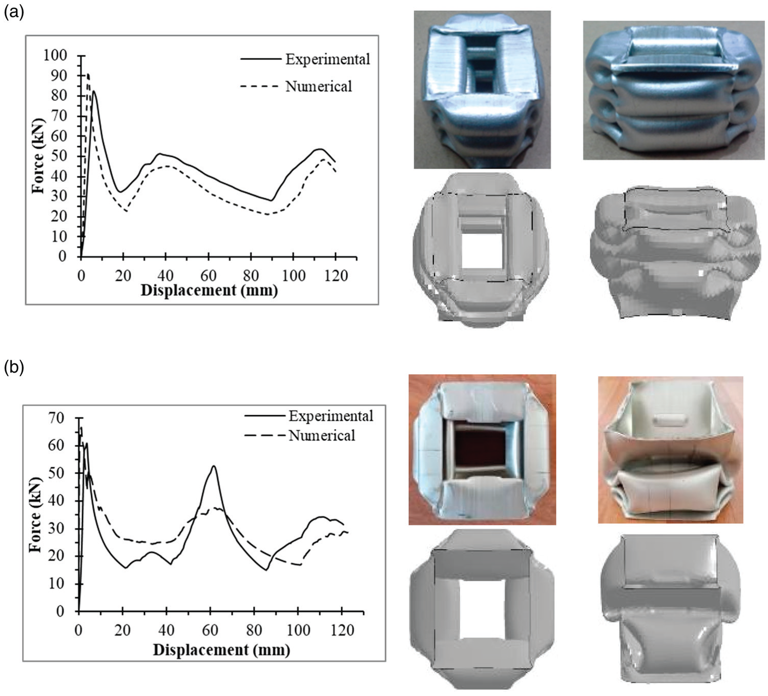
Force-displacement curve, deformation modes and SEA of the experimented tubes: a) Simple, b) B2.
Numerical and experimental values of initial peak and energy absorption of the simple and B2 tubes.
Crashworthiness analysis of draw bead thin-walled tubes
In the present study, the square section tubes with 12 different arrangements of the draw bead on the surfaces of tubes and the square tube without the draw bead, “S” were investigated. Due to the thinning in the location of the bead draw trigger mechanism during the deep-drawing process, the first folding of the draw bead tube was occurred easier and the first reaction force was lower compared to the square tube without the draw bead, “S”. The draw bead helped to reduce the peak crushing force and they contributed as the trigger mechanisms (Figure 6(a)). For all the tubes, a steep rise in the gradient of the force was observed until the onset of deformation. Following this, the load supported by the designs suddenly decreased as the draw bead tubes started deforming. The draw bead tubes reached the PCF earlier than the simple tube. This means that the draw bead tubes B1-B12 tubes damped the crushing force quickly. The PCF of the draw bead tube occurred at the crushing strain of 1.25% while the PCF of the normal square tube occurred at the crushing strain of 3%. It is also seen that the PCF of the tubes with vertical beads namely B6-B7-B10-B12 was higher than that of the hybrid bead tubes namely B3-B4-B5-B8 and the tubes with horizontal beads namely B1-B2-B9-B11, respectively.
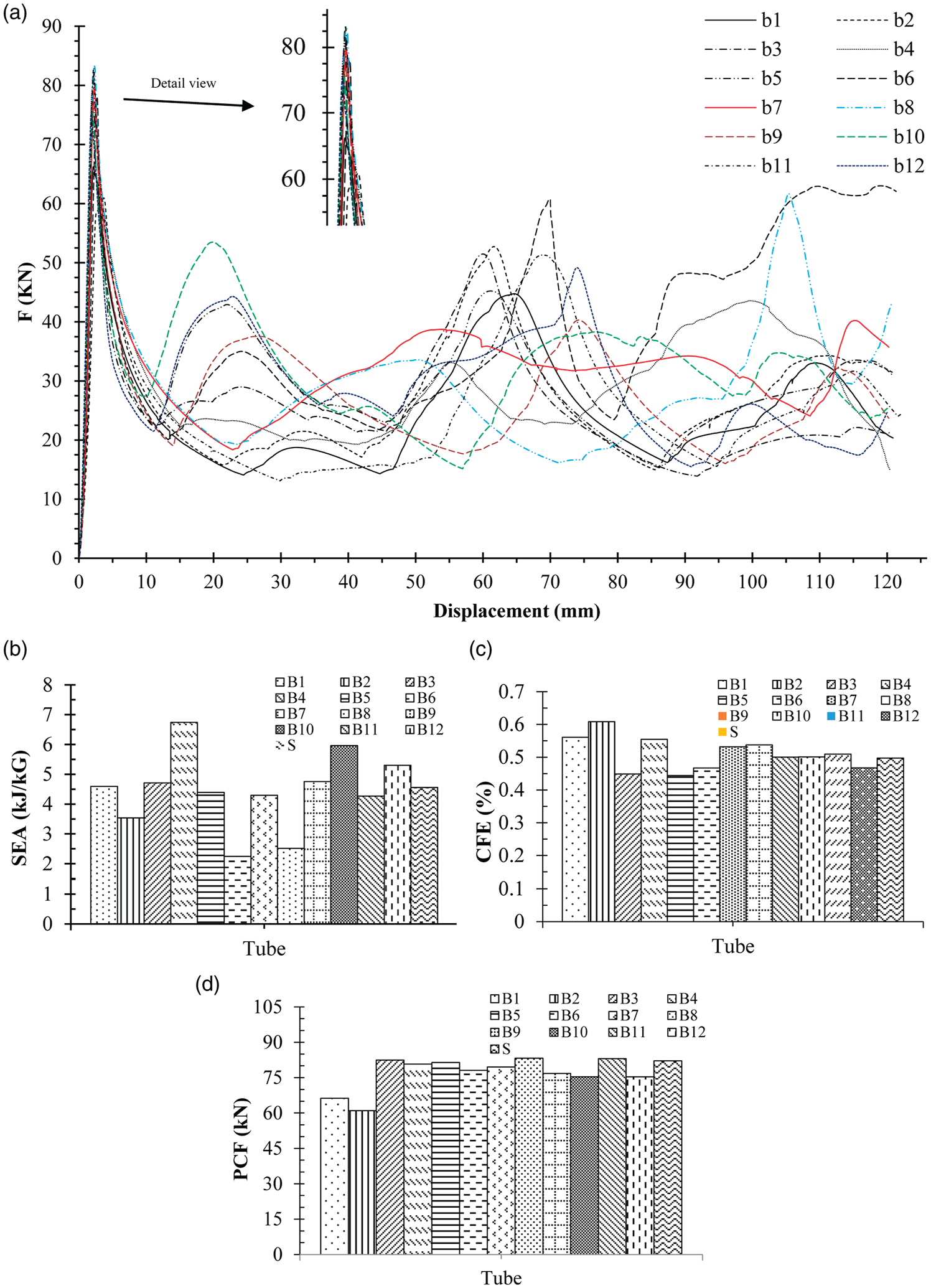
Crashworthiness parameters of tubes: (a) Force-displacement curves, (b) SEA, (c) CFE, (d) PCF.
Figure 6(b) shows the SEA of the draw bead tubes and the square tube without draw beads, “S”. It is evident that the B4, B10 and B12 tubes with the vertical beads absorbed more energy in comparison to other designs. The draw bead tube B4 exhibited the best SEA compared to others. In particular, the SEA of the B4 tube was 200% and 48% higher than that of the B6 tube and normal square tube (S). Comparing the crush force efficiency as shown in Figure 6(c), the draw bead tubes designs with horizontal beads performed better compared to other tubes. In fact, the B2 tube exhibited the highest CFE with the value of 0.61, following by B1 and B4 tubes with a CFE of 0.56. Meanwhile, the B5 tube with the hybrid draw bead had the lowest CFE of 0.44 and the normal square tube had the CFE of 0.49. As a result, the introduction of the horizontal draw bead to the square tube can improve the CFE by up to 25% in comparison to the normal square tube. For the PCF (Figure 6(d)), the PCF of all the draw bead tubes was comparable within the same range and higher than that of the B1 and B2 tubes. Interestingly, the B1 and B2 tubes displayed the horizontal draw beads while other tubes exhibited the vertical draw beads, hybrid draw beads and one horizontal draw bead on each side of the tube. This means that the horizontal draw beads played an important role in reducing the PCF, especially, two draw beads for each side of the tube. When comparing to the normal square tube, the PCF of the B2 tube with the horizontal draw beads can reduce around 26%. This was due to the tubes beads formed horizontally and perpendicularly to the axial direction and the tube was easily buckled at the draw beads. The observed phenomenon also agreed with the previous finding for other triggering mechanisms for the tube such as corner dents (Ferdynus et al., 2019), window patterns (Nikkhah et al., 2019; Song et al., 2013). For a well-designed energy-absorbing system, a balance between SEA and PCF is often desired.
Figure 7 presents the 60% deformed shapes behavior for all the draw bead tubes under axial quasi-static loading. It can be seen that under axial loading all the tubes folded progressively. However, the tubes that beading in horizontal (B1-B2-B9-B11) have a more desirable symmetrical deformation mode. Analysing the deformation mode associated with B6-B10-B12 (Vertical bead formed) tubes, it can be seen that the underside of the tube is unsymmetrically crushed, and the interaction effect offered by the beading is minimal. The tubes also deformed with large hinges which increasing buckling resistance. Nevertheless, it can be seen that the crushing process can be controlled by the development of draw bead forming directions.
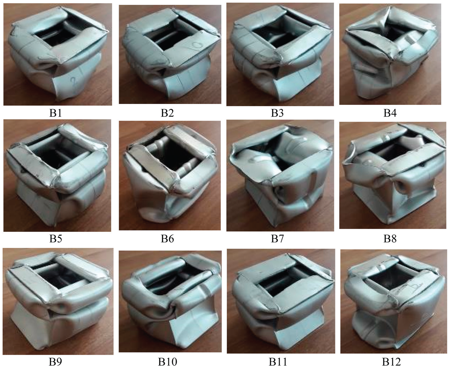
Draw bead square tubes under axial loading deformation modes.
Identifying the best configuration using the TOPSIS method
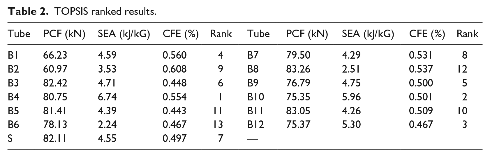
In the previous section, the crashworthiness of the proposed structures was assessed using separated crashworthiness parameters. For instance, if the lightweight and energy absorption capacity are the key characteristics for the energy absorbers, the SEA is an appropriate criterion for choosing the best energy absorber. Based on these criteria, the B4 tube was selected as the optimal structure among the tested structures. However, an excellent absorber requires a comprehensive evaluation of various crashworthiness parameters. Unfortunately, it is difficult to evaluate the energy absorption performance of these structures reasonably by considering all parameters because the mentioned parameters were mutually conflicted. To define the best tube with considering all of the crashworthiness parameters, the TOPSIS method was used. As could be seen in Table 2, tube B4 is the best in overall performance while the B6 tube has the lowest ranking. The reason is that the B4 tube has combined horizontal and vertical beads at the top and bottom ends in each side of the tubes to achieve the efficient crushing behavior with low initial peak force and high energy absorption as shown in Figures 6 and 7.
TOPSIS ranked results.
The effect of forming direction of the bead draw tubes
The draw bead tubes can be formed in the outside and inside of the tubes and it can play an important role in the crashworthiness, especially, their influence on crushing behavior and energy absorption is more comparatively. In this section, the tube with the highest score in the Identifying the best configuration using the TOPSIS method section (B4) was chosen to investigate the effects of different forming directions of the draw beads (Figure 8). The geometry configuration of the tubes was the same as the tubes shown in Figure 1.
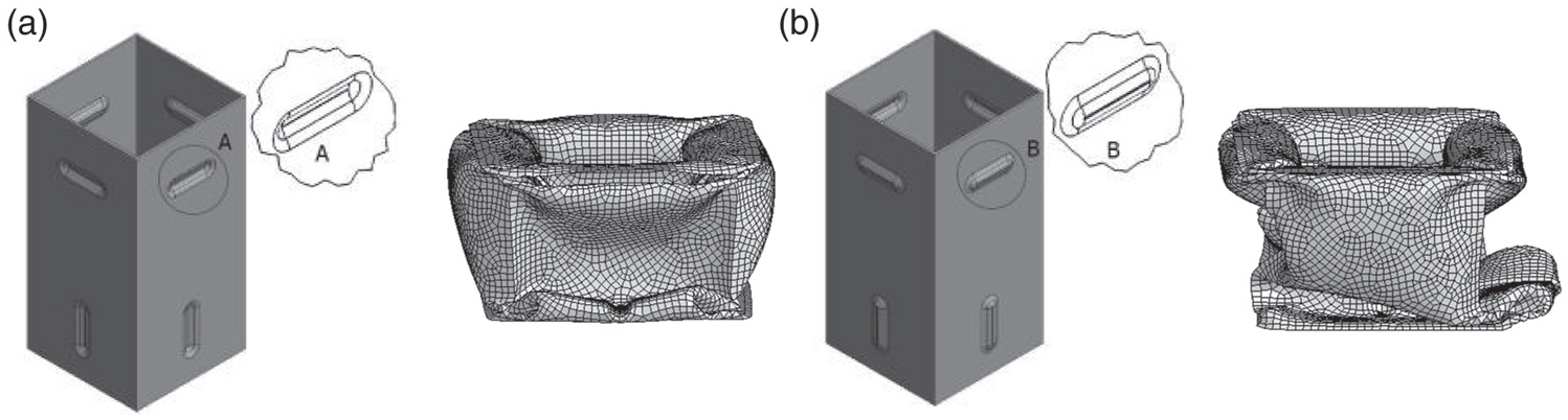
Forming direction and deformation modes of draw bead tubes: a) Inside direction formed tube (B4), b) Outside direction formed tube (B4O).
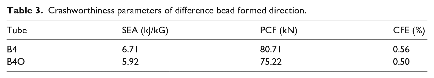
The effect of forming direction on crashworthiness parameters such as SEA, PCF, and CFE is analyzed under axial quasi-static loading, as shown in Table 3. The tube with outside direction formed (B4O) required low energy to crush due to the tendency to deform outside in the square tubes. The deformation mode of the B4O tube absorbed low SEA and PCF. The CFE of the B4O tube was also less than that of the B4 tube. From the numerical result, the forming direction of the draw bead can control the PCF and is helpful for the design of energy absorbers. Therefore, the selection of the type of the tube depends on the crashworthy application which requires less impact force or high energy absorber.
Crashworthiness parameters of difference bead formed direction.
Conclusion
In this paper, crashworthiness and energy absorption characteristics of draw bead structures with various configurations were studied. To investigate the effect of the forming history on crashworthiness, the sheet metal was formed by the bead drawing process. The tubes investigated numerical using the nonlinear finite element codes LS-DYNA/explicit and experimental tests under quasi-static loading. The results showed that forming history influenced the crashworthiness of the tube. With bead draw results mapped to the tube, energy absorption increased by 48%, peak crushing force decreased by 26% and crush force efficiency increased by 25% in comparison to the square tube without the draw bead, “S”. Finally, the best tube scored according to TOPSIS results was selected to investigate the effect of forming direction of the bead draw tubes. It is shown that the B4 tube absorbed more energy than the B4O tube and had high crush force efficiency.
There are some ideas about the different configurations of draw bead formed tubes. New study can be done by changing the size of the bead shapes, bead length and the effect of the depth of the draw beads on the crashworthiness metrics under axial and oblique loading conditions. This study can contain a fully parametrical shape optimization analysis method using optimization algorithm like simulated annealing.
Footnotes
Acknowledgements
The authors acknowledge with grateful appreciation the kind assistance and technical support provided by Dr Arameh Eyvazian (Department of Mechanical and Industrial Engineering, Qatar University, Qatar).
Declaration of conflicting interests
The author(s) declared no potential conflicts of interest with respect to the research, authorship, and/or publication of this article.
Funding
The author(s) received no financial support for the research, authorship, and/or publication of this article.