
Abstract
This paper investigates the blast-resistant behavior of Ultra-High Performance Fiber-Reinforced Concrete (UHPFRC) slabs through close-in detonation tests. The UHPFRC was produced using locally sourced materials from Vietnam. A total of five slabs, with varying volume fractions of steel fibers ranging from 0% to 3%, were tested. Four of the slabs incorporated steel mesh, while one slab contained 2% steel fibers without steel mesh. All slabs had identical dimensions, measuring 1000 mm in length, 1000 mm in width, and 60 mm in thickness. The blast effect was simulated using a TNT explosive with a mass of 0.55 kg. Close-in detonation tests were conducted, and the resulting slab damage was measured and analyzed. The performance of the UHPFRC slabs was assessed using two key metrics: damage and blast resistance coefficients. The test results indicated that the level of damage in slabs exposed to blasts can be reduced by incorporating steel fiber content ranging from 1% to 3%. Moreover, slabs with 2% steel fiber content in UHPFRC, fabricated using local materials, exhibited both high blast resistance and cost-effectiveness. Additionally, the inclusion of steel mesh helped reduce damages in UHPFRC panels subjected to close-in detonations. The experimental results presented in this paper provide valuable insights into the behavior of UHPFRC slabs with varying fiber content when subjected to close-in explosions and can serve as a basis for future calculations and research.
Keywords
Introduction
Normal-strength concrete has long been a preferred material for constructing bridges, buildings, and other engineering structures. However, when an explosion occurs near concrete structures, whether intentional or accidental, the consequences can be devastating. Explosions can cause significant damage to both the material and the entire structure, potentially leading to collapse (Ngo et al., 2007). To mitigate the impact of blast loads, it is essential to understand how concrete behaves under such extreme conditions and develop more effective solutions.
The recent development of Ultra-High-Performance Fiber-Reinforced Concrete (UHPFRC), an innovative material that surpasses normal-strength concrete in terms of strength, ductility and toughness, offers potential solutions for resisting blast loads. Thanks to the inclusion of high-pozzolan components such as silica fume and the incorporation of steel fibers, UHPFRC achieves excellent compressive strength, typically exceeding 120 MPa, along with outstanding fracture toughness. Additionally, it can attain flexural strength greater than 40 MPa. Given these superior properties, many studies have been conducted to investigate the behavior of UHPFRC structures under explosive loading.
A number of studies have been conducted to investigate the behavior of UHPFRC panels under contact-detonation conditions (Le et al., 2020; Li et al., 2015b; Millard et al., 2010; Peng et al., 2019; Yao et al., 2019). However, non-contact explosions have also garnered significant attention due to their large impact radius, which can affect many surrounding structures. In state-of-the-art research on the blast performance of UHPFRC slabs under blast loading, the focus has been on non-contact explosions, the effects of fiber content and reinforcement on blast resistance, and the determination of optimum fiber content. Wu et al. (2009) conducted a series of tests to examine the performance of several types of concrete under blast loading conditions. The main parameters included explosive charge sizes, scaled distance, and steel reinforcement ratio. The study found that plain UHPFRC slabs without steel mesh exhibited similar resistance to blast loads when compared to normal reinforced concrete (NRC) slabs with steel mesh, embedded in both major and minor bending planes. Additionally, the inclusion of externally bonded FRP applied to the compression face of NRC slabs improved their ductility and blast resistance.
In addition, Kim et al. (2010) conducted tests on six specimens, including two made from normal strength concrete (NSC), two cast using ultra-high strength concrete (UHSC), and two reactive powder concrete (RPC) slabs. All tested panels were subjected to a 28.7 lbs. (13.02 kg) TNT explosive charge, with a constant standoff distance of 1.5 m from the specimens to the midpoint of the explosive charges. Specimen acceleration, displacement behavior, and concrete strains were measured. The study showed that UHSC and RPC specimens exhibited superior performance in blast resistance compared to NSC slabs, with increases in resistance ranging from 30.9% to 35.9%. Later, Mao et al. (2014) numerically investigated the effectiveness of steel reinforcement and steel fibers in UHPFRC, considering different blast scaled distances, from close-in to far-field scenarios. The authors observed that, under far-field blast loading, reinforcement bars and steel fibers contributed similarly to the blast resistance of the UHPFRC panel. However, under near-field loading, the blast resistance of UHPFRC slabs significantly increased with the addition of steel reinforcement bars. In a subsequent study, Mao et al. (2015) investigated the behavior of small-scale UHPFRC slabs (660 × 660 × 25 mm) under close-in explosions. The authors examined the effects of fiber content and fiber types, using 13 mm and 25 mm long fibers with volumetric content ranging from 2% to 6%. Peak ¼ span deflections and damages were monitored, and numerical studies were subsequently performed. The results showed that the two types of investigated steel fibers had similar effects on blast resistance. Additionally, the increase in fiber content resulted in improved blast resistance. Later on, Foglar et al. (2017) conducted full-scale tests on high-performance fiber-reinforced concrete (HPFRC) and UHPFRC bridge decks subjected to near-field blast loading. Fiber length (13 mm and 30 mm) and fiber content (up to 120 kg/m3) were main variables. The results confirmed the positive effect of increasing fiber content and compressive strength on the blast resistance of the specimens.
In a more recent study, Konrád and Sovják (2019) examined the ability of UHPFRC concrete to absorb and dissipate energy under impact loading. Volumetric fiber fractions ranging from 0.125% to 2% were investigated. A high-speed camera was used to monitor the impact of UHPFRC specimens before and after contact. The study observed significant differences in dissipation energies for varying fiber contents and loading rates. Next, Mai et al. (2020) conducted numerical studies based on a validated finite element model to examine the effect of slab thickness and steel reinforcement ratio on the blast performance of UHPFRC panels subjected to far-field explosions at different scaled distances. The study demonstrated that the failure mode shifted from shear to flexure as slab thickness decreased. Furthermore, the steel reinforcement ratio had a greater effect on the resulting maximum mid-span deflection in medium-range explosions compared to far-field explosions. Additionally, Sherif et al. (2020) used the finite element method to optimize the design of UHPFRC with a strength of 200 MPa under blast loads at a scaled distance of 0.80 kg/m1/3. The design variables included slab thickness (ranging from 100 mm to 300 mm), reinforcement ratios of 0%, 0.2%, 1%, and 3%, and aspect ratios of 1, 1.5, and 2. The results indicated that a slab thickness of 150 mm was optimal for cost-effectiveness under the testing conditions. Furthermore, the optimal shape for the panels to withstand blast loading was rectangular, with an aspect ratio of 1.75. The study also confirmed the effectiveness of reinforcement in improving the blast resistance of UHPFRC panels.
Recently, Su et al. (2021) studied the behavior of ultra-high-performance concrete (UHPC) slabs under medium-range explosions, with scaled distances ranging from 0.5 m/kg1/3 to 1 m/kg1/3. Bending failure was observed in the tests of one-way slabs subjected to medium-range explosions. Additionally, the damage to the panels increased as the scaled distance decreased. The study also demonstrated the superior performance of UHPC panels compared to normal-strength concrete panels under explosive loading. Furthermore, Liao et al. (2022) examined the behavior of ultra-high ductile concrete (UHDC) and UHPC under close-in blast loading. The authors investigated the effects of fiber types, reinforcement ratios, and scaled distances on the blast resistance of the tested UHDC and UHPC slabs. The experimental study showed that no cratering or punching shear failure occurred on the surfaces of the UHPC slabs. Local damage in UHDC/UHPC slabs with reinforcement was nearly eliminated due to the ultra-high compressive strength of the investigated materials. More recently, Abedini and Zhang (2024) utilized a verified finite element (FE) model to investigate the behavior of NSC and UHPFRC panels under explosive loading. The degree of vulnerability of the panels was obtained and compared. The study confirmed the superior performance of UHPFRC compared to NSC in withstanding blast loading by reducing both residual and maximum displacement, increasing energy absorption, and enhancing damage tolerance. In addition to the studies presented, several other investigations have explored the effects of slab thickness, concrete type, fiber mix proportion, tensile longitudinal reinforcement, and impulse load magnitude on the blast resistance of UHPFRC panels (Li et al., 2015a, 2024; Wu et al., 2009). A more comprehensive review of the behavior of UHPFRC members under blast loads can be found in Hao et al. (2016) and Liu et al. (2024).
The review of relevant studies on the behavior of UHPFRC slabs subjected to blast loads highlights that, while several authors have investigated the effect of fiber content on blast resistance, there are few experimental studies on the performance of UHPFRC panels with varying fiber content under close-in blast conditions. Furthermore, the optimal fiber content for UHPFRC panels to effectively resist blast loads has not yet been fully analyzed. To address these research gaps, this experimental study was conducted. The primary objective of this research is to experimentally examine the blast resistance of UHPFRC panels, fabricated from locally sourced materials in Vietnam, under close-in explosions, and to identify the optimal fiber content for enhanced blast resistance. The study also aims to assess the advantages of UHPFRC compared to normal concrete (NC) and establish a foundation for further research and application of UHPFRC in specialized projects across Vietnam.
The paper begins by outlining the process of producing specimens. It is important to note that the UHPFRC mix was prepared in the laboratory using materials that are readily available in Vietnam. The following section describes the explosive tests conducted on the specimens. The experimental program involved four UHPFRC slabs with varying fiber fractions (1%, 2%, and 3%) and one normal concrete (NC) slab. All slabs measured 1000 mm in length, 1000 mm in width, and 60 mm in thickness. TNT explosives were used for the tests. The results are presented, with observations and findings discussed in the final section, which focuses on the crater and spall damage observed on the specimens subjected to close-in explosions. A comparison is also made between the performance of UHPFRC and NC slabs in these aspects. Additionally, the effect of varying fiber volume fractions was examined to determine the most effective approach for enhancing the blast resistance of UHPFRC panels. It should be noted that the study focused on the cracks and damage of slabs with different fiber contents and reinforcement ratios, and no displacement or overpressure was monitored during the tests. This is one of the limitations of this study.
Preparing the specimens
Concrete mix
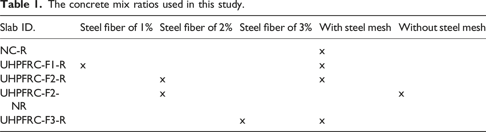
The concrete mix ratios used in this study.
The mix design for 1 m3 concrete used in this study.
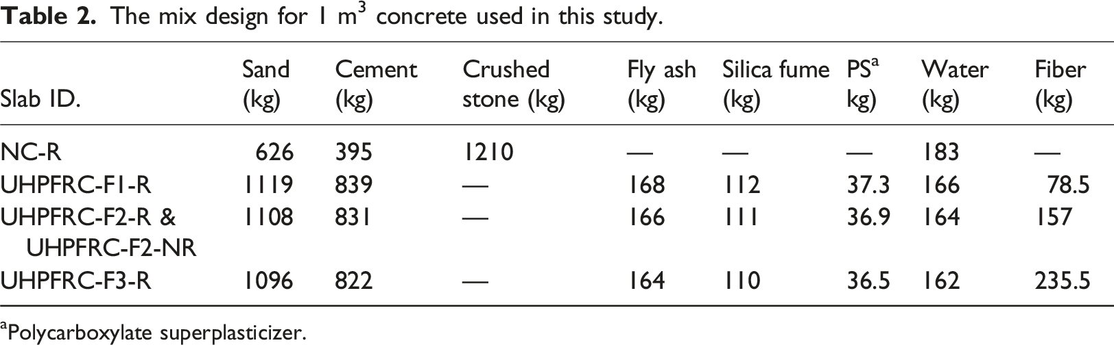
aPolycarboxylate superplasticizer.
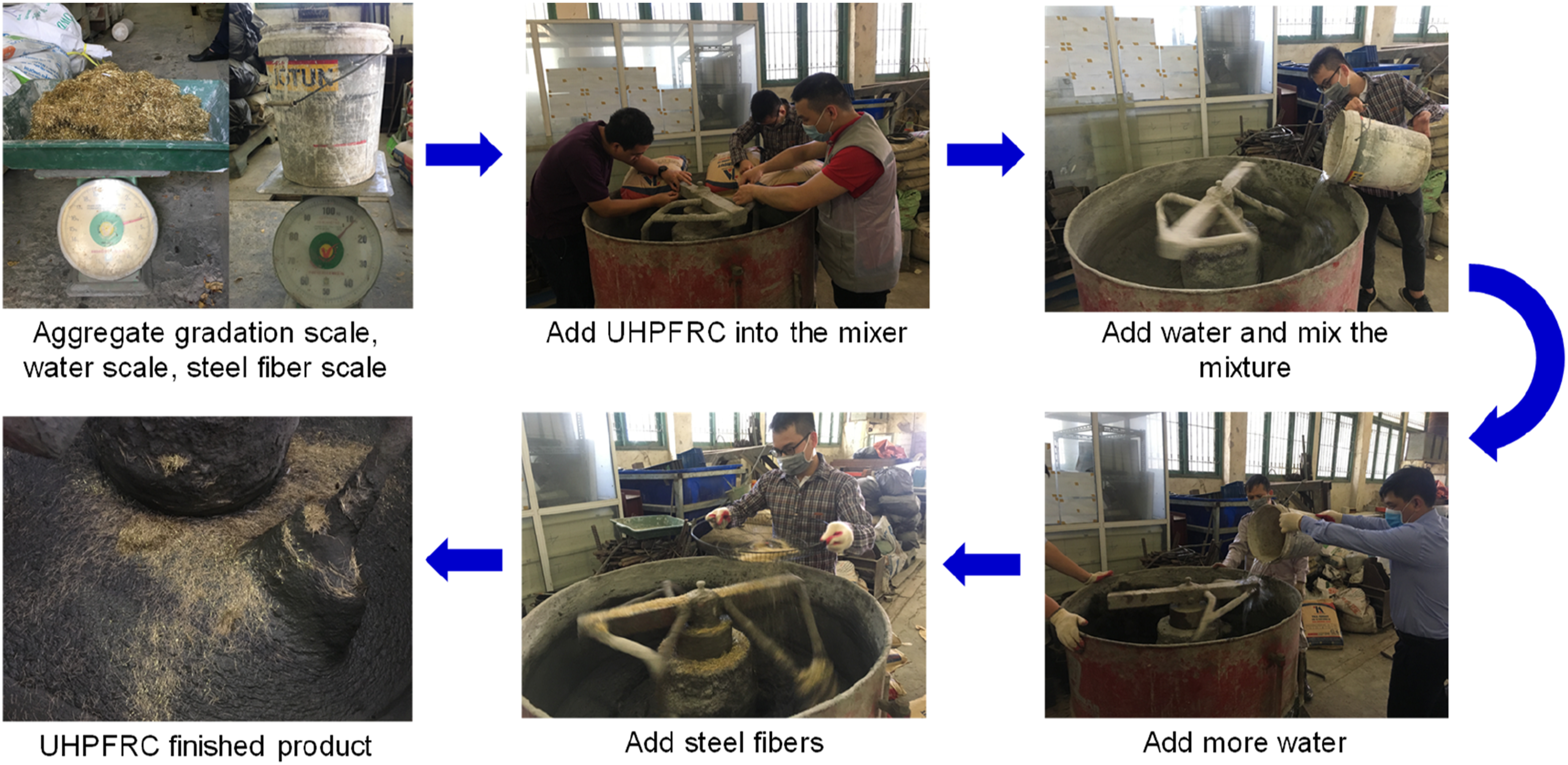
The process of manufacturing UHPFRC.
Specimens manufacturing
For the field blast tests, one NC slab and four UHPFRC slabs were fabricated. The specific layout and dimensions of the slabs are shown in Figure 2(a). As illustrated in Figure 2(a), all the slabs had dimensions of 1000 × 1000 × 60 mm (length × width × thickness). One layer of steel mesh positioned 20 mm from the bottom slabs’ soffit was incorporated into the four slabs stated in Table 1. The steel mesh consisted of 10 bars, each with a dimension of 6 mm at spaced 90 mm apart (Figure 2(b)). The nominal yield strength of the steel reinforcement was 400 MPa. Figure 3 presents the mixing and casting the UHPFRC slabs. During the casting process, it is important to ensure proper compaction to eliminate any air voids. Specimen dimensions and reinforcement layout. (a) The specimen dimensions. (b) Reinforcement arrangement and formwork installation. Pouring concrete into formwork and completing the experimental specimen. (a) Pouring of UHPFRC mixtures. (b) Smoothing the surface and finishing the specimen.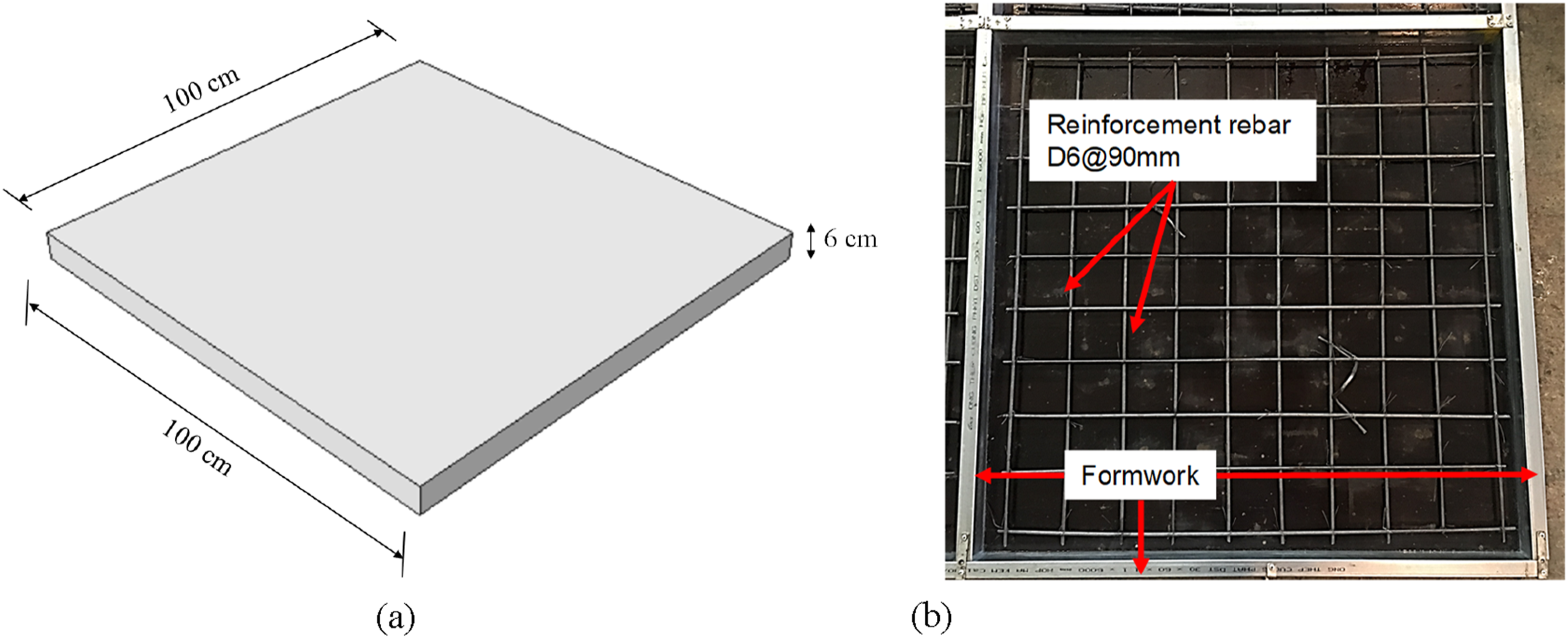
Material properties
Properties of concrete from material tests.
Setup for experimental blast testing and possible damage modes
Test setup
A total of five blast tests were conducted on one NC slab and four UHPFRC slabs to evaluate their performance under non-contact explosion conditions. For each blast test, the slab specimen was placed on the test site using a testing rig made of steel frame, which provided support on two sides of each slab (Figure 4). The detailed dimensions of the rig are shown in Figure 4. All the tests were conducted using a TNT charge with a cylindrical shape, having a height of 167 mm, a diameter of 51.5 mm, and a TNT density of 1.59 g/cm3, which corresponded to an equivalent of 0.55 kg of TNT. The explosive charge was placed above the center of the slabs (in plan view), positioned 50 mm below the upper soffit of the slabs (as shown in Figure 5). An electric detonator was employed to initiate the explosive charge in this setup. Upon detonation, the explosives rapidly transform from a solid state to gas, interacting with and transferring energy to the surrounding areas and applying loads on the tested slabs. The dimensions of the steel supporting frame and experimental setup. Placement of a 0.55 kg explosive block 50 mm below the top soffit of the Slab.

Possible damage modes
The scaled distance Z, an important concept in blast testing, is often used to assess the potential impact of a blast on surrounding structures or environments. It is commonly determined based on the actual distance from the mass of the explosion to the point of interest (R) and the TNT equivalent charge weight (W). According to the Hopkinson-Canz (Krauthammer, 1999), the scaled distance, can be estimated as follows:
From equation (1), a value of Z in this study is 0.16 m/kg1/3, which is smaller than 1.19 m/kg1/3. Therefore, the experiment is classified as close-in detonation (Smith et al., 2009). In close-in explosions, the blast wave effects result in compression on the exposed face, while the opposite face experiences tensile damage (Botez and Bredean, 2019). Four different types of damage modes, including cratering, collapse, perforation, and punching (Figure 6) may occur (Zhang et al., 2006). Cratering damage is characterized by damage limited to the front surface, with no scabbing on the rear face. Collapse damage involves cratering on both the front and rear faces but without perforation of the slab. Perforation represents the most severe damage, where the front crater extends through the rear crater. In cases of extremely powerful detonation shock, the slab may experience shear plugging, causing the entire damaged area to be forcefully pushed outward (Yao et al., 2019). The common damage mode of concrete slabs caused by a non-contact explosion (Zhang et al., 2006).
Experimental results and analysis
Test results
The combined results of crater diameter and crater depth for the slabs on both sides.
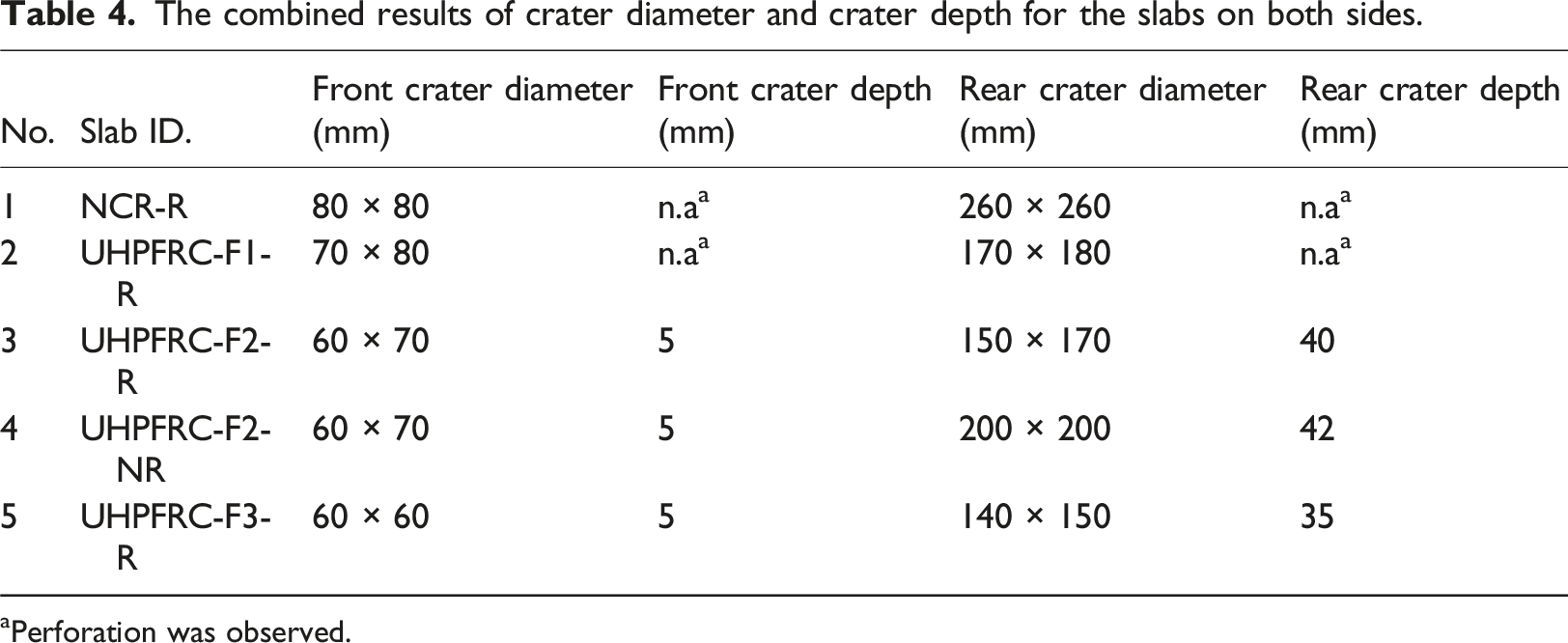
aPerforation was observed.
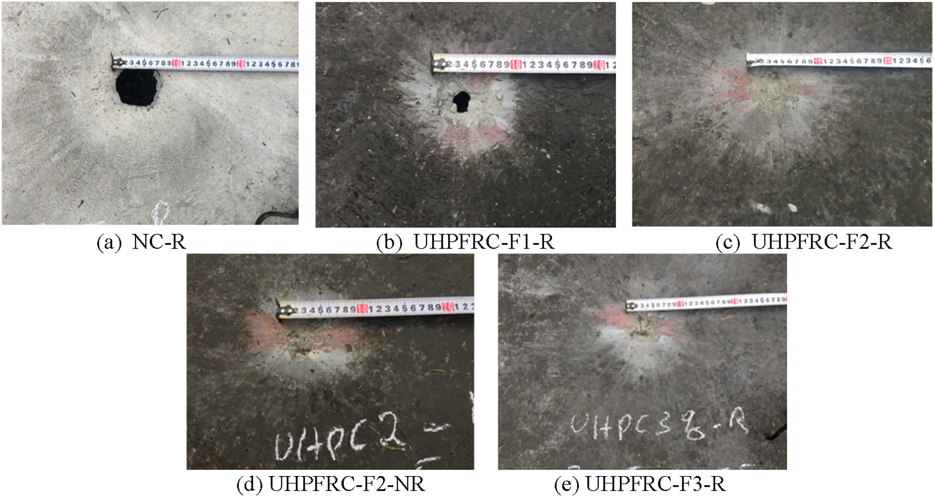
The damage at the front face of the tested slabs. (a) NC-R. (b) UHPFRC-F1-R. (c) UHPFRC-F2-R. (d) UHPFRC-F2-NR. (e) UHPFRC-F3-R.
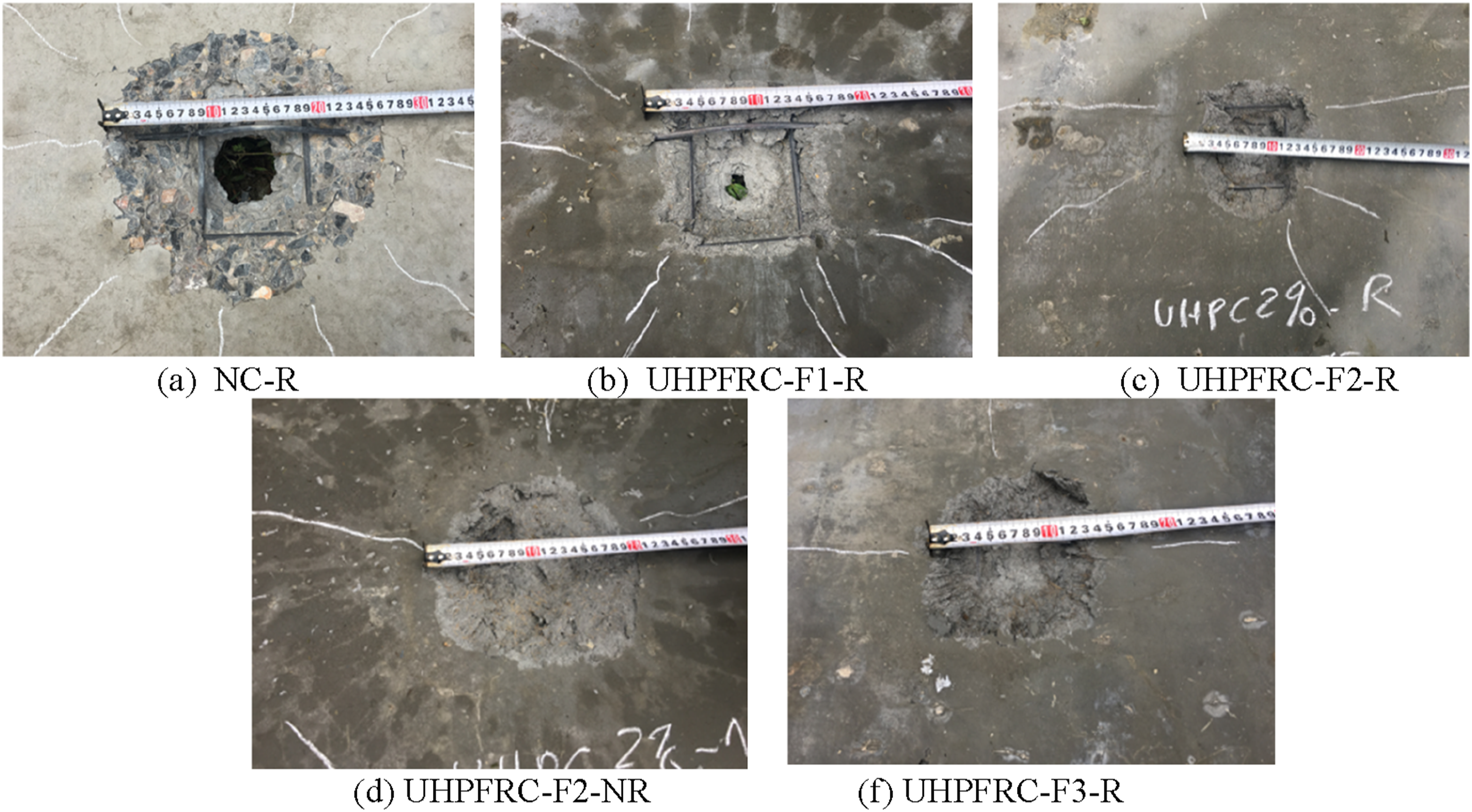
The damage at the rear face of the tested slabs. (a) NC-R. (b) UHPFRC-F1-R. (c) UHPFRC-F2-R. (d) UHPFRC-F2-NR. (f) UHPFRC-F3-R.
Based on the measured values shown in Table 4 and the damage observed in the tested slabs, as depicted in Figures 7 and 8, it is evident that the NC-R slab sustained more severe damage compared to the other four slabs containing steel fibers. These observations confirm the effectiveness of steel fibers in resisting blast loading, as demonstrated in previous studies (Li et al., 2015a; Liao et al., 2022; Yao et al., 2019). The superior performance of UHPFRC slabs, compared to the NC slab, can be attributed to their significantly enhanced properties in terms of strength, energy absorption, and durability. These improvements are achieved by minimizing porosity, increasing density, and incorporating rational amounts of fibers (Zhong et al., 2021).
The damage observed on the front and rear surfaces of the tested slabs (Figures 7 and 8) indicates that the primary types of damage were local collapse and perforation. It is important to note that, in these tests, local collapse refers to the formation of cratering on both the front and rear faces of the specimen without perforation, as illustrated in Figure 6 (Zhang et al., 2006). These damage modes are also consistent with those observed in previous blast tests on concrete panels (Wang et al., 2013; Xiao et al., 2024). Such damages typically result from local spalling and scabbing that are associated with the effects of shock and reflected waves during an explosion (Jaini et al., 2016). While the three slabs with a volumetric steel fiber content of 2% or greater only exhibited cratering on both faces, the two slabs with 1% steel fiber and the slab without steel fibers showed perforation, resulting in more severe damage. This can be attributed to the role of steel fibers in UHPFRC, which significantly enhances the material’s performance under explosive loading. Steel fibers are known to control crack formation and propagation (Pyo et al., 2016). Under the intense pressures of a blast, cracks and spalls typically form in concrete. However, steel fibers act as crack arresters, preventing cracks from spreading or growing larger, and helping to hold the material together, thereby reducing spalling. These beneficial effects are not observed in concrete with low or no fiber content.
The test results also indicate that the front faces of the slabs exhibited similar crater sizes, while the differences became more pronounced on the rear faces. Additionally, the dimensions of the craters on the rear faces were significantly larger than those on the front surfaces. This phenomenon can be attributed to concrete’s much higher compressive strength compared to its tensile strength. When a shock wave impacts the slab, it generates compressive forces on the top surface and tensile forces on the bottom, leading to more severe damage on the rear face. This observation is consistent with findings from several studies in the literature (Botez and Bredean, 2019; Wang et al., 2013; Yao et al., 2019).
Regarding the number of cracks, the rear face of the slabs predominantly exhibits cracking, while the front face shows minimal signs of cracking. This phenomenon can be attributed to the concrete’s significantly higher compressive strength compared to its tensile strength. When a shock wave impacts the slab, it generates compressive forces on the top and tensile forces on the bottom. Figure 9 shows the cracks on the rear face of the slabs, revealing that all cracks are radial in direction. Radial cracks were also observed in several studies, such as those by Wang et al. (2013) and Botez and Bredean (2019). These cracks occur due to a combination of reflected waves and dynamic vibrations from the explosion, resulting in cracks propagating from the epicenter towards the free edges (Jaini et al., 2016). The NC-R slab displays the highest number of cracks, with long fissures extending across its entire rear face. In contrast, UHPFRC-F2-R and UHPFRC-F3-R show fewer cracks, indicating that UHPFRC possesses a higher tensile strength limit. Additionally, the increased fiber content contributes to enhanced crack resistance within the structure (Figure 9). Diagram of cracks on the rear face of the slabs.
Comparison between NC and UHPFRC slabs
To evaluate the effectiveness of UHPFRC slabs with different fiber contents, the damage levels of four tested slabs incorporating steel mesh, that is, NC-R, UHPFRC-F1-R, UHPFRC-F2-R, and UHPFRC-F3-R with fiber contents of 0%, 1%, 2%, and 3%, respectively, were compared. The test results presented indicate that while the NC-R and UHPFRC-F1-R slabs, with steel fiber contents of 0% and 1%, respectively, experienced complete perforation (the most severe form of local damage), the UHPFRC-F2-R and UHPFRC-F3-R slabs, with steel fiber contents of 2% and 3%, exhibited significantly less severe damage. This demonstrates the effectiveness of incorporating steel fibers at concentrations of 2% and 3% to enhance blast resistance.
Figure 10 compares the size of the front and rear craters for each examined slab. As shown, a decreasing trend in crater sizes was observed from NC-R to UHPFRC-F1-R, UHPFRC-F2-R, and UHPFRC-F3-R for both the front and rear faces. The crater diameters on both the front and rear faces of the NC-R slab are significantly larger than those of the UHPFRC slabs. While both the NC-R and UHPFRC-F1-R slabs exhibit holes, the hole size in the UHPFRC-F1-R slab is considerably smaller (Figures 7 and 8). Notably, the UHPFRC-F2-R and UHPFRC-F3-R slabs show no holes (Table 4). For the rear surface, the crater diameter of the NC-R slab is 26 cm, approximately 1.5 times larger than that of the UHPFRC-F1-R, UHPFRC-F2-R, and UHPFRC-F3-R slabs, which measure 18 cm, 17 cm, and 15 cm, respectively. The width and depth of the craters in structures subjected to explosive loads are critical factors, as they directly impact the safety of individuals sheltering inside or behind them. Larger damage sizes can result in larger fragments, increasing the danger and posing a higher risk to human lives. This not only demonstrates the superior blast resistance of UHPFRC compared to NC-R but also highlights the reduced risk to human health from flying fragments when UHPFRC is used. Sizes of front and rear craters of the tested slabs with a steel mesh after testing.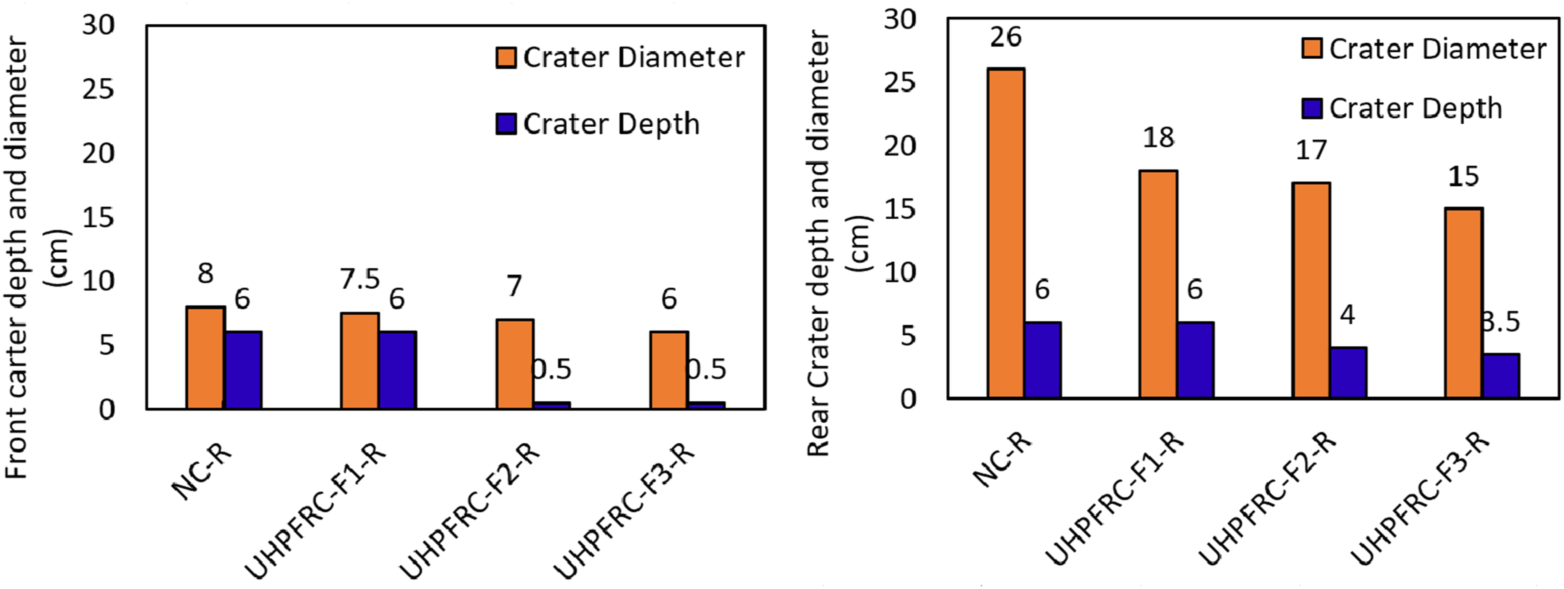
In summary, the damage modes and patterns observed in the four slabs indicate that UHPFRC material exhibits significantly higher blast resistance compared to NC. The UHPFRC slabs showed less damage, fewer cracks, and much smaller expansions compared to the NC slab. This improved performance can be attributed to the role of steel fibers in UHPFRC, which act as bridges connecting the cracks, thereby reducing both their number and their width. Additionally, the relatively fewer cracks in the UHPFRC slabs suggest that repairing blast-damaged UHPFRC structures would require less effort and cost compared to repairing NC structures.
Effect of steel mesh on blast resistance and optimizing fiber ratio for UHPFRC
Steel fibers play a crucial role in enhancing the tensile strength of concrete. Both the fiber volume fraction and the type of steel fibers significantly influence the tensile and compressive mechanical properties of UHPFRC under dynamic loading (Gao et al., 2022; Sun et al., 2023). Additionally, factors such as fiber geometry, packing density, and volume fraction that enhance energy dissipation are essential for optimizing the blast performance of UHPFRC panels (Xu et al., 2023). Therefore, determining the optimal fiber volume fraction not only strengthens structural integrity but also mitigates damage from blast loading, highlighting its critical importance in structural design.
This section investigates the optimal steel fiber volume fraction by analyzing four UHPFRC slabs. These slabs include two with volumetric fiber contents of 1% and 3%, and two with a 2% fiber volume fraction, one incorporating steel mesh and the other without. Figure 10 illustrates the damage to UHPFRC slabs with different steel fiber volume fractions resulting from the explosion of a 0.55 kg explosive charge on the front and rear surfaces. In this experiment, UHPFRC-F1-R exhibited significant damage, leading to the formation of holes, while the remaining UHPFRC slabs experienced less severe damage and did not show any holes (Figures 7 and 8).
To quantitatively assess the level of damage, the damage coefficient Damage coefficient Ka and blast-resistant coefficient Kb.

The results for the
The
In summary, the blast resistance of UHPFRC improved with an increasing volume fraction of steel fibers, ranging from 1% to 3%. However, the enhancement in effective blast resistance became negligible when the fiber volume fraction increased from 2% to 3%. Therefore, a 2% fiber volume fraction in UHPFRC, made with locally sourced Vietnamese aggregates, is optimal for balancing both high blast resistance and cost-effectiveness. Furthermore, the use of steel mesh is crucial for further reducing damage levels.
Conclusions
This paper presents experimental investigations of four UHPFRC slabs and one NC slab subjected to close-range blast loading, using locally sourced materials from Vietnam. The results demonstrate that the UHPFRC slabs exhibit significantly higher blast resistance compared to the NC slab. Based on observations from the tests and subsequent analyses, the following key findings are highlighted: - For UHPFRC slabs with steel fiber content ranging from 1% to 3%, similar to those tested in this study, the level of damage decreased as the steel fiber content increased. - The incorporation of steel mesh in UHPFRC panels was essential for reducing surface damage under tensile forces. - The evaluation of the optimal steel fiber content indicates that a 2% steel fiber content in UHPFRC panels produced using locally sourced Vietnamese materials, achieves an ideal balance between enhanced blast resistance and cost-effectiveness.
These findings offer valuable insights for future design calculations and research, providing a solid foundation for the application of UHPFRC in specialized projects that require robust resistance to blast loads and impacts, particularly in defense-related contexts.
Footnotes
Declaration of conflicting interests
The author(s) declared no potential conflicts of interest with respect to the research, authorship, and/or publication of this article.
Funding
The author(s) disclosed receipt of the following financial support for the research, authorship, and/or publication of this article: This research is conducted with the financial support of the Ministry of Education and Training under grant number B2023-XDA-05.