
Abstract
Ultra-High-Performance Concrete (UHPC) is a widely researched material with varied Civil and Military applications for resilient infrastructure. Design and assessment of UHPC members against ballistic impact of in-service ammunitions is critical to their application to protective structures. Experimental tests are necessary for performance verification and the numerical tools are required to assist with the design. This paper presents experimental and numerical studies on small-scale UHPC panels reinforced with steel fibres (UHPFRC) subjected to steel-inset projectiles. Benchmark concrete slabs with the same geometric parameters made from normal-strength concrete (NSC) were tested to compare the performance of UHPFRC against NSC. The perforation limit thickness of UHPFRC and NSC slabs against steel-inset bullets were determined. The enhanced impact resistance of UHPFRC compared to NSC in terms of depth of penetration (DOP) as well as crater area is most effectively utilized against repeated impacts which is crucial for protective structures. Finite element (FE) models of the slabs were developed and validated against experimental results. An empirical equation to predict DOP was developed with a dimensional analysis of the data collected through experiments and numerical results. The equation can reliably predict the DOP of a UHPFRC panel subjected to impact from deformable steel-inset ammunition of 7.62 mm calibre.
Keywords
Introduction
The landscape of weapon lethality has grown significantly in the last few decades with improved electronics and composite materials. However, the protective structures are still designed with conventional materials like structural steel and reinforced concrete. Such structural systems often tend to be large and time-consuming to construct and at the same time cannot provide adequate protection against increasingly lethal weapons. For example, the military bunkers and hardened shelters are now more vulnerable due to the advent of loitering ammunition, that provides a cheaper and more accurate means of targeting the shelters, that were mainly designed to resist air-blast and low-velocity impact loads. Therefore, there is a need to improve the protection level of such structures using high performance materials with significantly enhanced material properties than normal strength concrete (NSC) and steel reinforcements.
Several past studies have tried to develop concrete with enhanced performance. Richard and Cheyrezy (1995) used components with increased fineness and reactivity to develop reactive powder concrete (RPC) through thermal treatment. Later, De Larrard and Sedran (1994) introduced the term ultra-high performance concrete (UHPC) for products with similar properties. Since then, many infrastructure projects have implemented UHPC as a construction material globally (Fehling et al., 2014). UHPC is a class of engineered cementitious composites that usually have compressive strength above 120 MPa, a tensile strength of 12-18 MPa, a water-binder ratio between 0.16 and 0.22, and high content of binder and fibres to improve ductility (ASTM C1856, 2017). A typical UHPC contains a high amount of cement content with or without supplementary cementitious materials (SCM), like micro-silica (MS), ground granulated blast furnace slag (GGBFS), ultra-fine GGBFS, crushed stone sand (CSS), quartz sand (QS) and quartz powder (QP). In most cases, steam or autoclave curing was adopted to increase the hydration rate and the pozzolanic activity of SCMs, thus giving a dense microstructure. So, most of the application of UHPC was restricted to precast industries. The idea of using UHPC is appealing for construction of protective structures for defence applications. However, such structures are often constructed in resource-constrained forward areas where advanced materials and specialized curing techniques may not be available. Hence, there is a need to develop UHPC using widely available materials under normal curing conditions, which could be used for large scale constructions in remote areas suited for defence applications.
Past research studies have shown the efficacy of using these engineered products specifically for high-strain-rate events like ballistic impact and blast loading. Unosson and Nilsson (2006) examined the behaviour of high-performance concrete (HPC) with compressive strength 153 MPa against high-velocity impact of steel projectiles. Plain and reinforced cylindrical samples of concrete were subjected to impact velocity of ∼620 m/sec. The damage response of the target was noted in terms of depth of penetration or exit velocity and the numerical simulation showed strong agreement with experimental results in case of perforation of target. However, in case of target penetration, the numerical computation results were not aligned with experimental results. Tai (2009) subjected UHPC and NSC panels to the high-velocity impact of flat-ended steel projectiles. The author reported that UHPC panels performed better in resisting the projectile impact; however, a brittle response was observed in panels without steel fibres. Therefore, it was reported that varying steel fibres content between 2 and 5 % improved the impact resistance of UHPC, evidenced by a decrease in depth of penetration (DOP) and scabbing area. Numerical simulations performed based on finite element code LS-DYNA (LSTC, 2017), showed agreeable results with the experimental data. Sovják et al. (2013) conducted experiments to find the optimum steel fibre content in UHPC to effectively resist projectile impact. Experimental trials were conducted with variation in fibre content from 0 to 3%. A reduction of 50% in crater diameter was observed for concrete with steel fibre content 2% by volume, however further increase in the fibre content was showed insignificant performance improvement. The response of NSC and UHPFRC slabs against high-velocity impact from hard steel projectile was investigated by Liu et al. (2018), where the authors suggested that the superior performance of UHPFRC makes it desirable material for military infrastructures.
The numerical simulation of ballistic impact to concrete slab is a challenging task due to complexity associated with modelling and unavailability of calibrated material models. Past numerical studies (Oucif et al., 2020; Pu et al., 2022; Tai, 2009; Tremblay et al., 2021; Unosson and Nilsson, 2006; Zhang et al., 2018) have primarily used the rigid projectile assumption for bullets, which may not be suitable for in-service ammunitions against concrete of very high strength. Additionally, the constitutive material models were developed to be utilized with NSC and requires comprehensive calibration and validation for application to ultra-high-performance fibre reinforced concrete (UHPFRC). Xu et al. (2020) recently presented a calibrated Karagozian & Case Concrete (KCC) (Malvar et al., 1997) constitutive model parameters to predict UHPC columns’ response to low-velocity impact. The KCC model for UHPC column was validated for drop hammer tests and triaxial compressive tests. Guo et al. (2018) reported that the KCC model has low accuracy in modelling impact-induced responses and presented a modified continuous surface cap model (CSCM) (Murray, 2007), which included strain rate parameters based on experimental results. The impact-induced experimental response agreed well with the numerically predicted response. Tremblay et al. (2021) developed a numerical model for UHPFRC slabs subjected to high-velocity impact from armour-piercing projectiles, where strength and failure of UHPFRC were represented using Riedel-Hiermaier-Thoma (RHT) (Borrvall and Riedel, 2011) model. It was noted that the numerical model was able to predict damage mode and crack patterns in UHPFRC slabs accurately. Further studies (Cui et al., 2017; Lai et al., 2021) have noted that RHT model can characterize concrete behaviour under high-velocity projectile impact. Dua et al. (2022) have also reported the influence of various keywords in LS-DYNA for accurately predicting high strain-rate response of concrete.
Although many research studies have investigated UHPFRC against impact loads, a comprehensive investigation on understanding the dynamic response of UHPFRC against military ammunition (steel-inset bullet) through experimental and numerical studies is sparse. This paper presents an experimental study on the response of 50 mm and 75 mm thick UHPFRC panels, and the results are benchmarked against NSC panels of the same thickness. The steel-inset ammunitions of 7.62 mm calibre were used for the tests. Furthermore, an experimentally validated LS-DYNA model is used to investigate the influence of various parameters such as projectile mass and velocity, compressive strength of concrete and thickness of target slab, on the response of UHPFRC panels. The experimental data and the numerical models are used to propose an empirical relationship to predict the depth of penetration of plain concrete slabs against deformable projectiles.
Development of UHPFRC
Mixture proportion of UHPFRC and NSC.
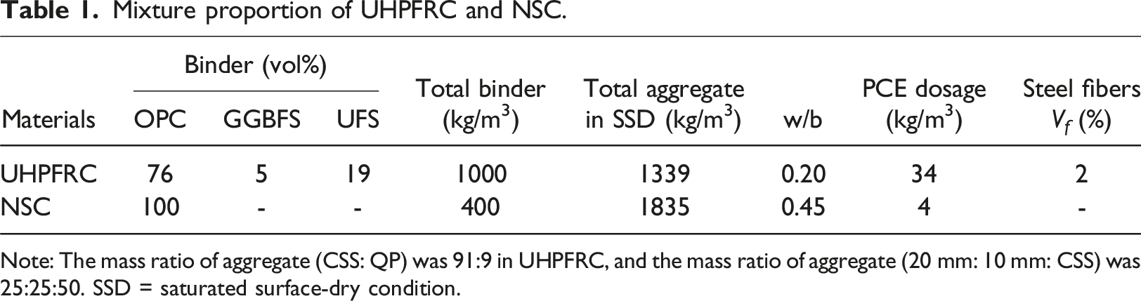
Note: The mass ratio of aggregate (CSS: QP) was 91:9 in UHPFRC, and the mass ratio of aggregate (20 mm: 10 mm: CSS) was 25:25:50. SSD = saturated surface-dry condition.
Mechanical properties of the NSC and UHPFRC mixtures used in present study.
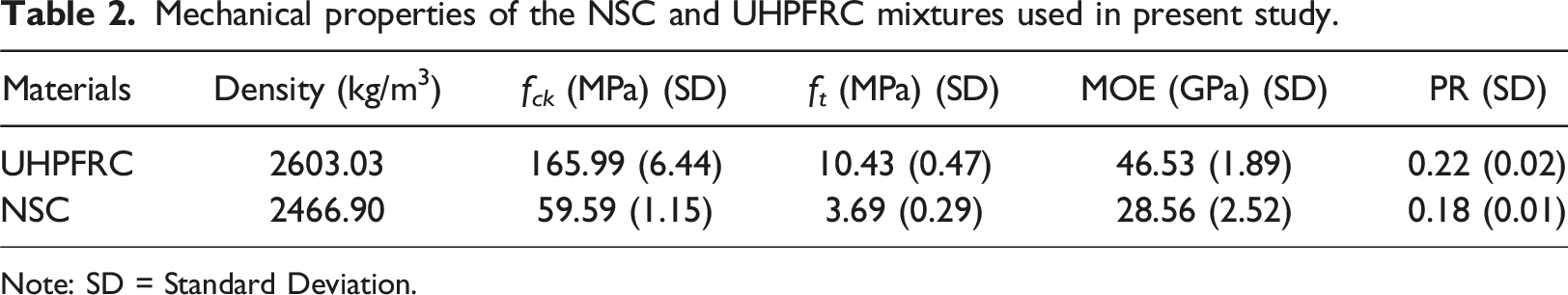
Note: SD = Standard Deviation.
Experimental study
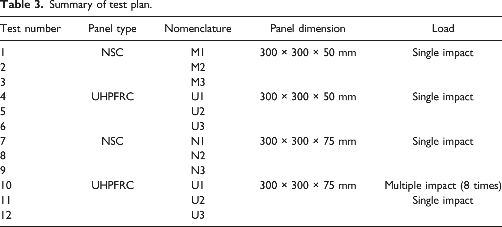
The ballistic resistance of UHPFRC and NSC panels was evaluated by firing 7.62 mm calibre steel-inset bullets from an in-service AK-47 rifle. Twelve 300 × 300 mm panels of 50 mm and 75 mm thicknesses (six each) were cast. Three panels in each thickness were cast from NSC and UHPFRC. The test nomenclature and panels are presented in Figure 1. The experimental test plan is summarized in Table 3. Each panel was subjected to the ballistic impact from 7.62 × 26.62 mm steel-inset ammunition shown in Figure 2, which consists of a brass jacket (3.76 gm), lead cap (1.34 gm), and steel-inset (3.1 gm). Test specimens and nomenclature. Summary of test plan. Dimensional properties of 7.62 × 26.62 mm AK-47 ammunition.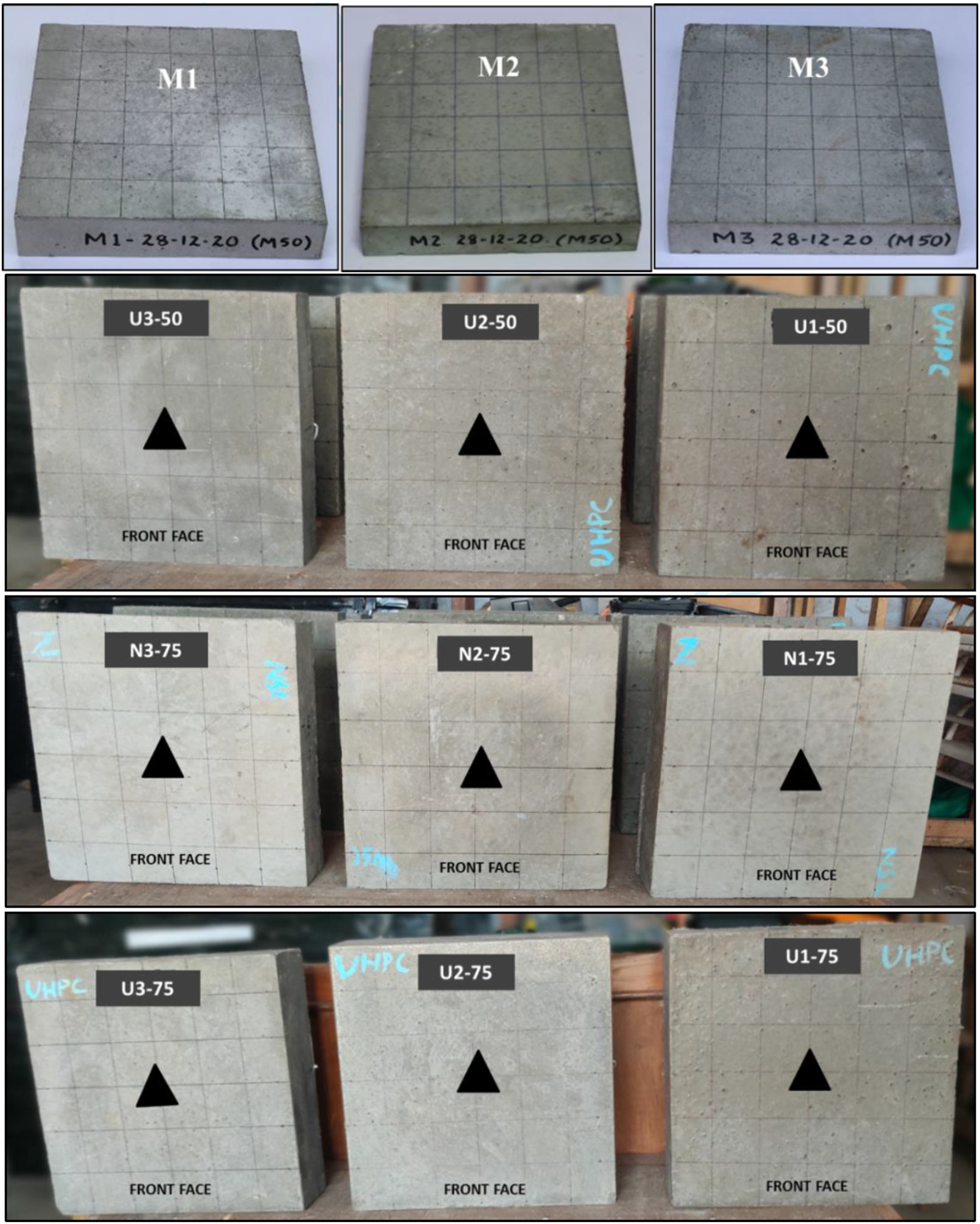
Ballistic test setup
The concrete panels were fixed on an adjustable steel frame (Figure 3(a)). The projectiles were fired from a fixed position to achieve consistent point of impact. A Doppler chronograph was fixed close to the barrel of the weapon to acquire the muzzle velocity. The steel frame with concrete specimen frame was fixed 15 m from the weapon. The impact events were captured using a high-speed camera of 15,000 frames-per-second (fps) frame rate. A white reference screen was provided perpendicular to the high-speed camera to capture the projectiles’ entry and exit. Additionally, a witness sheet was provided to ascertain if the projectile had perforated the test specimen. The illustration of field setup and actual field setup described above, is shown in Figure 3(b) and (c), respectively. Ballistic impact test setup (a) test frame (b) illustration of field setup (c) field setup.
Experimental results and discussion
Summary of experimental results.
Damage profiles of 50-mm NSC panels.
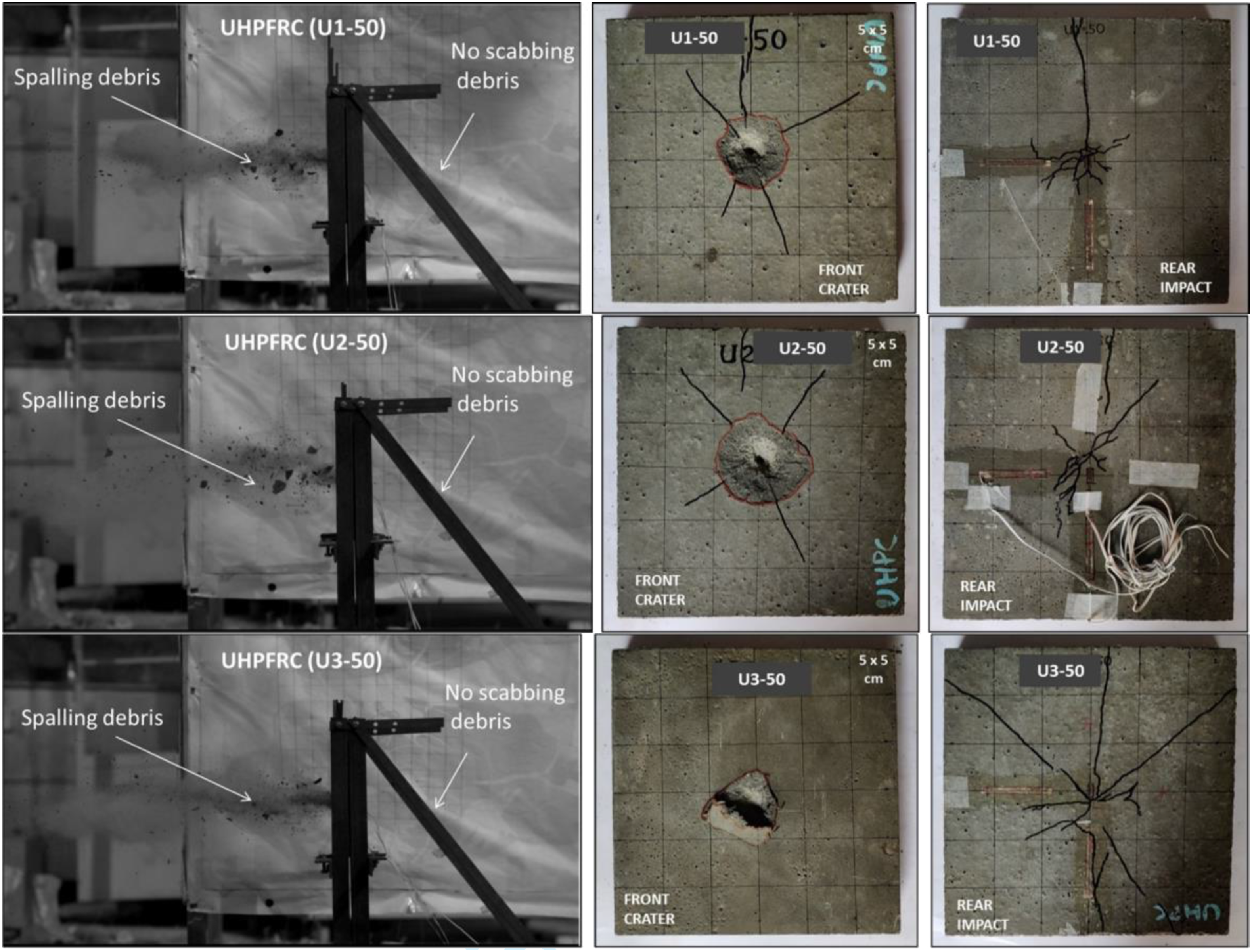
Damage profiles of 50-mm UHPFRC panels.
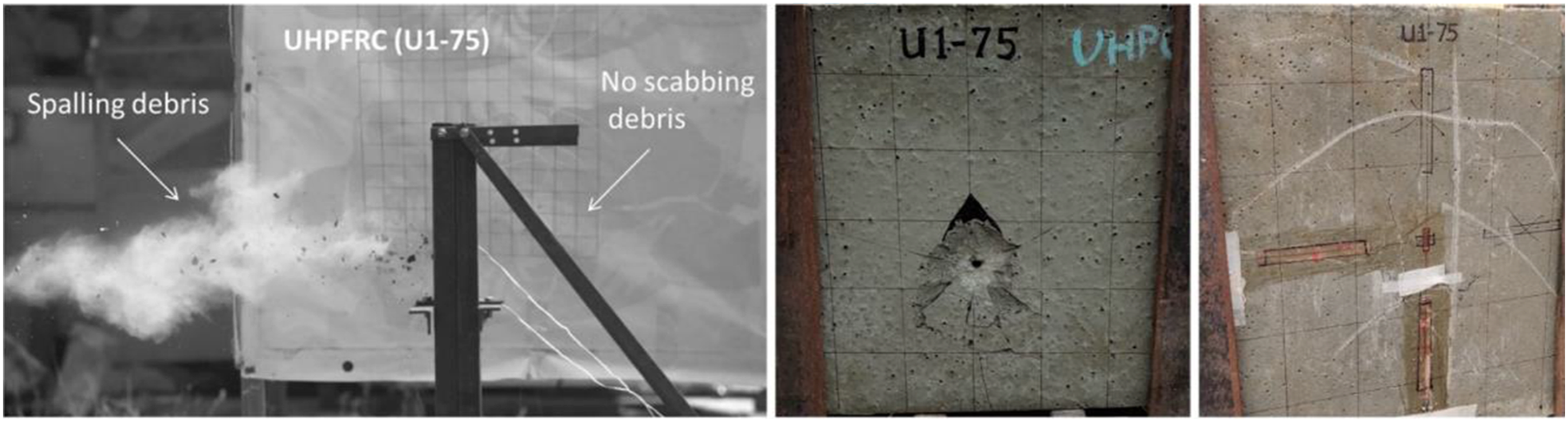
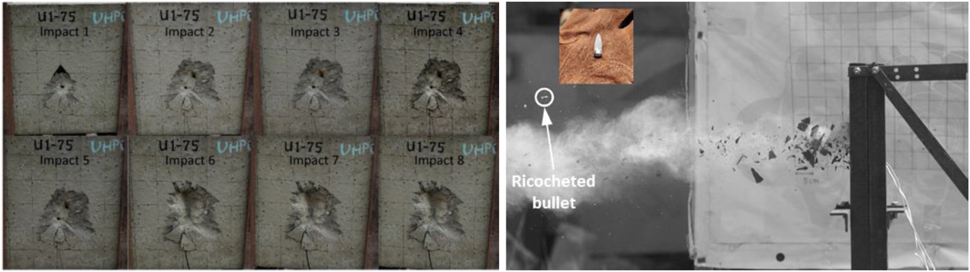
Figures 6 and 7 shows the damage profile of 75 mm thick NSC and UHPFRC panels. These panels were able to stop the bullet within their thickness. It was observed from Figures 6 and 7 that the 75 mm thick NSC and UHPFRC panels showed no distal face scabbing; however, minor cracks were observed in all the panels. It is noteworthy that increasing the thickness of the NSC panels from 50 mm to 75 mm stops the bullet within two-third of its thickness (<50 mm) indicating that perforation limit thickness of the NSC panel is higher than 50 mm. Furthermore, the increase in the thickness of UHPFRC panels from 50 mm to 75 mm led to no further reduction in the DOP (∼29 mm), indicating that perforation limit thickness of the UHPFRC panel is within 50 mm. Hence, 75-mm panels provided sufficient protection against the 7.62 mm calibre steel inset ammunition. This was further ascertained by subjecting a 75-mm UHPFRC panel to multiple impacts. The panel was not perforated after eight impacts, as seen in Figure 8(a); however, a full-depth crack was developed on the sixth impact. Additionally, the steel bullets ricocheted from most of the UHPFRC panels, some intact while others deformed (Figure 8(b)). The steel-inset projectiles decelerated and remained inside most of the 75 mm NSC panels. This may be due to the fact that the UHPFRC panel with much higher strength than NSC panel creates a crumble zone near the bullet lead tip on impacting the panel surface resulting in deviation in the path of steel-inset. Damage profiles of 75-mm NSC panels. Damage profiles of 75-mm UHPFRC panels. (a) Response of 75-mm thick UHPFRC panel to multiple impacts, (b) bullet ricocheted from UHPFRC panel.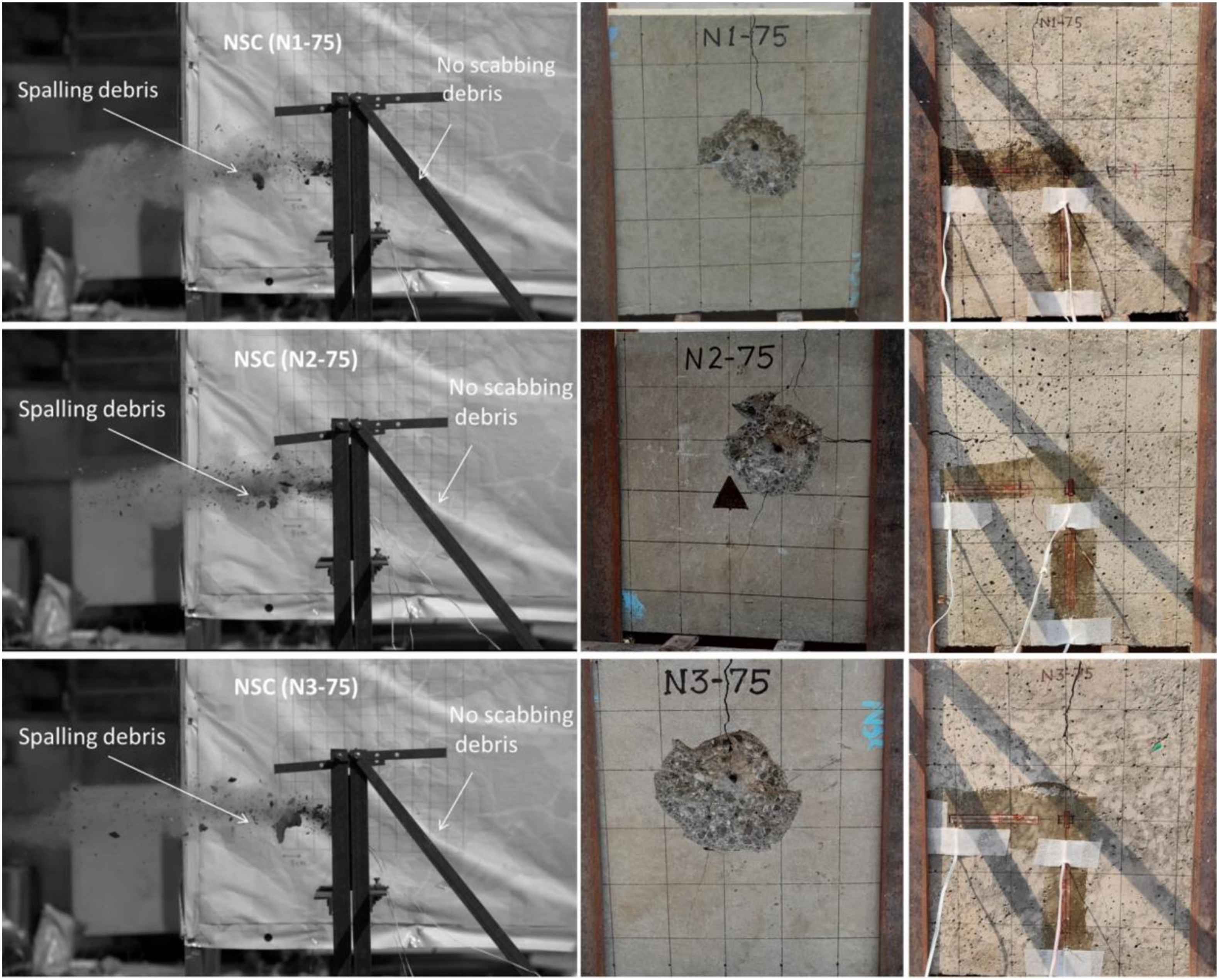
Numerical study
A numerical study was conducted to simulate the impact of steel-inset bullet onto the NSC and the UHPFRC panels using finite element (FE) analysis and to estimate the DOP and the crater diameters of spalling and scabbing. The validated FE model is later used to develop an empirical relationship to predict the DOP of steel-inset projectiles on to concrete slabs of finite thicknesses.
The FE model of the experimental setup was created in LS-DYNA (LSTC, 2017) to validate against experimental results. The details of the FE model, material model parameters for concrete and bullet, mesh sensitivity analysis and the validation of numerical results are presented in the subsequent sections.
Finite element model development
A quarter-symmetric FE model of the experimental setup was created using solid elements with symmetric boundary condition applied across the planes of symmetry. The bullet was modelled using constant stress element, whereas the concrete slab was modelled using fully integrated elements. An adaptive contact available in LS-DYNA (CONTACT_ERODING_NODES_TO_ SURFACE) was used, which allows contact surface to be updated as the elements are deleted from the model. The material models utilized for the concrete panels and the bullet, and their calibrations are discussed in the following sections.
Concrete panel
The Riedel-Hiermaier-Thoma (RHT) model (Borrvall and Riedel (2011)), was employed here to simulate concrete behaviour under high velocity impact. The RHT model features accurate dynamic strength description of concrete for high strain rates and pressures. The RHT material model uses three limit surfaces that is initial yield surface, failure surface and residual surface. The default parameters are available in LS-DYNA for RHT model for concrete of compressive strengths of 35 MPa and 140 MPa, which are intended for concrete without fibres. However, the general behaviour of the UHPFRC differs from the one simulated through the default parameters due to difference in tensile and shear strength as well higher energy absorption capacity. Hence calibration of RHT model for UHPFRC becomes important for accuracy of numerical prediction. The RHT concrete model in current study was calibrated using peak strength and modulus of elasticity mentioned in Table 2 and the profile stress-strain curve reported by Hassan et al. (2012). This approach was adopted due to the similarity in the concrete mix used in both studies. Firstly, a single element analysis (Schwer and Malvar, 2005) with unconfined boundary conditions was conducted in LS-DYNA. As shown in Figure 9, boundary conditions were applied to the element and the top four nodes of the element were given prescribed vertical motion of 0.001 mm/s. The stress-strain behaviour of the solid element was compared with experimental behaviour of UHPFRC in compression and tension to calibrate RHT concrete model. The parameters of RHT concrete model related to residual stress, minimum damaged failure strain, tensile and compressive yield surface were adjusted to obtain required stress-strain behaviour of UHPFRC. A more detailed approach of RHT model calibration for UHPFRC can be found in Naredi (2022). The calibrated RHT concrete model captured the UHPFRC behaviour accurately, including peak tensile and compressive stress, post-peak strain hardening and softening, which can be observed from Figure 9. The RHT model has a single parameter that controls the residual strains in both tension and compression. Hence, a difference between the experimental data and numerical result is observed for post-peak tensile behaviour. Uniaxial behaviour of single cubic element in (a) compression, (b) tension.
The uniaxial stress-strain curve reported by Hassan et al. (2012) is the average stress versus strain obtained from the compression test of cylindrical concrete specimen. Hence, the calibrated RHT concrete model was also validated by obtaining the average stress versus strain curve from the FE model of cylinder. The nodes of cylindrical specimen of were constrained at bottom and free to move at top. The top nodes of cylindrical specimen were applied with 0.5 mm/s to simulate displacement-controlled loading rate. The stress-strain curve obtained from cylinder under compression was compared to stress-strain curve obtained from single element analysis, as shown in Figure 10(a). The good agreement between single element and cylinder shows reliability of the calibrated RHT model. Lastly, the enhancement in concrete strength under triaxial state of stress was verified through the comparison of the stress-strain curves for an element at the cylinder periphery and at the centre of the cylinder in Figure 10(b). Uniaxial stress-strain behaviour of (a) cylinder and single element, (b) elements of cylinder specimen.
RHT model parameters.
Bullet
The bullet used in the experiments had steel-inset, a lead cap and an outer covering of brass jacket. The bullet had a length of 26.65 mm, diameter 7.62 mm and steel-inset weighed 3.1 g with total mass of bullet was 8.2 g. The lead cap and brass jacket erode during initial stages of penetration and the steel-inset is primarily responsible for impact damage to concrete panels. Several studies in the past have only modelled the steel-inset using rigid material (Oucif et al., 2020; Pu et al., 2022; Tremblay et al., 2021; Zhang et al., 2018). This may not be an appropriate assumption in case of ballistic impact to UHPFRC, as was also observed from experiments, in which the steel-inset was damaged and deformed as seen in Figure 11(b). Hence, the bullet was modelled here as a deformable projectile with explicit modelling of steel-inset, lead cap and the brass jacket. The dimension of the bullet and mesh sizes are mentioned in finite element model of bullet is shown in Figure 11(a). (a) Finite element model of bullet, (b) damaged state of bullet.
Material parameters for projectile.
Mesh sensitivity analysis
Mesh sensitivity analysis was performed to understand the influence of mesh size on accuracy of numerical model and depth of penetration (DOP). The quarter-symmetric model of the test setup described in section 4.1 with symmetric boundary conditions was used. Considering that damage induced by high-velocity impact is localized, finer uniform mesh around the central impact area and graded mesh towards the boundaries were adopted (Figure 12(a)). This allowed a better trade-off between the computational cost and the accuracy of the results. A series of analyses were performed with size of mesh in central area varying from 0.25 mm, 0.5 mm, 0.75 mm and 1 mm, and the radial mesh varying proportionally. The result of mesh sensitivity analysis is plotted in Figure 12(b), indicating relation between DOP-mesh size and DOP-number of elements. Based on sensitivity analysis and computational restrictions, a mesh size of 0.25 mm was selected for further analysis. (a) Finite element model of panel (b) mesh convergence study.
Numerical results and discussion
Comparison of numerical results with experimental results.
To assess the internal damage patterns and compare numerical and experimental results, NSC (75 mm) and the UHPFRC panels (50 mm and 75 mm) were cut through using high-pressure water jet cutting technique. During the experiment, NSC panels of thickness 50 mm shattered during the impact tests and could not be recovered for the internal damage assessment through waterjet cutting. The trend of damage in NSC and UHPFRC panels obtained from numerical results is consistent with the experimental observations, as shown in Figure 13. The damage pattern in 50 mm thick UHPFRC panel can be observed from Figure 13(a). The crater depth and bullet penetration for numerical and experimental plots are similar along with the formation shear plug. Figure 13(b) shows the damage pattern in the 75 mm thick UHPFRC panel. Comparable tunnelling depth and crack formation are observed in the numerical and the experimental results. The damage pattern in 75 mm thick NSC panel can be seen in Figure 13(c). The water jet cutting plane of the NSC slab is not along the cross-section plane of peak damage. Hence, fewer cracks were visible in the sample. However, scabbing at rear face of the NSC panel can be clearly seen in the numerical model and the experimental specimen. Comparison of damage pattern in numerical and experimental results.
Development of empirical formula for DOP
Depth of penetration (DOP) is an important parameter to design and assess the safety of concrete target against high velocity impact. DOP depends on several factors, including the material and geometric properties of the projectile and the target, as well as the velocity and angle of impact. Various empirical relationships have been formulated over the past few decades incorporating these considerations to estimate the depth of penetration. These relationships have been developed using the rigid penetrator assumption and for concrete up to limited compressive strength (e.g., Murthy et al. (2010); Xue et al. (2017)). These assumptions are not suited for deformable projectile impact to UHPFRC panels, as observed in the current study. Hence, a numerical parametric study was conducted here to develop an empirical relationship to predict DOP of concrete slabs against steel-inset ammunitions of similar calibre. This would especially be useful for the design and construction of protective structures, where such ammunitions are of primary threat.
Prediction using existing formulae
Numerous empirical formulae were developed and modified over the years to estimate depth of penetration of projectile in concrete target (ACE, 1946; Amirikian, 1950; Bangash, 1989; Barr, 1988; Chelapati et al., 1972; Coleman, 1946; Gwaltney, 1968; Haldar and Hamieh, 1984; Hughes, 1984; Kar, 1978; Kennedy, 1976; Li et al., 2005; NDRC, 1946; Samuely and Hamann, 1939; Teland, 1998; Wen and Yang, 2014; Whiffen, 1943). These formulae were developed to estimate DOP for specific impact scenarios and have several limitations. For example, most formulae assume rigid projectile impacting a NSC target of infinite depth. Hence, these may not be universally applied to all types of projectiles and concrete targets. The DOPs were estimated using existing empirical formulae for the 300 × 300 × 75 mm NSC (59 MPa) and UHPFRC (166 MPa) targets subjected to high velocity impact from bullet striking at the velocity of 660 m/s, and the values are presented in Figure 14. A significant variation is observed among the DOPs predicted by relationships proposed in the literature. Thus, there is a necessity to investigate and develop an empirical relationship to estimate the DOP, which is suited for the impact scenarios similar to current study. A dimensional analysis was performed to develop the empirical relation for DOP and presented in the following section. Prediction of DOP using empirical formulae.
Depth of penetration using dimensional analysis
Parameters considered for dimensional analysis.
The projectile impact problem involves three dimensions, namely, mass (M), length (L) and time (T) and two load parameters and three resistance (five physical variables). Hence there are only two non-dimensional terms (
The DOP normalized against slab thickness is estimated using the relationship in equation (2). Linear regression fitted function for DOP.
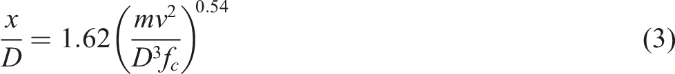
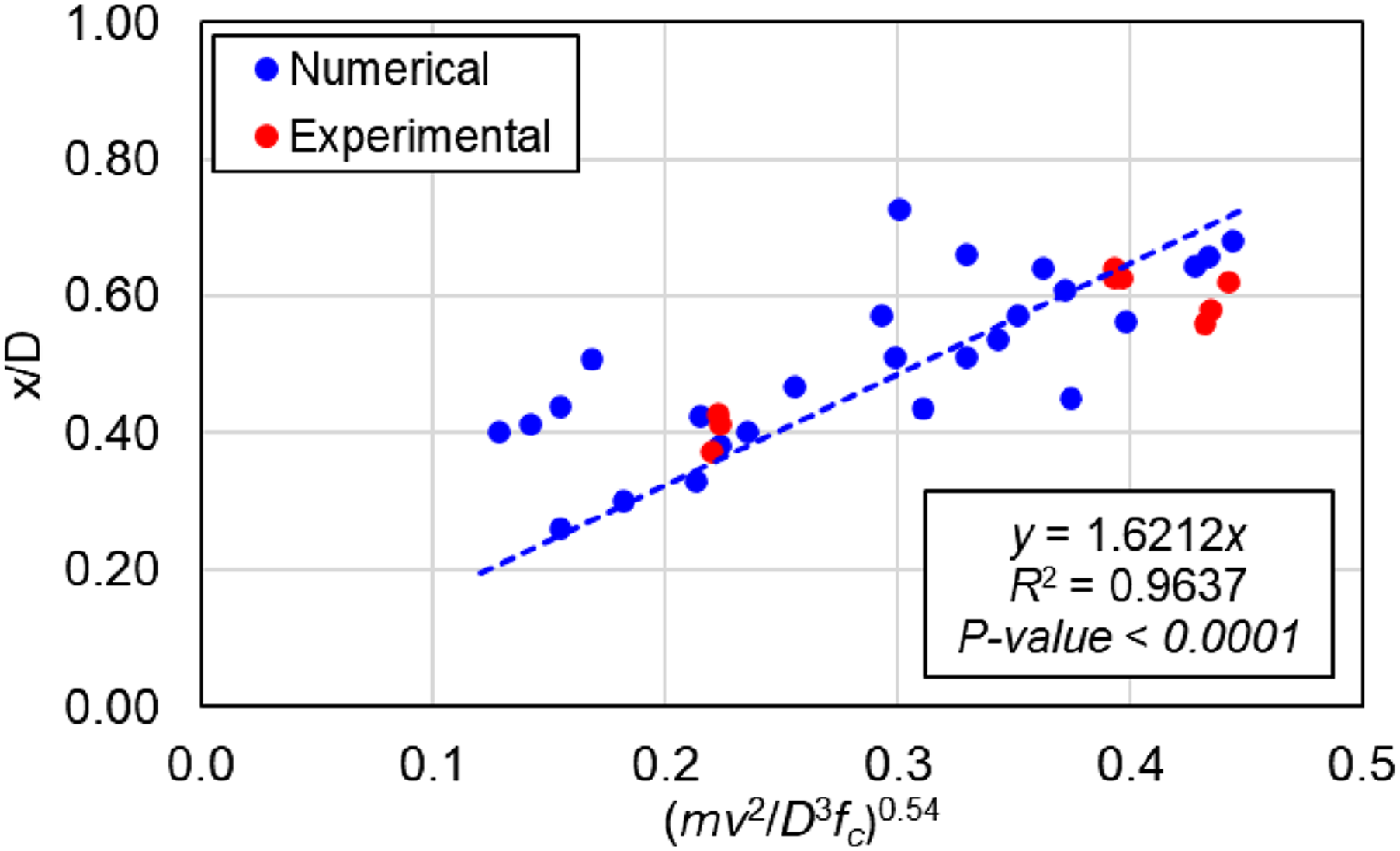
This equation allows the estimation of the DOP in concrete slabs with compressive strength ranging from 75 to 190 MPa and thicknesses ranging from 50 to 100 mm, subjected to high velocity impact between 450 and 1300 m/s from deformable projectiles with mass ranging from 5 to 18 g and characteristics similar to the steel-inset ammunition used in the current study. The R-squared value reported in Figure 15 indicates strong correlation between x/D and (mv2/D3f c )0.54. The developed empirical formula does not explicitly consider the influence of the fibres (e.g. size, volume) on the depth of penetration. However, the calibrated RHT material model used in numerical simulations – over a range of compressive and tensile strengths – allows a wider application of this model to NSC and UHPFRC targets.
Conclusions
This paper presents experimental and numerical studies performed to investigate the response of normal strength concrete (NSC) slabs and ultra-high performance fibre reinforced concrete (UHPFRC) slabs subjected to projectile impact (7.62 mm calibre steel inset ammunition) from conventional weapons. The study showed that the UHPFRC improves impact resistance in terms of the DOP, scabbing and spalling crater diameter compared to NSC. The increased resistance is due to higher superior tensile and compressive properties of UHPFRC combined with higher toughness. The DOP in a UHPFRC panel was 36% smaller than the NSC panels with the same type of projectile and boundary conditions. The perforation limit thickness for the NSC and the UHPFRC panels were close to 75 mm and 50 mm, respectively. In other words, a significantly lower thickness of UHPFRC will be needed to provide the same level of protection against a same projectile impact compared to NSC. Additionally, there was no damage in terms of secondary fragmentation in the UHPFRC panels. A great advantage of UHPFRC could be observed against repeated impact where the 75 mm UHPFRC panel was able to withstand multiple (8 times) impacts before substantial damage. This has a major implication for protective structures in active combat scenarios, which are vulnerable to such threats.
This paper also presents an experimentally validated numerical model developed in LS-DYNA. The recommended modelling parameters for concrete and the bullet were provided through calibration with experimental data and sensitivity analysis. The validated model was used to perform numerical analyses with different parameters. The experimental and numerical results were used in Buckingham’s theorem to develop an empirical equation. The equation can be used to predict the depth of penetration for different combinations of load (projectile properties: mass 5-18 gm, velocity 450-1300 m/s) and resistance (concrete properties: compressive strength 75 -190 MPa) parameters within the NSC and UHPFRC range considered.
Footnotes
Declaration of conflicting interests
The author(s) declared no potential conflicts of interest with respect to the research, authorship, and/or publication of this article.
Funding
The author(s) disclosed receipt of the following financial support for the research, authorship, and/or publication of this article: This work was supported by the Armament Research Board (ARMREB) of Defence Research and Development Organisation (DRDO) (ARMREB/STE/2020/228).