
Abstract
Although the mobility of climbing robots has made significant progress, especially the flipping climbing robots which possess strong adaptability to unstructured environments, their movement in complex unstructured constrained environments remains a challenge. This work proposes a flipping continuous wall-climbing robot, which maintains the capabilities of wall climbing, turning, obstacle overcoming, and transitioning between different planes. It can continuously move across unstructured wall surfaces, traverse narrow gaps, and crawl on walls in constrained spaces. The robot is composed of a trunk formed by three segments of continuous joint groups and magnetic adhesion modules at both ends, utilizing an untethered design. We conducted an analysis of the robot’s kinematic model and workspace. Experimental results demonstrate that the robot is equipped with multiple basic locomotion abilities, allowing it to execute 360° transitions between surfaces, navigate through apertures measuring 15 cm in diameter (0.37 body length), and move along the side walls of confined spaces that are 11 cm wide (0.27 body length). Additionally, the robot is capable of variable-radius flipping locomotion, supporting an effective payload of 520 g on the wall surface, and facilitating coordinated movement among multiple robots.
Keywords
Introduction
The demand for robots is increasing due to human society and industry development, and robotic technology continues evolving and finding applications in different fields. As an essential branch of special robots, climbing robots can replace humans in performing tasks in high-altitude and dangerous environments.1,2 As a type of climbing robot, wall-climbing robots are widely used in vertical surface operation scenarios of artificial structures, such as buildings, storage tanks, and industrial equipment. 3 With the continuous expansion in scale and increasing number of buildings and industrial facilities, the demand for wall-climbing robots in practical engineering applications has been steadily rising, and their research has emerged as a key focus within the field of climbing robot research.
Nevertheless, facilitating the movement and operation of wall-climbing robots in complex, unstructured, and confined spaces still poses a substantial challenge. For example, when it comes to inspecting and maintaining steel structure bridges, shield machines, and iron towers, these structures feature large volumes and significant heights. Furthermore, the operation and maintenance activities sometimes must be conducted at high altitudes or in confined spaces.4,5 In addition, the surfaces of steel structures present various obstacles, gaps, stiffeners, weld seams, and interleaved multiple planes, requiring the robot to possess flexible mobility, obstacle-crossing ability, and the capability to switch between multiple planes.6,7
Currently, the research on wall-climbing robots is categorized into two types based on material and structural differences: rigid and soft wall-climbing robots.8–25 Most rigid wall-climbing robots comprise rigid brakes, transmission elements, and linkages, leading to an excessively large overall volume and a complicated structural design.8–13 Moreover, most rigid wall-climbing robots have relatively limited mobility functions, making it impossible to simultaneously perform wall-climbing, turning, obstacle overcoming, and surface-to-surface transition movement.14–16 However, some robots possess strong mobility capabilities, which provide directions and objectives for improving the locomotive performance of wall-climbing robots.17–20 Lee et al. 19 proposed a climbing robot that utilizes an adhesive suction module to traverse thin-walled surfaces. Hong et al. 20 proposed a quadrupedal climbing robot capable of agile movement on steel surfaces and transitioning between floors, walls, and ceilings.
Compared with rigid wall-climbing robots, soft wall-climbing robots possess flexible mobility and adaptability to unstructured working environments due to the softness of their constituent materials.21,22 Gu et al. 23 presented a soft wall-climbing robot that incorporates various modes of movement and proposed a control strategy to ensure stable climbing performance. Kanada et al. 24 designed a LEeCH robot, which has few shape constraints and can move across thin sheets. Park et al. 25 proposed a soft wall-climbing robot. The trunk of this robot can achieve flexible bending and stretching, and can also undergo complex deformations, thus adapting to various working environments.
From the robots listed above, it can be observed that researchers are concentrating on how to enable wall-climbing robots to possess multiple basic motion capabilities (wall-climbing, turning, and overcoming obstacle) while enhancing their motion capabilities between transition planes and their adaptability to unstructured working environments. In addition, a lightweight trunk structure, simple control strategies, and a wireless design can allow wall-climbing robots to better adapt to complex and unstructured working environments.26–33 The introduction of the flipping locomotion presents a viable option for fulfilling the demands mentioned above. Guan et al. 31 proposed a negative pressure adhesive wall-climbing robot with multiple modes of locomotion, with the flipping gait enabling the robot to overcome obstacles better. In addition, the robot can also perform operational tasks (our robot is also inspired by this design). Malley et al. 32 developed a small flipping bipedal wall-climbing robot that can autonomously navigate between vertical surfaces and transitional planes without complex sensors and control systems, achieving an untethered design. Chen et al. 33 developed a flipping wall-climbing robot with multiple locomotion capabilities, including wall-climbing, turning, and transitioning between different planes, weighing only 2.75 g.
Although existing flipping wall-climbing robots already possess capabilities such as wall-climbing, turning, and transitioning between different planes,31–33 the flipping gait still faces the following challenges when confronted with complex unstructured environments. First, the flipping gait requires a larger movement space that must be free of obstacles, which challenges the robot’s mobility in complex environments. Second, the existing flipping wall-climbing robots cannot achieve large-angle transitions between different planes, which hinders the robot’s adaptability to unstructured working environments. Third, existing flipping-type wall-climbing robots have a fixed flipping stride, which prevents the robot from directly reaching a designated area or target point, thereby indirectly affecting the robot’s traversability. Finally, enabling flipping wall-climbing robots to simultaneously possess wall-climbing, steering, obstacle crossing, and plane-to-plane transition capabilities while achieving an untethered design remains a significant challenge.
To address the challenges above, we propose a flipping continuous wall-climbing robot. This robot employs a continuous structure as its torso, enabling it to possess multiple fundamental locomotion capabilities and navigate complex, unstructured, constrained environments while achieving a wireless design. Furthermore, the robot’s torso comprises multiple segments of serially connected continuous joint groups and a distributed layout strategy for driving flexible cables. This approach addresses the issues of fixed stride length and excessive motion space during the flip walking of the wall-climbing robot, further enhancing its adaptability in unstructured environments. Finally, implementing coordinated movement among multiple robots significantly enhances the robotic system’s overall mobility and operational capabilities.
Methods
Design of the continuum wall-climbing robot
The locomotion patterns of small insects in nature, such as inchworms and caterpillars, inspire the flipping gait.34,35 During movement, one robot’s end adheres to the ground while the other end flips within the workspace. Therefore, the performance of the torso directly determines the locomotion capabilities of the flipping gait robot. Inspired by the high flexibility of elephant trunk movement and its strong adaptability to complex environments, we adopted a continuous structure as the torso of the wall-climbing robot. We designed a continuous wall-climbing robot with a flipping gait (Fig. 1).
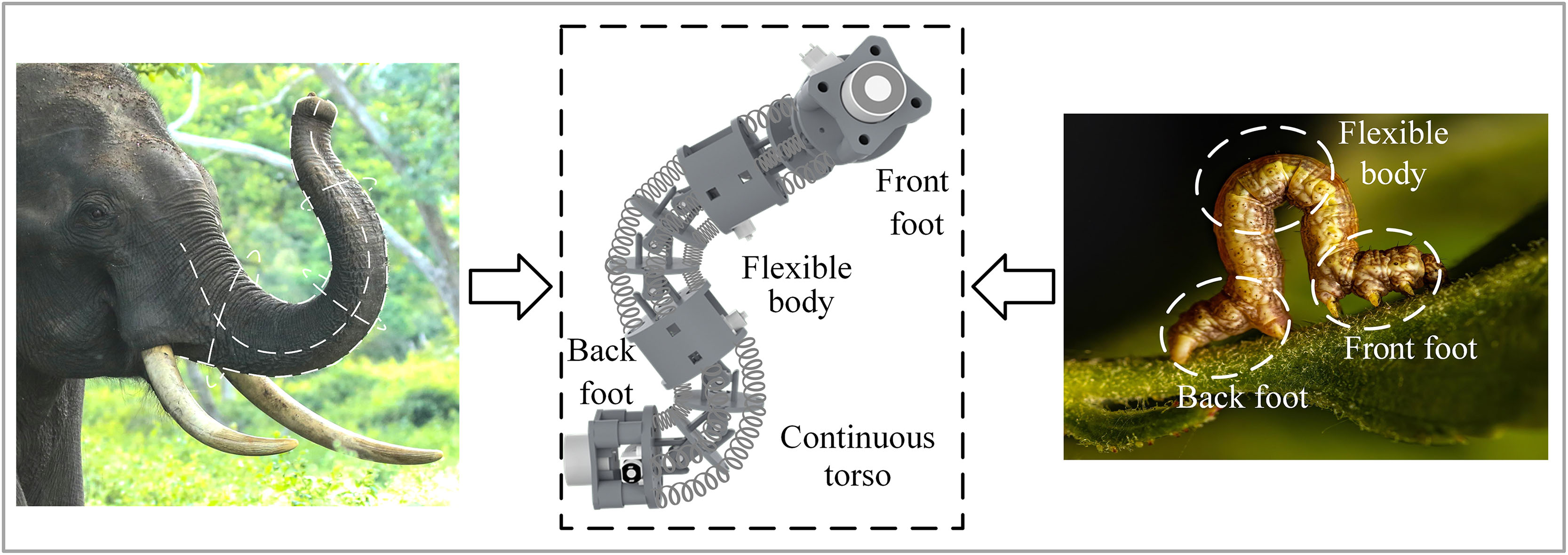
The structural design inspiration of the robot comes from the structural characteristics of the inchworm and the flexibility of the elephant’s trunk movement.
Continuous torso
In designing the torso structure for continuous wall-climbing robots, the connection method between adjacent joint modules and the large-angle curvature of the torso are two critical factors. Furthermore, selecting lightweight and compact drive motors and a rational structural design is essential to ensure that the robot’s center of gravity aligns vertically with the multiple serial joint modules, guaranteeing the stability of the robot’s flipping locomotion gait.
Currently, the common types of connecting joints in continuous robots are primarily spherical and universal joints. To ensure the flexibility and stability of the robot during the flipping motion, we conducted a comparative analysis of these two types of connection methods. Based on the analysis of prototype testing, the universal joint configuration generates lower friction with the joint modules compared with the spherical joint configuration, thereby requiring less tension from the drive tendons. Additionally, the universal joint configuration ensures the axial positioning of the continuous torso and facilitates a balanced distribution of the center of mass within the torso structure. Therefore, the universal joint configuration is selected as the connection scheme between adjacent joint modules in the torso.
In addition, during the experimental process, we observed that as the number of series-connected joint modules increases, the friction between the actuating cables and the joint modules accumulates when the torso undergoes large-angle bending deformations, increasing the load on the driving motor. Meanwhile, within the driving circuit of the continuous joint assembly, friction causes the actuating cables closer to the driving motor to contract more rapidly than those further away, resulting in nonuniform contraction between adjacent joint modules in the torso. Consequently, this leads to discrepancies between the actual bending deformation trajectory of the torso and the trajectory predicted by theoretical analysis. 36
Based on the analysis above, we employed the strategies of reducing the number of joint modules and shortening the length of the actuating cables to mitigate the adverse effects of friction and to control the bending shape of the torso.
Ultimately, the implementation of a multi-segment joint group series structure in conjunction with a distributed actuation strategy for the flexible cables enables large-angle bending of the robot’s torso. The overall structure of the robot is shown in Figure 2a. The entire robotic torso consists of three segmented joint groups arranged in series, with adjacent joint groups interconnected through connection modules and adsorption modules mounted at both ends of the torso. Each joint segment assembly consists of two joint modules arranged in series, with adjacent joint modules interconnected by a cross-axis universal joint, connecting springs, and driven compliant cables (Fig. 2d). The connecting spring primarily transmits the driving force generated by the motor, thereby enabling adjacent joint modules to achieve identical bending angles. Meanwhile, the self-weight of the joint and connection modules causes the continuous trunk to bend under a cantilevered configuration, and the connection spring serves to counteract this gravitational force (for the specific analysis content, Supplementary Data S1). The maximum bending angle of adjacent joint modules is 43°, while the maximum bending angle of a single-segment joint group is 129°, and the entire continuous trunk is capable of achieving a bending angle of 387°.
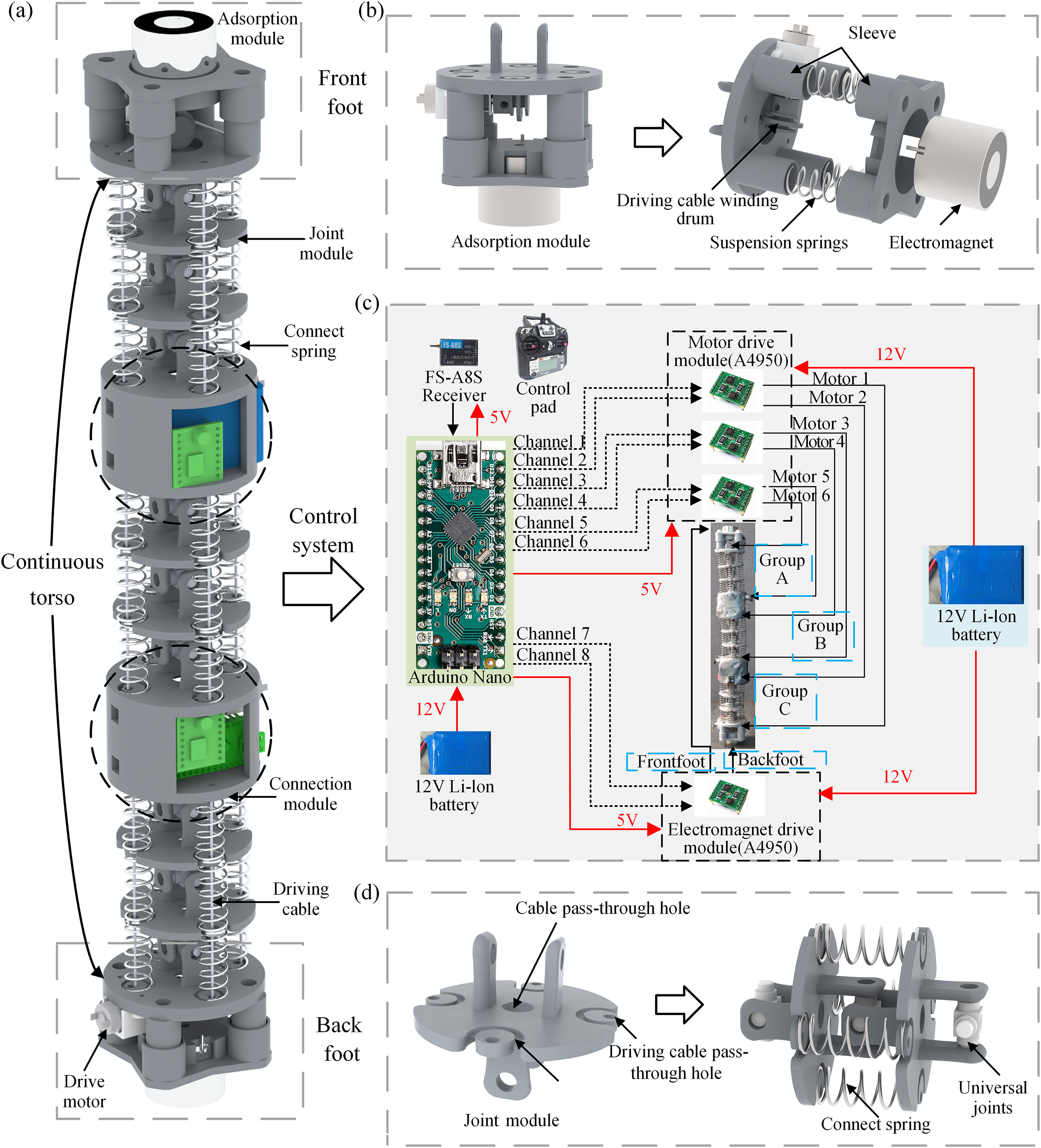
Schematic of the overall structure and control system of the flipping continuous wall-climbing robot.
The connecting module can be utilized to link two adjacent joint assemblies and extend the length of the robot’s torso, facilitating the proper functioning of the adsorption module on the working surface during substantial torso bending. In addition, the connecting module can be used to accommodate the installation of drive motors, batteries, control modules, and other components, thereby providing installation space for the wireless design of the robot.
Adsorption module
The adhesion issue is one of the critical challenges for wall-climbing robots in achieving effective wall-climbing motion. Various adhesion methods have been developed for wall-climbing robots, including permanent magnet adhesion, 4 electromagnet adhesion,16,21 wet and dry adhesion, 10 pin, hook, and micro-pin adhesion, 9 as well as negative pressure adhesion.23,30 However, considering the requirements for substantial suction force and a wireless design, we selected an electromagnetic adhesion. It has the following advantages: First, the adsorption and detachment of the electromagnet can be rapidly achieved by controlling the on-off state of the current, presenting a straightforward control strategy. Second, the electromagnet is characterized by its compact size and high magnetic force. Moreover, the two electromagnets enable rapid attachment and detachment, facilitating the quick formation of coordinated movement among multiple wall-climbing robots. The final selection was a solenoid with a rated voltage of 12 V and a holding force of 15 kg (KK-P30/25, Kaka Electric Co., Ltd., China).
The adsorption module primarily consists of an electromagnet, a mounting frame, and four suspension springs (Fig. 2b). The structural dimensions of the adhesion modules at both ends of the torso are identical. In addition, the suspension springs are utilized to buffer the vibrations caused by the sudden attachment of the electromagnet to the wall as the distance between the electromagnet and the wall decreases. The suspension springs are installed in the corresponding sleeves, which primarily prevent excessive deformation of the springs due to gravitational forces when the robot’s torso is in a cantilevered position, thereby preventing spring failure.
Control system of the robot
When the wall-climbing robot operates in complex confined spaces, the dragged cables may become entangled with surrounding structures or obstacles, increasing the robot’s load and restricting its range of motion. Therefore, we have implemented a wireless design for the robot to facilitate its movement in complex and unstructured confined spaces. Currently, the robot operates in an open-loop control state, with its control system illustrated in Figure 2c. An Arduino Nano was used as the microprocessor, an FS-A8S was employed as the control signal receiving module, and an A4950 was utilized as the motor and electromagnetic drive module. Two 12 V 400 mAh lithium batteries power the microprocessor, motor drive module, and electromagnetic drive module. A 5 V supply from the microprocessor powers the control signal-receiving module. The working process of the robot is as follows: First, the control signal is sent by the remote controller (FS-i6x) and received by the signal receiving module, which then transmits the control signal to the Arduino Nano. Subsequently, the Arduino sends the control signals to the motor driver module. Finally, the motor driver module controls the motor’s forward and reverse rotation. The operating process of the electromagnet is similar to that of the motor. Although the robot is currently operating in an open-loop control state, future work will enhance its ability to perceive the surrounding environment and provide feedback on critical information during movement, ultimately achieving autonomous flipping for the robot.
Flipping walking radius analysis
Although the flipping walking gait can significantly improve the surface-to-surface transition capability and obstacle-crossing performance of wall-climbing robots, when robots encounter continuous obstacles or operate in unstructured environments, a fixed walking turning radius may constrain their locomotion performance and environmental adaptability. Therefore, the implementation of variable-radius flipping walking is crucial for improving the adaptability of wall-climbing robots in unstructured environments.
The robot’s torso is composed of three independently driven continuous joint groups arranged in series. By controlling the bending angles of these joint groups, the displacement in the flipping direction can be precisely regulated, thereby enabling the implementation of a variable-radius flip walking strategy. Therefore, by establishing a geometric model of the bending angles of the three-segment joint group within the robot’s torso, the theoretical expression for the flipping walking radius and its corresponding range of values can be derived. As shown in Figure 3, when the robot performs a variable-radius flip walk on a plane or wall surface, the electromagnets at both ends of the torso must ultimately be parallel to and in contact with the adhesion surface to ensure stable attachment. At this stage, the geometric center arcs of the first and third joint groups must exhibit symmetry with respect to the torso’s central axis. Based on this analysis, it can be logically inferred that the bending angles of both first and third joint groups are equal. According to this analysis, to achieve a variable-radius flipping walking strategy, bending angles of the three-segment joint group must satisfy fundamental constraint conditions specified in Equation (1).
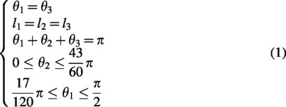
In Equation (1), l1, l2, and l3 denote the circular arcs generated by the geometric centers of the corresponding joint groups in the robot’s torso following bending deformation. Since the geometric length of the robot’s torso remains unchanged during its movement, the length of the curved arc formed by the geometric centers of each joint group also does not change. Based on the initial length of the robot’s torso, l1 = l2 = l3 = 81 mm. θ1, θ2, and θ3 denote the arc angles formed by the respective corresponding joint groups.
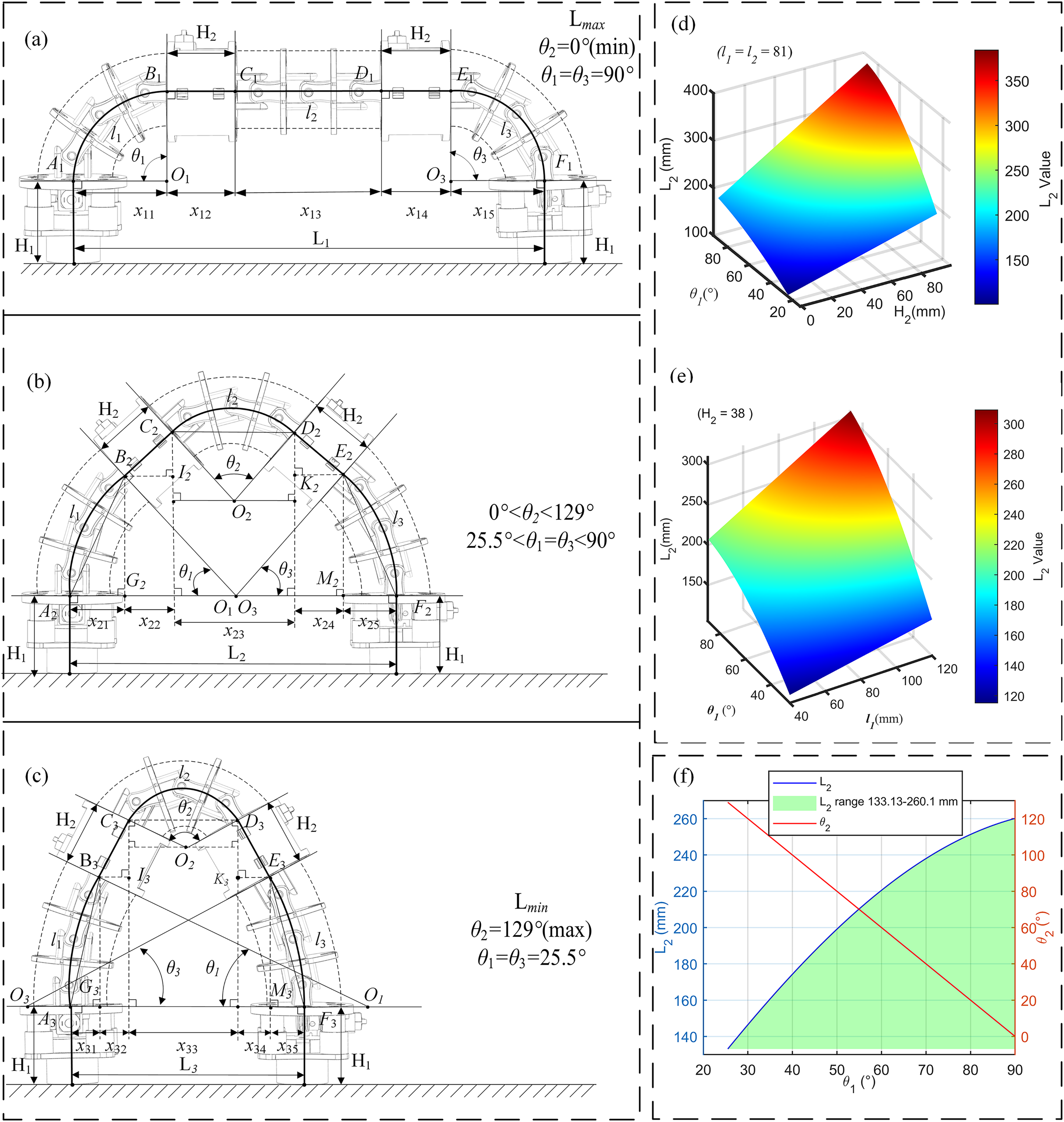
After satisfying the basic constraint conditions for the robot’s flipping walking, geometric analysis of Figure 3 reveals that a smaller bending angle of the second joint group results in a greater horizontal displacement of the robot’s torso, while a larger bending angle leads to a smaller horizontal displacement. When the bending angle of the second segment joint group is 0°, the horizontal displacement of the torso reaches its maximum value; when the bending angle is 129°, this displacement reaches its minimum value. Therefore, by further constraining the values of θ1, θ2, and θ3, the variation range of the robot’s walking radius during the flipping motion can be determined.
Figure 3a presents a schematic diagram illustrating the geometric analysis of the robot’s maximum flipping walking radius. When θ2 = 0°, θ1 = θ3 = 90°, the horizontal projections of the arc lengths l1 and l3 of the first and third joint groups are, respectively, x11 and x15. The arc length l2 of the second joint group and the horizontal projections of the length H2 of the connecting module are, respectively, x13, x12, and x14. At this point, the robot’s flipping walking radius can be expressed as L1. In Figure 3a, geometric analysis reveals that:
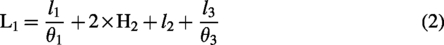
Substituting l1 = l2 = l3 = 81 mm, θ1 = θ3 = 90°, and H2 = 38 mm into Equation (2), the value of L1 can be calculated as 260.18 mm.
Figure 3b presents a geometric analysis diagram illustrating the robot’s arbitrary flipping walking radius. In this scenario, θ2 ranges from 0° to 129°, and θ1 = θ3 ≠ 90°. The horizontal projections of the arc lengths l1 and l3 of the first and third joint groups are denoted as x21 and x25, respectively. Based on the cosine theorem and geometric analysis, it can be derived that
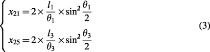
The arc length l2 of the second joint group and the horizontal projection of the length H2 of the connecting module are, respectively, x23, x22, and x24. Based on trigonometric principles and geometric analysis, it can be derived that

At this stage, the robot’s flipping walking radius can be mathematically expressed as L2.
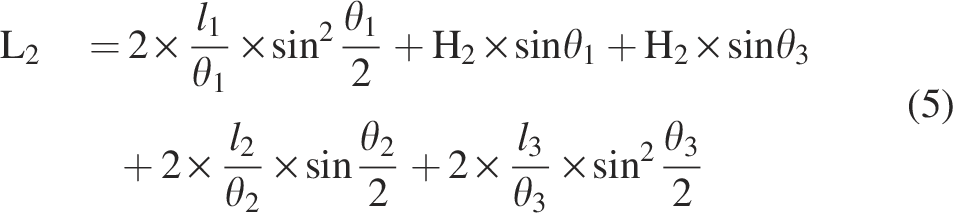
Furthermore, substituting θ1 + θ2 + θ3 = π and θ1 = θ3 into Equation (5), it can be further simplified as
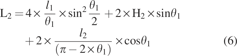
At this moment the range of θ1 is (25.5°, 90°), and Equation (6) does not attain a maximum or minimum value, but it has a definite bound. When θ1 approaches 90°, the upper bound of L2 is 260.13, and when θ1 approaches 25.5°, the lower bound is 133.31 mm. Therefore, the range of L2 is (133.13, 260.13).
Figure 3c presents a geometric analysis of the minimum walking radius during the robot’s flipping motion. When θ2 = 129° and θ1 = θ3 = 25.5°, the horizontal projections of the arc lengths l1 and l3 for the first and third joint groups are denoted as x31 and x35, respectively. Based on the cosine theorem and geometric analysis, it can be derived that
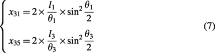
The horizontal projections of the arc length l2 of the second joint group and the length H2 of the connecting module are denoted as x33, x32, and x34, respectively. It can be known through trigonometry and geometric analysis that
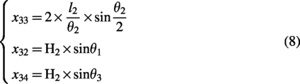
At this moment the minimum walking radius during the robot’s flipping motion can be mathematically represented as L3.
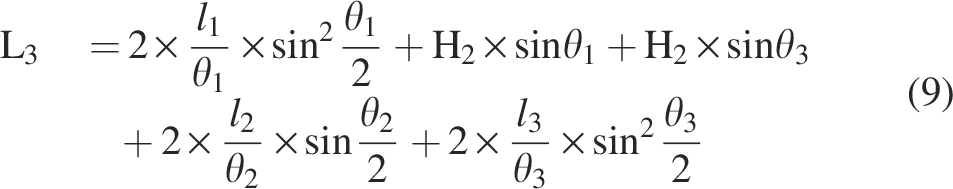
By substituting the parameters l1 = l2 = l3 = 81 mm, θ1 = θ3 = 25.5°, θ2 = 129°, and H2 = 38 mm into Equation (9), the value of L3 can be calculated as 133.13 mm.
From the above analysis, it can be concluded that Equation (6) is the expression of the robot’s flipping walking radius. By adjusting the length H2 of the connection module and the initial values of the lengths l1 and l2 of the bending arc of the geometric center of the joint group, the range of values for the robot’s flip walking radius can be changed. As shown in Figure 3d, when the arc lengths l1 and l2 at the geometric center of the joint group are both set to 81 mm, the relationship between the robot’s flipping locomotion radius L2 and the parameters H2 and θ1 can be visualized using a three-dimensional surface plot. Figure 3e demonstrates that as the value of H2 increases gradually, the variation in L2 becomes more pronounced. Furthermore, using Equation (6), the corresponding θ1, θ2, and θ3 can be numerically solved when the parameter values (L2) are provided, enabling control of the robot’s flipping walking radius, as illustrated in Figure 3f. Based on the above analysis, the geometric model of the bending angles of the three-segment joint group in the robot’s trunk was established, from which the theoretical range and expression of the flipping walking radius were derived in Equation (6). This provides a theoretical foundation and control basis for the subsequent design and motion performance testing of the robot’s flipping walking radius.
Kinematic analysis
The robot’s torso is composed of multiple serially connected joint segments, where each joint segment’s motion space influences the robot’s overall motion space. Therefore, we first analyze the kinematic model of the single joint segment of the robot, followed by an analysis of the kinematic model of the multi-segment joint configuration. 36 In the analysis, it is assumed that the joint modules in each segment of the joint group have the same bending angle and that the bending curve is smooth and continuous. The analysis of the robot’s kinematics is based on the piecewise constant curvature assumption and the Denavit–Hartenberg method. Furthermore, the kinematic model analysis of the robot focuses on establishing the geometric relationship between the variation in driving flexible cable length and the bending and deflection angles of the joint group. This analysis does not involve any velocity-related physical quantities.
The joint space and operational space of the single-segment joint group
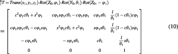
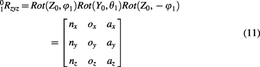
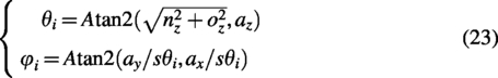
To describe the bending deformation of a single-segment joint group, a base coordinate system (O0-X0Y0Z0) and an end coordinate system (O1-X1Y1Z1) have been established (Fig. 4a). Additionally, to establish the kinematic model of the single-segment joint group, its bending angle is defined as θ1 and the deflection angle as φ1, with their respective value ranges being [0, 129°] and [0, 360°]. The transformation from the base coordinate system O0-X0Y0Z0 to the end effector coordinate system O1-X1Y1Z1 can be achieved through one translation and three rotations. Based on the spatial geometric relationship and the D-H convention for robots, the homogeneous transformation matrix between the two systems can be expressed as:
Kinematic analysis of a single-segment joint group.
In Equation (10), Trans() and Rot() denote the translation and rotation functions, respectively, and c and s represent the cos and sin.
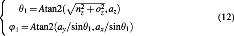
It can be further derived that the inverse kinematics mapping relationship between the joint space and the operational space in a single-segment joint group is given by:
The drive space and joint space of the single-segment joint group
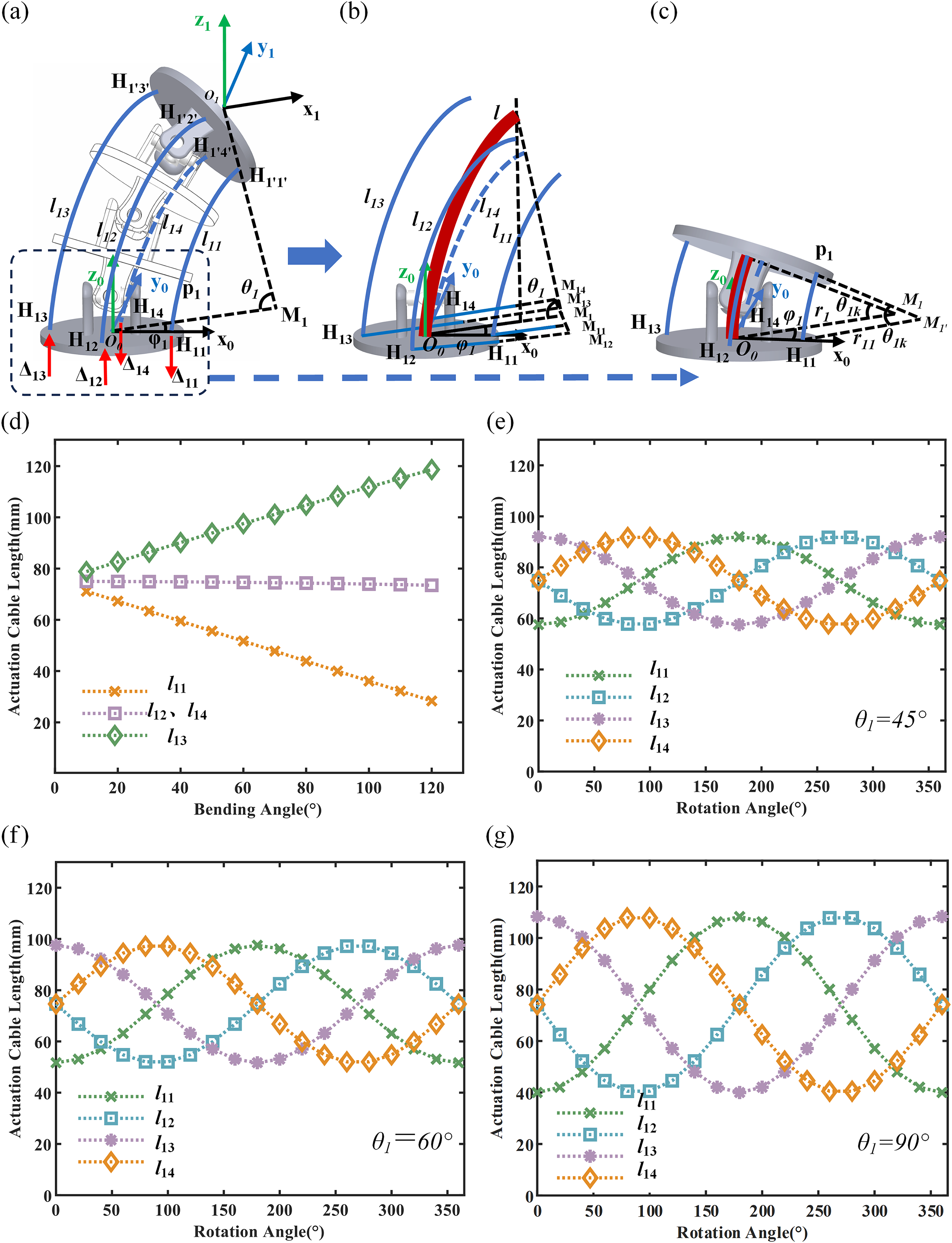
A geometric model analysis is conducted to establish the mapping relationship between the variation in the drive cable length and the bending and deflection angles of the single-segment joint group (Fig. 4b). The drive cables between the two joint modules are distributed along a circular arc with a radius of ra, with an angular difference of 90° between them. Due to the bending and deflection of the single-segment joint group, the projection of the driving flexible cable on the X0O0Y0 plane remains parallel to the projection of the central axis of the joint group. Furthermore, the center of the arc of the flexible cable projected onto the deflection plane coincides with the center of the arc of the central axis of the continuous joint group. Therefore, the curvature radius of the corresponding arc of each driving cable can be calculated using Equation (13) as follows:
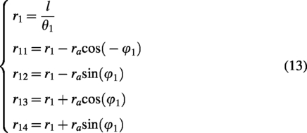
In the expression rij, i and j represent the jth-driven flexible cable of the ith joint group; l denotes the distance between the central axes of two adjacent joint modules, and r1 represents the radius of curvature of the central axis arc.
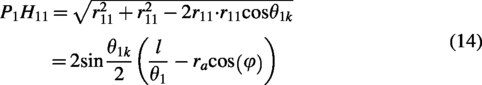
The distance between two joint modules within the joint group is considered the fundamental unit of study to facilitate analysis and reduce errors arising during the geometric analysis process. By establishing the mapping relationship between the bending deflection angle of the joint module and the end pose, we conduct a kinematic analysis of the driving space and joint space for a single-segment joint group. The curvature radius of each driving cable can be calculated from Equation (13), and the length of the driving cable between the two joint modules can be determined using the law of cosines. In addition, we divide each joint segment into k (where k = 3) joint modules, with each joint module having the same bending and deflection angles (the bending angle of a single joint module can be represented as θ1
k
= θ1/k). Taking the driving cable l11 as an example, the length of a segment of the cable P1H11 is calculated within the isosceles triangle M′P1H11 (Fig. 4c), with the calculation formula provided in Equation (14).
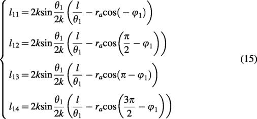
Based on the above analysis, it can be concluded that the total length of the driving cable is k times the length of the segment P1H11. Similarly, the lengths of the driven cables l12, l13, and l14 can be determined as shown in Equation (15). Furthermore, based on Equation (15), the impact of different joint bending and deflection on the change in the lengths of the driving cables can also be determined (Fig. 4d–g).
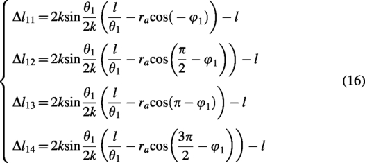
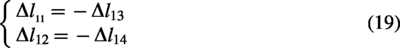
When the joint group is in its initial state, the bending and deflection angles are 0°. At this point, the length of the drive cable is equal to the arc length along the central axis of the joint assembly, both being l. When the joint group bends, the difference between the actual length of the drive cable and its initial length corresponds to the variation of each driven flexible cable in the drive circuit, calculated using Equation (16). A positive Δ value indicates that the drive cable is elongating, while a negative Δ value signifies that the drive cable is undergoing contraction.
The geometric relationship between Δl11 and Δl13 can be further derived from Equation (17), as shown in Equation (8). Let θ1/2k = x; further analysis can derive the relationship between Equation (17) and x, as expressed in Equation (18).

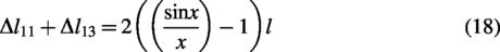
Based on the analysis presented above, it is observed that the maximum bending angle of a single joint module is 43°, while the maximum bending angle of a single joint group is 129°. Consequently, when the range of x is (0, 0.12π], the value of sin x/x approaches 1, allowing Equation (18) to be further derived into Equation (19).
Based on Equations (16) and (19), the forward kinematic mapping relationship between the driving space and the joint space of a single joint group can be derived as follows:
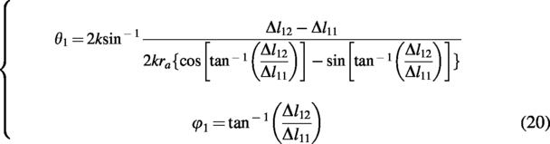
Furthermore, based on Equations (20) and (6), the driving motor can regulate the variation in driving cable length, thereby enabling control over the continuous bending and deflection angles of the robot’s torso. This establishes a theoretical foundation for the subsequent development of control algorithms for the robot’s flipping gait across various motion scenarios, including wall climbing, obstacle crossing, and surface-to-surface transitions.
The joint space and operational space of a multi-segment joint group
Based on the analysis of bending and deflection angles of the single-segment joint group, the forward kinematic mapping relationship between the joint space and the operating space of the multi-segment joint group is established. A base coordinate system is established at the initial joint module of each segment, while an end coordinate system is defined at the terminal joint module. Let

Equation (21) represents the kinematic mapping relationship between the joint space and the operational space of a multi-segment joint group. Based on the kinematic analysis of a single-segment joint group, the inverse kinematic relationship from the joint space to the operational space for the multi-segment joint group can be derived from Equation (22) as follows:
Moreover, in most continuous robots, there is a coupling relationship among the drive spaces of the various joint groups, where the drive space of a subsequent joint group varies in response to changes in the drive space of the preceding joint group. The developed flipping continuous wall-climbing robot employs distributed independent actuation for the joint groups in each segment of its torso, with no coupling relationships existing between the various joint groups. Therefore, when the preceding joint group undergoes bending deflection, the driving space of the subsequent joint groups remains unchanged.
Robot workspace
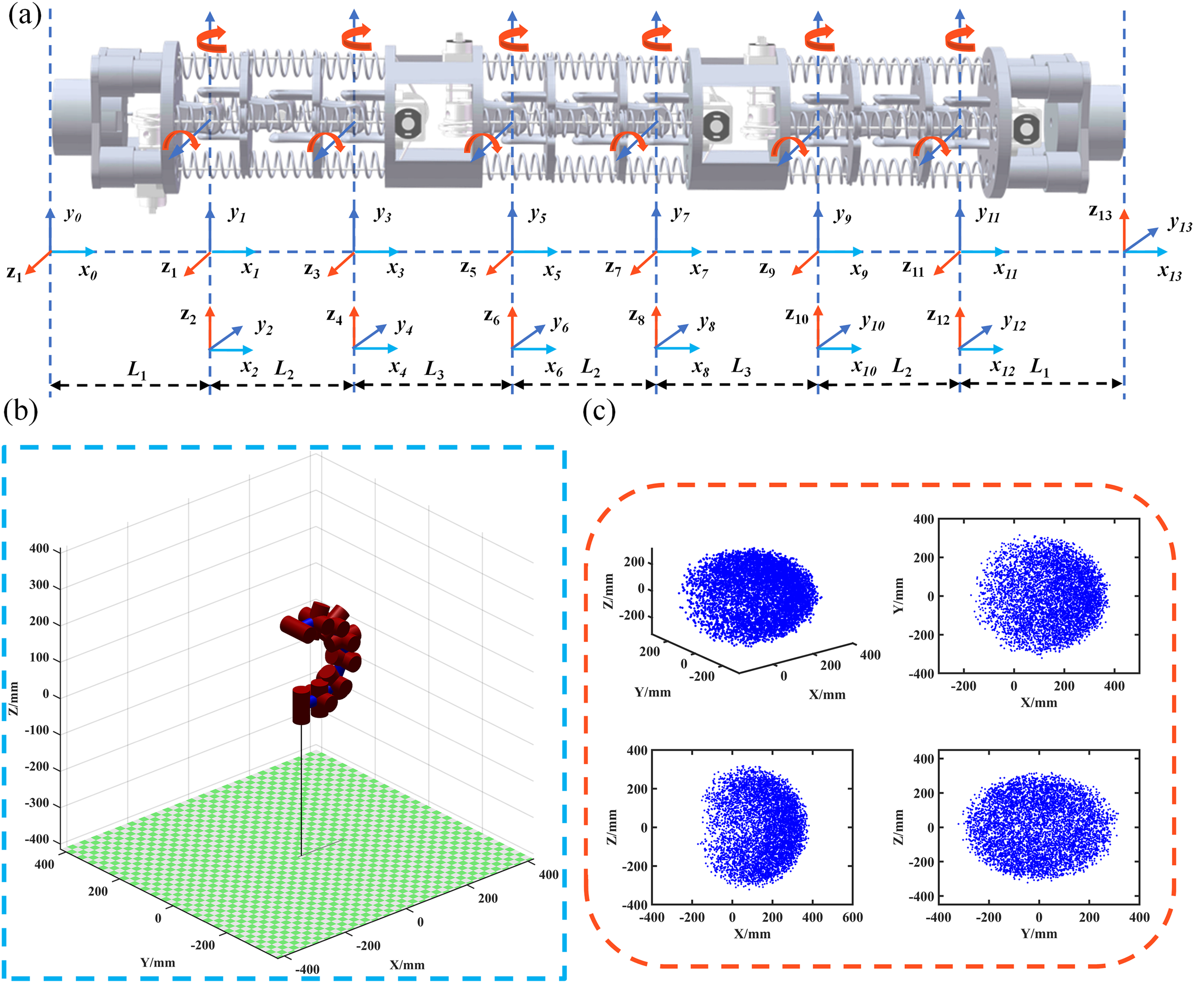
To better illustrate the motion capabilities of the robot and to determine its workspace, we replaced the bending of the two actuator loops in the joint groups with rotations about the y-axis and z-axis, establishing a simplified kinematic model for the continuous wall-climbing robot (Fig. 5a). Assuming that each segment of the joint group bends uniformly across all driving loops.
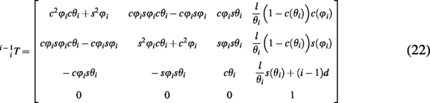
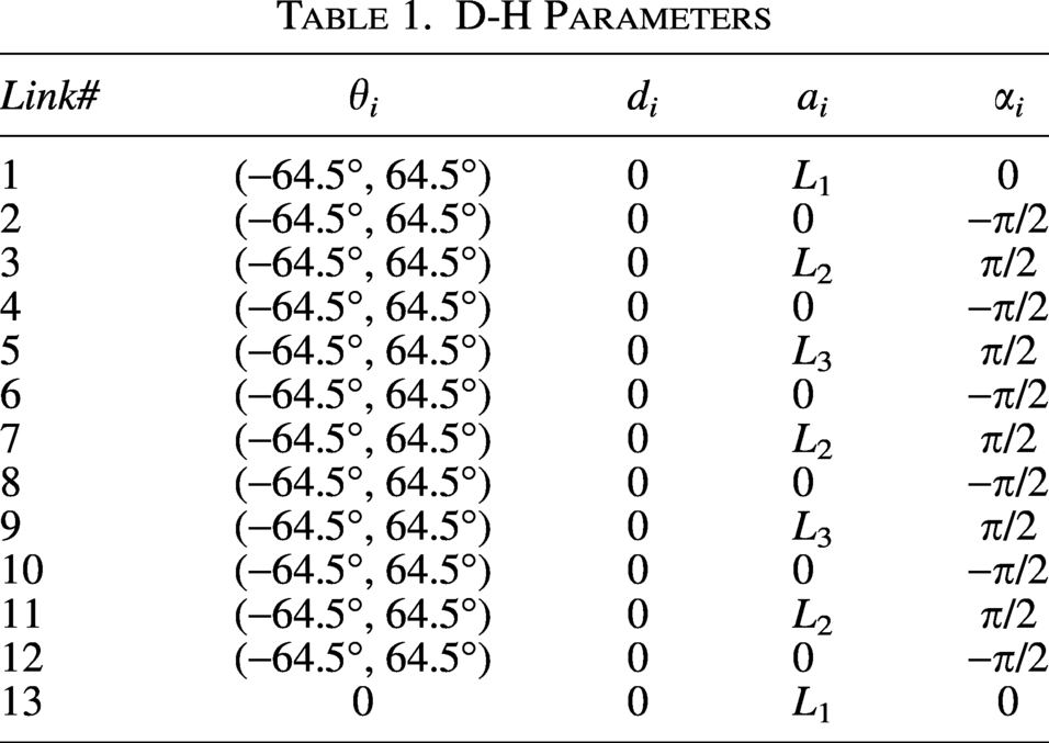
Let θi represent the bending angle of a single driving loop, L1 denotes the length of the adhesion module (L1 = 60 mm), L2 indicates the distance between adjacent joint modules (L2 = 56 mm), and L3 represents the length of the connecting module (L3 = 63 mm). In addition, L1 to L3 also represent the lengths of the connecting links between the joints. Assuming that one end of the robot’s adsorption module serves as the coordinate origin, we can obtain the coordinates of the end effector by establishing 13 coordinate systems and compiling the D-H parameter table (as shown in Table 1).
D-H Parameters
The transformation matrix from coordinate system i − 1 to coordinate system i can be expressed as Equation (22). The pose relationship of the robot’s end effector coordinate system relative to the base coordinate system can be described using the matrix 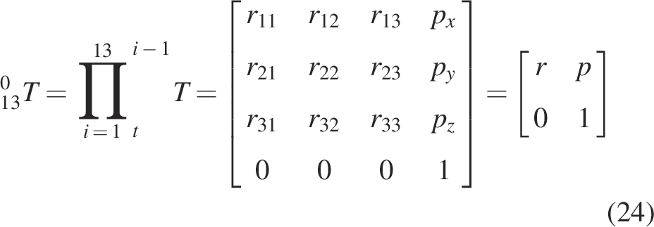
Based on the analysis above, the reachable workspace of the robot’s end effector can be determined by calculating the bending angle ranges of the three segments of continuous joint groups, as shown in Figure 5b, c. By controlling the bending and deflection angles of the three segments of joint groups, the robot can be adapted to operate in complex, unstructured work environments.
Results
Validation of theoretical models
To validate the theoretical bending angle model of the single-segment joint group (Equations 7 and 11), we experimentally measured the actual bending angles of the joint group under a single drive loop with varying lengths of flexible cables. In this experiment, an IMU sensor was mounted at the distal end of the joint group to measure its bending angle by acquiring sensor data. Figure 6 presents a comparison between the theoretical bending angle model and the experimentally measured bending angle of the single-segment joint group. The comparison results demonstrate that the theoretical bending angle model of the analyzed joint group aligns well with the experimental data. The discrepancy between the experimental results and the theoretical model can be attributed to two primary factors: deviations of the elastic coefficients of different springs from their theoretical values, and the exclusion of the frictional force between the flexible cable and the joint module in the model formulation.
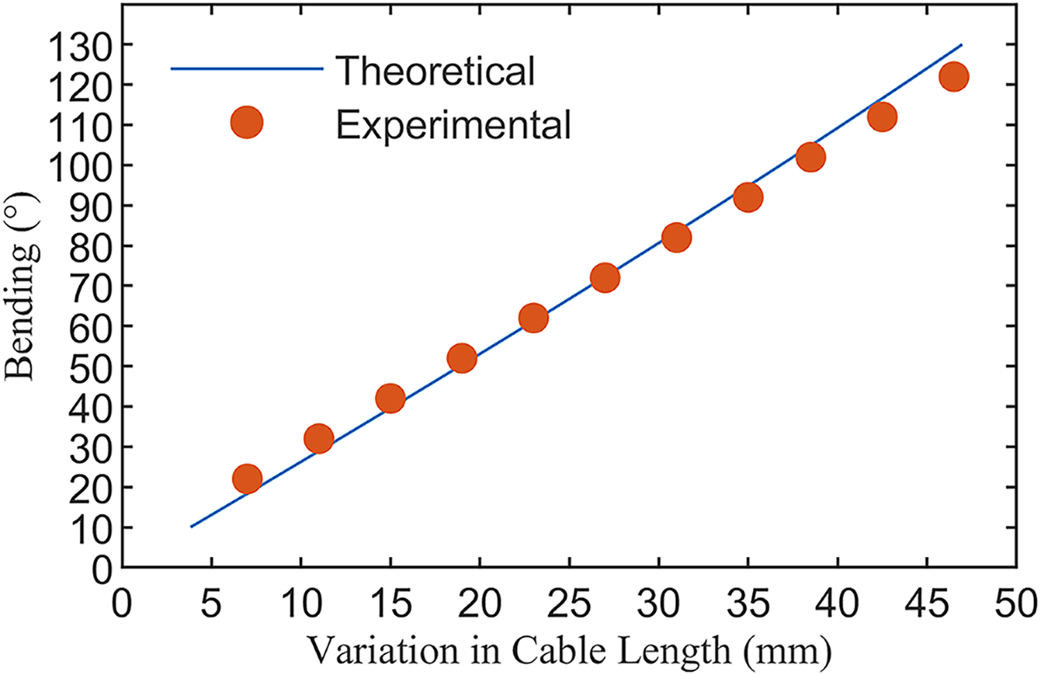
Comparison of the theoretical model of the bending angle of the joint group with the experimental results.
Electromagnet adsorption performance test
The maximum pull force of the electromagnet is not only related to its rated power but is also significantly influenced by the iron content and thickness of the material to be attracted, as given by the theoretical Equation (25). Therefore, it is essential to assess the adsorption performance of the electromagnet on typical iron-containing industrial materials and to determine its adsorption capacity under varying material thicknesses. To validate the adsorption performance of the electromagnet on typical iron-containing industrial materials, we chose Q235 steel (equivalent to ASTM A36), 35# steel (AISI 1035), and 45# steel (AISI 1045) as the experimental objects. In addition, to test the electromagnet’s performance at the thinnest condition, samples with a thickness down to 1 mm were employed in the experiments. The experimental results are shown in Figure 7. Considering that the robot is required to actively lift its own weight and carry loads for various applications, the minimum normal adhesion force required is 80 N, and the corresponding shear adhesion force is 25 N. The experimental results show that the robot can work with a minimum thickness of 2 mm for the three materials mentioned above, which further confirms that the robot can operate on industrially common iron-containing materials and under typical component thicknesses.
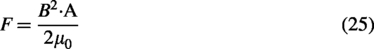
The normal and shear adsorption forces of the electromagnet on the surfaces of Q235 steel, 35# steel, and 45# steel under different material thicknesses.
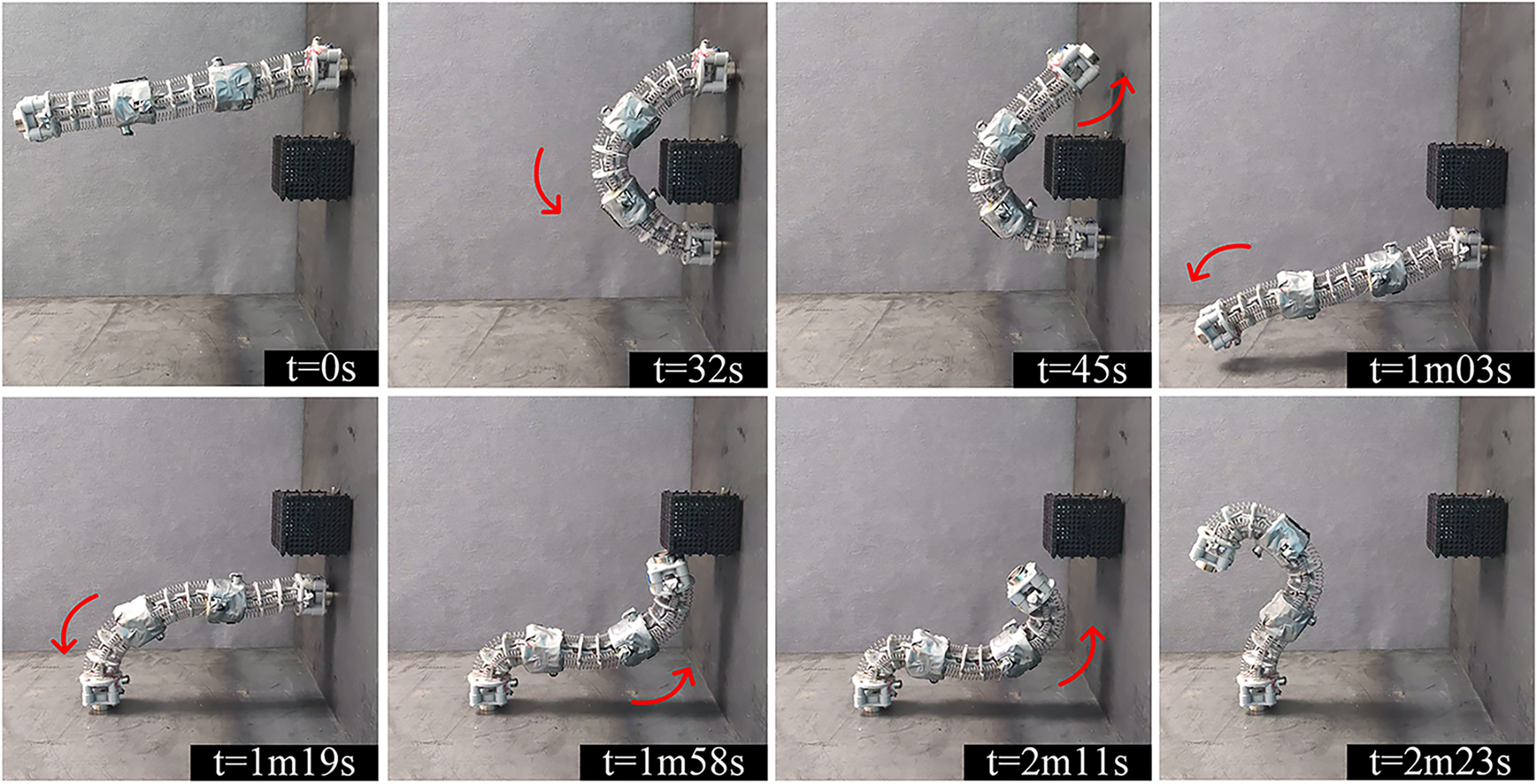
In Equation (25), B denotes the magnetic flux density in the air gap, expressed in Tesla (T), which is determined by the magnetic permeability of the material and the thickness of the adsorbed surface. A represents the magnetic pole area, which remains constant. μ0 signifies the vacuum permeability, a fundamental physical constant.
Characterization of the stiffness of the robot’s torso
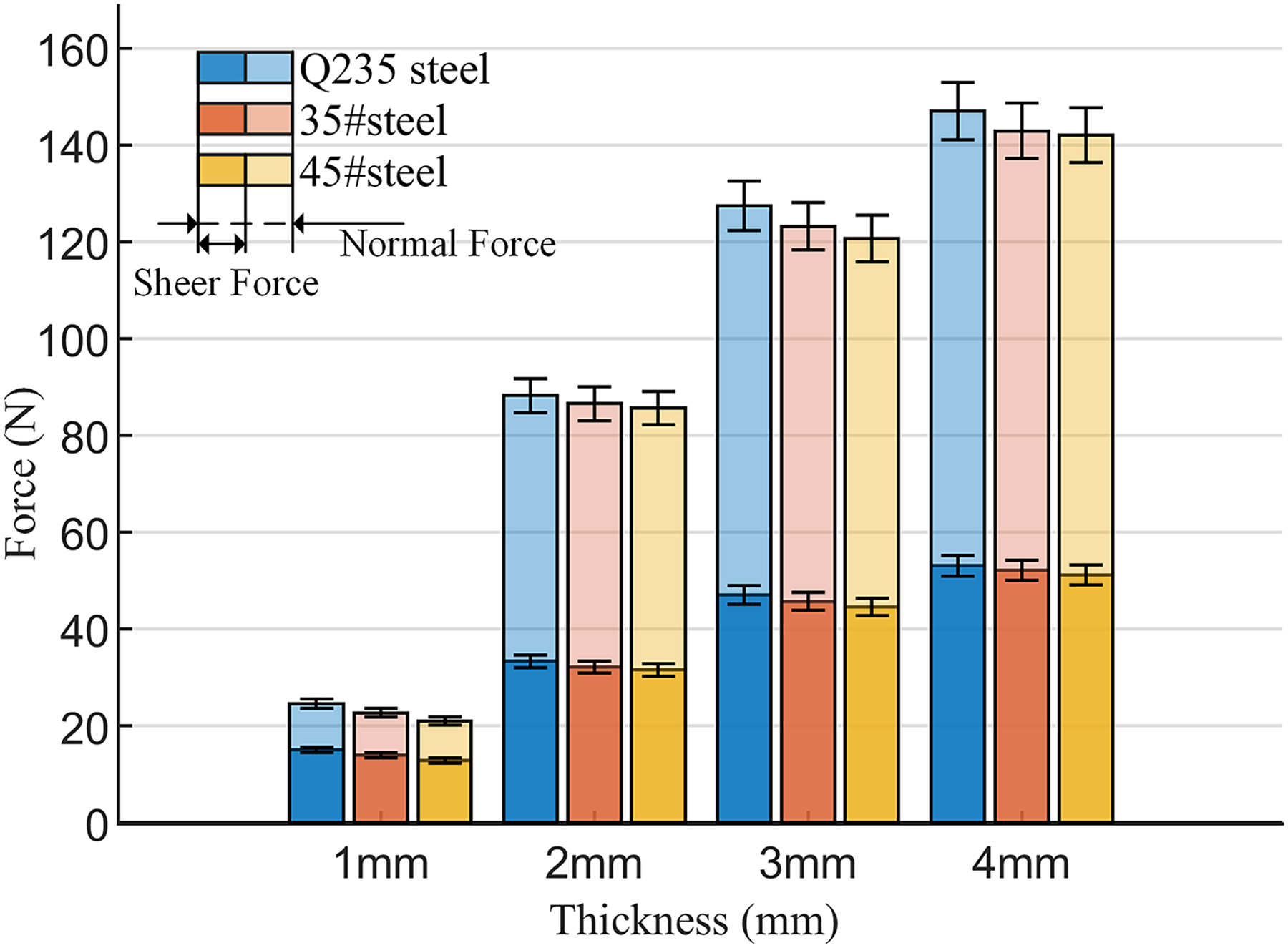
The inherent compliance of the continuous wall-climbing robot’s torso enables it to adapt well to complex unstructured environments. However, when the robot is required to carry heavy payloads or operate as a manipulator to perform tasks, the trunk cannot withstand large loads, necessitating an investigation into the torso’s stiffness. First, we analyzed the theoretical model of the stiffness of the robot trunk (Supplementary Data S3). Then, we tested the stiffness-variation characteristics of the robot in the upright state. The stiffness of the robot trunk was determined by applying a load at the end of the trunk and recording the resulting displacement. As shown in Figure 8, the comparison graph of the experimental test values and theoretical analysis values of the robot torso stiffness is presented. From the figure, the theoretical and experimental results for the robot torso stiffness are in good agreement. The discrepancy between the experimental and theoretical results may arise from neglecting the effect of the robot torso’s self-weight on stiffness and from manufacturing tolerances of the components.
Comparison of the theoretical model of torso stiffness with experimental results.
Fundamental motion capabilities
The fundamental motion capabilities of the wall-climbing robot demonstrate its ability to traverse vertical surfaces. These capabilities include wall-climbing, steering, movement between transitional surfaces, and obstacle-crossing. Owing to the flexibility and compliance of its continuous torso movement, the robot possesses multiple fundamental motion capabilities while maintaining a simple control strategy and a flexible torso. Supplementary Figure S5a (Supplementary Movie S1) demonstrates the robot’s wall-climbing capability on a vertical surface. When the robot performs a flipping motion against a wall, the joint group in the middle of the torso first bends, resulting in a reduction in torso length. This adjustment mitigates the adverse effects caused by gravitational torque, thereby enabling the robot to execute the upward flipping motion successfully. Supplementary Figure S5b (Supplementary Movie S2) illustrates the robot’s turning motion against a wall. The turning radius of the robot is constrained by the radius of its flipping gait, with a minimum turning radius of 150 mm (0.37 body length) and a maximum turning radius of 260 mm (0.63 body length). Supplementary Figure S5c (Supplementary Movie S3) illustrates the locomotion capabilities of the robot on a 270° transition plane. The robot’s torso can achieve large-angle compliant bending and execute flipping movements across a 270° transition plane with a bending speed of 3.75°/s. During the entire bending process of the torso, the bending angles of each joint group are controlled to manipulate the bending shape of the torso, enabling the robot to perform movements across large-angle transitional planes.
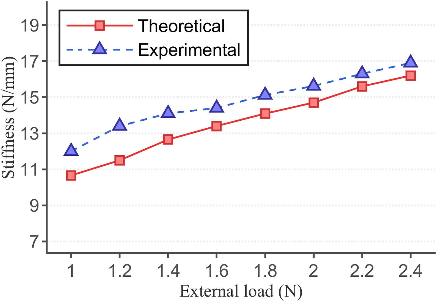
To assess the robot’s obstacle-crossing capability and to address the issue of excessive motion space required for the flipping gait, we designed a continuous motion experiment for the robot to evaluate its ability to adjust the torso in complex environments flexibly. The robot is required to traverse obstacles on a vertical wall and transition from the vertical surface to a horizontal plane. Figure 9 (Supplementary Movie S4) illustrates the continuous motion process of the robot. The robot first traversed the obstacle on the perpendicular wall. Then, the adhesion module at one end of the torso executed the transition between surfaces and adhered to the horizontal plane. At this point, there is an interference between the robot’s flipping motion space and the position of obstacles, preventing the completion of a flipping gait. By controlling the bending angle of the joint group near the impediment to the robot’s torso (exceeding 90°), the length of the robot’s torso is shortened, thereby altering the flipping gait motion space of the robot. There is no overlap between the robot’s flipping motion space and the obstacle’s position, allowing its torso to continue its forward flipping motion. Subsequently, the robot moves forward on the horizontal plane after crossing the obstacle. The size of obstacles that the robot can traverse is related to the length of the robot’s torso and the width and height of the barriers. The robot could traverse obstacles with a maximum height of 120 mm and a width of 30 mm.
The robot alters its movement space by controlling the bending angles of the corresponding joint groups, thereby achieving continuous motion from traversing obstacles on the wall surface to transitioning onto the plane (the dimensions of the obstacle are 120 mm in length, 72 mm in width, and 85 mm in height).
The above experimental results indicate that the flipping continuous wall-climbing robot possesses multiple fundamental locomotion capabilities. Furthermore, the robot’s torso demonstrates a flexible adjustment ability, addressing the issues of excessive movement space and complex environmental adaptability inherent to flip-type wall-climbing robots. Additionally, the maximum load of the robot on vertical surfaces is 520 g, which is approximately 1.02 times its own weight. The load analysis of the robot and the experimental results are presented in Supplementary Data S4.
Mobility in complex unstructured environments
To evaluate the robot’s adaptability in unstructured work environments, we configured three mutually perpendicular inner surface scenarios where the height of the right wall is greater than that of the left wall. Figure 10a (Supplementary Movie S5) demonstrates the continuous motion of the robot between the walls. The robot adapts its torso to the unstructured work environment by controlling the bending and deflection angles of each joint group. Each joint group consists of two independently controlled drive circuits, providing the entire torso with six independent degrees of freedom to adapt to complex unstructured work environments effectively.

To verify the robot’s extreme mobility capabilities in complex spaces, we established a continuous motion task to navigate through a hole with a diameter of 15 cm (0.37 body length) and traverse a thin plate with a thickness of 2 mm. Figure 10b (Supplementary Movie S6) demonstrates the robot’s motion as it traverses a narrow hole. Due to the fixed length of the adhesive modules at both ends of the robot’s body, these modules cannot bend. Therefore, when the robot moves across a transition plane at a large angle, the continuous joint group in the middle section of the body bends at small angles to extend the body’s length and accommodate the length of the adsorption modules. The experimental results demonstrate that the robot competes well when bending at large angles. The bending shape of the robot resembles a “Ω”, which allows the adsorption modules to attach to the opposite side of the thin plate, providing the capability for 360° movement across transition planes and the ability to traverse thin plates. Furthermore, the wall-climbing robot, which can move across transition planes at large angles, can significantly enhance its adaptability and traversability in unstructured environments by adjusting its dynamic posture.
To further validate the locomotive capacity of the continuous wall-climbing robot in confined spaces, we established a confined gap with a width W of 11 cm (0.27 body length) and a height H of 50 cm for the robot. At this moment, the width of the gap does not enable the robot to accomplish the flipping gait on one side of the wall. Hence, other motion gaits have to be taken into consideration. The design strategy of the robot’s torso, which consists of a series of articulated segments and a distributed arrangement of drive cables, enables the robot to not only achieve a flexible flipping gait but also exhibit various locomotion gaits, such as the inchworm gait and the twisting swinging gait. Figure 10c (Supplementary Movie S7) illustrates the process of the robot performing a twisting swinging motion while climbing a wall within a confined gap. During the upward swinging motion of the torso, the adsorption modules at both ends operate alternately, enabling the robot to perform a twisting swinging gait along the side walls of the confined space. Finally, the robot executed three twisting oscillatory gaits along the inner sidewall of the gap, successfully emerging from the gap with a height of 50 cm.
Flipping locomotion gait with a variable radius
According to the analysis based on Equation (6), the key to achieving the minimum flipping walking radius strategy for the robot lies in maximizing the bending angle of the middle joint segment of the torso. Figure 11a, b (Supplementary Movie S8) illustrates the process of the robot executing a minimal radius flipping walking maneuver, along with a schematic representation of the timing sequence of the control system. Initially, the robot’s torso is in the initial state, with the adsorption module at the base of the torso operational. Then, the joint group in the middle section of the torso is maximally flexed inward (clockwise) as indicated in the control system timing diagram from 0 to 14 s. At this point, the length of the robot’s torso in the direction of motion is minimized, with the torso length converted to vertical height. Finally, the adsorption module operates alternately, enabling the robot to achieve walking with a minimum flipping radius. The experimental results for the robot’s flipping gait indicate a minimum walking radius of 135 mm (0.33 times the body length) and an average speed of 3.68 mm/s.
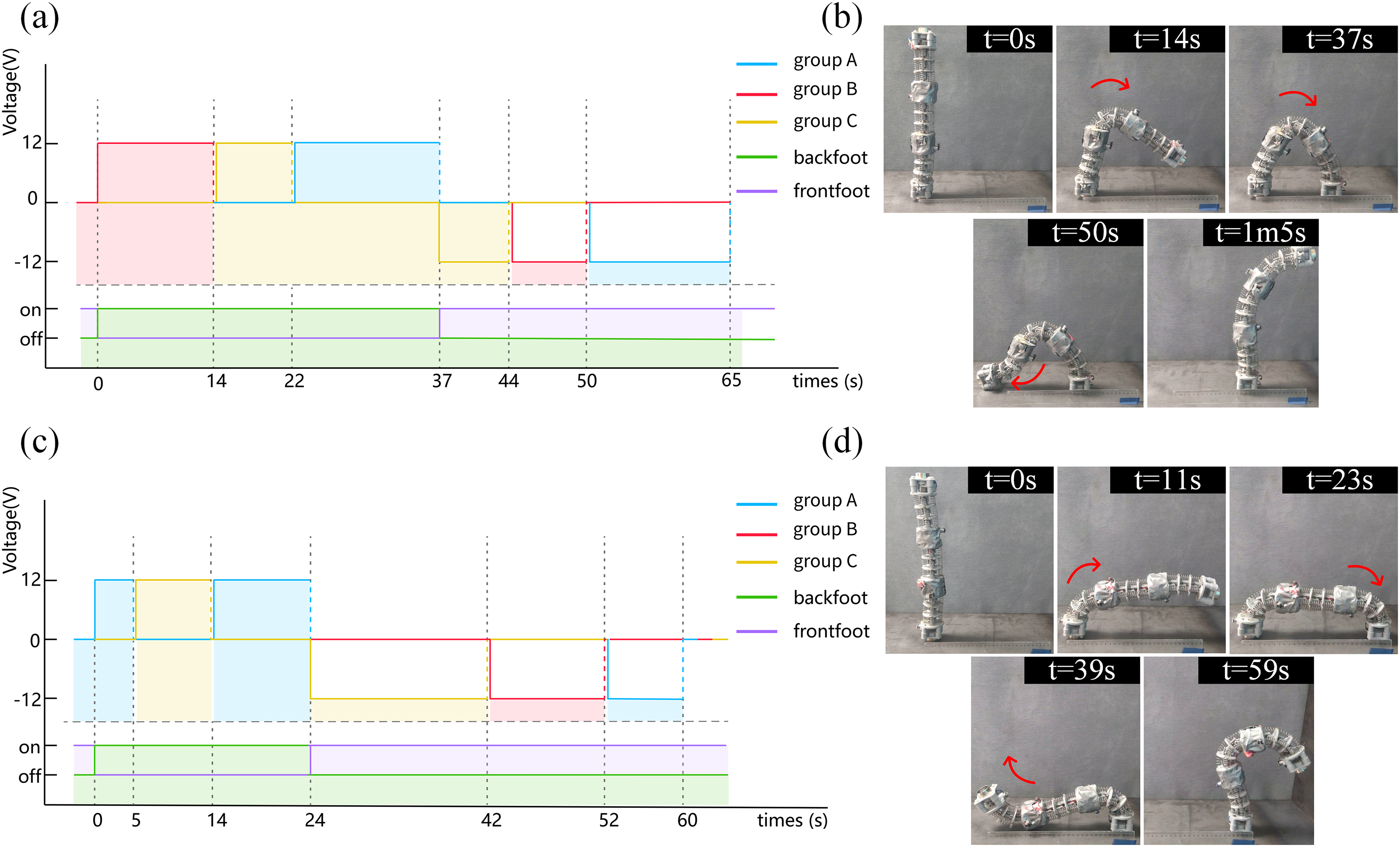
Experimental results of the robot’s variable-radius flipping walking.
Based on the analysis derived from Equation (6), the key to achieving the maximum flipping walking radius strategy for the robot is to minimize the bending angle of the middle joint segment of the torso. Figure 11c, d (Supplementary Movie S8) illustrates the process of the robot performing maximum radius flipping motion, along with a timing diagram of the control system. First, the robot’s torso is in its initial state, and the bottom adsorption module works. Then, the continuous joint groups at both trunk ends are bent inward (clockwise). At the same time, the continuous joint group in the middle section remained in its initial state (0–24 s in the control system timing diagram). At this point, the length of the torso in the direction of motion reaches its maximum, and the robot’s flipping radius during locomotion is maximized. Finally, the adsorption module completes the alternating adsorption process, enabling the robot to achieve the maximum walking radius during its flipping locomotion. The experimental results demonstrate that the robot achieves a maximum flipping walking radius of 260 mm (0.63 times its body length), with an average speed of 5.2 mm/s.
Based on the analysis of the aforementioned experimental test results, it is evident that the theoretical model of the robot’s maximum and minimum turning radius is consistent with the experimental findings, thereby validating the correctness of the theoretical model. The observed discrepancies between the experimental results and the theoretical predictions may be attributed to manufacturing tolerances in the components and angular deviations in the joint group bending.
Demonstration of potential applications
A wall-climbing robot with operational capabilities can effectively enhance the robot’s working efficiency and expand its body structure’s multifunctionality. The robot can attach one end of its torso to the wall surface and then utilize the torso as a flexible robotic arm to perform operational tasks. Figure 12a demonstrates the robot equipped with an industrial camera executing imaging tasks of both the pipeline's interior and side. Initially, the robot performed a flipping motion on the pipeline, allowing the adsorption module equipped with an industrial camera to move to the top of the pipeline. Meanwhile, the torso functioned as a flexible manipulator, enabling the camera to carry out the imaging task. Afterward, a pressure valve is located on the side of the pipeline, with its plane oriented perpendicularly to the bottom. For the industrial camera to capture the numerical readings on the pressure valve, the robot’s torso must bend over 90° toward the lower right corner. It can be observed from the experimental outcomes that when the robot reaches the top of the pipeline, benefiting from the six independent degrees of freedom of the robot’s torso, the torso is capable of driving the industrial camera to achieve active, flexible, and compliant direction changes, enabling the industrial camera to capture the values on the pressure valve precisely.

Furthermore, the robot can carry various detection devices, such as compact laser scanners, infrared thermal imaging cameras, and ultrasonic thickness gauges. These devices can be utilized in deformation and defect detection, lifespan prediction, and early fault warning of large steel structures.
Demonstration of robot collaboration capabilities
The collaborative motion and operational capabilities of multiple robots have become one of the trends in the future development of robotics.27,37 Benefiting from the flexible and lightweight torso of the continuous wall-climbing robot, along with the simple control method of electromagnets and their significant adhesion strength, these robots can achieve both serial and parallel cooperative movements.
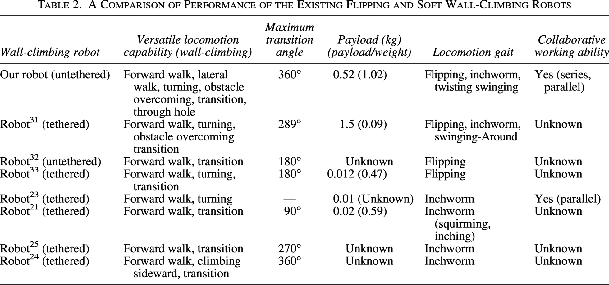
Figure 12b (Supplementary Movie S9) illustrates the movement process of two serially connected robots transitioning from an elevated platform to a horizontal plane, as viewed from both the front and side perspectives (step height: 35 cm). Initially, the two robots completed the serial docking procedure within the elevated platform region. Subsequently, during the transition of the two serially connected robots from the elevated platform to the horizontal plane, they alternately functioned as fulcrums. Finally, when the two robots in series moved onto the horizontal plane, they formed a new robot. At this stage, constrained by the load-bearing capacity of individual robots, two serially connected robots are unable to execute the flipping gait. However, two robots connected in series can adopt an inchworm-like walking gait to achieve movement. The experimental results demonstrate that two serially connected robots can improve their locomotion performance in unstructured environments through torso elongation. Furthermore, multiple robotic systems can be configured in parallel to further enhance the load-bearing capacity of the robotic system, as illustrated in Figure 12c. The robot possesses the capability of active serial and parallel configurations, surpassing the motion limits of individual robots, thereby enhancing overall motion performance. As presented in Table 2, our continuous wall-climbing robot demonstrates superior comprehensive mobility performance and enhanced collaborative operational capabilities compared with other wall-climbing robots.
A Comparison of Performance of the Existing Flipping and Soft Wall-Climbing Robots
In future research, we will further explore and expand the application scenarios of multi-robot collaborative motion. For example, the cooperative motion achieved through parallel and series configurations of multiple robots. For instance, multiple robots can achieve coordinated motion through a hybrid configuration combining parallel and series structures. First, two robots are connected in parallel to enhance the overall load-bearing capacity; subsequently, a third robot is integrated into the system through a series connection with the aforementioned parallel pair, thereby improving the third robot’s performance in obstacle-crossing tasks.
Conclusions and Future Work
This study proposes a magnetically adsorbed, flipping, continuous wall-climbing robot capable of navigating through complex, unstructured, and confined environments. Furthermore, we developed a simplified kinematic model to validate the kinematic characteristics of the robot. The robot’s untethered design is achieved through a distributed soft actuator configuration, incorporating built-in drive motors and batteries.
The experimental results demonstrate that the robot possesses multiple fundamental locomotion capabilities, enabling it to traverse between transition planes at an average speed of 3.75°/s, navigate through apertures with a diameter of 15 cm (0.37 body length), and perform wall-climbing maneuvers in confined spaces with a width of 11 cm (0.27 body length) under complex constrained environments. The robot exhibits a minimum flipping walking radius of 135 cm (0.33 body length) with an average speed of 3.68 mm/s and a maximum flipping walking radius of 26 mm (0.63 body length) with an average speed of 5.2 mm/s. It can also support an effective payload of 520 g (approximately 1.02 times its weight) on vertical surfaces. The robot can also carry compact sensors, enabling the active, flexible, and compliant steering of detection tools. We also demonstrated that two robots connected in series can successfully navigate a 35 cm high step, and that the same robots configured in parallel can transport an object weighing 1.1 kg. The ability of robots to maneuver in complex environments, along with the integrated design of mobility and manipulation, as well as the capability of multiple robots to collaborate in their movements, demonstrates significant potential for tasks such as rescue, inspection, operation, and reconnaissance in a complex, unstructured, and constrained environment.
This wall-climbing robot, featuring a continuous rigid-flexible combined body structure and the capability to locomote through flipping movements, offers novel insights and opportunities for enhancing the adaptability of crawling robots in complex and unstructured environments. There remain numerous research opportunities in future work that warrant thorough investigation. For instance, although existing wall-climbing robots demonstrate strong adaptability to unstructured environments, a body structure capable of enabling high-precision and high-load operations would significantly improve the robots’ operational efficiency and expand their potential application scenarios. Therefore, in the subsequent research work, we will study how to enhance the stiffness of the robot’s torso and improve the motion control accuracy of the end point of the torso. The current approach enhances torso stiffness through the implementation of high-stiffness connection springs and a reduced torso length, thereby improving both the robot’s load-bearing capacity and the precision of end-point motion control. Another potential avenue for improvement involves analyzing the fundamental gait dynamics of the robot and developing high-performance control algorithms tailored to its basic gait patterns. In addition, enhancing the robot’s environmental perception capabilities enables the development of a self-adaptive walking control system for operation in unstructured environments.
Authors’ Contributions
Y.S.: Conceptualization, methodology, formal analysis, validation, and writing—original draft. S.Y.: Investigation, experimental design, and project administration. H.D.: Visualization. W.W.: Methodology, writing—review & editing. L.Q. and P.L.: Investigation, data curation. H.Z.: Funding acquisition, resources, supervision, project administration, and writing—review & editing.
Footnotes
Author Disclosure Statement
No competing financial interests exist.
Funding Information
This work was supported by Sichuan Provincial Department of Science and Technology Key Research and Development Program in High-Tech Fields (2022YF G0240) and the Postgraduate Innovation Fund Project by Southwest University of Science and Technology (24ycx1101).
Availability of Data and Materials
The data used to support the results of this study are available from the corresponding author upon reasonable request.
Supplemental Material
Supplemental Material
Supplemental Material
Supplemental Material
Supplemental Material
Supplemental Material
Supplemental Material
Supplemental Material
Supplemental Material
Supplemental Material
References
Supplementary Material
Please find the following supplemental material available below.
For Open Access articles published under a Creative Commons License, all supplemental material carries the same license as the article it is associated with.
For non-Open Access articles published, all supplemental material carries a non-exclusive license, and permission requests for re-use of supplemental material or any part of supplemental material shall be sent directly to the copyright owner as specified in the copyright notice associated with the article.