
Abstract
Cable-climbing robots are essential for performing inspection and maintenance in hard-to-reach places with a cable-based infrastructure. However, current robots are often either cumbersome, have low load capacities or struggle to accommodate cables with largely varying diameters. To address these issues with a single design, this study demonstrates an origami-based, cable-climbing soft robot capable of caterpillar-like anchor-crawling locomotion. This robot weighs around 110 g and consists of a body mechanism and two leg mechanisms. The body mechanism with sufficient compliance can adapt to various bends of the cables. The leg mechanism utilizes a bionic gripping design that enables it to climb cables with diameters ranging from less than 1 mm to tens of millimeters. Additionally, the bistable performance of the leg mechanism allows the robot to secure itself to cables within a certain diameter range, even without continuous actuation. Moreover, the robot has a good load capacity and, for instance, can carry a load of more than ten times its weight on a vertical cable with a diameter of 30 mm. More capabilities of the robot are also demonstrated, including crawling between cables with different diameters, traversing protruding obstacles, transporting items, and completing complex tasks, such as repairing damaged cables.
Introduction
Cable-climbing robots are crucial for maintaining and inspecting infrastructure that relies on cables, such as power lines, suspension bridges, and communication towers. These structures often extend to great heights and remote locations, making manual inspection and maintenance dangerous, time-consuming, and costly. In particular, cables are widely used to transmit electricity, particularly ultra-high voltage cables connecting telephone poles or transmission towers. These cables can also generate electromagnetic interference (EMI) due to the high voltage they carry. By automating inspection and maintenance, cable-climbing robots enhance worker safety, reduce operational costs, and enhance efficiency, creating an urgent need for their design to assist in the inspection and maintenance of cable-supported infrastructure. However, most cable-crawling robots, to date, have been developed as rigid robots. These rigid robots can be used for cable-stayed bridges1–4 and high-voltage transmission lines.5,6 However, this type is heavy due to its rigid mechanisms, which can cause large deformation of the cables and may lead to serious accidents when slipping or falling occurs. Additionally, because these robots are electrically powered and controlled, EMI from high-voltage power lines can lead to issues with their control systems. 7
In contrast, cable-crawling soft robots made of soft materials and compliant structures offer several advantages of being lightweight, highly adaptable, and safe compared with their rigid counterparts. Several soft robots have been designed to climb thin cables,8,9 but their load capacity is very low (less than 0.1 N). Nonelectrically powered soft robots eliminate the necessity for cumbersome mechanical components and onboard electronic components, making them a promising option for climbing high-voltage lines. Pneumatic soft robots are the most representative, capable of handling practical payloads sufficient for object manipulation. These robots are made of flexible elastomers, so they have good insulation properties being immune to EMI from high-voltage power lines. They consist of inflatable chambers that can be inflated or deflated by pressurized air to generate various desired deformations for locomotion.10–12 Pneumatic soft robots based on different designs can achieve a variety of locomotion, such as crawling,13–18 tube-climbing,19–22 swimming, 23 and jumping.24,25 There are also rod-climbing robots inspired by the winding locomotion of snakes, but they can only climb rods within a small diameter range and have low load capacity. 26 In addition, pneumatic origami actuators are a type of soft actuator that integrates the principles of origami (i.e., article folding) with pneumatic actuation. Pneumatic origami actuators combine the advantages of soft actuators and rigid structures, allowing for lightweight and flexible designs that can produce large deformations and strong forces simultaneously.27–30 In different types of origami, the Kresling pattern is a specific type of origami that allows Kresling origami actuators to produce linear axial deformation coupled with a twist from the relative rotation between the two ends of the actuator.31,32 By adjusting the geometric parameters of the Kresling, the origami actuator can be designed to exhibit either monostable or bistable characteristics with specific mechanical properties.33,34 These characteristics demonstrate the potential of pneumatic origami actuators for cable-climbing robots; however, such robots are still underdeveloped.
This study demonstrates an origami-based, cable-climbing pneumatic soft robot with potential applications of inspection and maintenance in hard-to-reach places of cable-based infrastructure. Compared with existing cable/rod-climbing robots, the proposed robot demonstrates high climbing speed, large load capacity, suitability for climbing cables of various diameters, and the ability to overcome obstacles. The robot consists of a body mechanism containing two symmetrically arranged body actuators and two leg mechanisms, each containing four symmetrically arranged leg actuators. All actuators are Kresling-based origami soft actuators, which can be designed to be either monostable or bistable depending on different geometries. The body actuators are monostable, enabling the body mechanism to have sufficient flexibility and compliance to adapt to various bends in the cables, while the leg actuators are bistable, allowing the leg mechanism, through its claws, to achieve quick grabbing and releasing from the cable, or to stay on the cable even without requiring continuous actuation. The leg mechanism utilizes a bionic gripping design that enables it to climb cables with diameters ranging from less than 1 mm to tens of millimeters. The coordinated motion of the body mechanism and the leg mechanisms enables the robot to achieve a caterpillar-like anchor-crawling locomotion that can reach a maximum speed of 0.81 body lengths per stride. The capabilities of the robot are also demonstrated, including crawling between cables of varying diameters, traversing protruding obstacles, transporting items, and completing complex tasks like repairing damaged cables.
Results
Robot design and locomotion principle
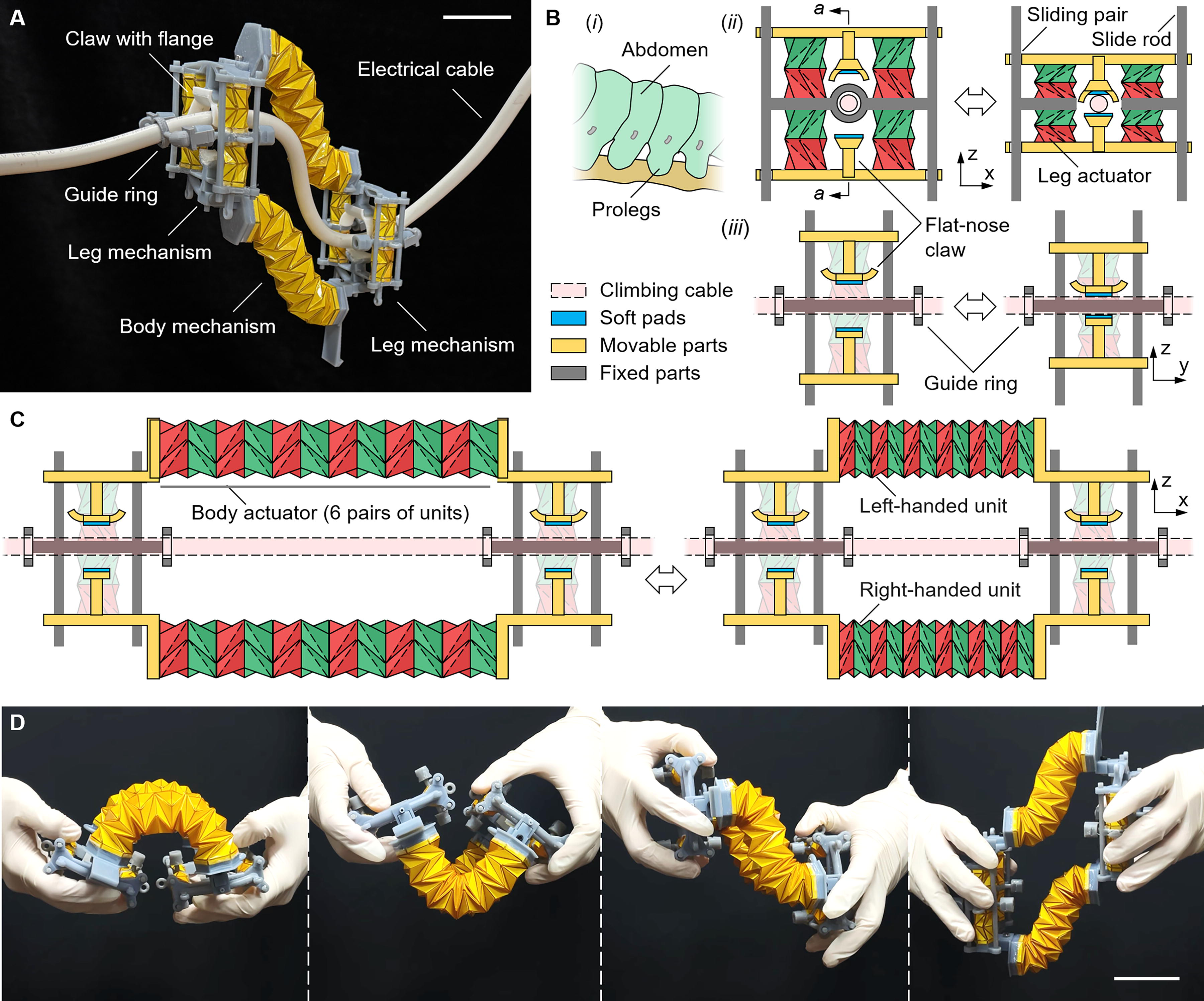
The robot consists of a body and two identical, mirror-symmetrical leg mechanisms at each end (Fig. 1A). According to the forward movement direction of the robot, the leg mechanisms are referred to as the front leg mechanism and the rear leg mechanism. Inspired by the caterpillar’s prolegs that grasp branches, the robot’s leg mechanism also consists of two flat-nosed claws to grasp or release cables, even those with very small diameters (Fig. 1B). The upper claw is fitted with an additional cross-shaped hyperboloid flange. The outward-curving portions of the flange, aligned with the cable direction, enable the robot to overcome certain protruding obstacles. The inward-curving portions of the flange, which are perpendicular to the cable direction, allow the cable to slide toward the center of the claw for a secure grip in the center position of the claws. A soft pad is attached to the center of each claw to increase the friction between the claw and the grasped cable. The motion of each claw is actuated by two symmetrically arranged leg actuators. Each leg actuator is composed of one paired Kresling origami unit with an opposite chirality. The paired Kresling units, upon simultaneous pressurization or depressurization, can achieve pure linear motion (i.e., contraction or expansion) between the two ends. Additionally, the Kresling unit can be designed to be monostable or bistable depending on the design parameters, thereby achieving the different mechanical properties required for the robot’s body and leg mechanisms (Supplementary Fig. S1). Bistable Kresling units are used for the leg actuators to achieve quick grabbing and releasing due to rapid snap-through transitions between two stable states upon depressurization or pressurization. Moreover, these bistable Kresling units can provide a self-locking property to the leg mechanism. This self-locking property of the legs enhances safety by preventing the robot from accidental slipping or falling. It also increases reliability by resisting loosening from vibration, eliminating the need for additional braking components. One end of a pair of leg actuators is fixed to the frame of the leg mechanism, and the other end, that is, the movable end, is fixed to the claw. Therefore, pressurizing or depressurizing both leg actuators simultaneously can drive a single claw to translate on the slide rod through the sliding pairs. As a result, synchronously controlling the four leg actuators of a pair of claws can make a pair of claws tighten or loosen the cable.
Design and working principles of the cable-climbing robot.
Each leg mechanism is equipped with guide rings at both the front and back. Because the two claws of the leg mechanism no longer contact the cable after releasing the cable, guide rings are needed to prevent the robot from falling off the cable. Each guide ring is a detachable module, and each ring has a breakpoint for easy placement over closed cables. The modules of the guide rings are designed with different inner diameters so that the leg mechanism can stably grasp the cable with a diameter slightly smaller than the inner diameter of the guide ring. This replaceable modular design allows for easy replacement of the guide ring, enabling the robot to crawl through cables with diameters ranging from less than 1 mm to several tens of millimeters. It is worth noting that the maximum diameter of the cable that the claw can grasp depends on the deformation of a single leg actuator, that is, the deformation of a pair of Kresling units. Therefore, by increasing the number of pairs of Kresling units within the leg actuator, the claw (with larger guide rings) can be enabled to grasp cables with much larger diameters. The robot body consists of two linear Kresling assemblies, each called a body actuator (Fig. 1C). Each actuator is composed of six paired Kresling units with opposite chirality. Conversely, monostable Kresling units are used for the body actuators to achieve smooth and continuous deformation upon pressurization or depressurization and to obtain a compliant structure of the robot body. The structural flexibility of the robot body enables the robot to easily adapt to various bends in the cables (Fig. 1D, Supplementary Movie S1). Eventually, both ends of each body actuator are rigidly connected to the movable ends of the front and rear leg actuators, respectively, thus forming the robot structure.
Materials and Fabrication
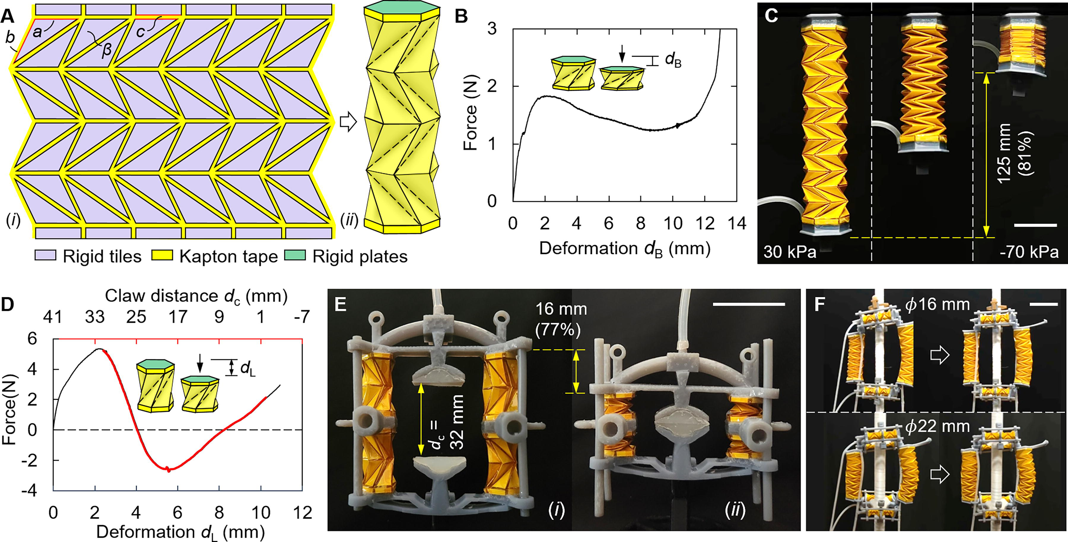
To fabricate an origami leg or body actuator, a polyvinyl chloride (PVC) sheet (0.2 mm thick) was first cut into identical triangles and rectangles using a cutting machine (Cameo 4, Silhouette). The dimensions of these triangles are defined by the lengths of their two shorter sides, a and b, and their included angle, β. These triangles and rectangles were then pasted to a Kapton tape (0.05 mm thick, BLEX) with an adjacent spacing of c = 1.2 mm, according to the Kresling pattern (Fig. 2A). After that, another layer of the same tape was pasted on top to form the thin-layered structure. The areas containing PVC are sandwich structures that form the facets of the Kresling units, and the areas without PVC are bonded by two layers of tape to form the creases. The layered structure is then rolled, and the ends are taped together using the same tape to form a tube. Then, the Kresling-patterned origami structures are formed by manually folding the tube along with the creases. The pneumatic actuators (either leg actuators or body actuators) were ultimately constructed by sealing the Kresling structure with rigid upper and lower polygonal plates made of resin (hard tough resin, eSUN) fabricated via 3D printing (Photon Mono X, Anycubic). The side lengths of the polygonal plates of the body actuator and leg actuator are 17.3 and 8.6 mm, respectively, and the corresponding areas are 777.6 and 192.1 mm2. Moreover, previous studies have shown that when the origami actuator is unfolded to a height close to the maximum unfoldable height, it produces an irreversible buckling deformation even under very small positive air pressures. 35 Therefore, to allow the actuator to withstand a certain positive air pressure without causing a buckling deformation, a nonstretchable, thin string, with a length less than the maximum unfoldable height of the origami actuator, is used to connect the upper and lower polygonal plates to prevent the origami actuator from unfolding to the maximum unfoldable height.
Design and performance evaluations of the origami actuators.
The rest of the rigid structure is also made with the same 3D printer using the same material. Finally, all the components and actuators are assembled to form the robot. The specific parameters of the robot structure are summarized, as shown in Table 1. It is worth noting that the four leg actuators of each leg mechanism are interconnected with air pipes, and the two body actuators are also interconnected with air pipes, so as to achieve synchronous actuation. The air pressure in the three sets of actuators can be controlled independently through a customized control system (Supplementary Fig. S2). The desired positive pressure for the actuators is realized by controlling the compressed air through an electro-pneumatic regulator (ITV0030, SMC), and the desired negative pressure is realized by controlling the vacuum through an electronic vacuum regulator (ITV0090, SMC). The required positive and negative air pressures are applied to the designated actuators through the solenoid valves (VX220EA, SMC) to control their deformation, and then the front leg mechanism, rear leg mechanism, and the body mechanism are driven by three sets of such devices, respectively.
Main Parameters of the Robot
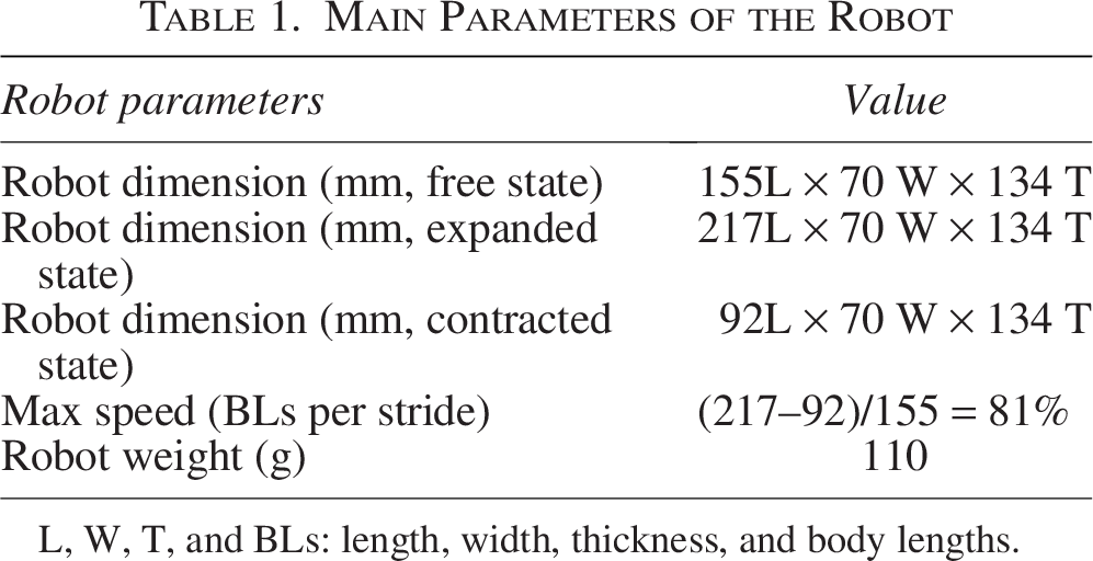
L, W, T, and BLs: length, width, thickness, and body lengths.
Mechanical performance of the origami pneumatic actuators
(1.4) By adjusting the length ratio (b/a) of the two shorter sides of the triangular plate, the actuator can be designed to be monostable (bounded by 0.5
In contrast, the leg actuator is designed to be bistable (b/a = 1.5), with parameters a, b, and β measuring 7.2 mm, 10.9 mm, and 101°, respectively (Supplementary Movie S2). The bistable characteristic is verified through a similar compression test. The compressive force (i.e., the reaction force of the unit on the load cell) corresponding to the displacement was measured and recorded (Fig. 2D). The compression curve separates into three distinct segments. During the first segment (i.e., the first stable state), the reaction force remains positive and does positive work. The reaction force increases fast to reach a peak value of 5.3 N at about 2 mm, and then decreases to 0 N at about 4 mm. During the second segment (i.e., the second stable state), the reaction force becomes negative and does negative work. The reaction force continues to decrease to reach a valley value of −2.7 N at about 5.5 mm, and then increases to 0 N at about 8.2 mm. In the third segment, the compression force increases from 0 N. The red-highlighted portion of the curve, ranging from 2.4 to 10.4 mm, is the part used for the deformation of the leg actuator. Similarly, the maximum deformation of 10.4 mm from its fully expanded state is achieved by a negative pressure of −70 kPa, and the minimum deformation of 2.4 mm from its fully expanded state is caused by the restriction of the embedded string under the positive pressure. The length of each leg actuator (containing one pair of Kresling units) is ∼20.7 mm (constrained by an embedded string) at a fully inflated state and ∼4.7 mm at a fully contracted state, with a corresponding length change of about 16 mm (i.e., the maximum stroke of each claw) with a length change ratio of 77% (Fig. 2E).
The leg actuator’s first stable state allows the maximum opening of the two claws to be 32 mm to accommodate the high-voltage cables whose diameters are usually between 20 and 30 mm (Fig. 2E). That is, the robot can grasp cables with a maximum diameter of 32 mm. It is worth noting that by increasing the number of Kresling units in the leg actuator, the claws can have a larger opening, thus enabling them to grip cables with a larger diameter. The actuator’s second stable state imparts a self-locking property, enabling the leg mechanism’s claws to fully close or anchor on a cable of a specific diameter without the requirement of continuous actuation of the leg actuators. To anchor on the cable, the negative forces generated by the leg actuator are applied to the cable through the claws as normal forces, thus providing a resultant friction force greater than its gravity or the component of gravity along with the cable. Based on a friction coefficient of 0.8, experiments show that the robot can anchor on vertical cables with diameters between 16 and 22 mm. Figure 2F shows the robot anchoring on cables with diameters of 16 and 22 mm, respectively. It is worth noting that the maximum diameter of the cable that the claw can grasp depends on both the opening size of the claws and the inner diameter of the guide ring. Therefore, by increasing the number of pairs of Kresling units within the leg actuator and the diameter of the guide ring, the claw can be enabled to grasp cables with much larger diameters.
Locomotion performance
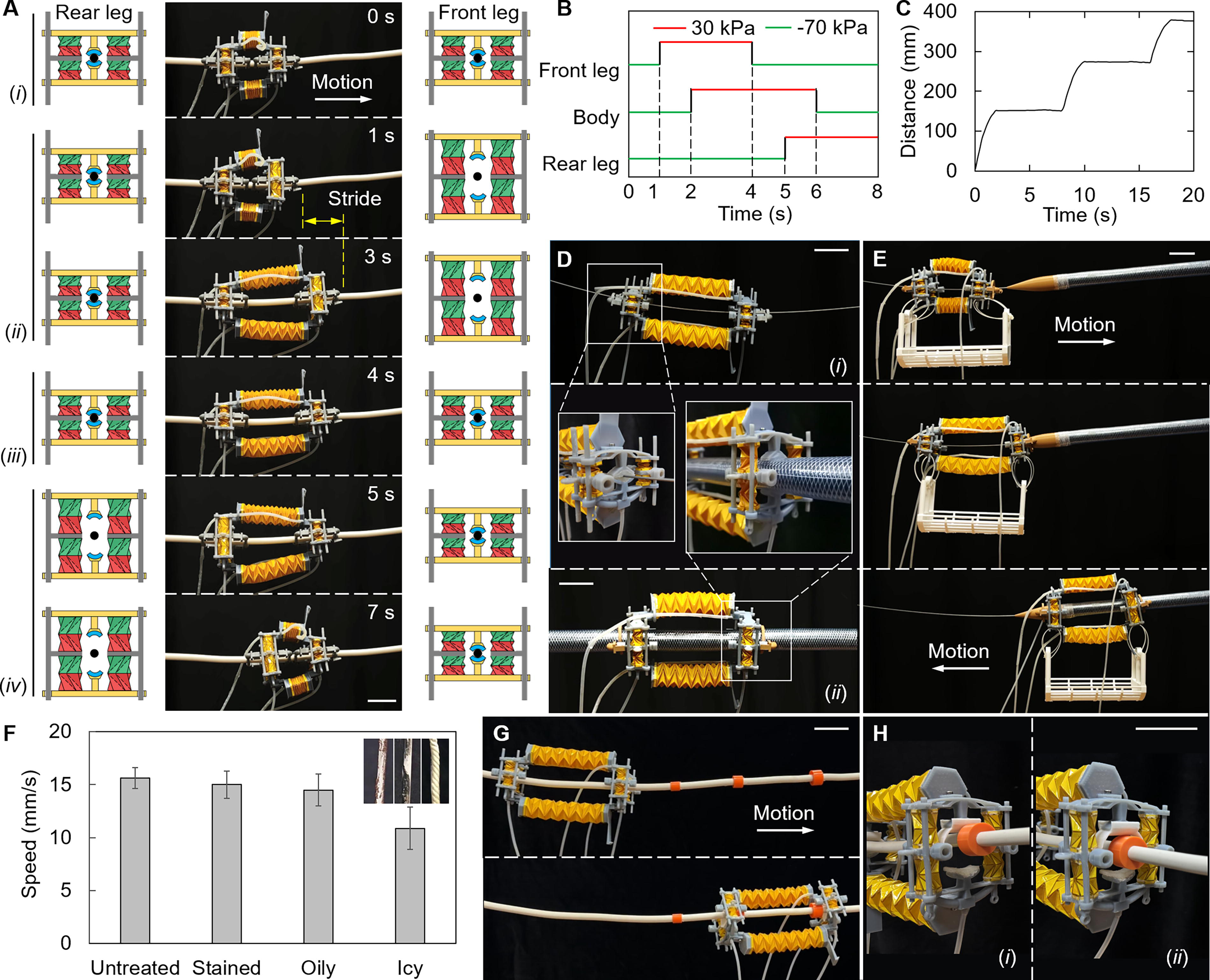
The robot’s motion is based on the anchor-motion crawling principle, similar to that of some caterpillars. To complete a stride, the robot needs to use its front and rear legs sequentially for anchoring (tightening the cable) during body contraction and expansion. That is, one stride of the robot consists of two main processes: anchor-pull and anchor-push. The performance of the linear locomotion was conducted on a cable with a diameter of 13 mm (Fig. 3A, Supplementary Movie S3). The actuation pattern with a single stride of 8 s is illustrated in Figure 3B. The period is set to 8 s to demonstrate the robot’s motion, but it can be shorter if the actuator is inflated or deflated more quickly. Each stride can be divided into four substeps, mainly of (i) anchor-anchor, (ii) anchor-push, (iii) anchor-anchor, and (iv) anchor-pull. Initially, the robot holds onto the cable with both its front and rear legs in an anchoring state. Then, the actuators in the front legs are inflated to release the cable from the front leg. Then, the body actuators are inflated to extend the body while simultaneously pushing the front leg forward. After that, the actuators in the front leg are deflated again, allowing the front leg to regrasp the cable. Next, the actuators in the rear leg are inflated to release the cable from the rear leg. Finally, the body actuators are deflated to contract the body while simultaneously pulling the rear leg forward; this process completes the motion of one stride. It is worth noting that the front leg and the back leg cannot release the cable at the same time to prevent the robot from sliding or rotating along with the cable. Figure 3C shows that the robot moved for three strides for a total distance of about 380 mm with an average speed of 0.81 BLs per stride (i.e., 16 mm/s). The robot can also crawl cables with diameters ranging from very small (even less than 1 mm) to the maximum opening size of its two claws. Figure 3D shows the robot crawling on cables with a diameter of 0.5 and 32 mm. In addition, Figure 3E illustrates the transition of the robot between cables with diameters of 0.5 and 32 mm (Supplementary Movie S4).
Motions of the robot on straight cables.
The crawling speed of the robot depends on its effective stride length. Some slippage may occur at the anchored legs, which can reduce the overall stride length. The amount of slippage is affected by the gripping force of the claws on the cable and the coefficient of friction (COF) between the soft pad of the claw and the cable. Maintaining a consistent gripping force (by keeping the air pressure applied to the leg actuators the same), the robot’s movement speed was measured on vertical cables with a diameter of 13 mm. These cables were treated in various ways: untreated, stained, oiled, and iced (with the iced cables being water-soaked and frozen cotton ropes of the same diameter used as a substitute). The results show that as the cable surface becomes smoother, the robot experiences more slippage during movement, reducing its average speed (Fig. 3F, Supplementary Fig. S4, Supplementary Movie S5, see Supplementary Data for the simplified kinematic model). The robot shows the lowest average speed on the icy surface (approximately 10.8 mm/s) because this surface represents the most slippery condition, providing the lowest COF. In addition, the outward-curving portions (i.e., a 70° arc with a radius of 15 mm) of the flange of the upper claw, aligned with the cable direction, enable the robot to cross protruding obstacles. This performance was verified by testing the robot’s ability to slide over a step of a specified height (Fig. 3G and H). The step heights were determined by mounting ring-shaped obstacles of varying thicknesses on the crawling cable with a diameter of 11.5 mm. The results indicated that when an air pressure of 30 kPa was applied to the body mechanism, it was able to slide over a step with a maximum height of 6.8 mm (Supplementary Movie S6). The robot’s obstacle-crossing ability can be further improved by increasing the air pressure applied to the body actuators or by using a smoother flange section.
The flexibility and compliance of the robot’s body structure make the robot suitable for crawling on curved cables (Fig. 4A). To test this ability, experiments were conducted to enable the robot to crawl through a 13-mm diameter cable with a 120° bend. The transition section of the cable is an arc with different bending radii. The experimental results show that the minimum curvature radius that the robot can successfully crawl through is ∼34 mm (Fig. 4B, Supplementary Movie S7). The robot achieved a slip-free speed of 15.6 mm/s under the allowable curvature, which is almost the same as its horizontal linear motion speed. This minimum radius depends on the overall size of the robot and the distance between the two guide rings of the same leg mechanism. If these dimensions are reduced, the robot will be able to cross a smaller radius of curvature.
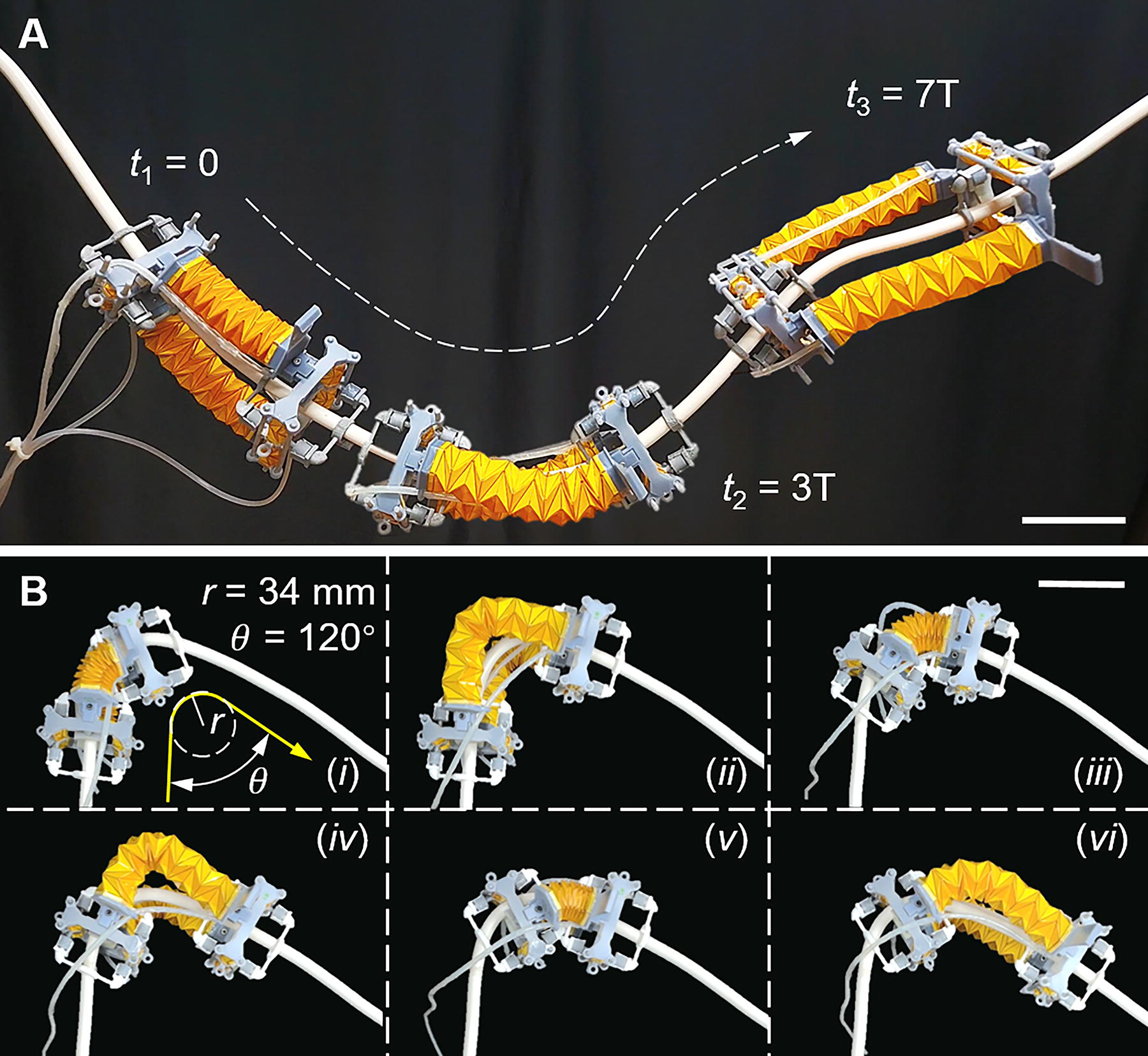
Motions of the robot on curved cables.
Payload performance on vertical cables
The robot’s load capacity in the most challenging vertical direction depends on the contraction forces provided by the two body actuators on the one hand and the friction provided by a single leg mechanism on the other hand. All these forces are related to the axial force generated by a Kresling unit; therefore, a simple model based on the geometries was built to calculate the axial force under the applied pressure (Fig. 5A). The two identical hexagonal bases and a Kresling unit form a closed cavity, and θ = 60° is the central angle corresponding to one side of the hexagon. Moreover, R, the radius of the hexagonal base, is 8.6 and 15.9 for the body actuator and leg actuator, respectively. Based on these fabrication parameters, the initial staggered angle 

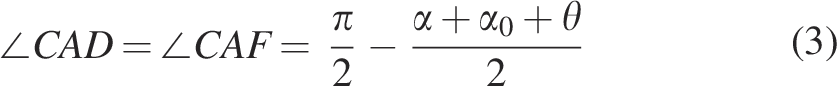
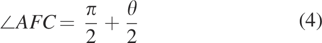
Then, based on the law of sines in 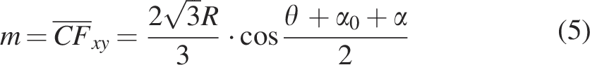
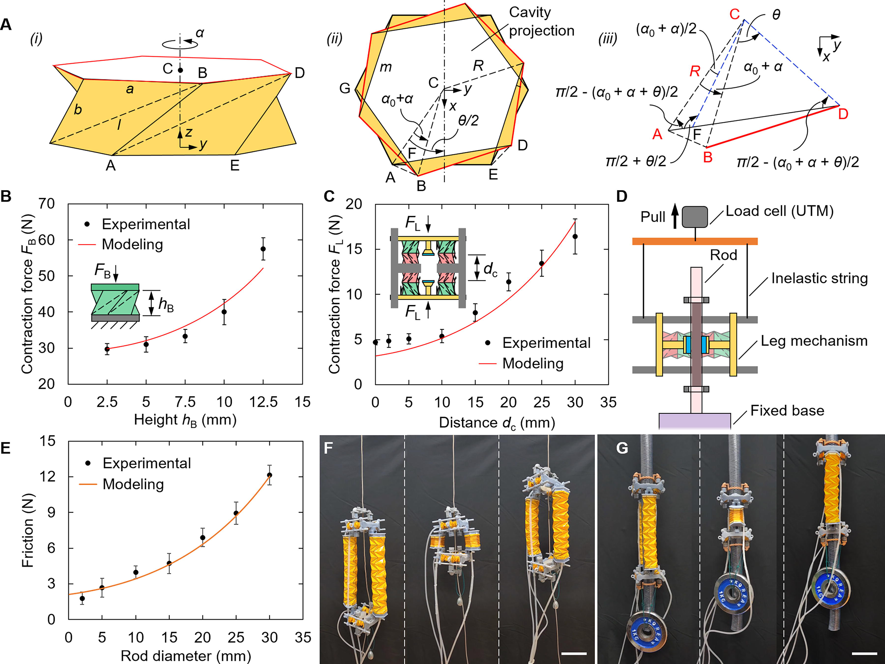
Payload capacity of the robot on vertical cables.
As the Kresling unit contracts, the projected area of its internal cavity continues to decrease, so that the contraction force generated under constant negative pressure continues to decrease. Related experiments were also conducted. Figure 5B shows the contraction force generated by a Kresling unit (of the body actuator) at −70 kPa. The results showed that even when the actuators were fully compressed at about 2.5 mm, the unit could still generate a minimum contraction force of approximately 30 N. Figure 5C shows the contraction force of two pairs of Kresling units at −70 kPa that actuate a claw. As the units contract, the contraction force decreases, which means that the gripping force decreases as the distance between the two claws decreases. When the contraction of units reaches 2.4 mm (i.e., when the two claws are fully closed), the contraction force can still reach 5 N, making it possible for the claws to grasp thin cables with a diameter of less than 1 mm.
The friction force that the leg mechanism can provide depends on both the contraction force that the leg actuators can provide and the COF between the claw and the grasped cable. The friction generated by a single leg mechanism at a negative pressure of −70 kPa on cables of different diameters was measured (Fig. 5D).
In this experiment, to easily obtain gripping objects of different diameters and made of the same material (to achieve a uniform COF), the cables were replaced with 3D-printed rods made of polylactide (PLA) via 3D printing. Since the COF between the claw and the grasped cable plays a crucial role, the static COF of the material of the claw pad (Ecoflex 0050) to the printed PLA surface was measured to be approximately 0.67 according to the ASTM D1894 standard. The friction experiment was conducted where a leg mechanism holds a vertical fixed rod, and then the same load cell is used to pull the leg mechanism upward through inelastic strings until it slides on the rod. Rods with diameters between 1 and 30 mm were measured. The maximum pulling force, that is, the maximum friction force, recorded by the load cell during this process is defined as the tangential grasping force (Fig. 5E). Results show that when the same air pressure (e.g., −70 kPa) is applied, the generated maximum friction force by the leg mechanism increases with the increase in the diameter of the rod being grasped. It is worth noting that the friction force generated on a 30-mm diameter rod is 12.5 N, which is about 11 times the weight of the robot. In addition, a force of 1.4 N can still be achieved when grasping a rod with a diameter of 1 mm. The robot’s climbing performance was verified by crawling on a cable with a diameter of 1 mm while carrying a load of 30 g and a cable with a diameter of 32 mm with a load of 1 kg (Supplementary Movie S8). It is observed that the robot started to slip to varying degrees while crawling the rod with a diameter of 30 mm when the load reached approximately 1.26 kg. Under a determined air pressure, the geometric parameters of the Kresling origami actuator determine the magnitude of the axial force generated by the actuator. Moreover, experiments demonstrate that selecting a suitable material for the soft pad can effectively increase the COF between the claw’s soft pad and the cable, thereby improving grasping force and enhancing the robot’s load-bearing capacity. Additionally, when gripping smaller-diameter cables, especially those with diameters less than 1 mm, it is essential to not only increase the COF but also ensure that the soft pad has sufficient stiffness to reduce passive deformation. If the soft pad lacks adequate stiffness, it may deform passively when gripping cables, allowing the thinner cables to slip easily between the pads.
Application demonstrations
An essential use of cable-climbing robots is to transport necessary items to a designated location. Figure 6A shows the robot being used to transport a toolbox (Supplementary Movie S9). By leveraging the friction between the robot’s claws and the cable, the robot is still able to transport some heavy objects on the vertical cable. When the leg actuator is actuated at −70 kPa, the maximum weight that the robot can carry during climbing is around 1.2 kg (Fig. 6B). The robot can also perform more complex tasks, such as repairing broken electrical wires. To accomplish this task, a camera was added to the front leg mechanism to find broken sections of wires. Moreover, a new module of the repairing module is connected to the robot via a link with unconstrained revolute joints at both ends (Fig. 6C and D). The mechanism of the repairing module is the same as the leg mechanism, except that the soft pads of the claws are replaced by repairing covers. The cover features two types of adhesive: one with weaker adhesion on the dorsal side, allowing it to stick to the claw, and another with stronger adhesion on the ventral side. This asymmetrical design allows the repairing covers to detach easily from the claws and adhere firmly to the damaged area of the cable when the repairing module presses against the damaged point of the cable with its claws. Figure 6E shows the process of locating and repairing one damaged point on a cable (Supplementary Movie S10).
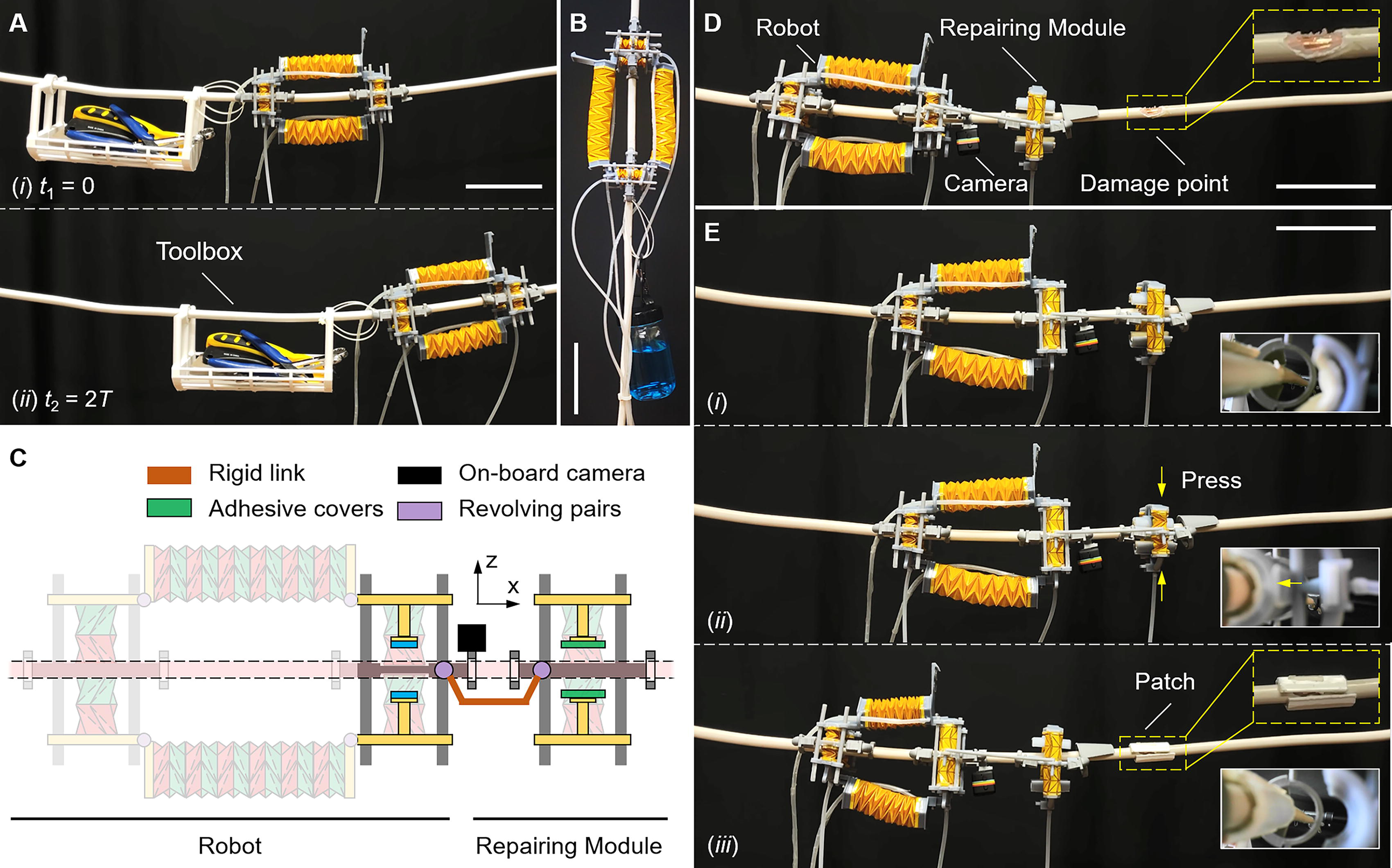
Potential applications of the cable-climbing robot.
Conclusions
This study demonstrates a cable-climbing pneumatic soft robot utilizing origami actuators. The robot shows the merits of high climbing speed, large load capacity, being suitable for climbing cables of various diameters, and being capable of overcoming obstacles (Table 2). The robot is capable of realizing caterpillar-like anchor-crawling locomotion with a maximum moving speed of 0.81 BLs per stride. The cable-climbing robot is composed of one body mechanism and two leg mechanisms, making possible several potentially useful capabilities. First, the body mechanism consisting of two parallel monostable origami actuators has sufficient compliance to adapt to various bends of the cables. Second, the leg mechanism utilizes a bionic gripping design that enables it to climb vertical cables of largely varying diameters, ranging from less than 1–32 mm. Third, the bistable characteristic of the leg mechanism allows the robot to attach itself to cables within a specific diameter range without requiring actuation. Fourth, the main structure of the robot (with its operating fluid being air) is made entirely of insulating materials, including polymers and elastomers, so the robot is not affected by EMI from high-voltage power lines. Fifth, it is lightweight (∼110 g) and only adds minimal load to the cables, without causing any significant deformation or shaking of the cables. Sixth, the robot is modularly designed and can be easily disassembled and reassembled, which enables it to be easily installed on the targeted cable. Furthermore, the robot has a high load capacity (more than 10 times its weight when climbing a 32-mm diameter vertical cable). In addition, different functional modules can be added to the robot, enabling it to perform more complex tasks, such as repairing damaged wires. Lastly, the robot is flexible and therefore harmless to humans, giving it the potential to be used with humans. On the contrary, the current version of the robot also has some limitations. The movements of the robot are currently monitored by an onboard camera, and future work will include installing pressure sensors on the robot’s legs to automatically detect whether the robot’s leg mechanisms are stably gripping or releasing the cables. Additionally, the robot’s performance testing is conducted in a static environment. Future work will examine the robot’s performance in dynamic, real-world application scenarios with external interference. Moreover, the robot is tethered, which significantly restricts its range of motion. To address this, future work includes integrating compressed air and related control units into the robot to achieve an untethered robot design.
Performance Comparison of Different Cable/Rod-Climbing Soft Robots
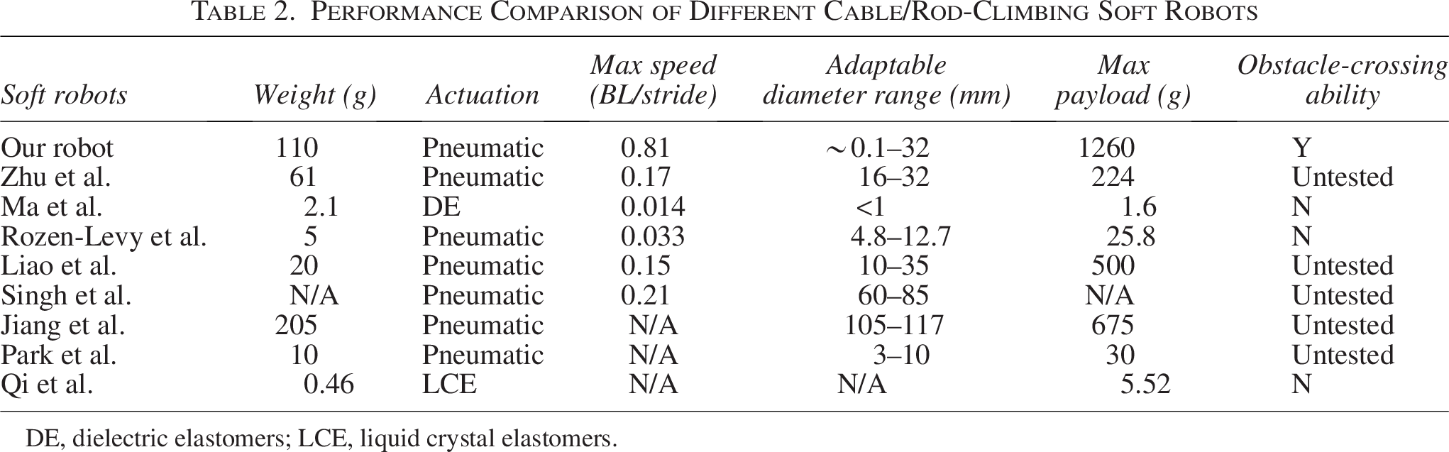
DE, dielectric elastomers; LCE, liquid crystal elastomers.
Authors’ Contributions
J.K. and W.D.W. conceived the study and designed the experiments. J.K. designed and fabricated the robot. J.K. and X.S. performed the experiments with the help of Zifeng Wang. W.D.W. wrote the article and supervised the study.
Footnotes
Acknowledgment
J.K. expresses gratitude to Zifeng Wang for the help received during the experiments.
Author Disclosure Statement
No competing financial interests exist.
Funding Information
This work was supported by the National Research Foundation of Korea (NRF) funded by the Korean government (Ministry of Science and ICT) (No. RS-2023–00210231).