
Abstract
Medical care in the gastrointestinal (GI) tract is a major global issue. Soft actuators are expected to solve associated issues such as poor accessibility and difficult operability within the GI tract. The actuators will be inserted into the body through the mouth or anus with a small diameter, perform various tasks in the GI tract with a large diameter, and finally be removed again. Therefore, deployability and retractivity are common requirements. Variable stiffness is also required to adjust or maintain forces on weak tissues. We proposed the new deployable and stiffness-variable miniature actuator consisting of a shape memory polymer bar and flexible channel part with water circulation, which is useful for medical applications in the GI tract. We established the design method of the actuator based on derived physical models and the fabrication method of prototypes. We evaluated the performances of thermal response, retractive deformation, and variable stiffness and confirmed the validity of the concept through the demonstration of continuous actuation, including deploying, retracting, and stiffness-varying. Furthermore, as a case study, we verified the feasibility of endoscopic submucosal dissection traction using prototypes and artificial materials. In the future, the actuator mechanism and design method may also contribute to the development of other medical tools interacting with delicate tissues in the GI tract.
Keywords
Introduction
In 2018, an estimated 4.8 million people worldwide developed gastrointestinal (GI) cancer, and 3.4 million died from it. 1 In 2020, colorectal cancer caused an estimated 1.9 million cases and 0.9 million deaths worldwide, and these numbers are expected to increase. 2 Medical care and health monitoring in the GI tract are major global issues. On the other hand, various soft actuators have been developed, 3 and their medical applications have also been proposed. 4 Soft microrobotic actuators are expected to solve associated issues such as poor accessibility and difficult operability within the GI tract.
Medical actuators are generally inserted through the mouth or anus with a small diameter of about 20 mm or less, perform various tasks in the GI tract with a large diameter of about 30 mm or more, and are finally removed again through the mouth or anus. Also, the diameter of the GI tract varies greatly depending on the site. Therefore, deployability and retractivity are common requirements for applicable actuators to various missions in the GI tract. The actuators deal with fragile tissues within the deformable GI tract. Surgical procedures such as resections are also carried out carefully and generally take at least several tens of minutes. Therefore, variable stiffness is also required for actuators to adjust the force magnitude depending on the GI deformation state and the surgical progress and to maintain it safely for several minutes.
Various deployable mechanisms have been reported, including methods using thermoset elastomers, 5 rotating flexible crawlers,6,7 moving paddles,8,9 inchworm-like pneumatic structures,10–13 helical pneumatic structures, 14 and self-expanding wire structures. 15 Variable stiffness mechanisms16–18 are being increasingly investigated in the field of soft robotics, including jamming effects,17–19 structural design,17,20,21 electromagnetic rheology fluids,17,22,23 low melting point alloys,17,24,25 and shape memory materials.17,26 Stiffness-variable actuators with shape memory material27–29 have also been reported. In shape memory materials, shape memory polymers (SMPs) can achieve both deployability due to the shape memory effect and variable stiffness due to the phase change. SMPs are also effective due to their light weight, manufacturability, and biosafety. In addition, the modulus variation range of SMPs is expected to be 10–3000 MPa,17,26 which is especially wide among the above variable stiffness mechanisms and is suitable for in vivo uses. Phase change stimuli for SMP devices include water,30,31 light, 32 magnetism,33,34 and temperature.35–43 Especially, temperature-responsive SMP has an advantage due to its easy controllability. Soft actuators using temperature-responsive SMPs include Joule heating35–41 and fluid circulation40–42 as heating or heat exchange methods, and shape memory alloys38,43 and fluid pressure35,40,41 as shape restoration methods. However, there has been no research on miniature soft actuators meeting the requirements of deployability, retractability, and variable stiffness with a size and stroke suitable for medical applications in the GI tracts. Furthermore, it is desirable to select a minimal method and configuration for providing heat exchange and shape restoration functions within the GI tract, which is difficult to reach. Therefore, we proposed a new miniature actuator concept consisting of a temperature-responsive SMP bar and flexible channel part with water circulation. 44 In this concept, the channel performs heat exchange with the SMP bar when water circulates inside the open channel and performs shape restoration due to fluid pressure when water flows into the closed channel. This deployable, variable-stiffness actuator mechanism is promising for medical applications because it can adjust and maintain the force applied to fragile tissues in the deformable GI tract for over tens of minutes.
One possible application of this actuator mechanism is the traction support of endoscopic submucosal dissection (ESD). The main procedure of ESD is a dissection of supportive tissue between the mucosal and muscular layers using an endoscope with an electrosurgical knife. For early GI cancers, ESD allows curative en bloc resection of large GI neoplasms.45,46 ESD is technically demanding, in part because of the lack of traction to elevate the mucosal flap and to expose a dissection plane in the submucosal layer. 46 For traction, the S-O clip, which consists of a spring, rubber strips, and clips, has been reported to be effective in completely resecting large superficial colorectal neoplasms. 45 Endoscopic operations allow the mucosal flap to be attached to the opposite intestinal wall via the S-O clip. The S-O clip can passively generate traction through the restoring force of the spring during ESD procedures. However, such a passive device alone cannot adjust the traction magnitude or direction according to neoplasm resection. As shown in Figure 1, 44 an ESD traction module equipped with the proposed actuator as an active traction tool and a foothold separated from the endoscope may help solve the issues. The module is inserted through an overtube to a specific location and can be fixed to the front of the endoscope by the foothold. After connecting the end of the traction tool and the mucosal flap using the endoscope via a passive traction device, traction can be adjusted by actuating the traction tool.
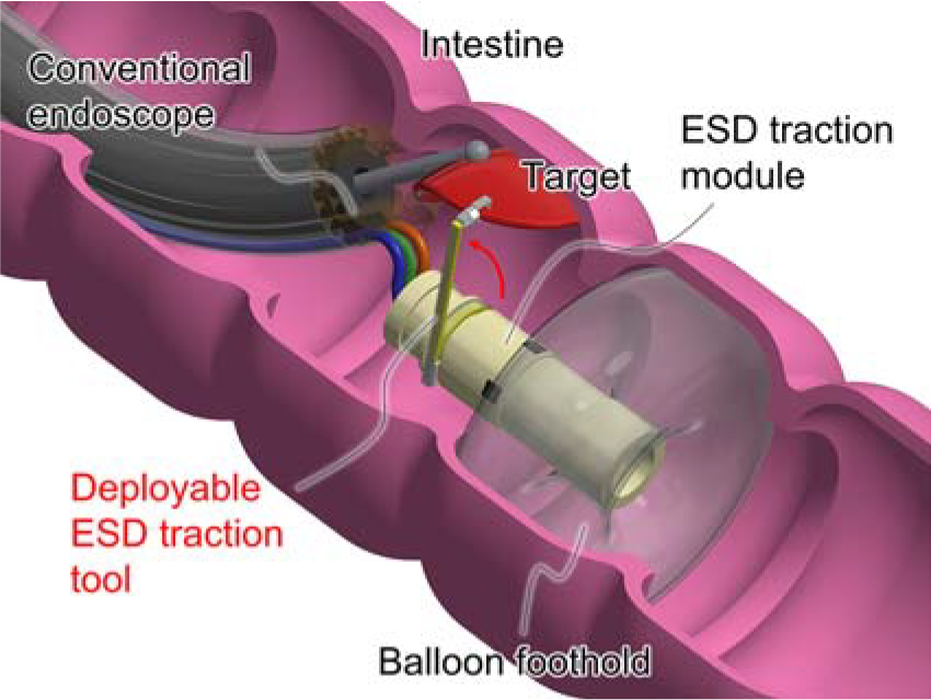
Concept of ESD traction support by another tool separate from conventional endoscope. 44 ESD, endoscopic submucosal dissection.
The previous work 44 reported separate demonstrations of deploying and limited retractive behaviors of the actuator, but its continuous actuation was not achieved mainly due to its incomplete fabrication in the work. In this article, we report on an established design method of the actuator based on physical models, an improved fabrication method of prototypes, and evaluations of its basic performances and continuous actuation, including deploying, retracting, and stiffness-varying behaviors. We also report on a simple verification of ESD traction support using artificial materials as a case study for applications in the GI tract.
Materials and Methods
Concept
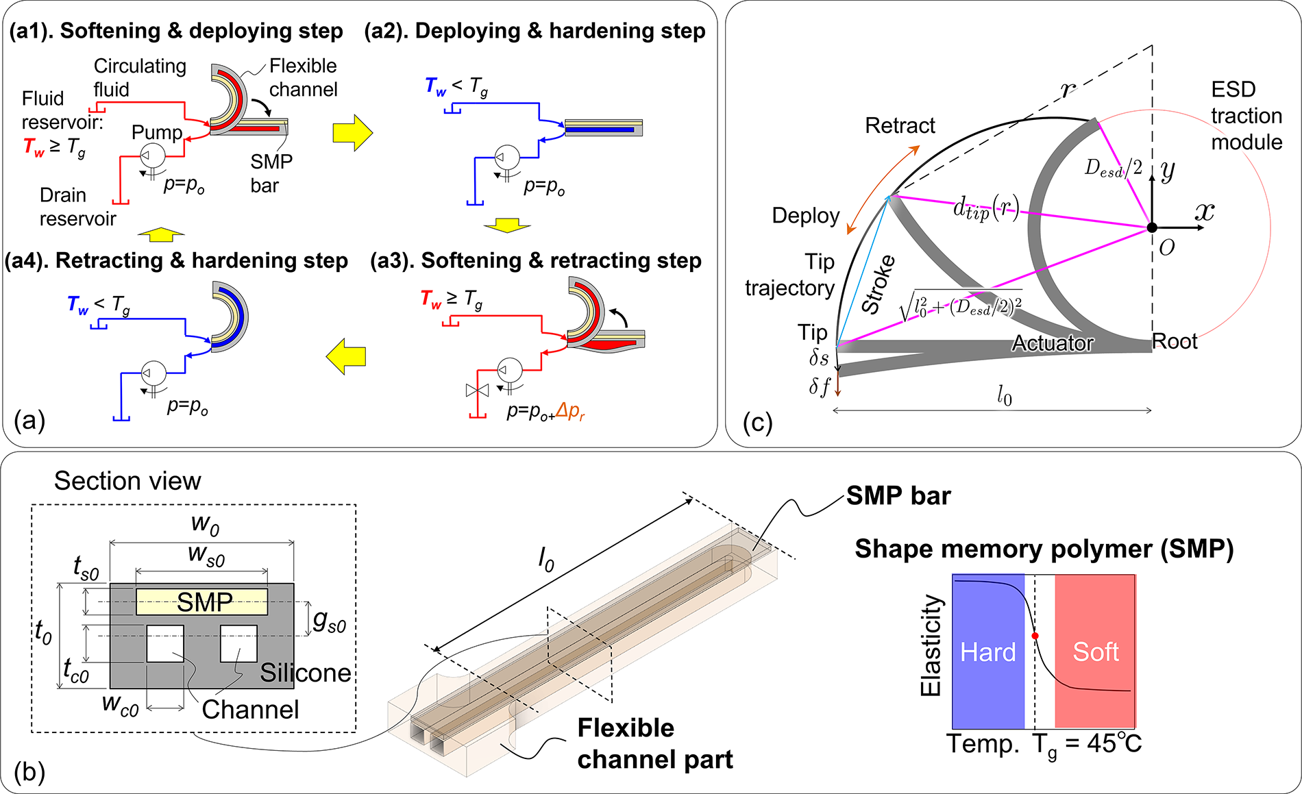
Figure 2a shows the actuator concept and control strategy. It is composed of a flexible fluidic channel part made of silicone rubber and an SMP bar embedded within the channel part.
Actuator concept.
Softening & deploying step
First, when hot water is circulated through the channel by the fluid pressure p = po of an external pump at a temperature Tw above the glass transition temperature Tg of the SMP, the SMP bar softens and changes to the memorized straight state, thereby deploying the actuator (Fig. 2a1).
Deploying & hardening step
The SMP bar then keeps the actuator in the hard-deploying state by circulating cold water with Tw < Tg (Fig. 2a2).
Softening & retracting step
Next, hot water flowing to the channel with the valve closed makes the SMP soften, and the actuator retracts under the additive fluid pressure p = po + Δpr (Fig. 2a3).
Retracting & hardening step
The SMP can again keep the actuator in the hard-retracting state by circulating cold water again (Fig. 2a4).
While the SMP bar contributes to variable stiffness, the flexible channel with water makes both heat exchange and pressure deformation possible, and water as a working fluid contributes to effective heat transfer and biosafety.
Configuration and parameters
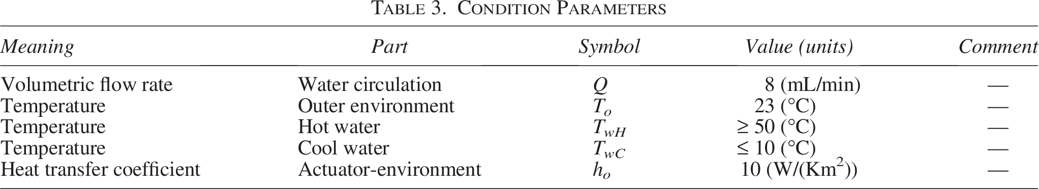
The configuration and design of the actuator are shown in Figure 2b. As summarized in Table 1, dimension parameters were decided considering deployable requirements and several performances by theoretical models described later. Physical, condition, and estimated parameters are also summarized in Tables 2–4, respectively. An actuator was designed with external dimensions l0 = 20 mm, w0 = 5.0 mm, and t0 = 2.5 mm. The cross-sectional dimensions of the U-shaped channel inside the actuator are wc0 = 1.0 mm and tc0 = 0.5 mm. For temperature control of the SMP material, the required hot water temperature needs to be higher than body temperature with 36–37°C, but too high a temperature is dangerous to avoid the risk of unexpected burn damage. However, even if hot water leaks accidentally into the GI tract, its temperature of around 60°C is acceptable, based on the optimized temperature of hot beverages that takes into account the risk of burn damage.47,48 Therefore, we assumed the SMP material with Tg = 45°C for biosafety. The cross-sectional dimensions of the SMP bar are ws0 = 2.4 mm and ts0 = 0.8 mm, and its length is regarded as the same as the channel length. The half-thickness position, t0/2, is defined as the actuator neutral axis. The SMP bar is positioned at a gap gs0 = 0.85 mm relative to the actuator neutral axis. During the softening and retracting step, the gap gs0 and the constant arc-length of the SMP bar allow the expansion of the flexible channel to be converted into actuator bending.
Dimension Parameters
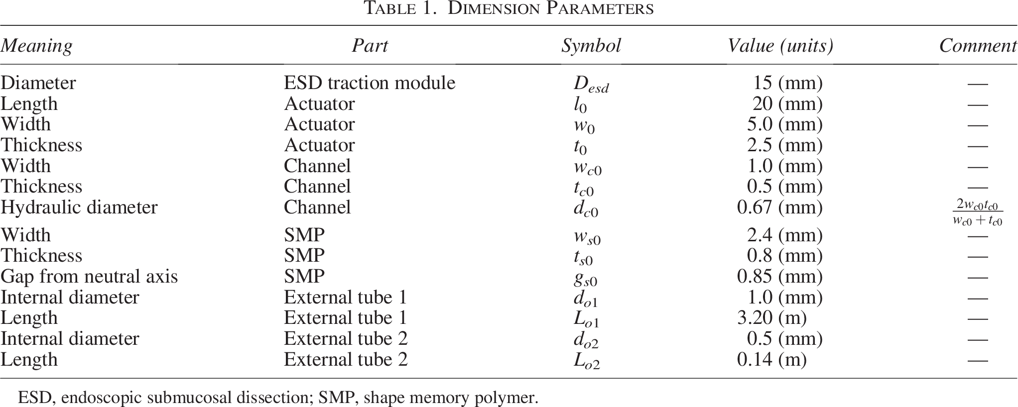
ESD, endoscopic submucosal dissection; SMP, shape memory polymer.
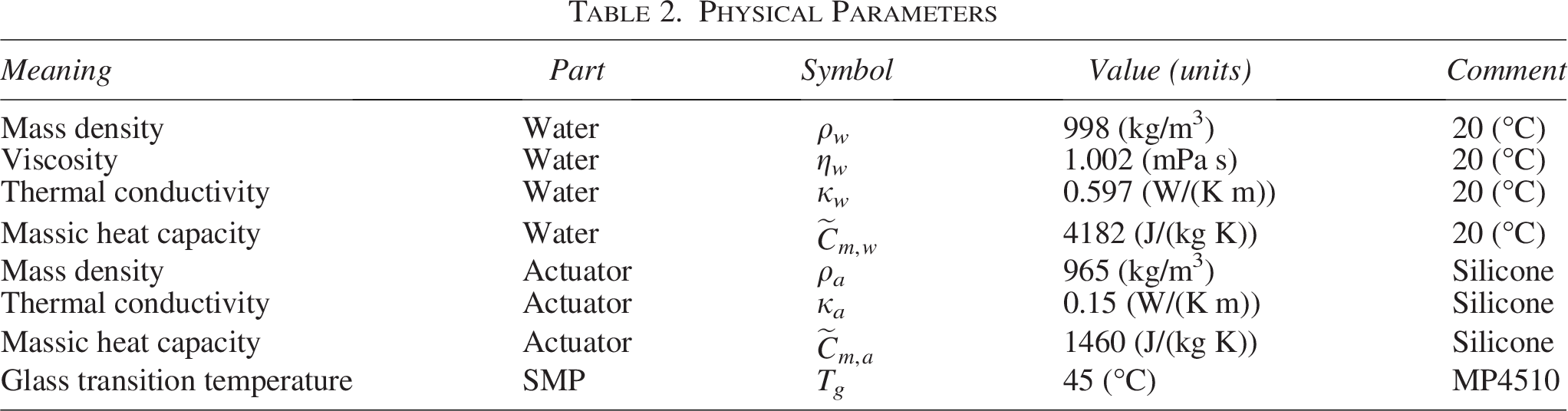
Physical Parameters
Condition Parameters
Estimated Parameters
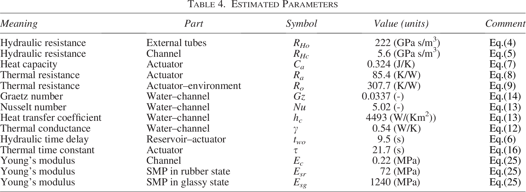
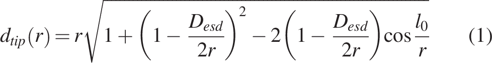
Figure 2c shows the geometrical configuration and parameters of actuator deformation. The xy plane is set at a cross-section perpendicular to the central axis of the cylindrical ESD traction module with diameter Desd = 15 mm. The origin of the xy plane is set on the central axis of the module. The root of the straight-shaped actuator in the deploying state is fixed to be tangent to the cross-sectional circle of the module. The neutral axis of the actuator is assumed to deform uniformly with one curvature. When the actuator deforms with curvature radius r, the actuator tip distance dtip from the module center is described as follows (Please see Supplementary Note N1 for the derivation):
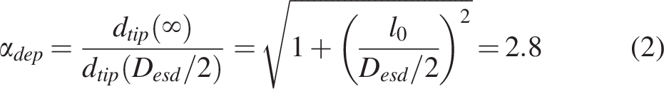
Deploying rate α
dep
is defined and estimated as follows:
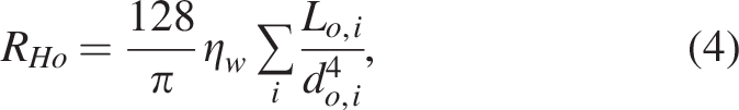
Hydraulic model
Figure 3a shows the lumped circuit model of water circulation with flow rate Q. Assuming laminar flow in the water circulation circuit, the fluid pressure drop can be neglected due to changes in cross-sectional diameter and flow direction of all channels. Therefore, the pressure po by the pump for the circulation can be written as
49
:

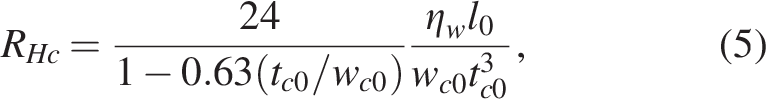
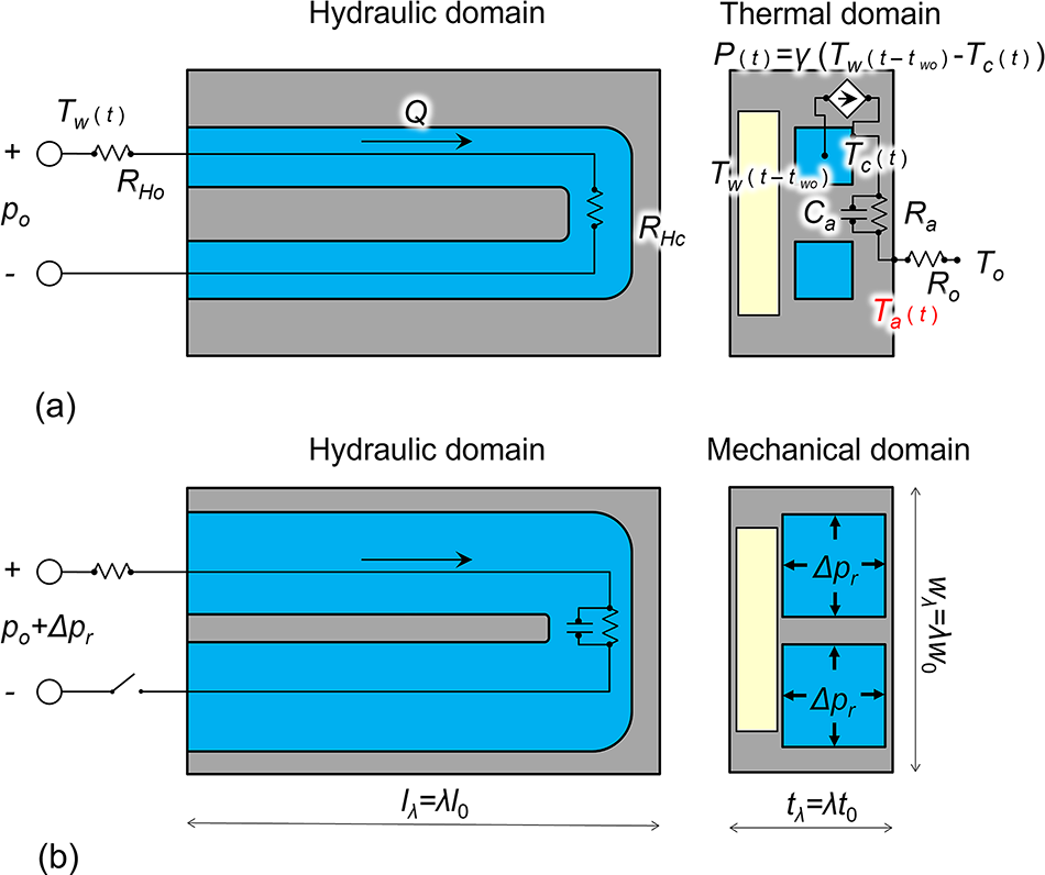
Theoretical model with parameters.
The hydraulic time delay two from the hot- or cold-water reservoir to the actuator, assuming that the water flows half the length of the external tubes, is defined as follows:
Thermal model
As shown in Figure 3a, we derive a lumped thermal model
50
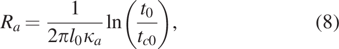
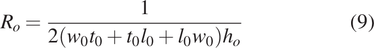
for thermal design of the actuator. For simplicity, we assume that the temperature distribution is uniform along the channel flow direction and that the thermal parameters of the SMP are the same as those of the channel part. The heat capacity Ca and thermal resistance Ra within the actuator, and the thermal resistance Ro between the actuator’s outer surface and the environment, are defined as:

The time response of the difference between the channel surface temperature Tc(t) and the outer surface temperature Ta(t) in the actuator is described as follows:
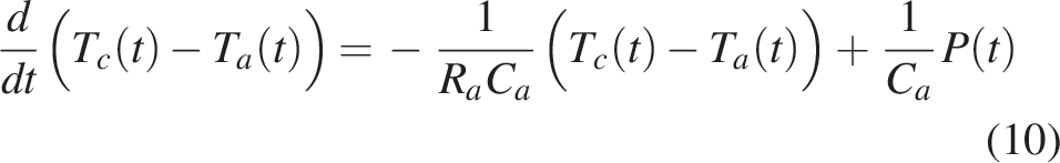
Ta(t) is assumed to be approximately the same as the SMP temperature. The total heat current P(t) from the circulating water at temperature Tw(t − two) to the channel surface is given by:
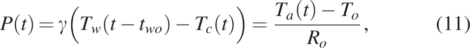

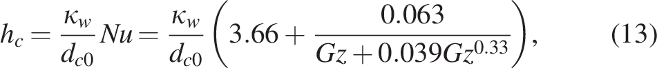
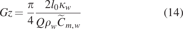
γ means the thermal conductance between the channel surface and the circulating water. Its heat transfer coefficient hc can be expressed as follows using the approximation for the Nusselt number Nu obtained from the Graetz problem51–53
:
Solving Eqs (10) and (11), Ta(t) can be derived as a first-order system with time constant τ and input time delay two as follows:
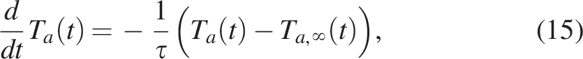
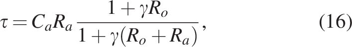
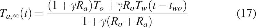
τ is estimated as 21.7 s using the parameters in Tables 1–4. It is expected that 90% convergence of Ta(t) requires about 2.3τ = 50 s other than two.
Retractive deformation model
As shown in Figure 3b, the deformation model for the retracting behavior can be derived based on the rubber elasticity theory.
54
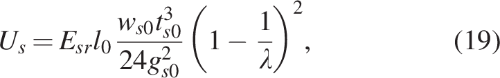
For simplicity, it is assumed that the additive fluid pressure Δpr in the channel causes the channel part to expand isotropically, the length is constrained by the SMP bar in its rubber state, and the entire actuator bends. Assuming a deformation factor λ ≥ 1, the outer dimensions of the channel part when isotropically deformed can be defined as lλ = λ l0, wλ = λ w0, tλ = λ t0. Based on the assumption that the volume of the rubber volume element is constant, the free energies Uc, Us of the expanded channel part and the bent SMP bar, and the work W due to the fluid pressure Δpr are described as follows:


Total free energy U(λ) for the actuator satisfies:

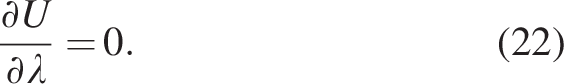
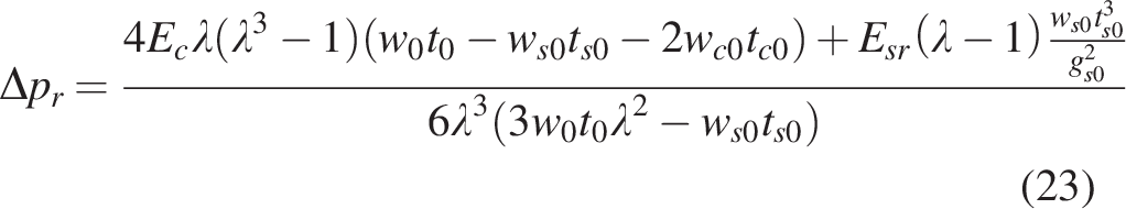
From the equilibrium state Eq. (22), the additive fluid pressure Δpr can be derived as follows:
The curvature radius r of the actuator neutral axis is also described as follows:
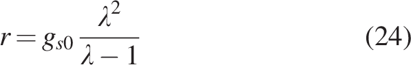
Theoretical tip distance dtip can be roughly estimated due to fluid pressure Δpr during the softening and retracting step by using Eqs (1), (23), (24) and parameters in Tables 1–4. It is expected that dtip of about 10 mm requires Δpr of about 50 kPa.
Variable stiffness model
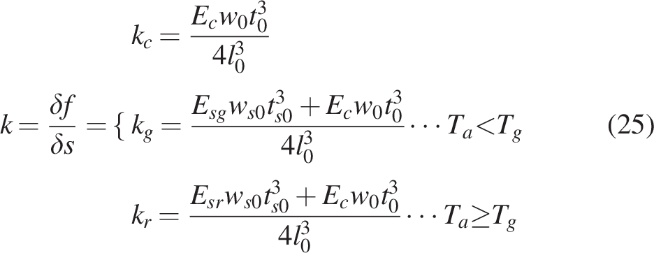
As shown in Figure 2c, it is assumed that a force δf causes a tangential displacement δs at the tip of the straight-shaped actuator. For simplicity, the actuator shape ignoring channel regions is assumed. From the bending energies of the channel part and the SMP bar, actuator stiffness can be expressed as follows:
Fabrication process
Figure 4a shows the fabrication process of actuator prototypes. First, the SMP bars are made by curing liquid SMP (MP4510, SMP Technologies, Inc.), pressing the hardened SMP block under heat to remove air bubbles using a small heat press machine (H300-10D, AS ONE Corp.), and then dicing it using a dicing saw (DAD3650, DISCO Co.). Next, a section of the flexible part with channel grooves and the SMP bar embedded in it is fabricated by molding liquid silicone (Ecoflex 00–50, Smooth-On, Inc.). The channel grooves are filled with paraffin as a sacrificial material, and then a lid layer is fabricated by molding to cover the top of the grooves. Finally, the paraffin is dissolved by heating, and the actuator prototype is obtained after cleaning. The detailed design of the molds is shown in Supplementary Figure S1. This process does not use any bonding methods as in our previous work, 44 ensuring strength between the lid and the channel layers.
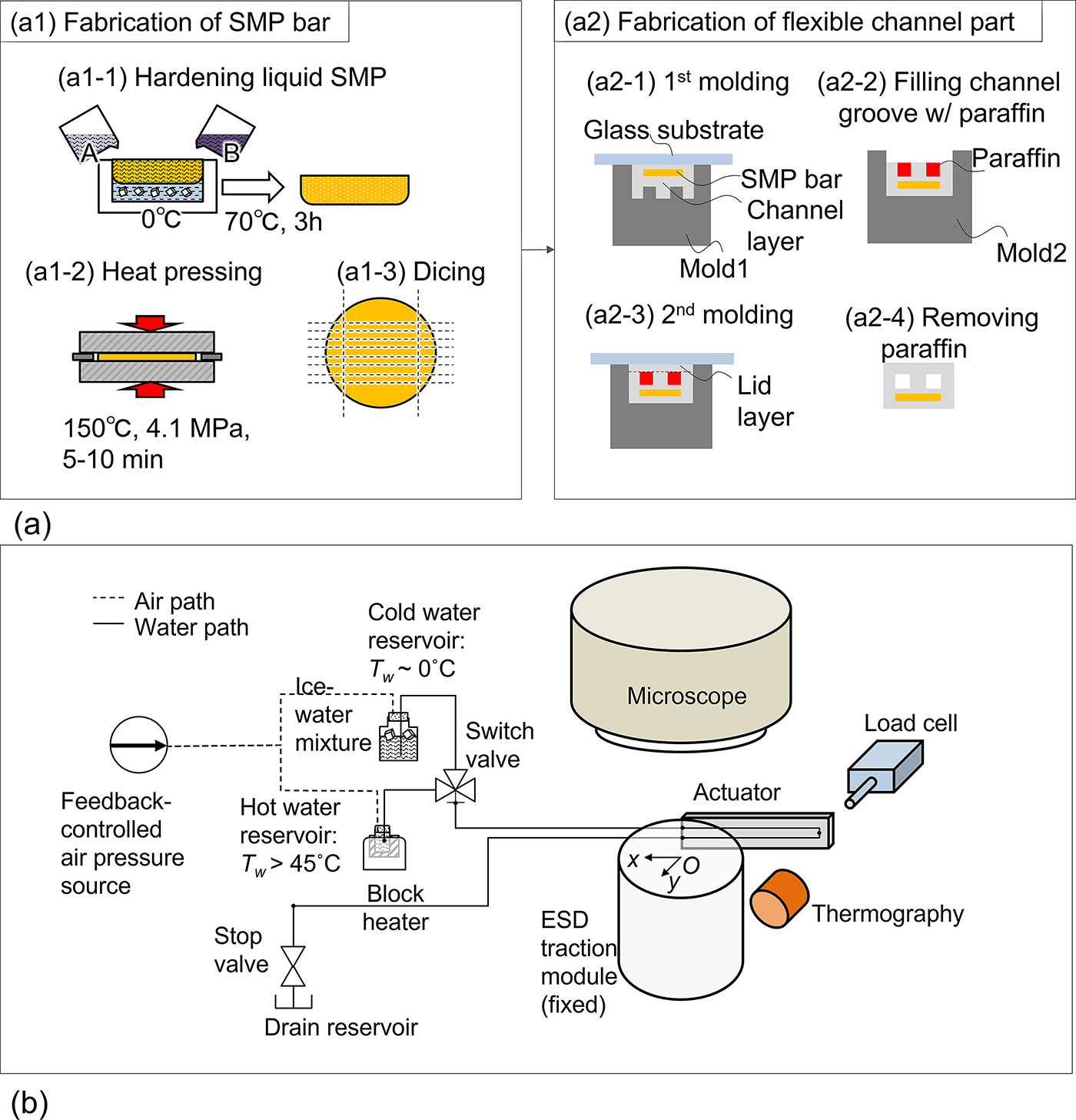
Schematic diagrams of fabrication process and experimental setup.
Experimental setup
Figure 4b shows the experimental setup for evaluating the actuator prototype. A fabricated ESD traction module was fixed with its center axis aligned along with the vertical axis and its end face fixed to a flat surface. Using a microscope (LuxOR E71 Q-Vue, Alcon, Inc.) and camera (acA1300-200uc, Basler AG) above the module, the deformation of the actuator prototype in the xy plane can be observed and recorded. The actuator surface temperature Ta was simultaneously measured non-contact by a thermography camera (PI640i, Optris GmbH Co. KG). The temperature at the root of the actuator was used (Supplementary Fig. S2). A water circulation system, including a pressure pump (MFCS-FLEX 8C, Fluigent Co., Ltd.), switch or stop valves, and hot- and cold-water reservoirs, was connected to the inlet and outlet ports of the actuator (Supplementary Fig. S3). The pumps and valves were operated manually. When variable stiffness was evaluated, a load cell (LTS-50GA, Kyowa Electronic Instruments Co., Ltd.) was also used in the xy plane (Supplementary Fig. S4).
Results
Prototype
Actuator prototypes were successfully fabricated according to the design in Table 1 and the process in Figure 4a and Supplementary Figure S5. Figure 5a,b shows a fabricated prototype and the cross-sectional view obtained by slicing it, respectively. Figure 5c shows a prototype of the ESD traction module with the actuator prototype assembled according to the tentative design (Supplementary Fig. S6). Tentatively, the main components of the module were printed using UV-curable acrylate-based materials (Clear Resin, Formlabs Inc.) and a UV-curable 3 D printer (Form3, Formlabs Inc.). To ensure ventilation within the intestine, a through hole is provided near the central axis of the module. A disposable balloon (BS-4, Fujifilm Corporation) for double-balloon endoscopes can be fixed to the front of the module and can act as a foothold to the intestinal wall. A hook part is also fixed at the tip of the actuator, and one end of the S-O clip (Zeon Medical Inc.) can connect to the hook part.

Prototypes.
Thermal response
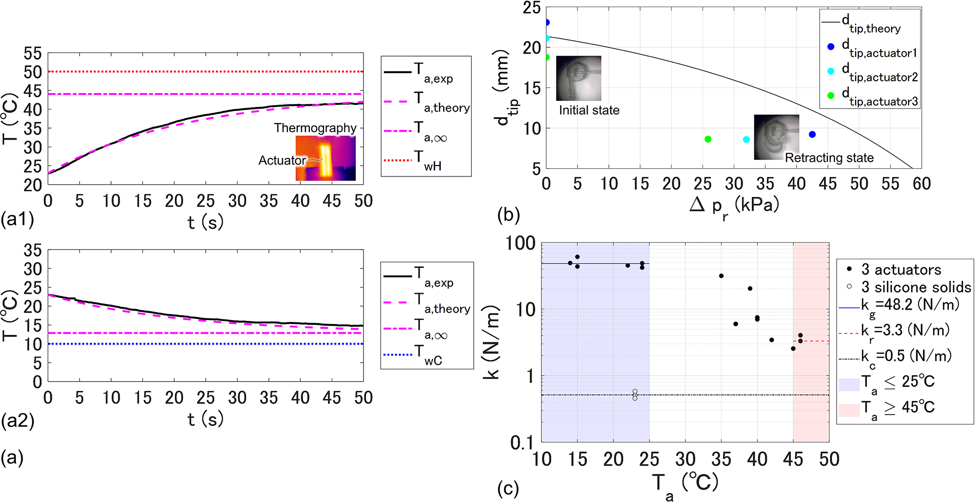
We evaluated the thermal responses of the actuator experimentally and theoretically. Figure 6a shows experimental responses of the actuator surface temperature Ta in heating (Fig. 6a1) and cooling (Fig. 6a2) cases by the thermography camera. Theoretical curves are also shown in Figure 6a estimated by using Eqs (15), (16), (17), and parameters in Tables 1–4. Each graph also includes the convergence value Ta,∞ and the water temperature TwH or TwC. The hydraulic time delay two was not evaluated in the cases since t = 0 was set when Ta started to change. In both cases, the experimental results are in close agreement with the theoretical curves.
Evaluations of basic performances.
Retractive deformation
We evaluated the retractive deformation of the actuator due to fluid pressure. The motion is used during the softening & retracting step. Figure 6b shows theoretical estimates and experimental results of tip distance dtip due to fluid pressure Δpr. The estimates were calculated by using Eqs (1), (23), (24) and parameters in Tables 1–4. The experimental results before and after the deformation of three actuators are also shown in Figure 6b. Errors were confirmed between the theoretical curve and the experimental results. The causes of the errors are considered to be that the thin parts of the actuator expanded and deformed and that the deformation in the longitudinal direction of the actuator was not uniform. However, since the theoretical values were slightly larger than the experimental values and were in the same order of magnitude, this analytical model is available for estimating the required pressure at the actuator design stage.
Variable stiffness
We evaluated the variable stiffness of the actuator. Figure 6c shows experimental results of actuator stiffness k according to its surface temperature Ta. Based on the configuration in Figure 2c, several forces δf were measured quasi-statically by the load cell using three actuator prototypes and three silicone solid objects in cases of displacements δs ≤ 2 mm. Each k was estimated by the linear slope from those values.
kg = 48.2 N/m was obtained by averaging experimental values under Ta ≤ 25°C, so δf of approximately 100 mN can be generated with δs = 2 mm in the hardening steps. The stiffness of the S-O clip is estimated to be approximately 3.1 N/m, 45 and the restoring force in the intestine is expected to be around 100 mN. Therefore, the kg value is considered acceptable for ESD traction.
kr = 3.3 N/m was obtained under Ta ≥ 45°C, which was less than one-tenth of kg. In addition, kc = 0.5 N/m was obtained using silicone solid objects. Young’s modulus Esg = 1.24 GPa, Esr = 72 MPa, and Ec = 220 kPa are estimated from Eq. (25), those k values, and dimension parameters in Table 1.
Continuous actuation
We conducted experiments to verify the continuous actuation, according to the control strategy in Figure 2a. The result is shown in Supplementary Movie. Figure 7a–e indicates snapshots from the recorded movie of the optical microscope, input pressure p response, actuator surface temperature Ta response, actuator tip trajectory identified from the movie using “OpenCV,” and actuator tip distance dtip response identified from the trajectory, respectively.
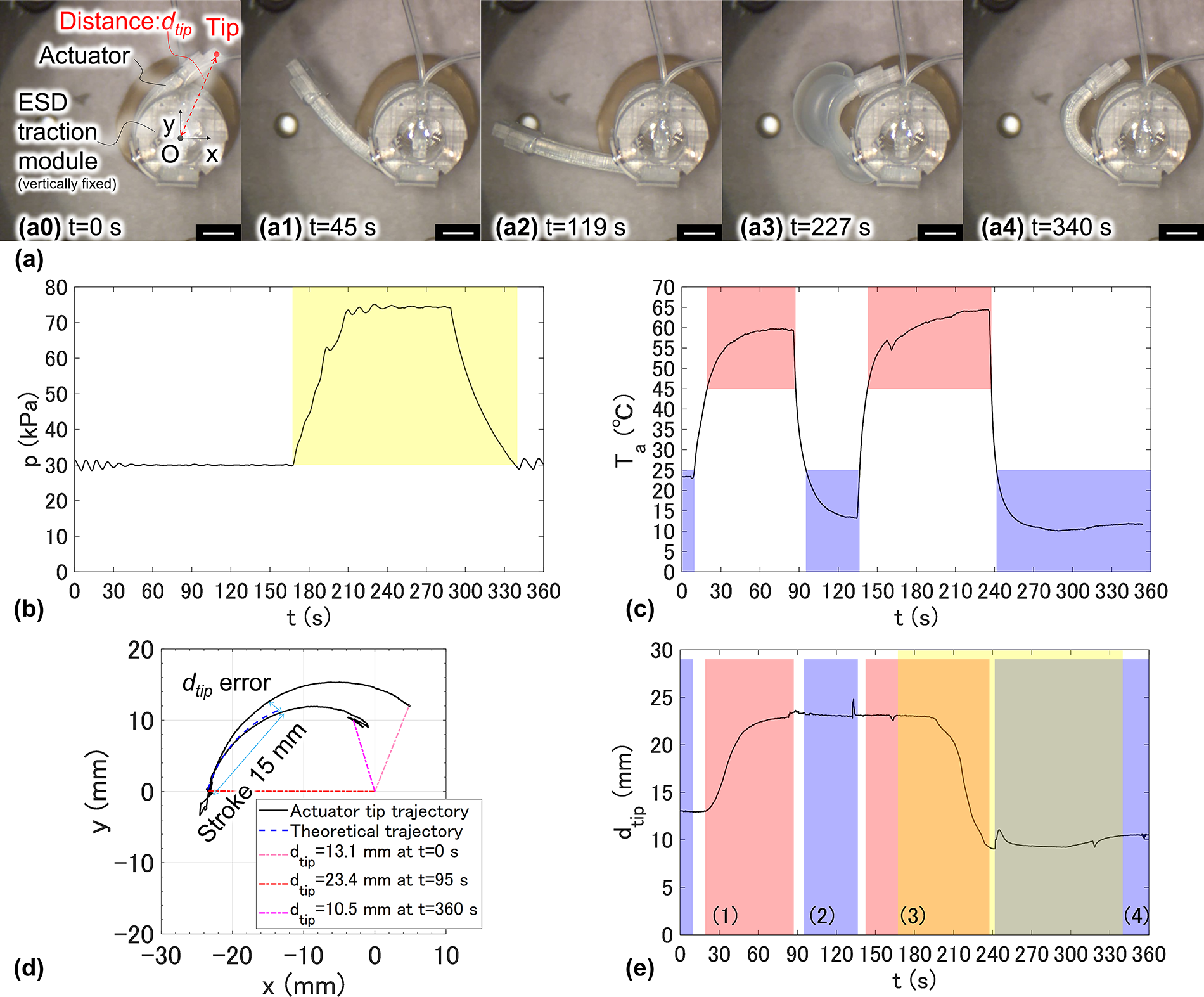
Demonstration of continuous actuation.
Softening & deploying step
The hot water circulation started with p = po = 30 kPa and Q = 8 mL/min at t = 0, and Ta began to rise from room temperature of 23°C at t = 10 s, which was almost consistent with the hydraulic time delay two. Just when Ta reached 45°C, the actuator became softened and began to deploy from the initial retracting state to the memorized straight-shaped state. After that, dtip was almost synchronized with Ta and nearly converged to 23 mm in 2.3τ = 50 s from t = 10 s.
Deploying & hardening step
The hot water circulation was then switched to cold water circulation, Ta dropped below 25°C, and the actuator hardened at t = 95 s.
Softening & retracting step
The cooling was then switched back to the heating, and Ta reached 45°C or higher, causing the actuator to soften again. Next, the water circulation path was closed, and the pressure p was increased in a ramp manner from po = 30 kPa to po +Δpr = 75 kPa. Then the actuator started to retract, and dtip reached about 10 mm, which is close to the performance estimates in Figure 6b. Although the lid layer expansion was larger than expected, the retractive deformation model is sufficient for estimating the deformation of the actuator neutral axis.
Retracting & hardening step
The cooling circulation was restarted. The actuator then stopped expanding, Δpr was added to the circulation, and the Q increased to 20 mL/min. Ta quickly reached below 25°C and the actuator hardened in the retracting state with dtip = 10.5 mm. Finally, Q returned to 8 mL/min due to Δpr = 0.
The continuous actuations of the other two actuators were also acquired, and Supplementary Figure S7 shows those identified tip trajectories. From the above, the continuous actuation was succeeded.
Tip trajectory accuracy
As shown in Figure 7d, the trajectory of the actuator tip has errors compared to the theoretical trajectory calculated by Eq. (1). Figure 8 shows dtip errors between experimental and theoretical trajectories for three actuators in Figure 7 and Supplementary Figure S7 within 15 mm of tip stroke from the deploying state.
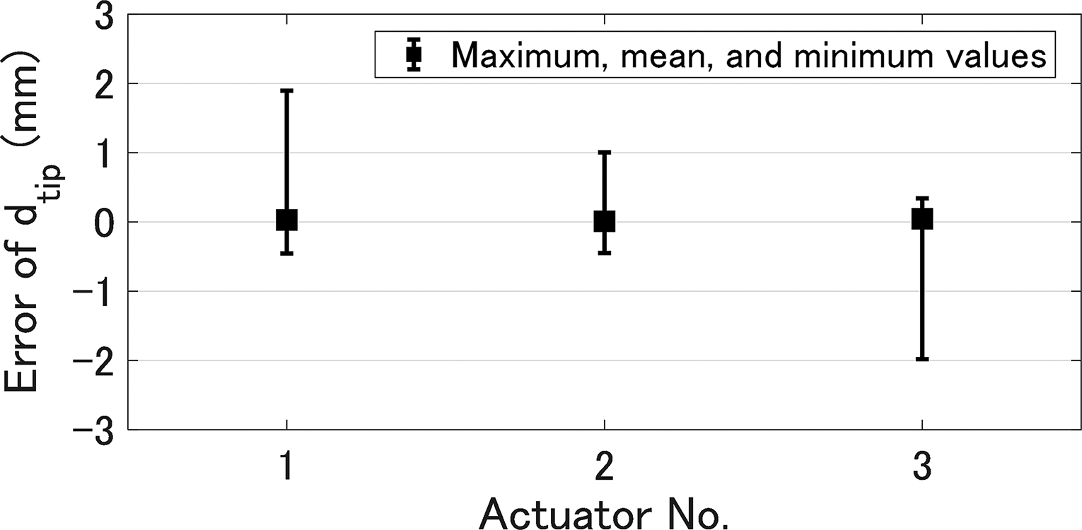
dtip errors between experimental and theoretical trajectories for three actuators within 15 mm of tip stroke from the deploying state. Actuator No. 1 was identified from the data in Figure 7d, and actuator No. 2 and 3 were identified from the data in Supplementary Figure S7.
Assuming that a tumor of approximately 15 mm is to be resected, the trajectory error is expected to be approximately ±2 mm from the results.
ESD traction
We verified the feasibility of ESD traction using a prototype of the ESD traction module and artificial materials. The result is shown in the supplementary movie. Figure 9 shows the snapshots from the movie. First, the module was fixed inside the hydrogel intestine model using the inflated balloon. For easy observation, a mucosa model (VTT-MCS, KOTOBUKI Medical Inc.) was placed on the outside of the intestine model. The actuator tip in the deploying state was connected to the mucosal flap of the mucosa model via an S-O clip (Fig. 9a). Next, the actuator pulled the flap through the softening and retracting step (Fig. 9b). Finally, the actuator hardened in that state (Fig. 9c). Although the traction was not sufficient in the final state because of the initial short distance between the actuator tip and the flap, this result suggests that this actuator can be used for ESD traction.
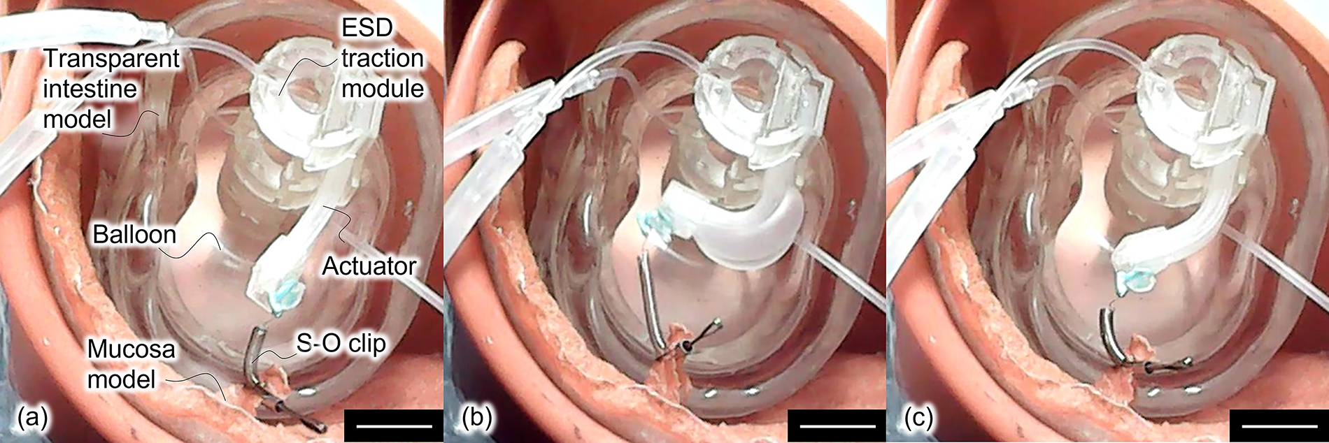
Feasibility test of ESD traction.
Discussion
From the experimental results, it was confirmed that the derived models are valid for the design of this actuator. Although the current design is considered to be effective for ESD traction, it is not optimized, so redesign using these models may improve its performances. These models are also useful in designing smaller or larger actuators for other applications and model-based control systems55,56 for the actuators.
Although the continuous actuation was successful, several issues remained. From the trajectory in Figure 7, both the deployment and the retraction were not sufficient. These are mainly caused by insufficient deformations near the root and tip of the actuator, so could be improved by optimizing the hook part located at the tip and the fixed part near the root. The deploying motion with heating and cooling requires at most 2(two + 2.3τ) ≃ 120 s theoretically and experimentally. The retracting motion took a longer response, but if the operations could be automated and optimized, the response should be reduced to the same as the deploying response. The actuator response is relatively long for general applications but acceptable for prudent medical procedures such as ESD, which takes tens of minutes at least. Furthermore, by increasing the flow rate Q, two can be made significantly smaller. Thermal response might be enhanced by bang-bang input control with temporarily higher (or lower) water temperature within the limits of biosafety. Tip positioning has not yet been achieved, but its accuracy is expected to be at least ±2 mm from Figure 8.
A comprehensive interpretation of the scalability of this actuator’s dimensions is beyond the scope of this article. But some insights can be acquired from established theoretical models. First, larger actuators are not suitable for use in the GI tract and require consideration of the effects of gravity. Next, we simply assume that all dimensions shown in Table 1 are isotropically reduced by a factor of α < 1. From Eqs (7), (16), and (25), thermal time constant τ and stiffness k will be α times smaller, and from Eq. (5), hydraulic resistance RHc will be 1/α3 times larger. Therefore, it is expected that smaller actuators will need to be redesigned to meet all performance requirements and applications.
Conclusion
In this research, we theoretically and experimentally demonstrated the actuation of the deployable and stiffness-variable miniature actuator consisting of an SMP bar and flexible channel part with water circulation, which is useful for medical applications in the GI tract. First, we established the design method of the actuator based on derived physical models and the fabrication method of prototypes. Using fabricated prototypes, we evaluated the performances of thermal response, retractive deformation, and variable stiffness, and confirmed the validity of the concept through the demonstration of continuous actuation, including deploying, retracting, and stiffness-varying. In addition, using the prototypes and artificial materials, we confirmed the feasibility of ESD traction as one of the medical applications.
Next issues are establishment of a tip position control system, redesign of the actuator to maximize performances by using the derived models, and verification of its medical validity by using an artificial intestine model or an animal with the optimized actuator. In the future, the actuator mechanism and design method used in this research may also contribute to the development of other medical tools interacting with delicate tissues in the GI tract, such as forceps, footholds, crawlers, and so on.
Footnotes
Acknowledgment
The authors thank Dr. Hisataka Maruyama of Nagoya University for providing the hydrogel intestine models.
Author Disclosure Statement
No competing financial interests exist.
Funding Information
This research was supported by JST Moonshot R&D-MILLENNIA Program under Grant JPMJMS2214-01.
Supplemental Material
Supplemental Material
References
Supplementary Material
Please find the following supplemental material available below.
For Open Access articles published under a Creative Commons License, all supplemental material carries the same license as the article it is associated with.
For non-Open Access articles published, all supplemental material carries a non-exclusive license, and permission requests for re-use of supplemental material or any part of supplemental material shall be sent directly to the copyright owner as specified in the copyright notice associated with the article.