
Abstract
This article presents an integrated fabrication and simulation framework for a cable pneumatic soft robot system capable of dexterous motions and complex functions. These cable pneumatic robots can harness pneumatic actuation for large shape morphing and utilize cable actuation for superior controllability. We first created a novel and low-cost fabrication method to build the proposed robots, including the soft robot structures and the controller hardware. In parallel, we developed a lumped parameter model to simulate the complex behaviors of cable pneumatic robots. This simulation platform is computationally more efficient than conventional finite element methods because it uses specially derived lumped elements with sparser nodes and less degrees-of-freedom. In addition, we use experiments to show that the model can accurately capture the bending stiffness and the actuation angle of the cable pneumatic robots. Finally, demonstration examples are presented to highlight the capabilities of the proposed robots and the versatility of the simulation. Realistic physical prototypes are presented to show that these robots can execute adaptive grasping motions and handle sophisticated tasks. Computational examples are presented to show that the proposed model can achieve close-to-real-time simulation. More significantly, we can implement cosimulation of cable pneumatic robots and the inverse kinematics of UR5e cobots by combining the proposed lumped parameter model with existing robotic simulators. Such capabilities enable the proposed simulation to have wide applications for different soft robotic systems.
Introduction
This work introduces a new class of cable pneumatic soft robots that combine two distinct actuation strategies: cable-driven and pneumatic actuation. Figure 1 shows a schematic illustration of the proposed robots, where pneumatic actuation enables the robot to deploy from a compact configuration to its functioning state, while cable-driven actuation provides directional bending and gripping motions. These robots enable coordinated behaviors that cannot be accomplished with traditional cable-driven robots or pneumatic robots, creating a new soft robot platform to achieve complex tasks for practical applications. The Supplementary Video provides a highlight of this work.
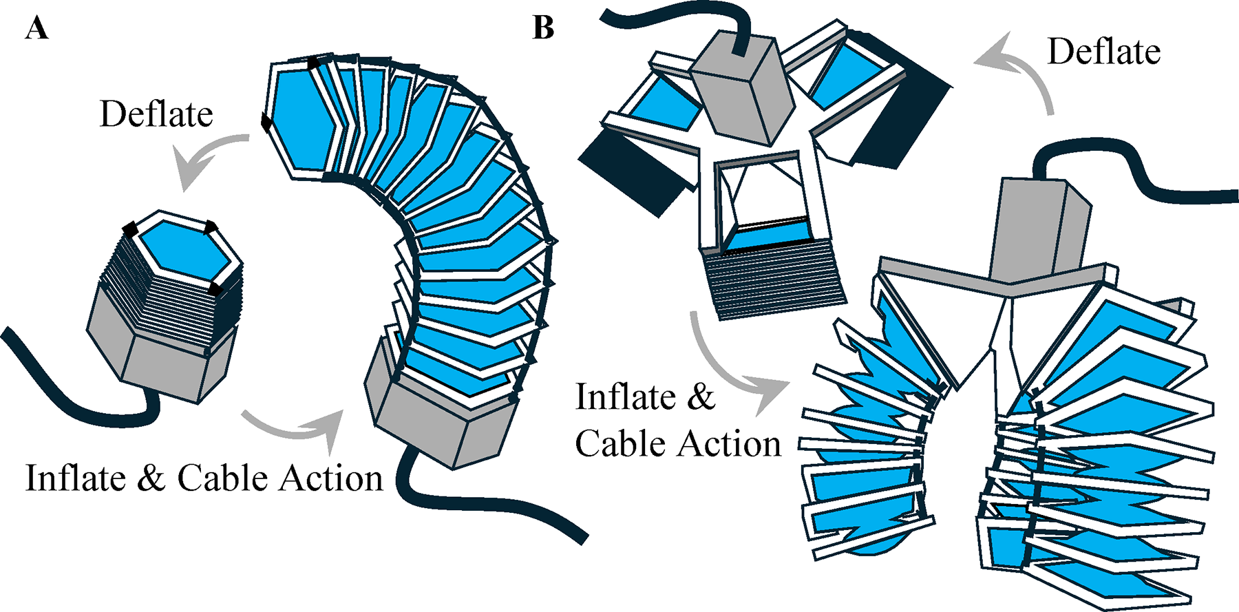
Cable pneumatic soft robots.
Over the past decades, many soft robotic systems have been developed for applications to handle delicate and sensitive items.1–3 The compliant interfaces of soft robots enable safe interactions with human users and biological samples, supporting diverse medical applications.4,5 To meet the functional demands of these soft robotic applications, researchers have developed a wide variety of actuation mechanisms, including pneumatic actuators, 6 cable-driven robots, 3 shape memory materials, 7 piezoelectric actuators, 8 and electrothermal actuator 9 . Among these different systems, pneumatic and cable-driven systems have attracted attention due to their advantages in deformation properties and motion control abilities.
Pneumatic actuators feature simple structures, large deformation, and ease of fabrication. These actuators can generate diverse motions, including bending,10–12 extension,13–15 and torsion. 16 More complex motion paths can be achieved through multistable chamber designs actuated by a single pressure source. 17 Pneumatic actuation has also been utilized to perform stochastic grasping through an entanglement-based strategy. 18
While pneumatic actuators offer diverse and complex deformation behaviors, cable-driven systems provide complementary advantages in precise position control, rapid response, and high force transmission. These systems are typically underactuated and thus require only a small number of motors to achieve a wide range of motions.19,20 When combined with rigid links, cable-driven systems can form tensegrity robots capable of reconfiguration and rich functionality.21–23 Such systems have also been used for applications such as emergency shelters 24 and space rovers. 25
In addition, recent studies have explored a variety of hybrid systems that combine pneumatic actuation with cable-driven mechanisms. For example, combining a pneumatic origami chamber and tendon-driven actuation can achieve multimodal motion and stiffness modulation.26–28 While these hybrid systems demonstrate impressive capabilities in shape control, actuation, and deployment, their constructions are based on pneumatic origami cores with restricted kinematic motions and less flexibility. As will be shown, this work builds a less restrictive pneumatic core formulation to achieve higher extension and bending dexterity. Furthermore, these existing works have not developed a unified and computationally efficient simulation framework to capture the coupled mechanics between pneumatic inflation, cable tension, and structural deformation.
The structure of this article is as follows: The Design and Fabrication section introduces how to fabricate the cable pneumatic robots and how to operate them using an Arduino microcontroller. The Lumped Parameter Simulation section demonstrates a lumped parameter model capable of rapidly simulating the behaviors of the proposed robots. The Model Verification with Experiments section further compares the simulation results with experiments to demonstrate the accuracy of the proposed modeling approach. The Demonstration Examples section provides demonstration examples that highlight the advanced capabilities of the proposed robots and the computational efficiency of the proposed modeling approach.
Design and Fabrication
Fabrication of pneumatic core
Figure 2A illustrates the fabrication process for the proposed cable pneumatic robots. The air chamber is fabricated using plastic films. First, films of identical sizes are cut and paired together. Each pair is aligned and fused at the center region using a soldering iron set to 150°C or 310°F. Next, a hole is pierced through the fused region using a pin punch. After preparing multiple films, we seal the perimeter between adjacent films using a heat sealer. This process builds multiple airtight units connected through the punch holes. To reduce buckling of the thin films, rigid frames are 3D-printed and attached to the perimeter of the air chamber using metal pins. Finally, cables and tubes are attached to the pneumatic core to finish the fabrication.
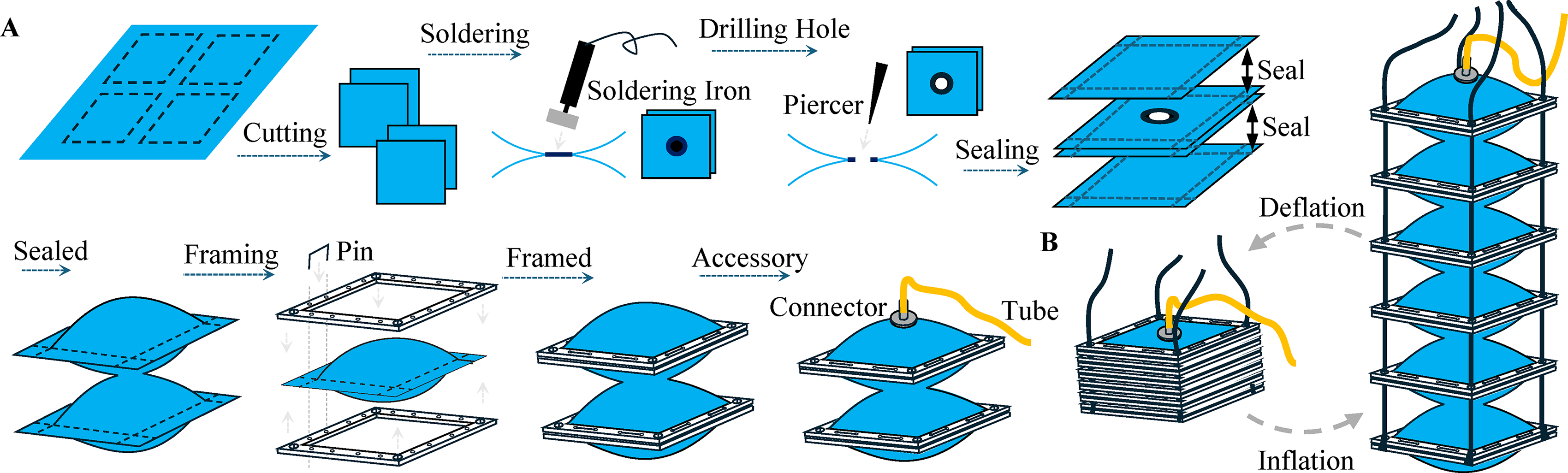
Figure 2B illustrates the working principle of the pneumatic core. Pumping air into the pneumatic core extends the structure to its functioning state. In this inflated configuration, applying tension to selected cables can bend the robot toward desired directions. Deflating the pneumatic core turns the robot into a compact state for convenient storage and transportation.
Pressure regulation and cable actuation
We use an ESP32 microcontroller to control all components in the cable pneumatic robot. A BMP390 pressure sensor continuously monitors internal pressure and transmits real-time readings to the microcontroller, enabling stable pressure regulation. A simple control strategy is implemented: the air pump is activated when the pressure falls below a designated threshold and deactivated when the pressure exceeds the threshold. Cable actuation is driven by NEMA-17 stepper motors, and motor motion is controlled by sending commands through the Arduino serial interface. In some demonstrations, a 10:1 planetary gearbox is added to the NEMA-17 motor to increase the torque output. By coordinating internal pressure regulation with cable actuation, the cable pneumatic robots can achieve different motions and functions. The design presented in this work uses relatively rigid cables with negligible axial deformation. This simplifies the modeling and the control of the system. However, softer cables could be explored in future work to achieve richer motions.
Lumped Parameter Simulation
Traditionally, pneumatic actuators are simulated using finite element models (FEMs).29,30 However, FEM simulation is computationally expensive, making it impractical for real-time control or inverse design. Although rapid simulation packages such as SoRoSim 31 and Sorotoki 32 offer Cosserat’s rod-based models for soft robots, the rod-based simulation cannot directly capture the interaction between pneumatic pressurization and shape morphing. To address this challenge, this work develops a lumped parameter model to simulate cable pneumatic robots.
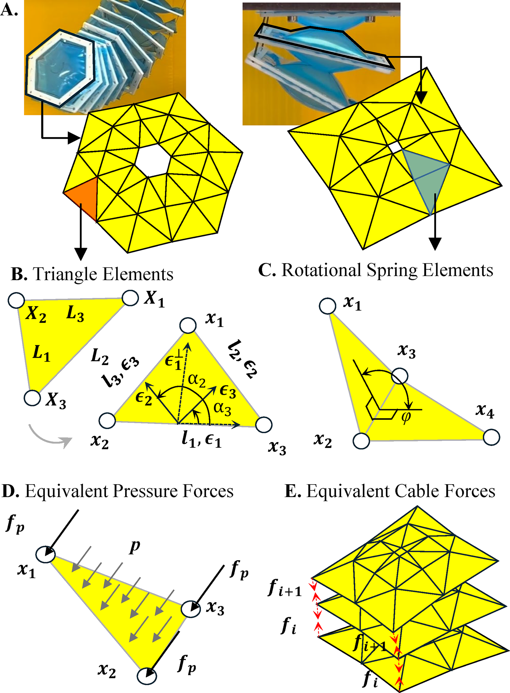
Figure 3A illustrates the proposed model for the cable pneumatic robot. This lumped parameter model can be seen as a coarsely meshed FEM with specially derived lump elements.33,34 This modeling strategy is similar to the bar and hinge model for origami system,35,36 the lattice model for thin membranes,
37
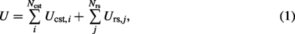
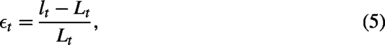
or the pseudo-rigid-body model for compliant mechanisms.38,39 In the proposed model, the pneumatic cores are represented using a combination of special triangle elements and rotational spring elements. The triangular elements capture the in-plane stiffness of membranes, and the rotational springs capture the out-of-plane bending stiffness. The total potential energy of the cable pneumatic system is the summation of all triangle and rotational spring elements as follows:


The equilibrium of the system is obtained by tracking how the deformation

By solving Eq. (4), the proposed model can efficiently capture the motions of cable pneumatic robots under internal pressure, cable tension, and external loading. The simulation is significantly faster than FEM because the model has a smaller number of degrees-of-freedom. Moreover, the model accurately captures the global mechanical behavior of the system.
3D constant strain triangle
This work adopts a constant strain triangle element derived in the study by Zhu.
33
In the following subsection, we illustrate how this element differs from traditional FEM derivation. In FEM, solving the stiffness matrix
On the other hand, the proposed model approaches the derivation differently (see Fig. 3B). Assume that the deformed nodal coordinates of a triangular element are


By solving the above two equations, we can obtain
4-Node rotational spring
We use rotational springs to capture the bending stiffness of thin membranes. These rotational springs are like door hinges with rotational stiffness. Figure 3C shows the derivation of this element, where

Where
Technically, the film’s in-plane extension is the primary mechanism that balances internal pressure, while the bending stiffness of the thin film is mostly negligible. Thus, the membrane requires a large deformation to achieve equilibrium. However, introducing rotational springs provides additional numerical stabilization, leading to improved convergence performance. This enables us to use a Newton–Raphson nonlinear solver rather than the more computationally expensive dynamic relaxation for tracking the equilibrium shapes.
Pressure, cable actuation, and nonlinear solvers
Figure 3D demonstrates how we model the internal air pressure. We assume that the air pressure is uniform and the force direction is normal to the element surface. The equivalent nodal force from air pressure is as follows:

Here, we use the Newton–Raphson method to track the nonlinear equilibrium of the cable pneumatic robots. This method is incremental-iterative. First, the full load is broken into several small increments. Then, the iterative Newton’s method is used to find the equilibrium of each increment. In each iteration, we need to solve the following linearized system equation:

A MATLAB implementation package is developed to run the proposed lumped parameter model. This simulation can be found in the Supplementary Data. We next validate the performance of this simulation platform through experiments.
Model Verification with Experiments
Three-point bending test
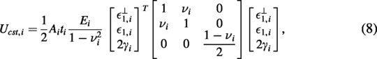
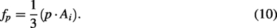
We first conducted a three-point bending experiment to evaluate whether the proposed model can capture the bending stiffness of the pneumatic chamber. First, Figure 4A illustrates the relationship between the extension length and the applied internal pressure. This pneumatic core can extend to more than 3.5 times its storage length, highlighting its superior extension and compact storage capability. Next, Figure 4B, C presents the experimental and simulation load-displacement curves at different internal pressures. The experimental setup is shown in Figure 4F–H, and the simulated deformation is shown in Figure 4I-K. These results show that the proposed simulation can accurately predict the bending stiffness of the pneumatic core. Running the simulation in Figure 4I–K requires 48 s on a laptop computer with an Intel i7 CPU, demonstrating the high computational efficiency of the proposed simulation.
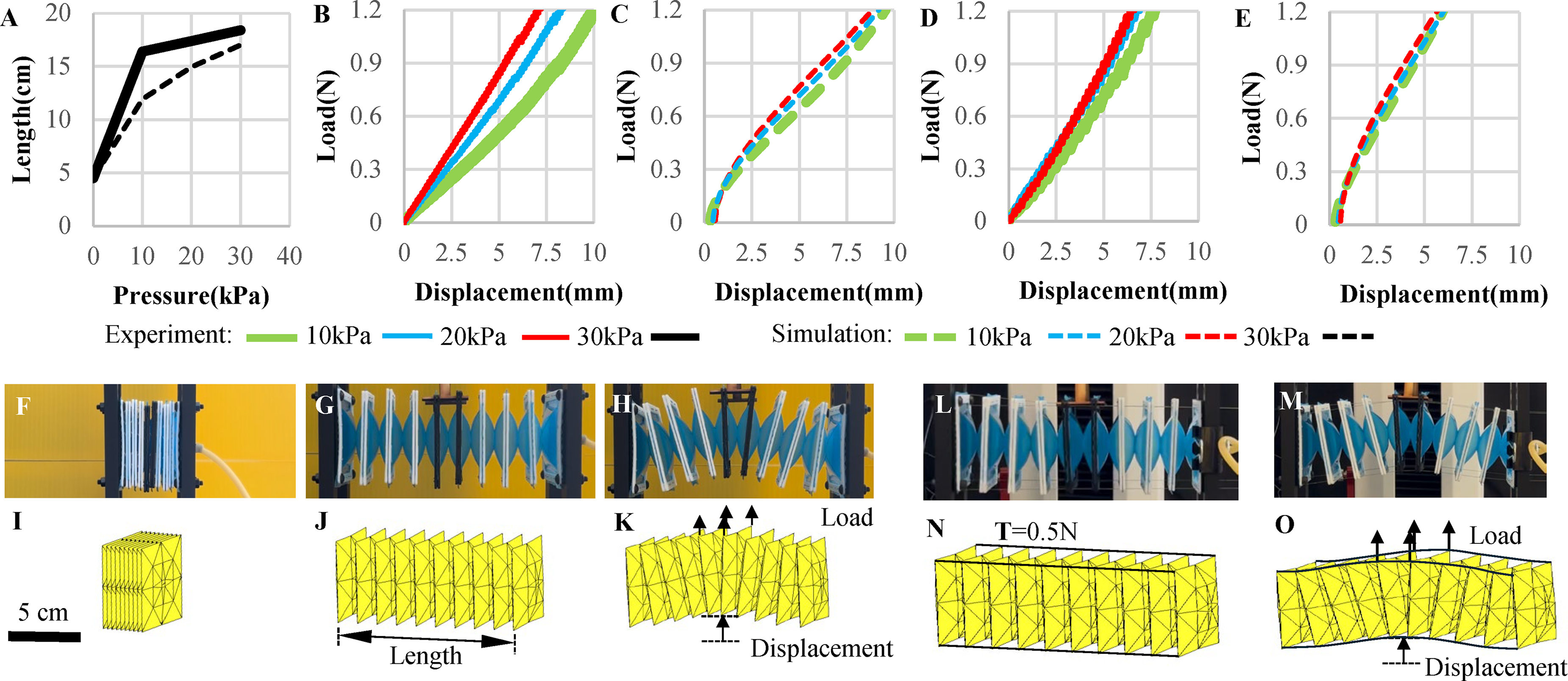
Comparison of bending stiffness between experiments and simulations.
In addition, we repeated the experiments when additional cable tension is applied (Fig. 4D, E). Four cables are attached to the four sides of the structure, and each cable is loaded using a 50 g weight. The same setup is replicated in the simulation, where the cable tension is modeled as pairs of 0.5 N forces. Figure 4D, E presents the experimental and simulated load-displacement curves at different internal pressures. In addition, Figure 4L, M shows the experimental setup and Figure 4N, O shows the simulation results. These results show that the simulation can accurately predict the additional stiffness due to the applied cable tension.
Bending angle test
Next, we investigate the relationship between the bending angle and the applied cable tension. Figure 5A, B illustrates the experimental setup, and Figure 5C presents the corresponding simulation. Figure 5D, E shows the experimental and simulated results for the relationship between bending angle and cable tension with no tip load applied. We can see that the proposed model can capture the rotational deformation accurately. In addition, we applied a 0.5 N tip force to the end of the actuator and repeated the experiment. In this situation, the actuator will first bend in the negative angle direction due to the applied tip forces. After applying the cable tension, the actuator will bend back to the positive angle direction. Figure 5F presents the experimental results, and Figure 5G shows the simulation results. As shown, the simulation can closely reproduce the experimental results even when there is a tip load applied. Running the simulation for both stretching and bending in Figure 5G requires only 16 s on a laptop computer with an Intel i7 CPU, highlighting its high computational efficiency.
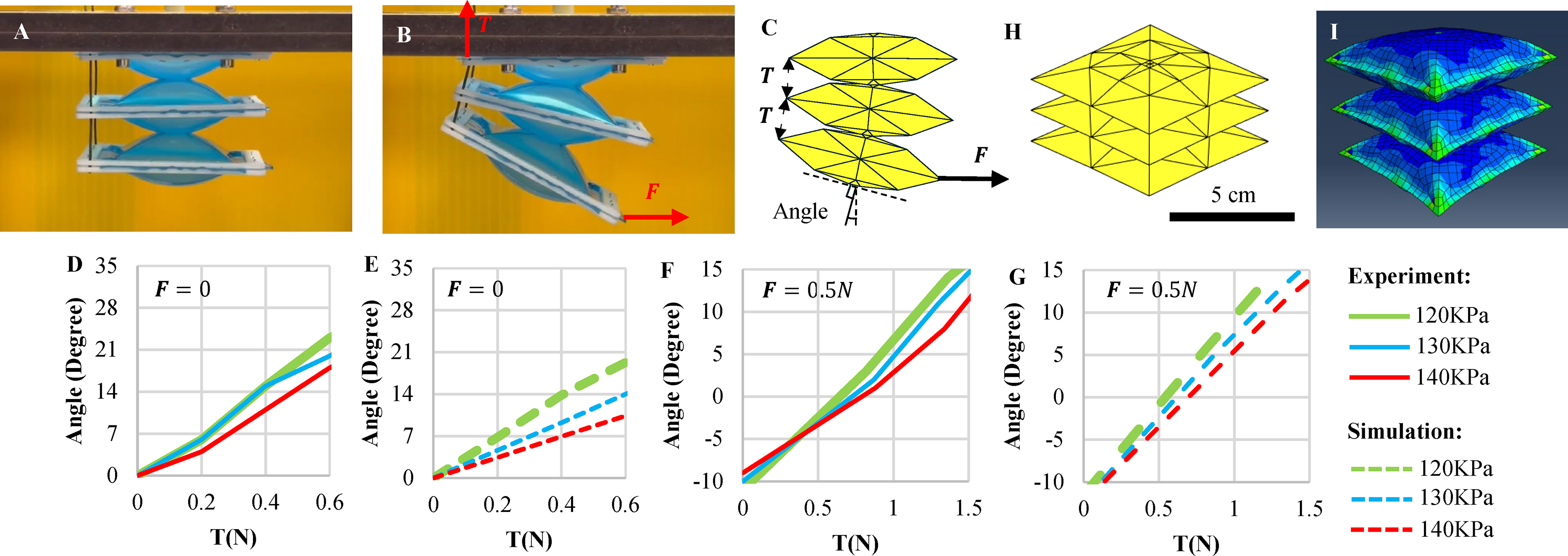
Relationship between bending angle, cable tension, and tip load.
Next, Figure 5H–I shows a comparison between our simulation and the FEM simulation in Abaqus. Shell elements are used to model the pneumatic core with identical material properties and film thickness. In this comparison, we simulate a three-unit pneumatic core inflated to a pressure of 10 kPa with no cable tensions or tip forces. As shown, both simulations can reproduce the correct deformation. However, running the lumped parameter model takes a wall-clock time of 6 s, whereas running the FEM in Abaqus takes a wall-clock time of 46 s. This result demonstrates that the proposed simulation is more efficient than traditional FEM simulations. Moreover, as we will show later, the proposed simulation platform can be integrated into common robotic simulation environments, which is not possible with traditional FEM software programs like Abaqus or ANSYS.
Overall, these verification results show that the proposed simulation model effectively captures the underlying physical behaviors of the cable pneumatic robots. Although its accuracy may be lower than the top-rank FEM simulation, the rapid computational speed is highly advantageous for inverse design and controller developments.
Demonstration Examples
Three-finger gripper
The first demonstration example is a three-finger cable pneumatic gripper (see Fig. 6). The gripper has three cable pneumatic fingers driven by a NEMA-17 motor and a gearbox. Figure 6A–C shows the gripper grasping a plant, highlighting its capability to handle irregularly shaped objects. In addition, Figure 6D–F presents the simulation results that replicate the grasping motions. Running this simulation requires 91 s using a laptop computer with an Intel i7 CPU, while the physical demonstration takes about 80 s, including inflating the fingers and grasping the plants. This demonstrates the close-to-real-time computational performance of the proposed simulation. In addition to lifting a plant, the gripper can also grasp other objects, such as article towel rolls and electric wire spools, as shown in Figure 6G, H. These results demonstrate that the proposed gripper design is highly versatile and capable of handling a wide variety of objects.
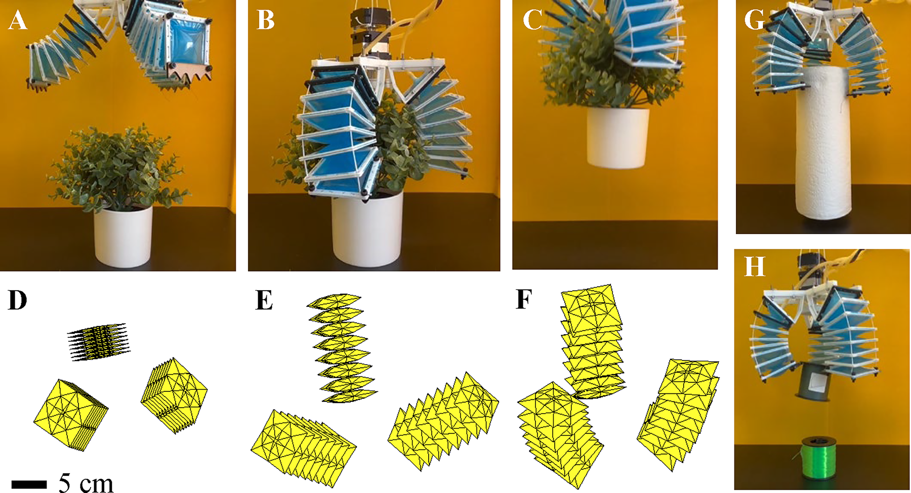
Three-finger gripper.
Omnidirectional robotic arm
The second prototype is a hexagonal pneumatic robotic arm capable of omnidirectional bending. When inflated, the arm can extend to over five times its unpressurized length, highlighting its large axial extension capability. In addition, the design incorporates three individually controlled cables, enabling the arm to bend toward arbitrary directions. By coordinating pneumatic pressure with cable actuation, the arm can achieve a wide range of motions. Figure 7A–C shows the full actuation process where the robot extends to its maximum length and bends toward different directions. Furthermore, Figure 7D–F presents the simulation result that replicates the full actuation process. Running this simulation takes 73 s on a laptop computer with an Intel i7 CPU. Implementing inflation and bending motion in reality takes about 50 s so the simulation is not significantly slower than the real prototype. Furthermore, please note that the simulation is not implemented in a fast programming language (like C++) and is not parallelized. Both methods could further speed up the simulation by orders of magnitude.
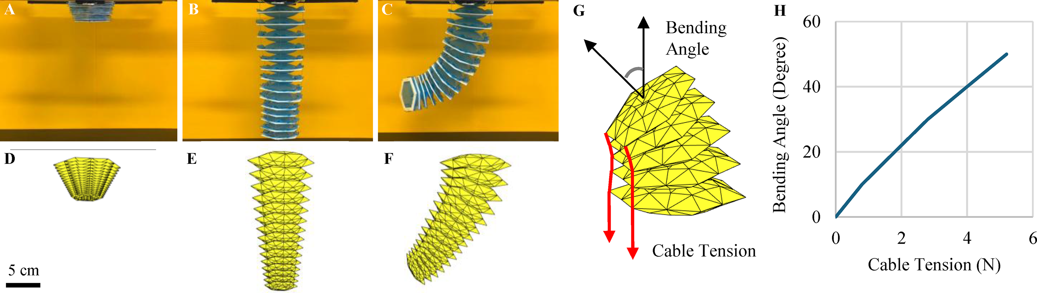
Cable pneumatic robotic arm.
In addition, we implemented a simple controller to modulate the bending angle of this robotic arm (see Fig. 7G and Supplementary Data “Hexagon_Arm_Control.m”). If the bending angle is smaller than the target, the controller will add cable tension. Otherwise, the controller will reduce the cable tension. Figure 7H shows the relationship between the target angle and the cable tension found using the code. This example shows that the proposed simulation could be used for developing a new controller. However, we want to acknowledge that we had not considered sim-to-real challenges, such as measuring real bending angles or creating control paradigms for 3D trajectory tracking. These tasks are beyond the scope of this work and are promising future research directions.
Robotic arm with end gripper
The third prototype is a cable pneumatic robotic arm equipped with an end gripper. Figure 8 presents the design of this robot. The body of the arm robot is similar to the design presented in Figure 7, and a pneumatic gripper is added at the tip to enable manipulations. Figure 8A–E demonstrates how the robot can unroll electric wire from a spool. The robot arm can reach toward the wire, grip the wire firmly, and pull it outward. This sequence can be repeated to extract more wires. A Supplementary Video is provided to demonstrate the full procedure in action. In addition, Figure 8F illustrates how the robotic arm can grasp a deployable bridge toy and lift it off the ground, demonstrating the gripping strength and lifting capacity.
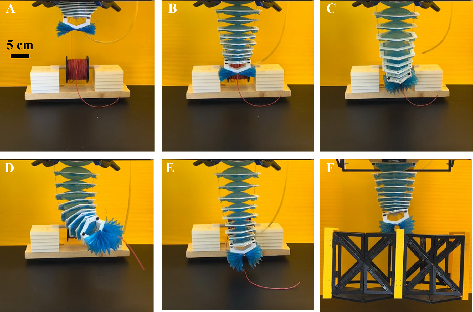
Pneumatic cable-driven robotic arm with an end gripper.
Cosimulation with cobots
Finally, we demonstrate a simulation example where we simultaneously capture the inverse kinematics of a UR5e cobot and the motion of a cable pneumatic robot. In this scenario, a cable pneumatic robotic arm is mounted at the end of the UR5e and is therefore treated as the robot’s end effector. We model the UR5e using the robotic toolkit in MATLAB and command it to reach a specified target position using inverse kinematics algorithms. We also use the proposed simulation to capture the deformation of the cable pneumatic robot. Figure 9A shows the deflated soft robot mounted on the UR5e cobot, with its tip initially pointing toward the ground. After inflation, as shown in Figure 9B, the soft robot elongates. In Figure 9C, the UR5e rotates the attached cable pneumatic end effector so it sags downward under its own weight. Finally, Figure 9D shows how we apply cable actuation to overcome gravity and bend the end effector upward. Running this cosimulation takes 146 s using a laptop computer with an Intel i7 CPU. This case study demonstrates that the proposed simulation platform can be integrated with conventional robotic simulation environments to simultaneously capture the motion of a cobot and a soft robotic end effector. This cosimulation capability supports inverse design of new robots and the development of controllers for hybrid systems that combine soft and rigid components.
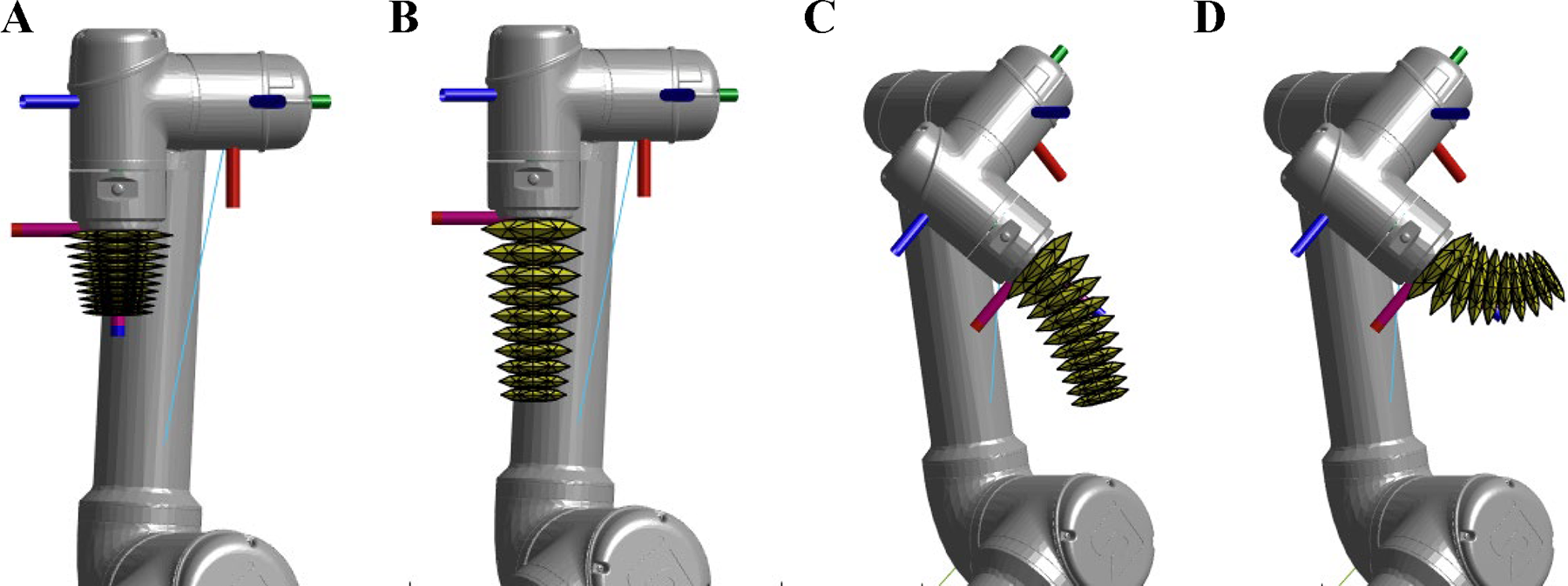
Simulate Universal Robots (UR5e) robot arm working with the cable pneumatic robot.
Conclusion
In summary, this work presents a new class of cable pneumatic soft robots that are highly compliant, lightweight, and capable of large deformation. These robots can generate complex, controllable motions and advanced manipulation functions. In addition, we developed a lumped parameter model for the robots and validated it through experiments. Our results demonstrate that the model can accurately and efficiently capture the mechanical behavior of these soft robots.
Despite these advances, future research can further improve the proposed fabrication and simulation framework. First, this work had not explored the autonomous control of cable pneumatic robots in detail. Future works can create trajectory tracking and closed-loop control paradigms based on the developed simulation capability and soft robot control methods summarized in the review article. 1 In addition, it is beneficial to explore different structural materials for films and cables to improve durability, achieve softer grips, or enhance output forces. Furthermore, the proposed design provides limited torsional degrees-of-freedom. This characteristic simplifies the construction of the robot but limits the achievable range of motions. With special cable alignment, the design could achieve a small torsion. Future works could explore alternative configurations to enrich the motion of this design by exploring different chamber designs, asymmetrical placement of chamber connection holes, and spiral cable placements. Finally, although the proposed simulation captures the global mechanical behaviors, its accuracy could be further improved using data-driven or machine learning–based approaches.
Overall, this work demonstrates the high adaptability of the proposed cable pneumatic soft robots. The robots can achieve multiple configurations, grasp irregular objects, and perform complex functions. Furthermore, the proposed lumped parameter model provides a promising simulation approach for soft robotic structures, because it captures the underlying physics and is computationally efficient. More significantly, the proposed simulation can be integrated into existing robotic simulation environments. This compatibility enables cosimulation of rigid cobots and soft robotic end effectors, enabling the lumped parameter model to have a broad range of applications.
Access to Simulation Code
The simulation code can be found in the Supplementary Data. Alternatively, the simulation is also found at GitHub: https://github.com/zzhuyii/Sim-FAST.
Footnotes
Author Disclosure Statement
The authors declare no competing interests.
Funding Information
The funding support is received from the faculty start-up from Michigan Technological University.
Supplemental Material
Supplemental Material
References
Supplementary Material
Please find the following supplemental material available below.
For Open Access articles published under a Creative Commons License, all supplemental material carries the same license as the article it is associated with.
For non-Open Access articles published, all supplemental material carries a non-exclusive license, and permission requests for re-use of supplemental material or any part of supplemental material shall be sent directly to the copyright owner as specified in the copyright notice associated with the article.