
Abstract
Endovascular interventions demand catheters that can actively steer through tortuous vessels and dynamically increase stiffness at the target to ensure precise therapy. Most existing steerable catheters achieve steering and variable stiffness (VS) by multiple sources, leading to reduced efficiency advantage, increased bulkiness, and safety risks. This work introduces a magnetic jamming method that allows steering and VS using one magnetic source. First, a carrier-free, matrix-free magnetic jamming scheme is introduced that directly encapsulates soft-magnetic powder in coaxial thin-walled tubes, enabling single-source field-driven steering and reversible VS via interparticle jamming. Next, an analytical micro-to-macro stiffness model is established that explicitly links field parameters and particle properties to catheter-level outputs (i.e., stiffness and steering angle) by incorporating particle interaction, thus providing closed-form, physics-based estimations. Finally, we validate the method at both tip and catheter levels, confirming the stiffness model and substantial field-tunable stiffness modulation (up to 300-fold), with benchmarking against vacuum jamming as a reference to validate its effectiveness and demonstrating a multifunctional prototype that enables both steering and VS using a single magnetic source. Our magnetic jamming approach enables on-demand steering and rapid, large-range stiffness modulation in millimeter-scale catheters, promising faster navigation with lower contact forces, more stable device deployment, and a clearer path to autonomous, workflow-friendly endovascular interventions.
Introduction
Visceral arterial disorders, such as hepatic artery pseudoaneurysms and splenic artery aneurysms, are predominantly managed via endovascular catheter-based interventions. These procedures are complicated by the intricate and tortuous branching patterns and relatively fragile vessel walls that are prone to perforation, pseudoaneurysm formation, and hemorrhage. Consequently, catheters must provide reliable navigability to access distal targets safely, applying minimal contact forces along complex pathways. Once positioned, the catheter needs to deploy and precisely manipulate therapeutic devices, such as coils, microstents, or embolic agents. However, under back-reaction from these instruments and hemodynamic disturbances, the distal catheter tip is susceptible to deformation, which can impair deployment accuracy and stability. Thus, visceral arterial interventions demand two critical catheter capabilities: active steering for dexterous navigation and tunable stiffness for stable therapy delivery.
Catheter steering strategies can be divided into tethered steering and untethered steering, based on whether steering actuation requires proximal-to-distal transmission along the catheter. Tethered steering relies on direct mechanical or fluidic transmission along the catheter body to achieve tip deflection. Common tethered approaches mainly include cable-driven structures, 1 concentric-tube structures,2,3 and hydraulic/pneumatic pressurization with wall chambers.4,5 Overall, tethered steering approaches offer high device-side integration, compatibility with existing interventional workflows, and well-established modeling and control. However, their reliance on proximal-to-distal transmission introduces backlash and friction losses, reduces distal responsiveness and accuracy in tortuous anatomy, and increases the risk of tissue trauma due to higher insertion forces.
In contrast, untethered steering achieves distal tip deflection and orientation control through direct generation of actuating forces or torques at the distal segment (typically via responsive elements that react to externally applied stimuli), without requiring proximal-to-distal transmission along the catheter length. This approach enables high-bandwidth, precise steering even in highly curved, high-friction, or branching vessel networks. Common untethered steering includes light-based actuation,6–9 electrical actuation,10,11 chemical actuation,
12
ultrasound actuation,
13
and magnetic actuation. However, constrained by optical attenuation in tissue, insulation and encapsulation challenges at high voltage, the need for safe, sustained chemical gradients, and the relatively small propulsive forces achievable with ultrasound, many untethered steering methods have seen limited adoption in robotic catheters. In contrast, due to safe penetrability and considerable steering torque, magnetic steering has been applied in catheter/guidewire and can be categorized based on the characteristics of magnetized elements. (1) Permanent magnet14–16: When a permanent magnet is typically placed near the distal end (e.g., a tip micromagnet or a magnetized terminal segment), its dipole rapidly aligns under a uniform field torque, enabling miniaturized, high-bandwidth distal orientation and closed-loop control. (2) Soft-magnetic material17,18: High saturation magnetization of soft-magnetic material (such as iron-cobalt alloy or bearing steel) allows magnetic gradient-generated body forces to pull or steer the catheter. (3) Hard-magnetic elastomer with programmed magnetization19,20: Embedding hard-magnetic particles in an elastomer and programming their magnetization produces distributed torques across the magnetized regions under a uniform field, enabling programmable curvature patterns and large attainable bending. (4) Distributed electromagnetic coil sets under MRI21–23: One or more discrete electromagnetic coil sets are arranged axially near the distal end of the catheter/guidewire. By modulating the currents in these coils within the homogeneous main magnetic field
The above catheters mainly focus on steering. To provide more stable distal support during interventions, steerable catheters often integrate variable-stiffness (VS) mechanisms. These approaches span phase-changing materials (electrorheological fluid, 24 shape memory alloy [SMA], 25 shape memory polymers [SMP],26–34 low-melting-point alloy [LMPA]35–42), jamming methods (i.e., particle jamming, 43 fiber jamming,44,45 layer jamming46,47), and structure-based methods (i.e., antagonistic cable tensioning,48–51 mechanical locking,52,53 sliding concentric rigid tube/wire,54–56 magnetically actuated mechanical locking 57 ). Collectively, these advances have substantially expanded the functional envelope of steerable catheters and improved controllability.
While magnetic steerable catheters have shown highly promising capabilities, especially in terms of their miniaturization potential and untethered tip manipulation, they typically achieve magnetic steering and VS via two different sources. This brings about the following three issues. (1) Compromised efficiency advantage. The seconds-to-minutes response time of existing VS methods offsets the rapid, millisecond-scale benefits of magnetic steering. (2) Cross-sectional occupation. Additional heating elements, pneumatic channels, or concentric tubes/tendons are required inside the catheter, consuming cross-sectional area, squeezing space for perfusion/drug delivery/sensors, and limiting compliance and potential for miniaturization. (3) Safety risks. Heat, pressure, or antagonistic force could damage fragile vasculature. In summary, the bottleneck lies in the “dual-source” nature. If both steering and VS can be achieved by magnetic source, then the above issues could be addressed in a unified manner. Even in approaches that utilize a single magnetic source for both steering and stiffening through magnetically actuated mechanical locking, 57 the VS relies on mechanical displacement of macroscopic components, resulting in seconds-scale response times (6–14 s) and additional structural complexity that limits full realization of these benefits.
Recent studies have shown that external magnetic fields can induce attraction between soft-ferromagnetic constituents and trigger “dipolar chaining,” 58 “magnetorheological (MR) phenomenon,”59–61 or “jamming with magnetic composites,” 62 which can potentially be adopted for stiffness tuning. These works observed the process of chaining experimentally, 58 established the basic mechanical behavior of magnetorheological fluids theoretically,59,60 or demonstrated a untethered multi-axis selectable magnetic jamming using soft-ferromagnetic composites. 62 Given the small cross-sectional area of catheters (millimeter scale), where a central lumen already occupies part of the cross-section, the remaining space must be used with maximum efficiency (i.e., maximizing the magnetic energy density of the remaining space). However, carrier fluid in MR fluid displaces particle volume, reduces the attainable stiffness ceiling, and its high flowability introduces leakage risk. Jamming with magnetic composites presents several characteristics relevant to catheter integration. (1) The nonmagnetic matrix occupies part of the subunit volume without contributing magnetic attraction forces; and (2) the demonstrated prototypes are centimeter-scale assemblies, and scaling the composite subunits down to the millimeter regime for catheter use would require significant reductions in feature size while maintaining precise multimaterial fabrication.
Overall, current magnetically steered VS catheters rely on dual sources for steering and stiffening, which compromises efficiency, increases cross-sectional footprint, and introduces safety risks (e.g., heat, pressure, antagonistic forces). In light of these limitations, we introduce a single-source magnetic particle jamming approach that, under one magnetic input, steers the catheter tip or modulates its stiffness as required. It achieves up to 300-fold stiffness modulation in a 4 mm outer diameter (OD) tip, millisecond-scale response (<20 ms), and quasi-continuous set-point control. Compared with dual-source designs, it requires no additional pressure/thermal lines, reducing integration complexity for small-diameter catheter tips. The two novel contributions of this article include:
Proposing a carrier-free, matrix-free magnetic jamming scheme: Utilizing soft-magnetic powder as the sole jamming medium, directly encapsulated within coaxial thin-walled tubes. Under a single external magnetic input, interparticle attraction and force-chain formation enable integrated reversible magnetic jamming and steering. Compared to alternative schemes such as MR fluids and jamming with magnetic composites, this approach offers a high particle packing fraction ( Developing a micro-to-macro stiffness model for magnetically jammed steerable robotic catheters. Our formulation advances predictive stiffness modeling by delivering closed-form expressions that directly map magnetic field parameters (e.g.,
In the rest of the article, Design of magnetic catheter details the structural design and fabrication of the device. The Stiffness Model of Magnetic Tip and Static Steering Model of Magnetic Tip sections establish the analytical models for tip stiffness and deflection angle, respectively. These models, along with the magnetic tip's characterization and the catheter's overall performance, are then evaluated in the Experimental Validation section. Finally, the Discussion section delves into the choice of particle materials, jamming mechanism, biocompatibility, variable bending radius capability, interparticle interactions, Halbach array configurations, and a benchmarking comparison with alternative variable-stiffness methods.
Design of Magnetic Catheter
Our goal is to develop a magnetically jammed steerable catheter that can be navigated via a transfemoral approach to the proximal side of a target branch ostium in the common hepatic or splenic artery. Once in position, the catheter can dynamically increase its stiffness to enhance resistance to bending, thereby improving the alignment and deployment accuracy of micro-occlusion/embolization devices (e.g., detachable coils, particles/pastes, and umbrella-like micro-occluders) at branch ostia. Based on this objective, we define the following design specifications.
Dimensions: Considering adult anatomy, the common hepatic artery has a diameter of approximately 4–7 mm and the proximal splenic artery about 4–6 mm.
65
We set the catheter OD to 4 mm ( Bending capability: The celiac trunk-hepatic/splenic artery bifurcation angle is approximately 40°−130° (and may be larger in tortuous splenic arteries).
66
The catheter should provide at least Stiffness: To counter deployment recoil,
67
the hard-state equivalent bending stiffness should be at least 10–20 mN/mm, thereby providing a stable platform for precise positioning and deployment of micro-occlusion/embolization devices within the release window.
According to the above design criteria, a magnetically jammed steerable robotic catheter is designed (Fig. 1). It mainly consists of a magnetic tip and a catheter body (Fig. 1a), both of which have a hollow working channel. In the working channel, a polyether ether ketone (PEEK) tube runs through the entire catheter (Fig. 1b). The PEEK tube not only provides a low-friction inner surface for smooth delivery of surgical tools but also can freely slide axially within the catheter. During navigation, the PEEK tube is retracted proximal to the magnetic tip, allowing the tip to remain maximally soft and compliant. Upon reaching the target position, internal tools can be advanced through the PEEK tube and operate on the target. The sharpened distal tip of the PEEK tube can also be extended beyond the magnetic tip and perform puncture. The magnetic tip consists of two concentric soft silicone tubes and plenty of micron-sized iron particles wrapped by the two tubes. The catheter body has a balloon on its distal end, which can anchor the root of the magnetic tip to the inner wall of the blood vessel.
Design of magnetically jammed steerable catheter. 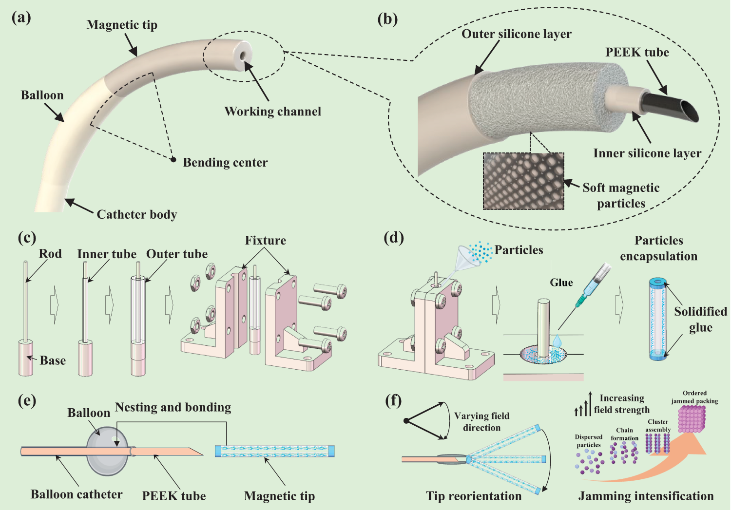
The fabrication of a magnetic catheter includes three steps.
Clamping of the magnetic tip (Fig. 1c). Insert an alignment rod coaxially into the blind hole of the base. Slide the inner tube over the rod until it sits on the base. Then place the outer tube onto the base so that its top end face is flush with that of the inner tube. Close the two-sided clamps to wrap the outer tube and secure them with threaded fasteners. This step ensures that the inner and outer tubes are strictly concentric and not inflated by the filling pressure of particles. Particle encapsulation (Fig. 1d). Using a microfunnel, fill the annular cavity between the inner and outer tubes with soft-magnetic particles. Densify the particles with a small vibration motor to eliminate voids caused by interparticle frictional self-locking. Once the cavity is fully filled, dispense adhesive to seal the top end faces of the inner and outer tubes. Invert the fixture, remove the catheter, trim the portion of the outer tube protruding beyond the inner tube, and repeat the vibration-densification and glue dispensing to seal the bottom end faces, yielding the magnetic tip. This step ensures the particles are densely packed and reliably encapsulated. Catheter integration (Fig. 1e). Thread a PEEK tube sequentially through the balloon catheter and the magnetic tip, then bond the mating interfaces between the catheter body and the tip with adhesive. The resulting assembly is a magnetic catheter. This step ensures smooth delivery of internal tools due to the much lower friction against the PEEK tube compared to silicone. Additionally, the PEEK tube remains axially slidable, allowing it to be retracted proximal to the magnetic tip during navigation to maintain maximal tip softness and extended with a sharp needle for puncture upon reaching the target.
As shown in Figure 1f, the jammed particles endow the tip with two functions. (1) Magnetic steering: Changing the external field direction realigns the anisotropic particle network inside the slender tip (chains/clusters align with the field), generating a magnetic moment and torque that rotate the tip toward the field, enabling steering. (2) VS: Increasing magnetic induction drives a microstructural evolution from dispersed particles to chain formation, cluster assembly, and finally ordered jammed packing; rising dipole attraction elevates contact pressure and friction within the network.
Stiffness Model of Magnetic Tip
This section develops an analytical model for the lateral stiffness of the magnetic catheter tip under an external magnetic field. The stiffness arises primarily from magnetically induced particle chains that resist lateral deflection, combined with the elastic resistance of the soft tubes. We first analyze chain formation and interparticle forces based on dipole interactions, then derive the magnetic resistance to lateral load, and finally obtain the total stiffness expression.
Considering the significantly larger lateral deflection than axial deformation experienced by the catheter tip during a surgical operation, here we focus on modeling the lateral stiffness of the magnetic tip. In Figure 2a, outer/inner diameters of outer tube and inner tube are respectively
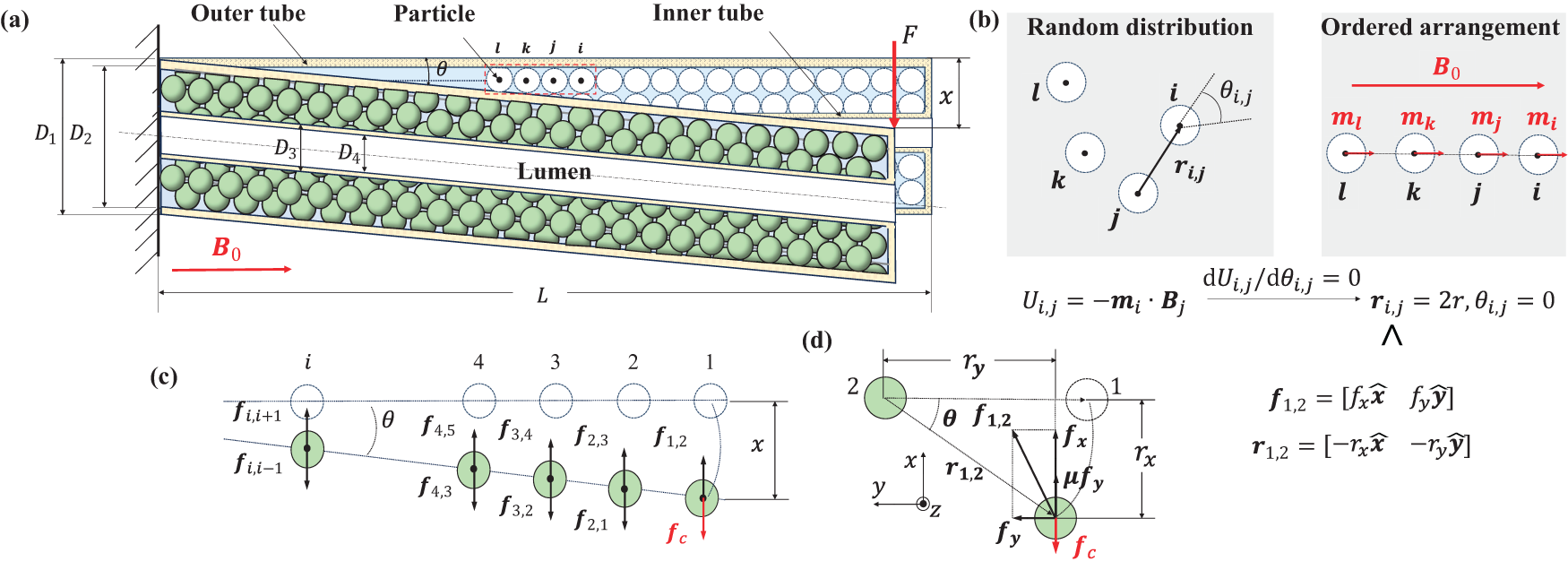
Deflected magnetic tip under lateral load.
Magnetically induced particle aggregation and chain formation in the wall chamber of catheter tip
This subsection explains how soft-magnetic particles aggregate into chain structures when an external field
In the absence of a magnetic field, the soft-magnetic particles exhibit negligible remanence (typical remanence Mr < 1 emu/g, remanence ratio Mr/Ms < 0.5%; see Supplementary Table S1), allowing free flow and high compliance of the tip. Upon application of an external field

Once particle j is magnetized, it will generate a nonuniform magnetic field

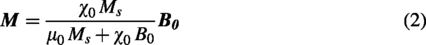
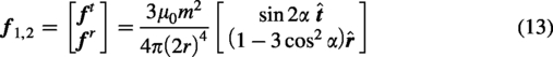
Under magnetic field

According to Eqs. (1) and (2),
Deflection of magnetic tip under lateral load
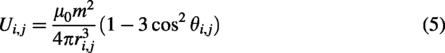
This subsection derives the magnetic forces resisting lateral deflection of the particle chains. Focusing on nearest-neighbor interactions within a chain, we use the dipole interaction energy and virtual work principle to calculate the force components when the tip is tilted by angle
When a lateral load F is applied, the magnetic tip is deflected by a lateral displacement x. Particles at the distal end of magnetic tip first undergo lateral displacement x and then drag nearby particles slightly away from the distal end to move together. If each chain in magnetic tip is the set of particles i (i is the serial number of each particle of each chain,


By substituting
According to Figure 2d,
Effective stiffness of the multiparticle magnetic tip
Considering the lateral load F is balanced with the magnetic force
Stiffness of magnetic tip includes instantaneous tangent stiffness
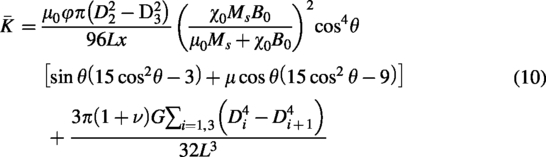
This model gives the analytic relationship between the tip stiffness
Static Steering Model of Magnetic Tip
Under an axial magnetic field, particle aggregation and chain formation within the magnetic tip (as detailed previously) establish the initial configuration shared by both the stiffness model and the steering model. The differences arise from the actuation source. When an external lateral force is applied at the distal end, the particle chains undergo passive bending; this process has been analyzed to derive the stiffness model. In contrast, when the axial magnetic field rotates or tilts, the particle chains actively follow the field direction; this process is analyzed to derive the steering model.
In the stiffness model, an external lateral force is applied at the distal end of the tip during cantilever bending tests. Deformation initiates at the distal (outermost) particle and propagates inward, creating a tendency for relative tangential (slip) motion between adjacent particles. Although the particles ultimately move largely together, the combination of strong axial magnetic attraction and this lateral slip tendency activates frictional forces at the particle-particle contacts. This frictional contribution, together with the magnetic forces, plays a key role in the overall stiffness. In contrast, in the static steering model, the tip is actuated purely by a rotating or tilted magnetic field. All particles experience nearly simultaneous and uniform changes in magnetic torque, resulting in coherent collective rotation of the chain with negligible relative tangential motion between adjacent particles. Consequently, interparticle friction can be reasonably neglected in this regime, allowing a simplified analytical treatment focused on magnetic torque balance.
This section establishes a model for the static steering angle
During the steering process, a magnetic field with a tilted angle of
The magnetic tip has no fixed N-S pole. If the angle
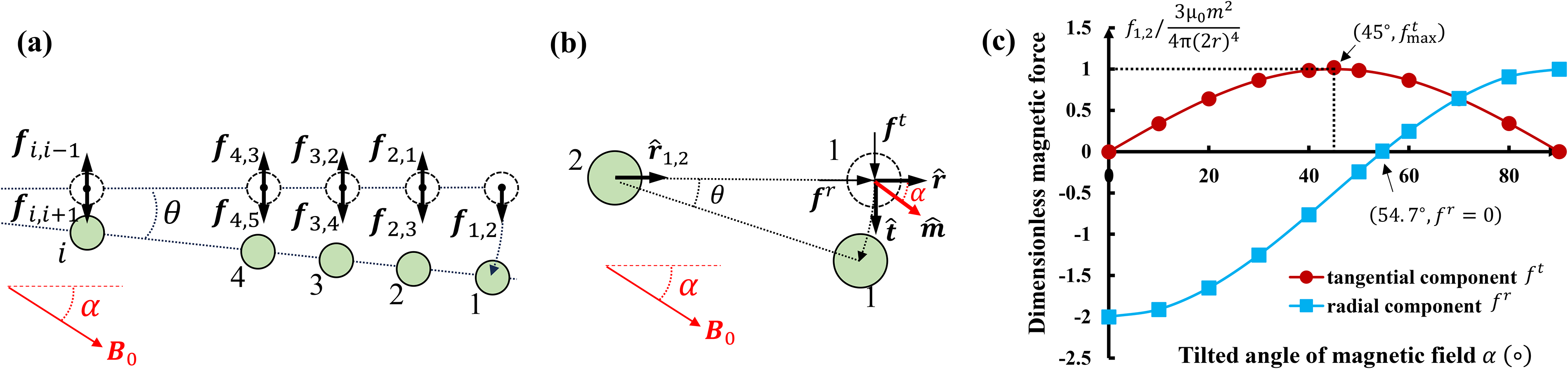
When the tilted magnetic field is applied (Fig. 3a), each particle in the single chain will be subject to
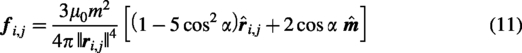
Steering effect of tilted magnetic field.
where
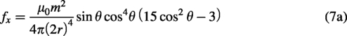
Taking particle 1 as an example and substituting
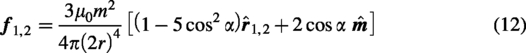
To present the effect of
The variation of dimensionless magnetic force
Other magnetic forces

The steering torque T starts to steer the tip to follow the direction of magnetic field while the resistance from the elastic force of tubes
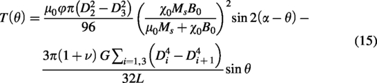
As

For the magnetic tip, its magnetic coefficient P is usually far higher than its elastic coefficient Q.

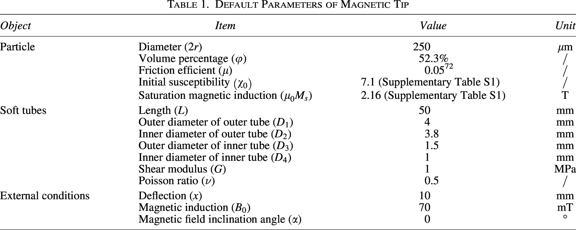
For the magnetic tip given by Table 1, when
Default Parameters of Magnetic Tip
Experimental Validation
In this section, we present two sets of experiments: one on a 50 mm length magnetic tip and another on a magnetically jammed steerable catheter. For the tip, we first measured stiffness to validate the analytical model, then quantified how stiffness varies under different magnetic fields and benchmarked it against the established vacuum-driven jamming approach to validate the effectiveness of magnetic jamming in achieving substantial stiffness modulation. We further characterized static steering by measuring deflection angle and output torque, thereby validating the steering model. For the catheter, we fabricated a multifunctional prototype and conducted three proof-of-concept studies, demonstrating that both active steering and stiffness variation can be achieved using a single magnetic source.
Characterization tests for magnetic tip
Force-displacement test and stiffness model validation
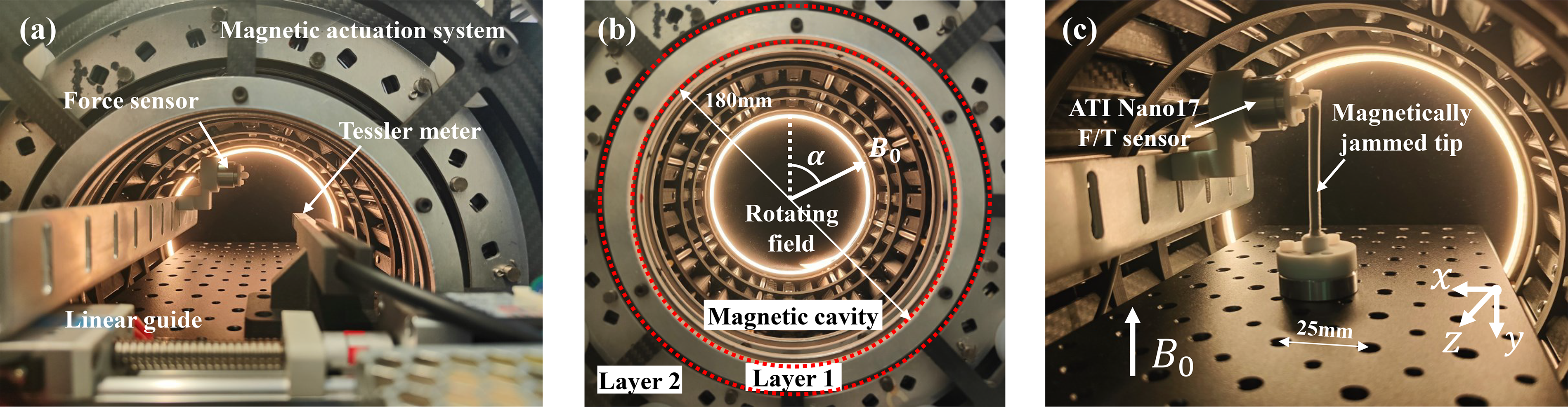
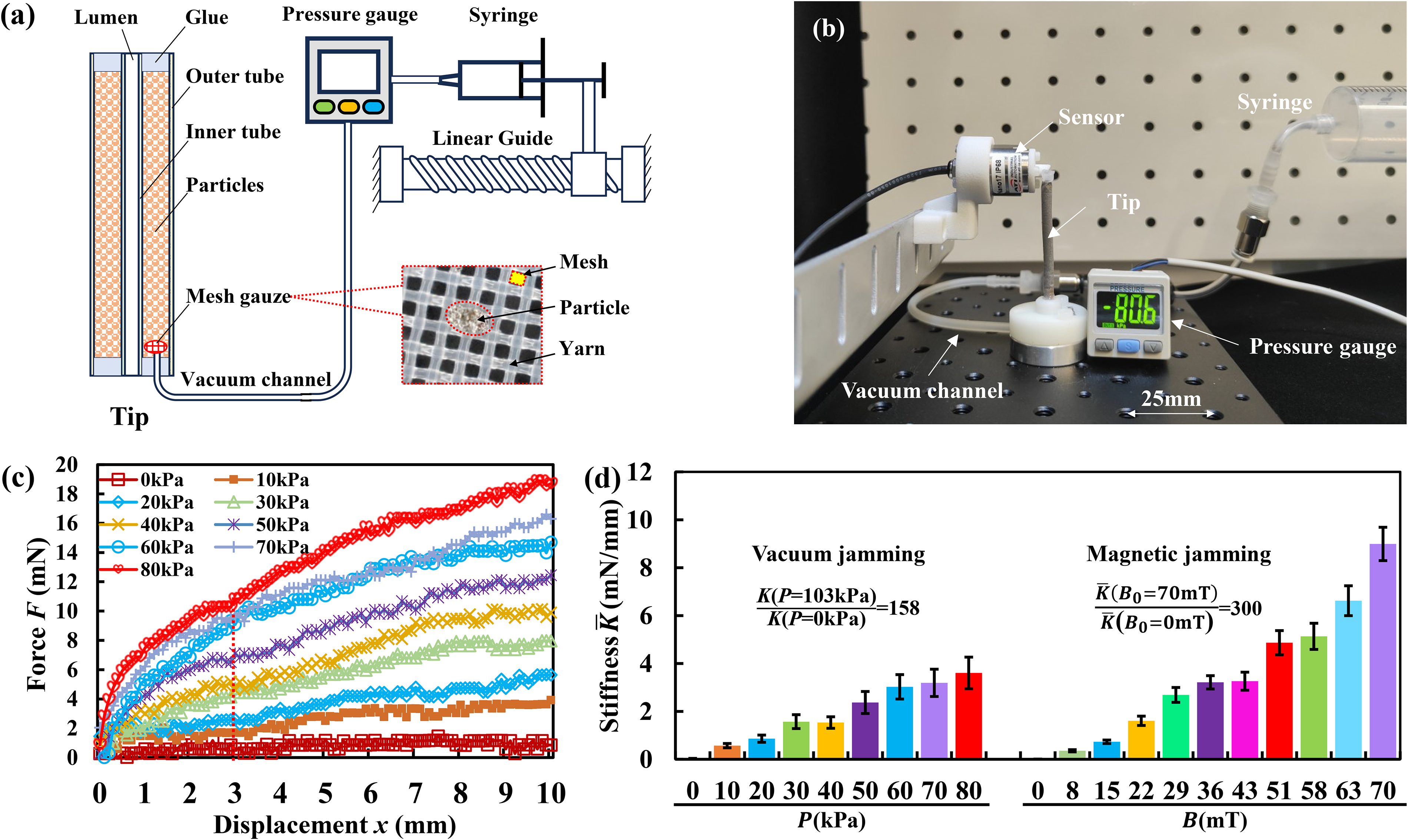
According to the definition of stiffness, here we measured the force-displacement curve and took its secant slope as the tip stiffness. The experimental setup includes a customized Halbach array-based magnetic actuation system, 73 a force sensor (ATI Nano17), and a linear guide (Fig. 4a). The magnetic actuation system 73 (Fig. 4b) comprises two layers of concentric, nested cylindrical Halbach permanent magnet arrays, capable of rotating freely relative to each other. These two layers of arrays are engineered to generate equal magnetic fields within the magnetic cavity. When superimposed in opposite directions, the resulting field becomes zero; when aligned, it reaches its maximum value; and when rotated synchronously, the direction can be adjusted. The hollow magnetic cavity has a diameter of 180 mm and a height of 240 mm. By shrinking the hollow cavity relative to its geometric center to a cylindrical region with a diameter of 175 mm and a height of 175 mm, this region serves as the working space. Within this working space, a uniform magnetic field is achieved, and the magnetic induction can be continuously adjusted from 0 to 80 mT. This benchtop-scale magnetic actuation system is designed primarily for catheter testing and small-scale phantom experiments. Its working space fully satisfies the spatial requirements of the experiments described in this study. The magnetic tip was deflected by the force sensor along the x-axis (Fig. 4c). The force sensor was installed on a motorized linear guide and driven with a 10 mm stroke at a speed of 1 mm/s. The force on magnetic tip can be accurately read from force sensor. Three experimental trials were performed for each testing condition to obtain the average value. Default parameters of magnetic catheter are listed in Table 1.
Stiffness tests of magnetic catheter.
Three groups of single-factor experiments were designed to validate the stiffness model of the magnetic catheter (Figure 5 a∼c). The influencing factors include combination of tube thickness, particle size, and magnetic induction. To better understand and compare the influence of these factors, we intercepted secant stiffness of all these force-displacement curves at x = 3 mm, and then arranged them in Figure 5d. We selected 3 mm as the reference deflection point for calculating stiffness because this value represents a conservative upper bound for the maximum tip displacement expected when the catheter functions as a stable platform in hepatic and splenic arteries (target diameters typically 4–7 mm). Since stiffness decreases with increasing deflection, selecting 3 mm avoids overestimation that would occur in the small-deflection region (where stiffness is higher), thereby providing a greater performance margin for real-world clinical use.
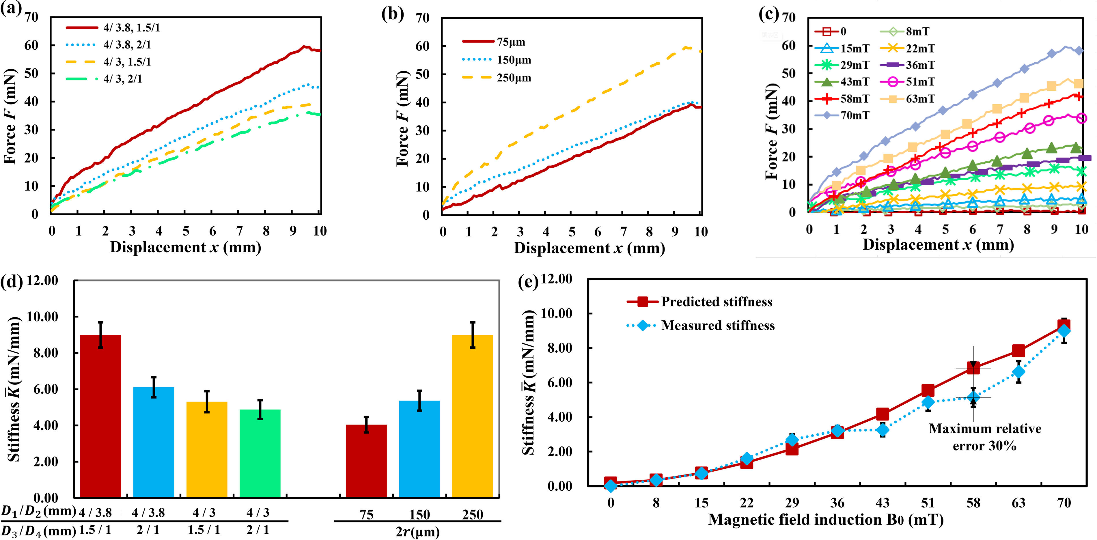
Stiffness tests of magnetic catheter. The default combination of tube diameter, particle size, and magnetic induction is respectively (4 mm/3.8 mm, 1.5 mm/1 mm), 250
In Figure 5d, the first group of data demonstrates the dependence of tip stiffness on the combination of diameters (
The second group of data studies the influence of particle size on the tip stiffness. Three kinds of particles with the diameter 2r at 75
The third dataset records how stiffness varies with magnetic induction. Eleven field levels were tested,
Benchmarking stiffness performance of magnetic jamming with vacuum jamming reference
The embedded magnetic particles in the tip enable both magnetic jamming under an external magnetic field and vacuum jamming under negative pressure. In this section, while preserving the tip’s magnetic steering capability intact, we fabricate an analogous vacuum-jamming variant under strictly identical conditions to benchmark the performance of these two VS mechanisms.
For the vacuum-jammed magnetic steerable tip, the material, particle type and size, filling fraction, shape, and geometric dimensions are exactly the same as those of the magnetic tip, ensuring that magnetic steering functionality remains fully intact. The only difference is that stiffness is modulated by vacuum negative pressure rather than an external magnetic field. Figure 6a and b illustrates the structure of the vacuum-jammed tip. Two concentric soft tubes were sealed at both ends with adhesive. Particles were filled into the annular space between the tubes. A vacuum channel was connected to the tip and a pressure gauge. To prevent particles from entering the vacuum channel while allowing air passage, a mesh gauze (mesh size 75
Benchmarking stiffness performance of magnetic and vacuum jamming.
Force-displacement curves under nine negative pressure values are shown in Figure 6c. The corresponding stiffness values calculated at x = 3 mm are presented in Figure 6d and compared with the stiffness results of magnetic jamming from Figure 5e. As negative pressure increases from 0 to 80 kPa, stiffness rises linearly from 0.03 to 3.61 mN/mm. The linear fit is
Under the same particle and geometric conditions, magnetic jamming achieved a stiffness increase from 0.03 mN/mm to 9 mN/mm at 70 mT, corresponding to a stiffness ratio of 300. This places magnetic jamming on the same order of magnitude as—and slightly higher than—the vacuum-jamming benchmark. These results, obtained under strictly identical particle and structural conditions for both mechanisms, demonstrate the effectiveness of magnetic interparticle interactions for achieving substantial VS in miniature steerable catheters.
The observed stiffness ratios are specific to the chosen particle size (2̃50 m) and miniature tubular geometry (OD 4 mm, length 50 mm). While optimal particle parameters would likely differ for each mechanism due to their distinct physical principles—vacuum jamming often scales more efficiently with smaller particles that provide higher contact density. This side-by-side demonstration under identical conditions still serves to validate the robustness of magnetic jamming as a cable-free alternative. Note that these results do not claim superiority of one mechanism over the other, since vacuum jamming typically scales more efficiently with smaller particles.
Validation of the static deflection angle and steering torque
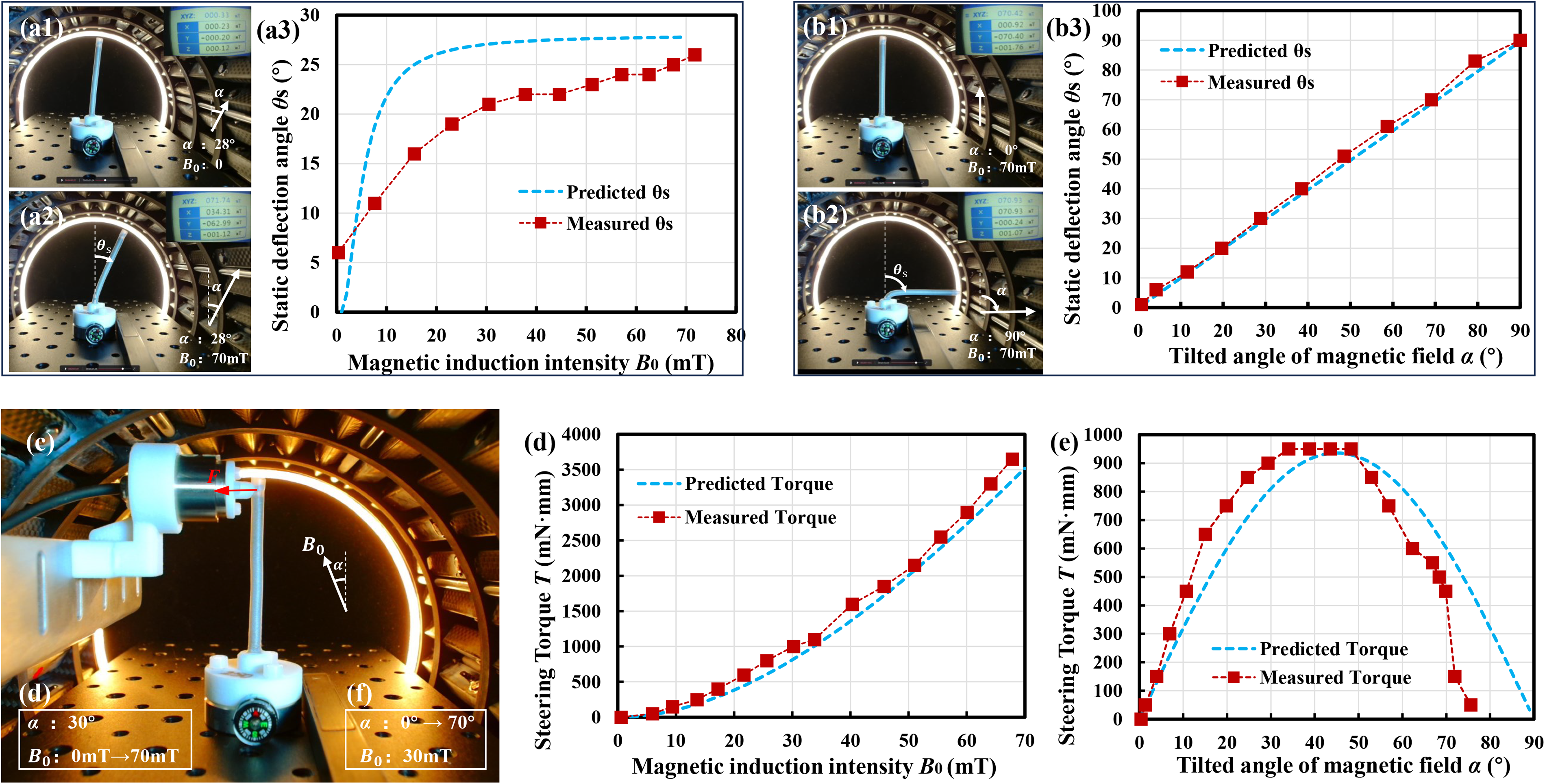
According to Eq. (17), magnetic induction
Static steering model test.
In Figure 7a2 or b2, when tilted magnetic field was applied, the rotation of tip was completed in an instant.
All particles in the same chain within the magnetic tip experience essentially identical magnetic torques at any instant, leading to simultaneous and coherent rotation along the chain without requiring frictional coupling for synchronization. Combined with the fixed proximal boundary, the tip behaves as a nearly rigid body. As shown in Figure 7, the entire tip exhibits stiff overall rotation with deformation localized at the base, which agrees with the measured tip angle versus magnetic field strength/direction curves and the in-situ images.
Performance demonstration for magnetically jammed steerable catheter
Prototype and bending test
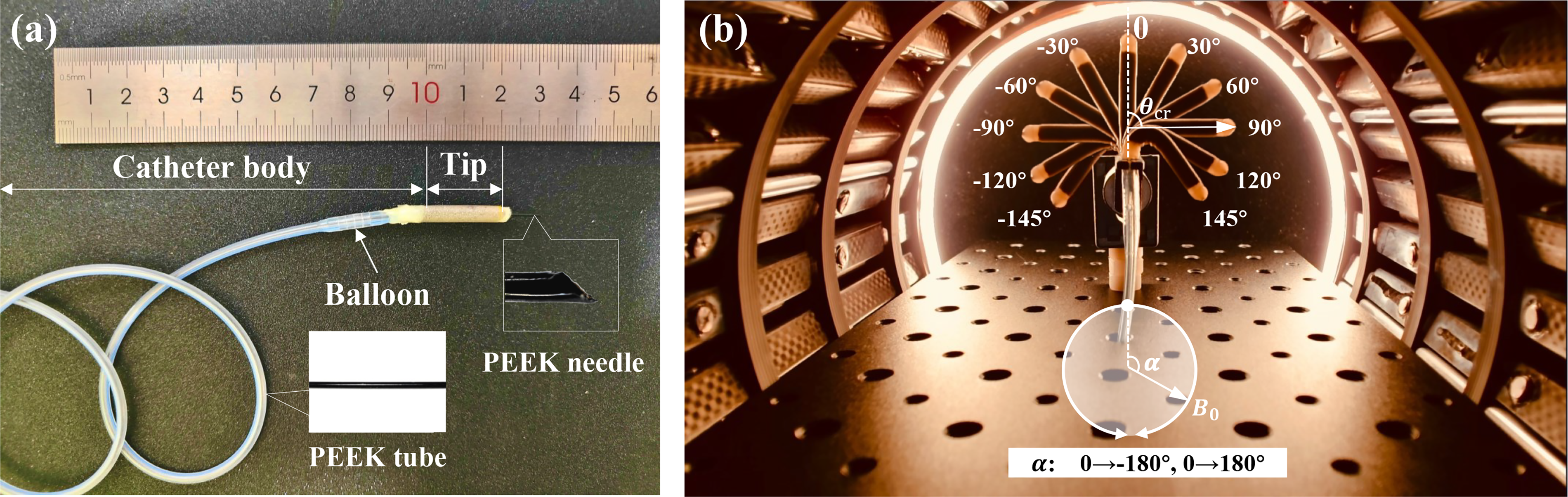
The fabricated magnetically jammed steerable catheter prototype is shown in Figure 8a. It mainly consists of a magnetic tip (OD/ID 4 mm/1 mm, length: 20 mm) and a catheter body (OD/ID 2.7 mm/1 mm, length: 32 mm). The PEEK tube running through the whole catheter has an OD of 0.7 mm and a thickness of 0.1 mm. The silicone tubes and magnetic particles follow the parameters specified in Table 1, except that the length L is changed from 50 mm to 20 mm to ensure minimal invasiveness. The magnetic tip underwent continuous bending driven by a rotating magnetic field of
Bending test.
VS test
The magnetic tip was fixed along horizontal direction. Then, a horizontal magnetic field

Deflection of magnetic tip under different weights and magnetic induction intensities (the tip length of 20 mm can be treated as a scalar bar).
Magnetically steered VS catheter enabling Fine-Needle aspiration of vascular tumors
To demonstrate the active steering and VS performance of the magnetic catheter in human environment, we employed a multibranched silicone vessel phantom (Fig. 10a) that simulates the branching path and tumor of the hepatobiliary system. We use “Sub” to refer to 1st-level branches and “SSub” to refer to 2nd-level branches. Four 1st-level branches, Sub 1–4, emerge from the main trunk. Among them, Sub 1 has one 2nd-level branch (SSub 1.2), while Sub 2 has two 2nd-level branches (SSub 2.1 and SSub 2.2).
Demonstration of the active steering and variable stiffness function of the magnetic catheter in FNA. 
At the distal end of Sub 2, there is a suspected tumor-like mass causing complete obstruction of the lumen. The lesion appears as a solid, bulky proliferative tissue filling and occluding the distal segment of Sub 2, with relatively smooth surface and indistinct borders from the surrounding ductal wall. The catheter is advanced from the main trunk, passes through bifurcation ② into Sub 2, and reaches the site of complete obstruction. Due to the firm consistency of the obstructive mass, direct straight puncture is difficult, requiring rotational maneuvering of the needle to successfully penetrate and perform fine-needle aspiration (FNA) sampling of the obstructive proliferative tissue.
To achieve active steering at vascular bifurcations, our operational protocol is divided into the following three scenarios and displayed in Supplementary Video S2:
Navigation in curved vessels: The tip was inserted into the main trunk (Fig. 10b1). Then, a 30 mT magnetic field was applied along the axis of the magnetic tip to prepare for steering while maintaining the relative flexibility of the magnetic tip. When the catheter moved forward, the external field direction was rotated ahead of the current tip axis to generate sufficient torque (Fig. 10b2, b3), overcoming the tip’s elastic resistance and frictional forces from the vessel wall, thereby guiding the tip to align with the vessel path or enter into the desired bifurcation. VS at the target site: When the magnetic tip arrived at the target tumor-like mass, to achieve high stiffness for stable surgical manipulation without displacing the catheter tip, the over-rotated external magnetic field direction was aligned coaxially with the current magnetic tip axis first ( For tumor-like mass puncture, with VS enabled, after balloon anchoring and increasing magnetic induction to lock the tip orientation, the puncture needle could be advanced while maintaining stable tip position and achieving successful insertion (Fig. 10b7). In contrast, without VS capability (i.e., Withdrawal: The balloon was deflated,
Discussion
Justifications for using soft magnets as jamming materials
According to hysteresis characteristics, magnetic materials can be classified as soft-magnetic, hard-magnetic, and superparamagnetic.
79
Soft-magnetic materials exhibit low coercivity (
The magnetic hysteresis loops of six soft-magnetic powders were measured using a vibrating sample magnetometer (Supplementary Fig. S2), with key magnetic parameters extracted and summarized in Supplementary Table S1. All six materials exhibit very low remanence magnetization (
Comparison of our work with MR fluids and soft magnetic pillar jamming
We propose a carrier-free, matrix-free design: using soft-magnetic powder directly as the jamming medium, encapsulated within concentric thin-walled tubes. An external magnetic field induces interparticle attraction and force-chain formation to realize reversible magnetic jamming. The advantages and improvements are as follows:
(1) High particle packing fraction and improved magnetic energy density: Without carrier liquid or resin matrix, soft-magnetic powder occupies the vast majority of the cross-section. Our scheme achieves a particle packing fraction of
Overall, the proposed “soft-magnetic powder + concentric thin-film tube” scheme provides complementary strengths relative to MR fluids and jamming with magnetic composites, particularly for applications requiring high magnetic energy density, compact integration, and reliable encapsulation within the stringent spatial constraints of robotic catheters.
Material biocompatibility
The catheter body was derived from a commercially available medical silicone balloon catheter (with the distal tip removed). The coaxial tubing for the elastic magnetic tip was fabricated using silicone rubber, a material that has been extensively reported in the literature for in vivo experiments and demonstrates excellent biocompatibility. The pure iron powder in the elastic magnetic tip is fully encapsulated within the silicone tubing. Since the current study is a dry in vitro benchtop experiment with no contact with bodily fluids, there is no risk of direct iron powder exposure. The tube running through the entire catheter was made of PEEK, a biocompatible high-performance polymer commonly used in minimally invasive catheters for its excellent mechanical properties and low friction. However, for future ex vivo/in vivo experiments and clinical translation, a comprehensive biocompatibility testing will be required—including cytotoxicity, sensitization and irritation, hemocompatibility, and degradation product analysis—to rigorously assess the long-term biocompatibility of the overall catheter.
Variable bending radius and distributed deformability
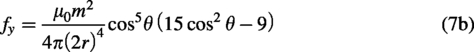
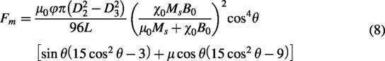
In the derivation of Eq. (8) and the static steering model test shown in Figure 7c, the field-induced restoring force
To further illustrate the practical advantages and distributed nature of the multiparticle design, we consider its performance in tortuous vascular environments. Safe navigation through vessels with numerous curvatures and bifurcations requires small, localized bending radii with minimal vessel wall interaction. A fixed root-hinge design results in a larger effective turning radius equal to the rigid segment length, increasing the risk that the sharp tip will impinge on or perforate the outer vessel wall during advancement at bifurcations (Fig. 11a). In contrast, the proposed multiparticle jammed tip enables steering at arbitrary locations along its length, allowing tighter local curvatures and significantly reduced invasiveness, which is particularly advantageous in narrow or branched vessels (Fig. 11b).
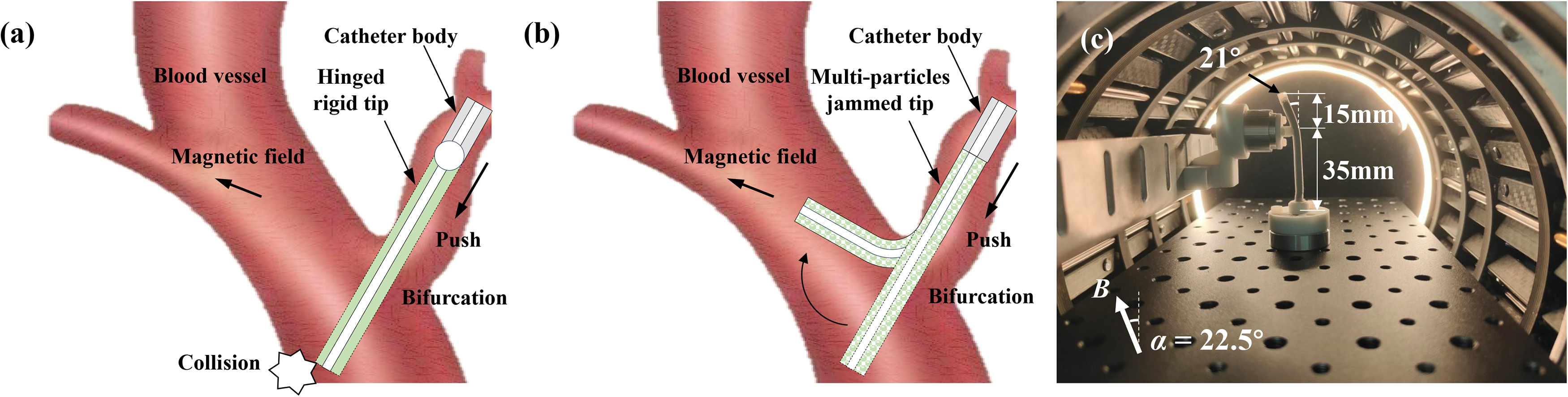
Demonstration of distributed deformability and navigation advantage of the multiparticle jammed magnetic tip.
To more directly demonstrate the distributed degrees of freedom, an additional supporting experiment was performed in which the lower 35 mm of the 50 mm tip was mechanically constrained using a measuring probe, while only the upper 15 mm was subjected to a rotating magnetic field (Fig. 11c). The upper segment follows the magnetic field and bends independently at a variable angle (e.g., 21°), allowing localized deformation and tunable bending radii. This behavior, enabled by interparticle rotation, would not be possible with a rigid hinged rod, where deformation is strictly limited to the hinge point.
The multiparticle design therefore provides distributed deformability with variable bending radii, allowing the tip to accommodate complex loading conditions encountered during surgery. Although surgical tools (such as grippers, needles, or coils) can exert various forces including bending, torsion, and compression on the tip, we focused our characterization on lateral stiffness—the mode that produces the largest deformation and represents the weakest link. If this critical (weakest) lateral stiffness satisfies the stability requirements in surgical operations, the tip is expected to perform adequately under other loading modes as well.
Interparticle interactions, chain elongation, and boundary effects
While the VS model focuses on the macroscopic force-deflection response of the catheter tip under external loads and applied magnetic fields, the following discussion examines internal interparticle interactions—including repulsive forces between particles and their influence on the confining tube boundaries—demonstrating that the resulting thrust is negligible.
In a two-particle system, a repulsive component indeed exists when the angle between the particle connection line and the magnetic field exceeds ∼54.7° (Fig. 3c). However, the situation becomes somewhat different in a three-particle system. For example, consider particles 1 and 2 aligned along the magnetic field direction, with particle 3 positioned symmetrically with respect to particles 1 and 2, as shown in Figure 12a, b. Let
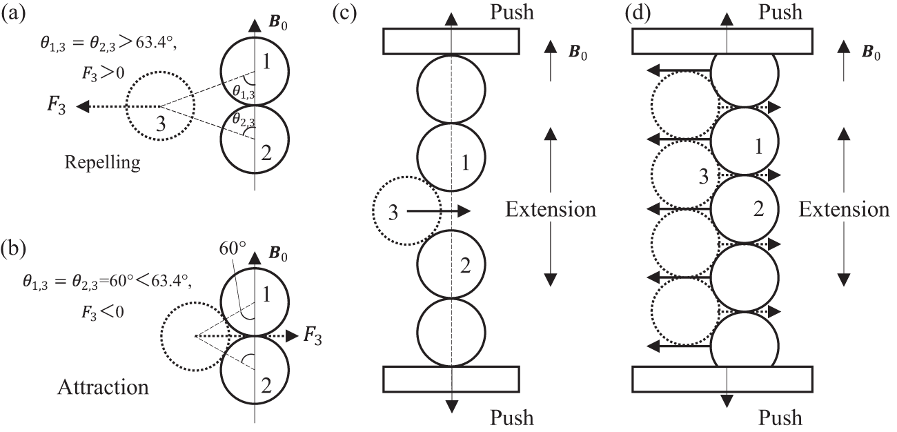
Interparticle interactions in magnetic chains.
If particles 1 and 2 belong to a single chain, the chain absorbs particle 3 and tends to elongate along the magnetic field direction, as shown in Figure 12c. If particle 3 in Figure 12c belongs to another single chain, then the two closely spaced chains tend to absorb each other, elongate along the magnetic field direction while contracting orthogonally to it (Fig. 12d). For the elastic magnetic tip in this article, the application of an axial magnetic field results in thrust at both ends of the tip, a phenomenon that has been previously reported in the Refs.60,85 By substituting the volume fraction of 52.3%, a magnetic induction
Scalability challenges and prospects for clinical application of the Halbach array
For clinical applications of the Halbach array—to accommodate the head, limbs, or even the torso—the inner diameter would need to increase to ∼600 mm (comparable to the bore size of commercial clinical MRI systems). It should be noted that the customized Halbach array is only our choice of magnetic actuation system for benchtop robot testing and validation in this study; it is not presented as a major contribution of this work. Scaling the current 180 mm inner diameter system to 600 mm while maintaining a uniform 0–80 mT field would introduce substantial engineering challenges, including significantly increased system size and weight, heightened assembly complexity due to stronger inter-magnet forces, and greater torque requirements for mechanical array rotation.
Other magnetic actuation approaches, such as superconducting magnets or large-scale electromagnetic coils used in clinical MRI systems (e.g., 1.5–3T whole-body MRI scanners with bore diameters of 6̃00 mm), have successfully achieved strong uniform magnetic fields at human scales and are routinely used in clinical settings. Additionally, permanent magnet-based systems like the Stereotaxis Niobe magnetic navigation system 86 —which generates uniform fields up to 80 mT in a workspace suitable for cardiac catheter procedures and has been FDA-approved for clinical use since 2002—further demonstrate the feasibility of high-intensity field generation using nonelectromagnetic approaches in human-scale applications. These systems demonstrate that generating high-intensity uniform fields for human-scale applications is technically feasible with established engineering solutions.
Nevertheless, a key advantage of our pure permanent-magnet Halbach array design is that field generation and maintenance require no continuous current input, eliminating the high-power consumption and severe thermal dissipation issues typical of electromagnetic coils. The motors consume only modest energy during field adjustment via array rotation, providing excellent energy efficiency, thermal management, and safety.
The current benchtop Halbach array is sufficient for the catheter testing and small phantom validation reported in this study. For future clinical applications, we believe that optimizing the array geometry and arrangement 87 —for example, increasing the azimuthal segmentation number, which can reduce relative rotational resistance between the layers and enlarge the working space within the same magnetic cavity—as well as employing higher-performance rare-earth permanent magnets and scaling up the array, offers viable pathways to meet human-scale requirements.
Comparison with other VS methods in catheter
VS strategies for medical catheter or endoscopy can be broadly grouped into: (1) thermally driven phase-change or shape-memory materials (e.g., PET, bioplastic material, SMPs, low-melting-point alloys, LMPAs), (2) pressure-driven jamming (inflation and vacuum jamming), (3) mechanically interlocked structures (e.g., rotating coaxial tubes, tendon antagonism, magnetically actuated mechanical locking), and (4) field-driven granular jamming (this work: magnetic jamming). We compare them along stiffness ratio, response time, controllability, integration burden, and safety, using the quantitative data summarized in Table 2.
Comparison of the Proposed Magnetic Jamming with Other Variable Stiffness Methods Applied in Medical Soft Continuum Robots
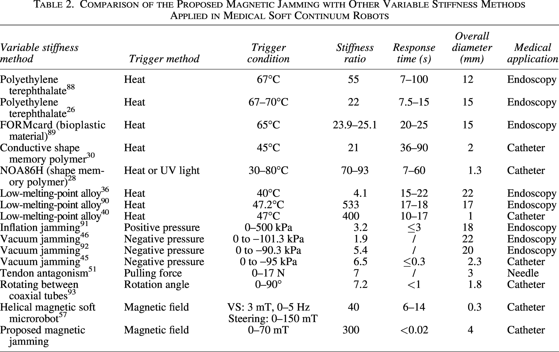
Stiffness ratio. Heat-based LMPA methods report the highest ratios, reaching 533 and 400 in prior studies, with other thermally driven materials typically 21–93 (e.g., PET 22–55, NOA86H 70–93, conductive SMP 21). Pressure-based jamming ranges from 1.9 to 6.5 depending on vacuum level and geometry, while mechanically interlocked structures (e.g., rotating coaxial tubes) achieve about 7.2. Recent helical magnetic soft microrobot approaches reach 40-fold. Our magnetic jamming attains a ratio of
Response time. Thermally driven materials generally require seconds to tens of seconds due to heating and cooling (e.g., PET 7–100 s, bioplastic material 20
Controllability. Phase-change approaches often exhibit steep modulus transitions within a narrow temperature window, resulting in switch-like behavior that hinders fine mid-range tuning. In contrast, pressure-driven, mechanical interlocking, and both magnetically actuated mechanical locking and magnetic jamming provide continuous, monotonic control via analog inputs (pressure, rotation angle, or magnetic frequency/induction). Notably, a recent helical magnetic soft microrobot achieves fully decoupled control of stiffness tuning (via low-intensity rotating fields of 3 mT, 0–5 Hz) and active steering (via static fields up to 150 mT), enabling independent modulation without mutual interference. In our device, the stiffness–field relationship is smooth over 0–70 mT, allowing for effectively continuous adjustment with instrument-limited resolution—suited for on-the-fly modulation during catheter alignment.
Integration and scale. Many heat-based approaches require heaters, temperature sensors, and sometimes cooling pathways, increasing system volume (overall diameters in the literature 1–22 mm). Vacuum/pressure jamming needs airtight bladders and tubing; compactness depends on pumps and seals (OD 2.3–22 mm in Table 2). Mechanically interlocked structures typically range 1–3 mm. A recent helical magnetic soft microrobot achieves the smallest reported diameter (0.3 mm) by integrating with commercial microcatheters. The proposed magnetic jamming integrates a compact particle chamber with a small field source, currently at 4 mm overall diameter, with potential for further reduction through thinner microtubing.
Safety and energy. Thermal methods risk local overheating and unintended abrupt stiffness changes near the transition temperature, especially adjacent to fragile tissues. Pressure-driven jamming avoids heat but introduces pneumatic leakage and seal reliability concerns. Both helical magnetic soft microrobot and magnetic jamming avoid thermal load and use only low-intensity magnetic fields; ferromagnetic components can be biocompatible when properly encapsulated. Field generation shifts safety focus to magnetic exposure limits, which can be engineered within regulatory guidelines.
In summary, while thermally driven LMPA remains the benchmark for peak stiffness ratio and recent helical magnetic soft microrobot excels in extreme miniaturization (0.3 mm), magnetic jamming provides a favorable balance of very high stiffness ratio (
Conclusion
In this article, a novel magnetic jamming method allowing VS and active steering is proposed for a robotic catheter.
A single-source magnetic particle jamming approach was proposed, addressing the limitations of current magnetically steered VS catheters, which rely on dual sources for steering and stiffening—leading to compromised efficiency, increased cross-sectional footprint, and safety risks such as heat generation, pressure, and antagonistic forces. Our approach leverages a carrier-free, matrix-free magnetic jamming scheme, utilizing soft-magnetic powder as the sole jamming medium, directly encapsulated within coaxial thin-walled tubes. This design enables higher particle volume fraction, easier miniaturization, and reduced leakage risks compared to alternative techniques. Through a single magnetic input, it achieves integrated, reversible control of both catheter tip steering and stiffness modulation, providing an efficient, compact, and safer solution for the catheter. A stiffness model and a static deflection model of the magnetic tip are established analytically and validated experimentally. The influencing factors on stiffness and steering angle are determined, including tube parameters ( The VS level of magnetic jamming is evaluated. It reaches 300-fold stiffness modulation (high stiffness ratio), subsecond adjustment (fast response), and continuous infinite-level control (precise tuning). The developed prototype of the magnetic catheter reaches the steering range of
At present, we have completed the in vitro experiment to verify the feasibility of our magnetically jammed steerable VS catheter for our target application. In the future, we will further reduce the catheter tip to the submillimeter level and expand its applications to other challenging endovascular interventional procedures.
Footnotes
Author Disclosure Statement
No competing financial interests exist.
Funding Information
Research reported in this work was supported in part by the
Supplemental Material
Supplemental Material
Supplemental Material
References
Supplementary Material
Please find the following supplemental material available below.
For Open Access articles published under a Creative Commons License, all supplemental material carries the same license as the article it is associated with.
For non-Open Access articles published, all supplemental material carries a non-exclusive license, and permission requests for re-use of supplemental material or any part of supplemental material shall be sent directly to the copyright owner as specified in the copyright notice associated with the article.