
Abstract
This article presents a dynamics-based path-planning framework for tensegrity robots that accounts for environmental interaction. A systematic investigation is conducted into the mapping among locomotion gaits, actuations, and ground interaction forces of a six-bar tensegrity robot. The study addresses three coupled challenges within a unified framework: the dynamic effects of flexible-body deformation and environmental interaction, the construction of a finite gait library for realizing discrete motions, and a dynamics-informed local path-planning strategy for varying contact and friction conditions. A general dynamic model is established to describe contact friction and generate interaction-aware gaits. Subsequently, a gait library is developed that maps sequences of gait primitives to commanded motions. A lightweight local planning strategy, denoted as M1L2T3, is then formulated on this gait-primitive graph to enable efficient path selection under local map information. A proof-of-concept prototype is fabricated for experimental validation. Experimental results confirm the effectiveness of the interaction-coupled dynamic model for gait generation and locomotion control, showing reasonable agreement with theoretical predictions and validating the proposed planning strategy. The results demonstrate the value of incorporating interaction-aware gait realization into locomotion planning for tensegrity robots.
Keywords
Introduction
Planetary surface exploration requires mobile robots capable of tolerate impact, adapt to uncertain terrain, and operating under constrained sensing and computational resources.1–3 Conventional wheeled or rigid-body robots perform well on regular terrain, but they often perform poorly when support conditions are discontinuous and contact transitions are frequent. 4 In such environments, compliant and reconfigurable robots offer distinct advantages.5–7 Locomotion tensegrity robots (LTRs), composed of compressive bars and tensile cables, offer low weight, impact tolerance, and geometric adaptability. 8 These attributes make LTRs promising for exploration across varying terrain, where contact robustness is as critical as nominal motion efficiency.9–11
Among tensegrity locomotion platforms, six-bar LTRs have been studied extensively because they balance structural symmetry, locomotion diversity, and actuation feasibility.12,13 Previous works have demonstrated rolling, flipping, and multigait locomotion14,15 using either cable- or bar-driven actuation. This body of work clarifies the roles of topology, symmetry, and gait generation. However, most prior studies have focused primarily on gait realization. The displacement achieved by each gait is still often described at an idealized kinematic level.
From a mechanics perspective, models for six-bar LTRs exist at several levels of abstraction. Simplified kinematic 16 and gait-level 17 models are effective for problems such as form-finding,18–20 gait switching, 21 and analyzing support transitions. 22 However, they are less suitable when locomotion is strongly affected by structural deformation and environmental interaction. Tensegrity systems exhibit highly nonlinear behavior arising from geometric constraints, prestress, and coupled bar–cable interactions. 23 Dynamics-based modeling is therefore more appropriate when the goal is to predict the actual execution of a gait, not just its nominal motion. Reduced-order24,25 and multibody approaches, including Newton–Euler26,27 and Port–Hamiltonian 28 formulations, offer compact descriptions but often do not fully capture distributed deformation and local friction effects. For contact-rich locomotion, flexible-body, 29 beam-based, 30 and contact-friction-aware formulations 31 are more suitable, as they can better describe deformation, 32 contact-state switching,33,34 and environment-dependent interactions. In particular, the absolute nodal coordinate formulation (ANCF) 35 is attractive for tensegrity systems with complex cable–bar connectivity because it uses global coordinates, yields concise governing equations, and supports a clear computational procedure. For this reason, this work adopts an interaction-aware ANCF dynamic model to predict gaits.
From a planning perspective, works on six-bar LTRs have mainly addressed gait-sequence design,36,37 rolling direction selection, 38 and path planning39,40 based on predefined kinematic primitives. More advanced approaches, such as model predictive control41–43 and learning-assisted locomotion,44–47 have also been explored for tensegrity systems. Some contact-aware planning26,43,48 studies further consider terrain interaction. However, these methods often require substantial online optimization or considerable offline effort. The present work targets a different scenario: resource-constrained exploration with only local map information and limited onboard computation. Under these constraints, a lightweight and usable local strategy is more suitable than a computationally intensive real-time scheme. A programmable gait library, combined with a local heuristic planner, therefore provides a practical way to connect planning with interaction-aware gait realization.
Figure 1 illustrates this underlying motivation. Different planetary grounds may exhibit varying frictional properties, meaning locomotion cannot be separated from environmental interaction. Figure 1b–e shows a six-bar LTR moving in an environment containing obstacles. If path planning is built only on kinematic gaits, the robot may collide with obstacles or fail to reach its goal. In contrast, planning based on interaction-aware gait realization can guide the robot more reliably to the destination under the same safety envelope. This mismatch provides the motivation for the present framework. The key issue is that a kinematically planned gait may not match the actual realized gait under frictional interaction and contact switching. Therefore, path planning is reliable only when it uses sufficiently accurate gait predictions. At the same time, for resource-constrained planetary exploration, the planning method should remain lightweight and computationally efficient. These dual requirements motivate the present framework, which combines interaction-aware gait modeling with a low-computation local planning strategy. Despite recent progress, an integrated framework that addresses these coupled requirements in a consistent, practical manner is still lacking.
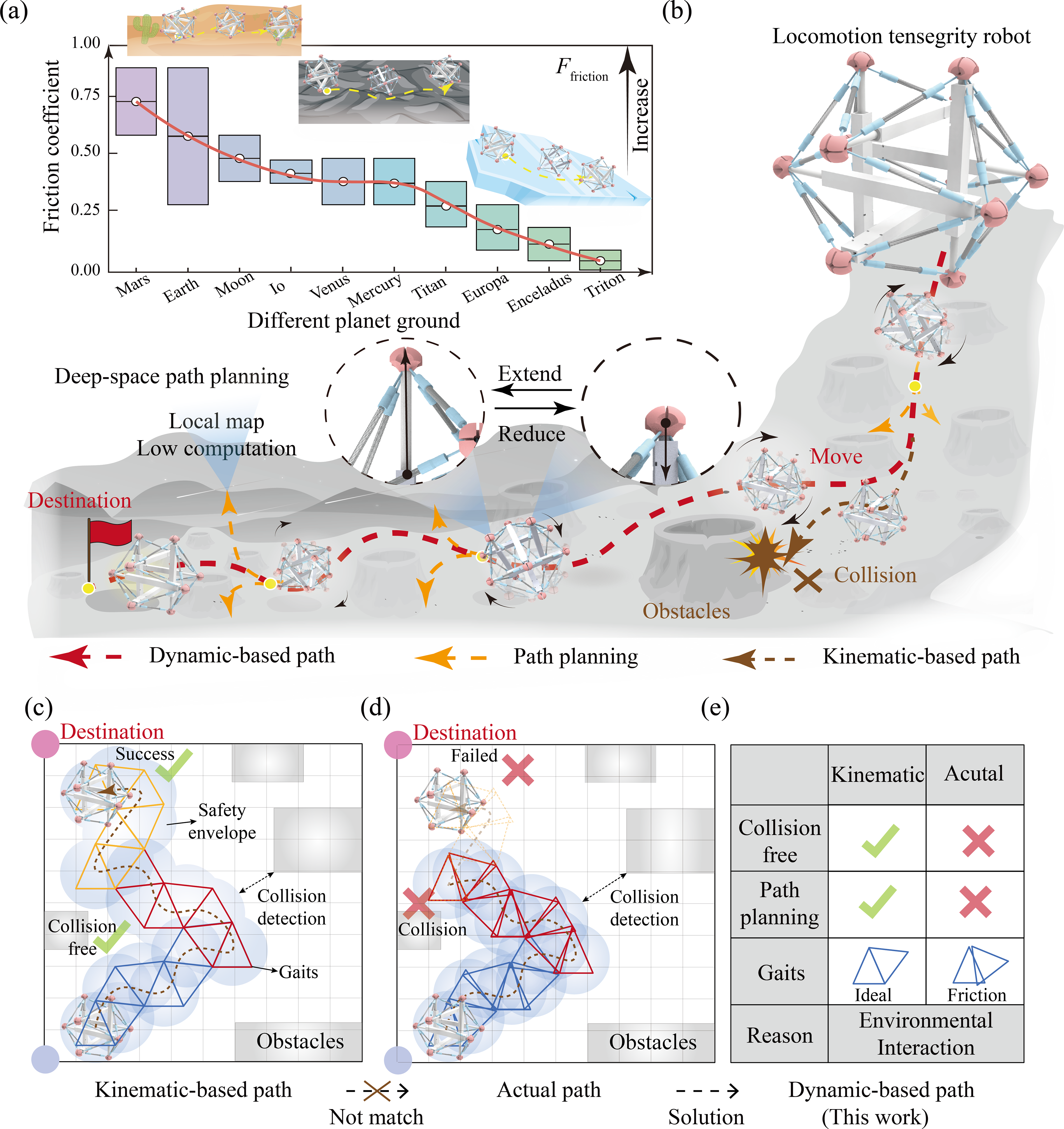
Motivation of interaction-aware path planning for a six-bar locomotion tensegrity robot.
Motivated by this gap, this article develops a dynamics-based locomotion planning framework for a six-bar LTR. First, a dynamic model is established that describes the robot with flexible bars, ground contact, and friction, enabling the prediction of realized discrete gait outcomes. Second, the relationship between actuation and locomotion is abstracted into a finite gait library of interaction-aware discrete motion primitives. Third, based on this gait set, a lightweight local planning strategy, termed M1L2T3, is formulated for path selection under local-map constraints and limited computational burden. The proposed approach is evaluated through simulations and experiments with a prototype on several representative ground surfaces with different friction conditions. The central contribution of this work is not a new class of path planners, but rather a method to improve planning–execution consistency by integrating interaction-aware dynamic gait primitives into the planning framework.
Dynamic Modeling Considering Environmental Interaction
Configuration and mechanism of the LTR
The LTR consists of 6 bars and 24 cables in Figure 2. The bars form an icosahedron-like structure, and each bar is realized as an electric linear actuator with driving and driven parts. The cables enclose several equilateral and isosceles triangles. The configuration should satisfy static equilibrium after assembly.
49
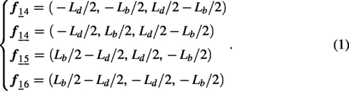
We label the six bars as bar i and use ni to express the ith node. An underline is used to differentiate between endpoints of the bars. For arbitrary node n
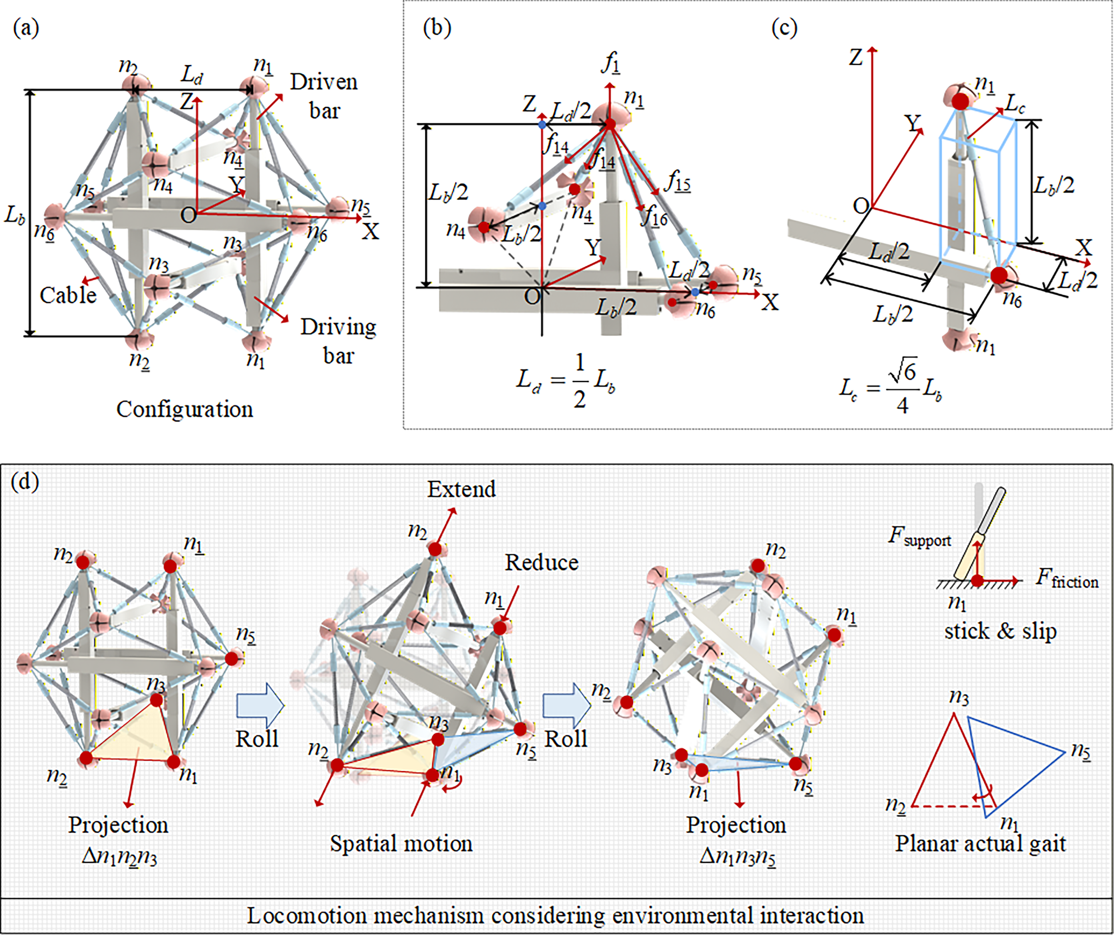
Configuration and locomotion mechanism of the six-bar locomotion tensegrity robot (LTR).
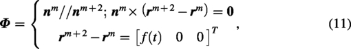
The total resultant force is

Given that the direction of the force f
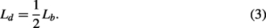
Figure 2c illustrates the relationship between the bar and the cable length. For the diagonal of a rectangular cuboid, we have

Locomotion is generated by changing bar lengths. Starting from a state where the open triangle Δn1n
A multibody modeling method with contact and friction
An ANCF 3D high-order beam element (Fig. 3a, b) based on the inertial frame is used for modeling.33–35 The coordinates

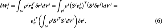
Interaction-aware dynamic modeling of the LTR.
where

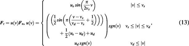
The member under LTR is an electrostrictive telescopic bar. The relative motion direction of the two components is along the axial direction
The external force

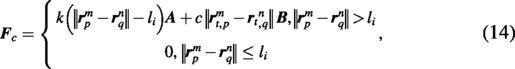
Cable forces are modeled through a Kelvin–Voigt-type relation. The cables are treated as tension-only elements, so they cannot carry compressive loads. If the computed cable force becomes compressive, its contribution is set to zero in Eq. (14). Sliding at the cable attachment points is neglected, as the spring ends are connected to fixed bar-end interfaces rather than allowed to slide along the bars.
As the ith cable is used to connect the mth and nth nodes on the pth and qth bars, the force exerted by the cables can be expressed as:
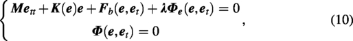
By adding up the external forces generated by Eqs. (12)–(14), and according to the FEM assembly procedure, the final dynamic equation of the LTR considering the environmental interaction can be derived as
This nonlinear system is solved by the generalized-α method, which provides good numerical stability and accuracy for highly nonlinear flexible multibody dynamics.31–33 The detailed derivation and solver procedure are given in the Supplementary Data.
Mathematical Descriptions of Discrete Locomotion Gaits
This section addresses three questions. First, how can the locomotion of the LTR be described in a discrete and programmable way? Second, how do these discrete gaits relate to path generation under different interaction conditions? Third, how does friction affect the realized gait geometry?
The prediction and analysis of the locomotion gaits and the actuation
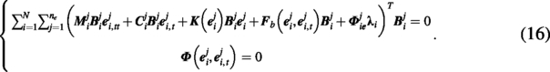
Using the parameters listed in Supplementary Table S2, a cable pretension of 10 N is applied to maintain structural stability during rolling. In Figure 4a, nodes n1, n

Dynamic gait realization and construction of the discrete gait library.
Figure 4c, d illustrates the variation of COM. Due to the interaction, the path of COM exhibits slight nonsmooth curves. Figure 4c shows that the vertical position of the COM remains nearly constant, and the two consecutive locomotion result in a net displacement toward the first quadrant. Figure 4d depicts the ground-contact triangle during locomotion. The pair of moments formed by the force of the COM under gravity and the interaction force between the triangular support nodes and the ground is the primary mechanical cause of the locomotion.
The six-bar LTR comprises eight equilateral and 12 isosceles triangles. Each equilateral triangle admits three possible rolling directions, whereas each isosceles triangle admits two. A matrix
Environmental interaction induces both stick–slip motion and local rotation of the support-triangle projection, which makes the realized path less predictable than the nominal kinematic description. However, the robot’s structural symmetry yields a useful rolling regularity. After four steps, and neglecting small perturbations, the grounded triangle returns to a support class equivalent to the initial one but translated in space, as shown in Figure 4f. This property allows the locomotion to be organized into a finite and programmable gait library, as shown in Figure 4g.
Figure 4h shows a summary of the paths of these 12 basic gaits. The X and Y of any basic gait will only have three sizes: 0, lx, and ly. The LTR can perform programmable locomotion of each path under the permutations of the gait library. Although four potential blind spots are identified in the planning stage, they are covered by the robot’s body envelope and thus do not constitute actual unreachable regions, as discussed in Supplementary Figure S4. One remaining aspect to be understood is the actual impact of environmental interaction on LTR.
The gait library in this work is manually curated based on the symmetry and repeatable support-transition characteristics of the six-bar LTR. It therefore provides a finite and discretized motion representation, rather than a universal basis for motion. More automatic or learning-based gait generation is a promising future direction for improving scalability, but it would require substantially more data, calibration, and validation.
A key condition enabling this finite gait library is rolling symmetry: after a complete sequence of discrete rolling steps, the robot returns to an equivalent support-triangle class with a pure positional translation and no net orientation change. This property holds for the six-bar LTR owing to its structural symmetry and repeatable support-transition pattern. This property not only justifies the construction of a finite gait library from a limited set of primitives but also provides a potential guideline for extending the present framework to other tensegrity or reconfigurable robots that exhibit similar rolling symmetry.
Interactive effect coefficient determined by friction
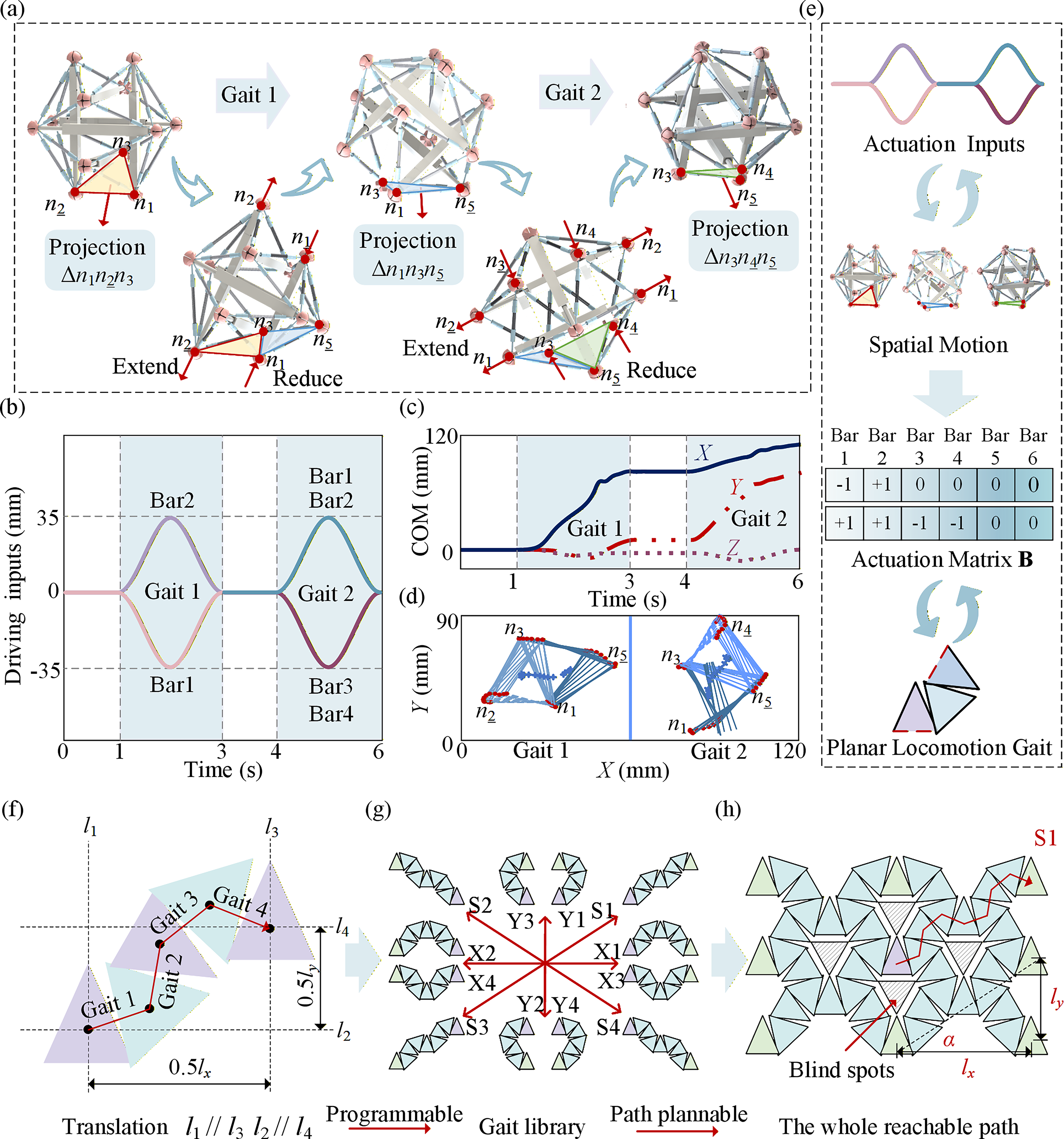
The locomotion is essentially resulted from the imbalance between the driving force and the ground friction, which leads to a shift of COM. The friction model in Figure 3f has four parameters: static and dynamic friction coefficients μs and μd, static and dynamic friction velocities vs and vd. For rapidly varying dynamic problems like LTR, the interaction effect coefficient is basically only related to μs. 37 Thus, vs = 0.1 mm/s, vd = 10 mm/s, and μd = 0.7 μs for simulation.
Figure 5a reveals that as μs increases, lx and ly exhibit corresponding and synchronous growth. Notably, comparisons of lx and ly for different μs reveal that the ratio between the moving lengths and friction coefficient is perfectly consistent. Figure 5b shows that the red nodes lie along two straight lines, ly = (±1/3)05 lx. Interestingly, the gait from the kinematic analysis also lies on this line. When μs > 0.27, the slip phenomenon rarely increases in the subsequent gait. From this, it can be concluded that variations in μs result in a scaled version of the basic gait in terms of distance, without affecting the basic gait orientation. Supplementary Figure S4b also indicates that the geometric coverage of the gait library depends on the realized gait displacement under environmental interaction: lower-friction cases yield higher coverage ratios, whereas higher frictions increase the total cell area but reduce the relative reachable proportion of reachable cells.
Effect of friction on realized gait geometry.
Figure 5c and d compares representative locomotion paths under four different friction conditions. At low friction, a single gait execution mainly results in a shortened displacement. At moderately larger friction, the realized motion exhibits both shortening and rotation. These results confirm that the gait library must be constructed from interaction-aware gait outcomes, rather than purely kinematic ones.
Locomotion Path-Planning Strategy for Discrete Gaits
A lightweight receding-horizon gait planner on a gait-primitive graph
The planned path is generated by combining predefined discrete gaits from the gait library. Because the target application is resource-constrained exploration, the planner is designed to operate using only local map information and low online computational cost. Unlike global graph-search methods, the present planner performs local feasibility screening, short-horizon directional evaluation, and replanning after each executed primitive when sensing is available. A body-level safety envelope is introduced to represent the robot’s footprint for obstacle checking.
Inspired by this, a lightweight receding-horizon planner, named “M1L2T3,” is proposed. Figure 6a illustrates the locomotion with discrete gaits from the gait library based on local map information. Each circle represents its reachable point in the next gait, which is also the center of the triangle contacted with ground. Based on the gait analysis, the horizontal, vertical, and line distances between adjacent circles are lx, ly, and ls. For obstacle handling, a unified body-level safety envelope is adopted. Specifically, the robot is represented by a circular envelope centered at the support-triangle center, with a radius Rs determined by the projected body size together with a safety margin. The blue-shaded region represents the area for this gait, indicating the immediate reachable space after a step move, called “M1.” The orange circles denote the set of reachable positions using the 12 gaits from the current state; the obstacle detection should be calculated here to delete some unsuitable paths, defined as “Look Two, L2.” Furthermore, the blue circles indicate positions accessible via a second call of the gait library, referred to as “Think Three, T3.”
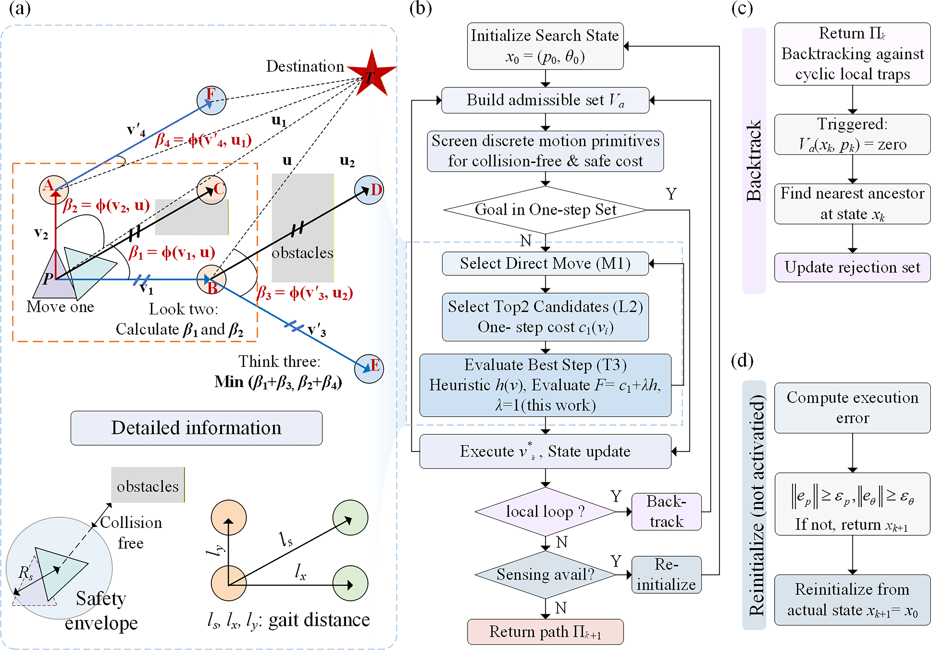
M1L2T3 local planning strategy on the gait-primitive graph.
Figure 6b gives the workflow of the local lightweight planner. It incorporates a backtrack mechanism to handle local loops in Figure 6c and feedback reinitialize mechanism to recover from large errors when sensing is available in Figure 6d. The search state at planning step k is defined by the current support-triangle center and nominal in-plane heading as xk = (pk, θk), where pk ∈ ℝ2 denotes the center of the current support triangle on the local map and θk is the nominal in-plane heading. The gait library is represented as a finite and updated set V, which depends on the friction conditions. Each motion primitive is defined by a nominal terminal displacement, a nominal heading update, and an internal discrete rolling sequence used for feasibility checking. Obstacle checking is performed using a unified circular safety envelope centered at the support-triangle center. The detailed process is given in Supplementary Data and Supplementary Table S3.
Validation and evaluation of planning effects in different maps
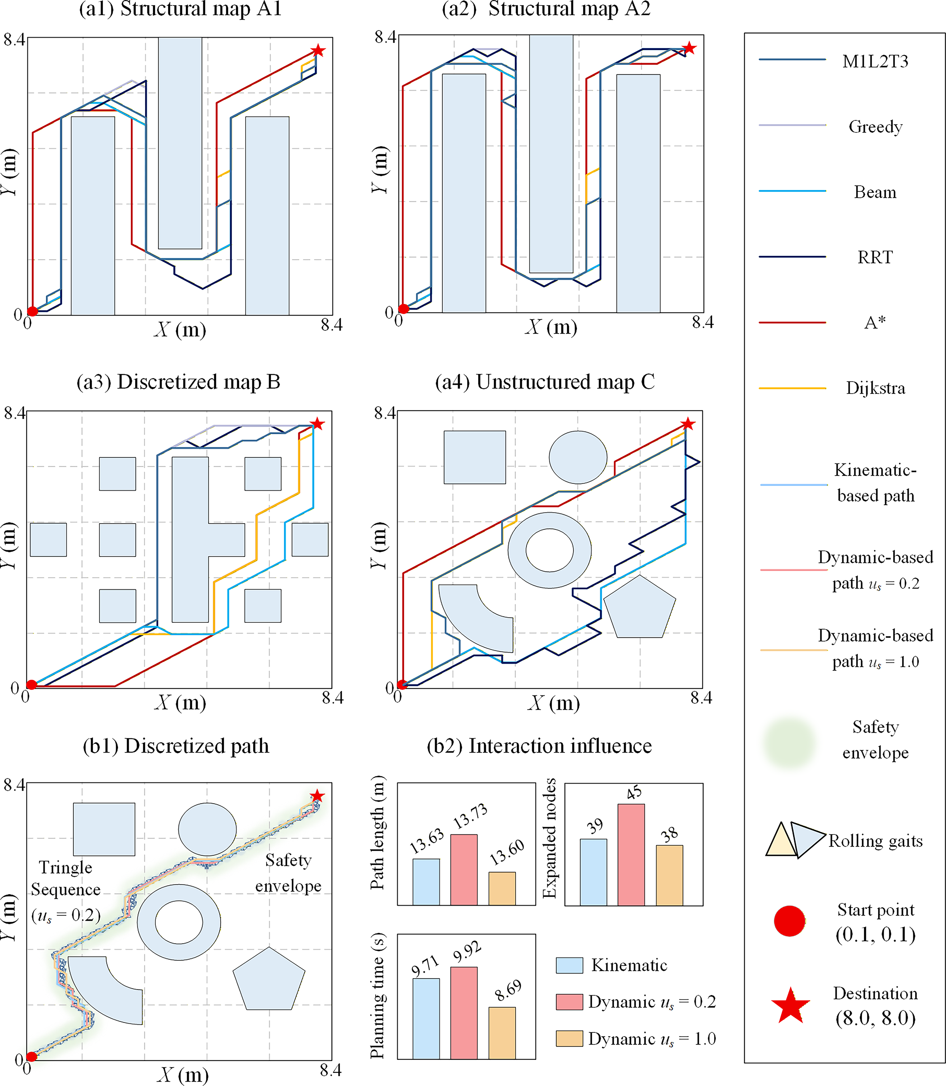
Figure 7 and Table 1 compare the planning performance of M1L2T3 against Greedy best-first search, Beam search, RRT, A*, and Dijkstra on four representative 8.4 m maps, including two structured maps A1 and A2, one discretized map B, and one unstructured map C. The figure also compares kinematic planning with two dynamic modes on the unstructured map, in terms of both the discrete triangle sequence and planning performance under the same safety-envelope coverage.
Planning performance comparison on representative maps. (
Performance Comparison of M1L2T3 with Other Existing Planners
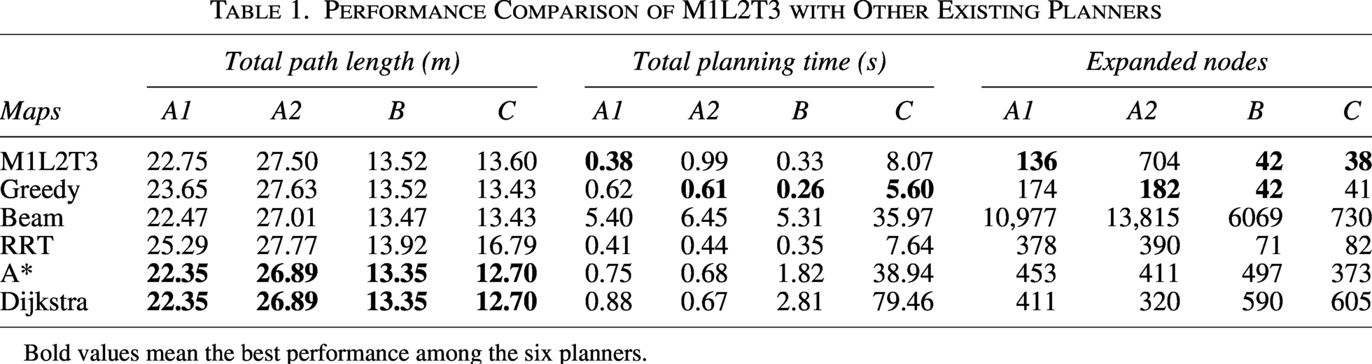
Bold values mean the best performance among the six planners.
A* and Dijkstra generally produce the most compact routes, consistent with the advantage of global graph-search methods in path optimality (Table 1). Although M1L2T3 is not the shortest-path planner, it generates paths that remain close in length to those of the global-search baselines in most cases. Its main advantage lies in its lower computational cost. On maps where feasible corridors are locally aligned with the goal direction, such as A1, B, and C, M1L2T3 performs similarly to the Greedy and reaches the goal with very few expanded nodes.
A limitation of M1L2T3 is also evident. On map A2, where reverse local motion is repeatedly required, its planning time and node-expansion count increase noticeably. Even in that case, it remains substantially more efficient than Beam search. These results align with the intended positioning of M1L2T3, which is a low-computation local heuristic compromise on executable gait primitives, rather than a globally optimal planner.
The comparison on the unstructured map further shows that different friction conditions primarily affect the realized gait geometry and the associated search burden in Figure 7b1 and b2. Differences in total path length are relatively small, while the search effort is not identical. This indicates that different friction conditions influence the local gait geometry and search burden, while the overall planning framework remains effective. This trend is consistent with the friction-dependent step-length behavior observed in Figure 5.
It should be emphasized that the gait-library approach represents a deliberate trade-off, not a claim of universal superiority over optimization- or learning-based methods. Trajectory-optimization methods, MPC, and learning-based policies are all important alternatives, but they typically require greater online computation, tighter model-controller integration, or substantial offline effort for training and validation. The present work targets a different regime, characterized by local map information, a low computational burden, and safety-oriented discrete rolling execution. Under these constraints, interaction-aware gait primitives can be generated offline and called online with modest computational cost. The trade-off of this choice is equally clear: the motion set is discretized, planning performance depends on gait-library quality, and the planner does not guarantee global optimality.
The value of the present approach therefore lies in improving planning–execution consistency under practical constraints, rather than in replacing optimization- or learning-based methods in all scenarios.
Realization of the LTRs
This section delves into the physical prototype and locomotion performances for various equivalent grounds. The detailed manufacturing process, parameters of the robot prototype, and performance comparisons are listed in the Supplementary Data and Supplementary Table S5.
Validation and evaluation of path planning with discrete interactive gaits
Figure 8 presents a path-planning experiment in a 1 × 1 m obstacle map. Figure 8a–c shows the results based on “M1L2T3.” The dynamic-based model generates a path composed of three discrete gaits, namely S1, Y3, and S2, and the prototype successfully reaches the destination. Supplementary Video S1 verifies that the path consists of these three discrete gaits. As shown in Figure 8b, the experimental path agrees well with the dynamic prediction, whereas the kinematic path shows a clear deviation under the same safety envelope. This result indicates that interaction-aware gait primitives improve the consistency between planning and actual execution.
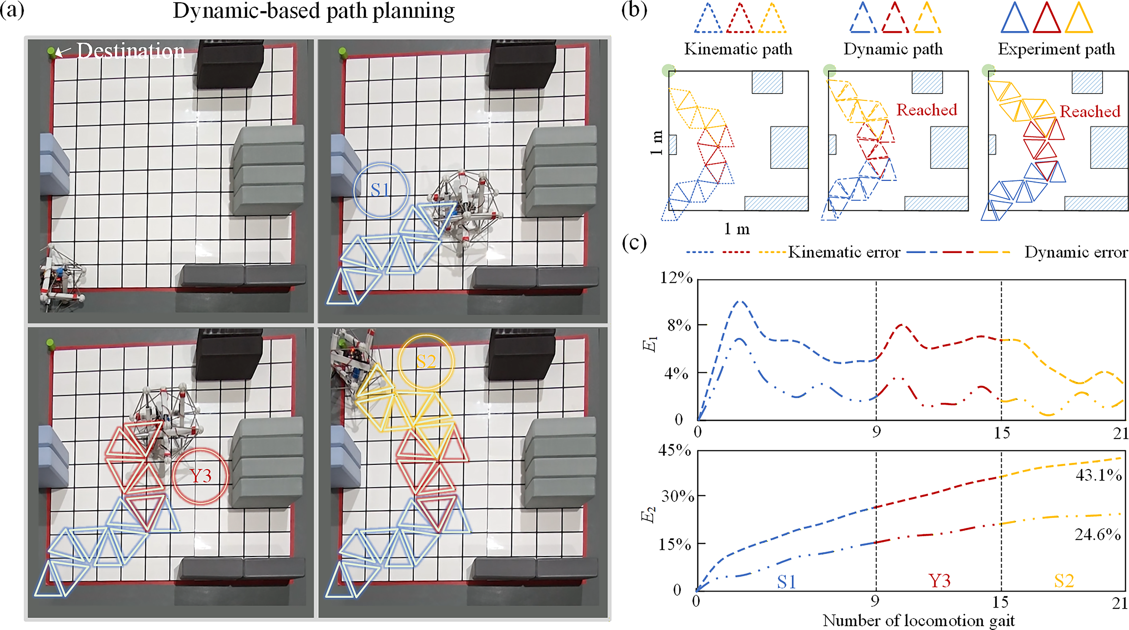
Experimental validation of dynamic-based path planning.
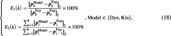
To quantify the predictive accuracy, the COM projection on the ground plane is extracted at the end of each discrete gait. Two error metrics, E1 and E2, are defined to compare the kinematic and dynamic predictions with the experimental results.
Locomotion on different environments
To further test the method in different environments, four representative grounds are considered: grass corresponds to Earth, dry soil to Mars, fine sand to the Moon, and smooth stone to Europa. Before planning, we first measure the friction coefficients μs between the contact points of the LTR and the ground, allowing μs to establish the corresponding gait library. Experiment data are collected using a motion capture system. The dynamic model reflects the slipping behavior of point A in contact with the ground during the initiation or termination of actuation, as evidenced by repeated points at curve inflection regions due to slip. This indicates that the proposed contact-friction-coupled dynamic model captures not only the nominal direction of each discrete rolling gait but also the local trajectory deviations caused by slip, contact-state switching, and terrain-dependent interaction. Thus, after two locomotion presented in Figure 9a and Supplementary Video S2, the dynamics method can be validated.
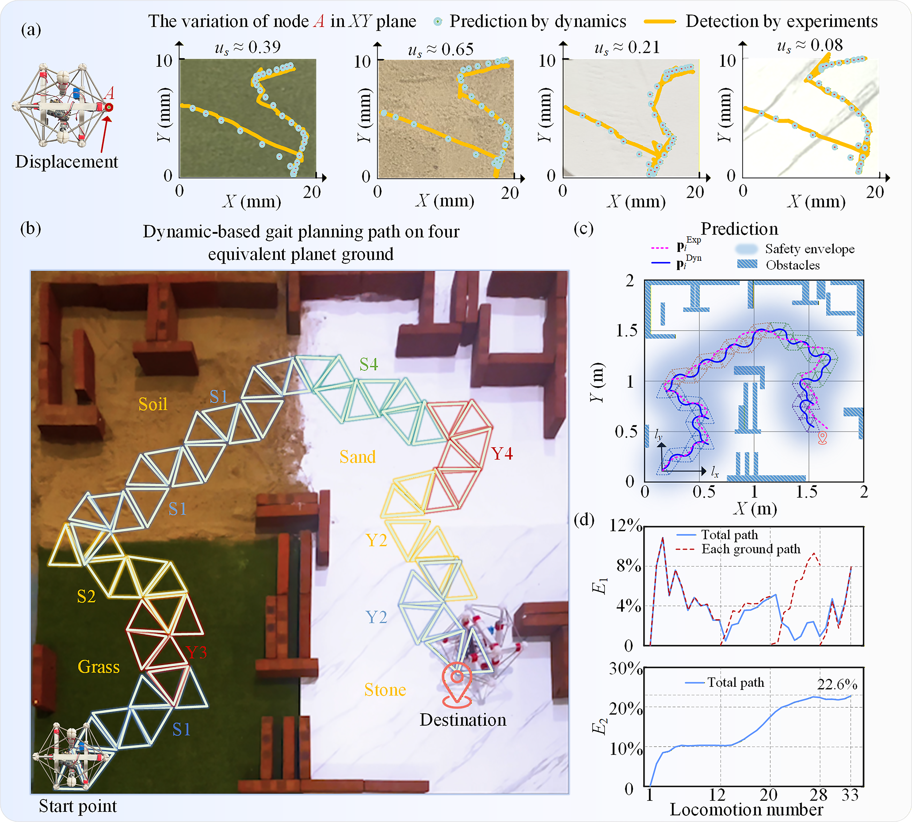
Dynamic-based locomotion planning and validation on four representative equivalent planet grounds.
After obtaining μs, the gait library is used to perform planning on a map (4 × 4 m2) composed of four surface regions in Figure 9b and Supplementary Video S2. Nevertheless, the basic gait pattern remains valid across all ground surfaces. That is, regardless of ground type, as long as the LTR performs movement sequences using basic gaits, the start and end triangles of each gait still approximately correspond to a translational shift. These results confirm that dynamics-based path planning using the gait library is effective.
Figure 9c compares the simulated and experimental COM paths. The blue-shaded area in Figure 9c represents the ranges of the safety envelope. It is only necessary to evaluate whether locomotion is feasible within the blue-shaded area, demonstrating high computational efficiency.
Figure 9d shows the evolution of two error metrics over successive rolling cycles. In the upper panel, the relative gait error E1 fluctuates rather than increasing monotonically. This occurs because E1 captures the instantaneous endpoint discrepancy of each gait, which depends on the current gait direction, contact-switching condition, and local friction properties. In some gaits, deviations accumulated in earlier steps can be partially compensated by subsequent motion, leading to alternating increases and decreases. The gait errors within each terrain segment remain below 12%, indicating good predictive consistency within each terrain segment. Errors are smallest on the high-friction ground, suggesting that the model is more accurate when slipping is weaker. In the lower panel, E2 grows gradually over 33 successive gaits but remains bounded at about 22.6% by the end of the experiment. The result indicates that prediction deviations do accumulate over repeated rolling cycles, yet the accumulation remains moderate over 33 gait sequences.
The main sources of discrepancy between simulation and experiment include uncertainty in friction and contact parameters, calibration error in the contact model, manufacturing and assembly imperfections, actuation inconsistency, motion-capture and COM-extraction error, and idealizations in the dynamic model and gait abstraction. These factors collectively influence the realized rolling path and can accumulate over repeated execution.
Discussion
An important source of discrepancy between the model and experiment is uncertainty in environmental interaction, particularly in contact and friction parameters. To examine this issue, sensitivity analyses are conducted for the friction coefficient μs, contact stiffness K, and damping C under the minimum and maximum friction coefficients (0.08 and 0.65) observed experimentally. These parameters are perturbed within prescribed ranges in Figure 10. Rolling over two representative consecutive gaits is evaluated using the planar locomotion distance and the error metrics E1 and E2. The reference sequence for the two-roll test contains 201 data points.
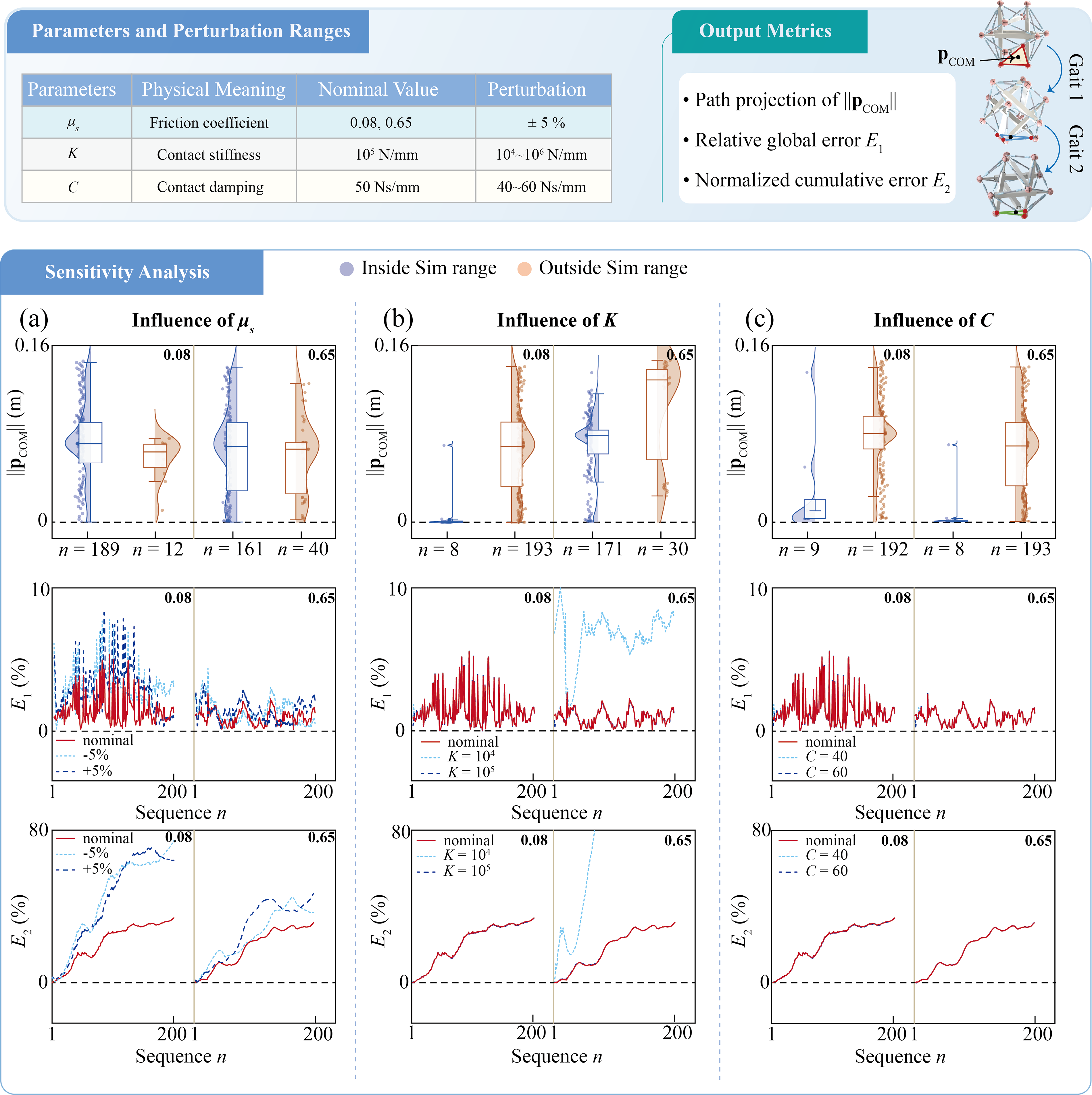
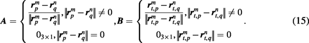
Sensitivity analysis of three interaction parameters under perturbation: friction coefficient μs, contact stiffness K, and contact damping C, together with the output metrics adopted for evaluation during Gait 1 and Gait 2: the projection ‖
For friction uncertainty, simulations with ±5% perturbations show that the predicted trajectories and errors remain within a bounded range around the experimental results. In the lower-friction case, 94% of the experimental points fall within the perturbation band. For higher friction, the proportion of in-band points decreases as the perturbation band becomes narrower, which is consistent with the trend shown in Figure 5. Overall, friction uncertainty leads to only a moderate increase in prediction error. E1 remains below 8%, and the normalized cumulative error over the 200-point sequence remains below 80%. This indicates reasonable robustness to moderate friction variation.
Figure 10b, c further examines the sensitivity to the other two contact parameters. The analyses of contact stiffness and damping reveal a practical trade-off between physical fidelity and numerical stability. Larger stiffness and smaller damping reduce penetration and produce sharper contact response, but they also increase numerical difficulty. Smaller stiffness and larger damping improve solver stability, but they may introduce excessive penetration and distort the rolling behavior. The distributions of the data points show that perturbations have a limited influence on the realized rolling motion. The corresponding uncertainty bands are very narrow, and therefore most experimental points lie outside these bands. The error results are also very close. However, when the contact stiffness is too small, the motion pattern starts to deviate noticeably, the uncertainty band changes abnormally, and both error measures exhibit an unreasonable sharp increase. This indicates that an excessively small contact stiffness leads to distorted rolling behavior. These observations not only support the choice of the nominal contact parameters in this study but also indicate that the rolling trajectory is not highly sensitive to K and C within the valid parameter range; rather, these parameters mainly affect numerical stability and contact fidelity.
More importantly, the results indicate that the proposed interaction-aware dynamic model retains good predictive capability across terrains with different friction coefficients, with accuracy improving as the friction coefficient increases. The strong sensitivity to friction further highlights the necessity of explicitly accounting for ground interaction in trajectory prediction and gait planning. In this sense, planning is physically meaningful only when the locomotion realized under interaction is considered, not when relying solely on idealized kinematic transitions.
Conclusion
This study presents a dynamic-based path-planning framework for a six-bar LTR under environmental interaction. The framework combines three components: an interaction-aware dynamic model, a finite gait library extracted from realized rolling motions, and a lightweight local planner (M1L2T3) defined on the gait-primitive space. The purpose of this work is to improve planning–execution consistency by incorporating contact- and friction-dependent gait realization into the planning process.
The results show that the proposed dynamic model predicts realized locomotion more accurately than an idealized kinematic description. The gait library provides a practical representation of terrain-dependent discrete motion, and the M1L2T3 strategy enables efficient local path selection under limited map information and modest computational cost. Experiments on four representative grounds with different friction conditions further confirm that the predicted paths remain reasonably consistent with the measured robot behavior.
Overall, this work shows that interaction-aware dynamic gait primitives can improve the reliability of gait-based planning for tensegrity robots on terrain-varying surfaces. Future work will focus on broader terrain scenarios, more systematic robustness analysis, and closed-loop replanning with online state feedback. This research marks a significant step forward for tensegrity robots under dynamic environments, paving the way for more advanced and reliable robotic locomotion systems in planet exploration.
Footnotes
Author Disclosure Statement
The authors declare that they have no known competing financial interests or personal relationships that could have appeared to influence the work reported in this article.
Funding Information
The authors would like to gratefully acknowledge the support from the
Supplemental Material
Supplemental Material
Supplemental Material
References
Supplementary Material
Please find the following supplemental material available below.
For Open Access articles published under a Creative Commons License, all supplemental material carries the same license as the article it is associated with.
For non-Open Access articles published, all supplemental material carries a non-exclusive license, and permission requests for re-use of supplemental material or any part of supplemental material shall be sent directly to the copyright owner as specified in the copyright notice associated with the article.