
Abstract
In the present work, a micro-electro-mechanical system (MEMS)-based electrostatic micromotor is designed and fabricated. Finite element analysis is done and various parameters affecting the torque are studied. Maximum torque is achieved at 120° phase angle. The effect of change in voltage, micromotor height and frequency is analysed and discussed. UV-SLIGA, a microfabrication technique, is used for the fabrication of electrostatic micromotor of height 30µm and higher. UV lithography is conducted by both positive AZ P4620 and negative (SU-8 10 and SU-8 2150) photoresists. Copper (Cu) is used as a sacrificial layer to release the rotor (the movable part) of the electrostatic micromotor. Electroformed nickel (Ni) is used for making stator, rotor and axle, whereas chromium (Cr) is used as a seed layer. The micromotor is fabricated with a stator-rotor pole having configuration ratio of 3:2. The gap between the rotor and axle is 20 µm. Wet chemical etching is used to etch the deposited metal layers (Cr, Ni and Cu). Challenges such as the adhesion between the photoresist mould and substrate, cracks, seepage and misalignment are faced during the microfabrication. These challenges are overcome by optimizing the various parameters. The fabrication of electrostatic micromotor is done successfully and the results are discussed in the article.
Keywords
Introduction
Micro-opto-electro-mechanical system (MOEMS) is a miniaturized arrangement where optics is used with electro-mechanical sensors and actuators for novel applications. One such application is the integration of optics with the electrostatic micromotors.1–5 The application of electrostatic micromotors is also extended to gyroscope, 6 optical endoscope 7 and diamagnetic levitation. 8 Recently, a triboelectric micromotor was demonstrated by coupling a triboelectric nanogenerator with an electrostatic micromotor, which is capable of rotating without an external power supply and greatly improves the usability of the electrostatic micromotor as MOEMS. 9
According to the design principle, the electrostatic micromotors are broadly classified as top-drive, 10 side-drive,10–13 wobble14, 15 and induction micromotor. 16 The electrostatic micromotors were first manufactured by integrated-circuit processing where both stator and rotor of these micromotors were fabricated by nearly 1 µm thick poly silicon. 12 In the top-drive electrostatic micromotors, tangential driving forces are developed between the overlapping electrodes on the planar faces of the stator and the rotor. The tangential forces increase with the change in phase of the voltage and the torque is obtained. The normal component of the force becomes destructive for the poles as it forces the rotor to make rough contact with the axle and the base. This is overcome by side-drive micromotors where the tangential driving forces arise from the electrodes on the rotor-stator side walls facing each other when the phase of the voltage changes and torque develops over the cycles. 10 In the wobble micromotor, the rotor rolls along the insulated side wall of the stator, and the resultant torque arises from the tangential component of the electrostatic force generated between the rotor and the stator electrode at the point of contact. Induction micromotors are now being developed due to the limitations like rubbing and wear between the stator and the rotor poles caused by the variable-capacitance micromotors. In these micromotors, the stator and rotor plates are separated by an air gap. The stator plate is coated with a dielectric layer and the rotor plate is coated with a radially distributed conducting layer. When the excitation wave is given to the stator, the charges appear on the dielectric layer and due to this, opposite charges are induced on the rotor plates, which lag behind the charges on the stator plate. Due to the attraction between the opposite charges on both the plates, a tangential component of force arises and the repeated excitation of the tangential component of force gives rise to the torque. 16
The electrostatic micromotors are broadly fabricated by conventional machining, surface micromachining, bulk micromachining and LIGA techniques. ‘LIGA’ is a German acronym for lithography, electroplating and polymer replication. Fujimoto et al. chose the rotor diameter of 5.5 mm of miniature electrostatic motor so that the motor can be fabricated by conventional machining. Both rotor and stator were made of brass. 17 Both bulk and surface micromachining use silicon (Si) as a primary material. In bulk micromachining, the desired microstructures are formed by etching the Si wafer from the back side by wet or dry etching, whereas in surface micromachining, the devices or microstructures are fabricated by the deposition of thin films of metal, polysilicon, silicon nitride and silicon dioxide. Sacrificial layers are integral part of any of the surface micromachining techniques. A detailed comparison and application of both the microfabrication techniques can be found in the literature elsewhere. 18 The electrostatic micromotors are made by both bulk 19 and surface micromachining.11, 20 The micromotor made by Stranczl et al. can be considered as a very good example of a hybrid techniques where both bulk and surface micromachining are used for the microfabrication. 21 During this period, LIGA was also realized as one of the fabrication concepts capable of making very high-aspect ratio microstructures and devices. 22 Both X-rays and ultraviolet (UV) are used for the development of LIGA and termed as X-ray LIGA and UV-LIGA, respectively. LIGA microstructures and devices can be developed from polymer, metal and ceramics. Wallrabe et al. developed electrostatic micromotor by the X-ray LIGA process where Ti was used as a sacrificial layer and motor parts were made of nickel. 13
We at Indus-2 synchrotron radiation (SR) source, at Raja Ramanna Centre for Advanced Technology (RRCAT), are working towards the realization of MOEMS for the manipulation of SR. To achieve this goal, an electrostatic micromotor is designed and fabricated. The design of electrostatic micromotors is governed by output torque, maximum input voltage, number of phases, speed and fabrication technique. The micromotor is fabricated by UV-LIGA and more specifically UV-SLIGA where ‘S’ stands for sacrificial layer. The use of copper as a sacrificial layer in UV-SLIGA is successfully demonstrated in the present work. The state-of-the-art fabrication facilities for the development of MOEMS are currently being developed at our section in RRCAT. Knowing the limitations of fabrication at our place, an MEMS-based electrostatic micromotor is designed and fabricated by UV-SLIGA. The main limitation comes from the mask aligner and flood exposure system. In the present work, electrostatic micromotor is designed, analysed and fabricated by using an in-house developed flood exposure system.
Working principle and design of side-drive electrostatic micromotor
The principal force for driving electrostatic micromotors is the electrostatic force. When voltage is applied across the stator poles and the rotor is kept at ground or floating potential, an electric field is established between stator and rotor poles. Due to this field, an electrostatic force with radial and tangential components is developed. The radial component pushes the rotor towards the stator poles whereas the tangential component gives the rotor a sideways/rotary movement. Furthermore, when voltage is applied across the next pair of the stator poles followed by the remaining stator pole sets, the tangential component of the force dominantly increases in comparison to the radial component, resulting in an output torque.
13
The torque, T (θ), in the case of variable capacitance micromotors is evaluated using Equation (1). The effects of fringe fields, friction between the rotor and axle and air drag are neglected.
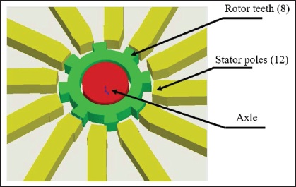
where V represents the applied voltage, C represents the capacitance and θ angular position of the rotor in radians. The dimensions of the micromotor are selected by keeping in mind the limitations of LIGA and associated in-house facilities. The device consists of a rotor with internal and external diameters (extended up to rotor poles or teeth) of 540 µm and 800 µm (990 µm), respectively. Knowing the advantages of three and higher phase power supplies, the stator and the rotor pole ratio is fixed as 3:2. 23 The rotor consists of 8 poles which are equally separated at an angle of 27° and the angular pole width is 18°. There are 12 stator poles which are separated equally at an angle of 12° and the angular pole width is 18°. There is an axle on which rotor is supported and its diameter is selected as 500 µm. The airgap between rotor and stator poles is kept as 30 µm, whereas the gap between the axle and the rotor is taken as 20 µm (refer Figure 1). The stator poles are extended further to form square-shaped contact pads of cross-section 1.5 mm × 1.5 mm. The depth or height of the micromotor is selected as 30–800 µm.
Isometric view of electrostatic micromotor where axle, rotor and stator are shown. There are 8 teeth in rotor, 12 teeth in stator which provides 3:2 stator and rotor pole ratio.
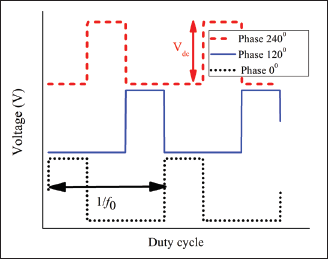
The finite element analysis (FEA) of micromotor is carried out on COMSOL Multiphysics 5.6. The ‘electromechanics’ physics and ‘time dependent’ study are used to simulate the response of micromotor in COMSOL Multiphysics. All the input square waves with their respective duty cycle, angular frequency, phase angle and amplitude are defined using ‘Waveform’ function in ‘Definition’ section. For example, at 120° phase difference, duty cycle is 1/3 and excitation scheme for an anti-clockwise rotation will be same, as shown in Figure 2. The excitation scheme for the other phase angles (refer Figure 3) will follow the similar approach where all the waveforms will be accommodated for a given time period (1/f0). This will decide the duty cycle for a particular phase. In this way, for 30°, 60°, 90° and 180° phase difference, the duty cycle will be 1/12, 1/6, 1/4 and 1/2, respectively. The time-dependent study in COMSOL Multiphysics is initialized with a stationary study to remove the inconsistency of input supply at stator. The excitation voltages (square wave) with a necessary phase difference are defined in the ‘global definition’. Following this, geometry of the micromotor is made as discussed in Section 2 and shown in Figure 1. The boundaries and domains are defined followed by the selection of materials for different domains. Here, Ni is taken for the stator and rotor poles and air is selected for the airgaps (dielectric media). The rotor is kept at floating potential. Mesh convergence is done in order to decide the optimum size of the meshing element for stator, rotor and air domains. Free quad element of size 25 µm is used for the meshing/discretization of stator and rotor of the micromotor and free tetrahedral element of size 25 µm is used for the meshing/discretization of air domain. Five element distribution is done for the discretization of elements along the thickness of the stator and the rotor for the better results. Serendipity approach is used to define the shape functions of the elements used for meshing the entire geometry. The necessary mechanical boundary conditions are defined where stator poles are fixed and displacement of rotor at the centre of rotation in all the three direction is fixed at zero. Only rotation around z-axis is allowed. The voltage excitation is applied for stationary and time-dependent solvers, respectively. To overcome the inertia, a DC voltage is applied in a sequence.
Excitation scheme of electrostatic micromotor with 120° phase difference.
Excitation scheme of electrostatic micromotor with 120° phase difference.
The possible phase angle configurations for 3:2 side-drive electrostatic micromotor: (a) phase angle is 30° which provides total 12 phases; (b) phase angle is 60° which provides total 6 phases; (c) phase angle is 90° which provides total 4 phases; (d) phase angle is 120° which provides total 3 phases; (e) phase angle is 180° which provides total 2 phases.
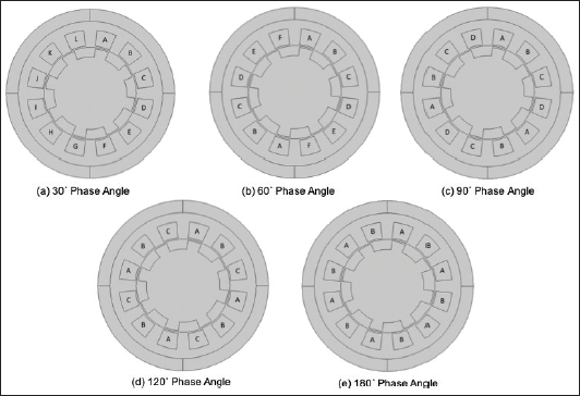
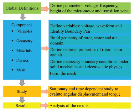
As discussed in Section 2, to gain maximum torque, the ratio between the number of stator poles to the number of rotor poles is taken as 3:2. The possible phase excitation sequences of the micromotor are mentioned in Figure 3. The phase angle configurations for 3:2 side-drive electrostatic micromotor are as follows: (a) phase difference is 30° between the two stator poles which includes total 12 phases; (b) phase difference is 60° between the two stator poles which includes total 6 phases; (c) phase difference is 90° between the two stator poles which includes total 4 phases; (d) phase difference is 120° between the two stator poles which includes total 3 phases; (e) phase difference is 180° between the two stator poles which includes total 2 phases. Process flow used for FEA of electrostatic micromotor in COMSOL Multiphysics is summarized in Figure A1 of Appendix A. Material properties and the parameters used for FEA of electrostatic micromotor in COMSOL Multiphysics are given in Table B1 of Appendix B.
The electrostatic micromotor is fabricated by the UV-SLIGA process. The details of fabrication are given in Sections 4.1 and 4.2.
Experimental
The basic steps involved in the fabrication of electrostatic micromotor by UV-SLIGA are substrate cleaning; physical vapour deposition of Cr, Ni and Cu; spin coating of positive AZ P4620 and negative (SU-8 10 and SU-8 2150) photoresists; pre-baking; UV flood exposure, post-exposure baking; development of SU-8 microstructure in the developer; electroforming of Ni; and removal of Cu sacrificial layer. Three different UV masks are made using laser pattern generator (Heidelberg DWL200, Germany) for the development of micromotor by UV-SLIGA process. Ion beam and DC magnetron sputtering techniques are used for the deposition of Cr, Ni and Cu over cleaned alumina substrates. The spin coating is done on LabSpin 6TT (SUSS MicroTec, Germany). The pre- and post-baking of photoresists are performed in hotplate (LabTech, India). The UV exposure is done using in-house-developed flood exposure system and mask aligner. The UV source is a broadband UV lamp (OSRAM, Ultra VITALUX 300 W, USA). For agitation, ultrasonic cleaner (Imeco, ICW (P) Ltd., India) is used.
Process flow for fabrication of micromotor
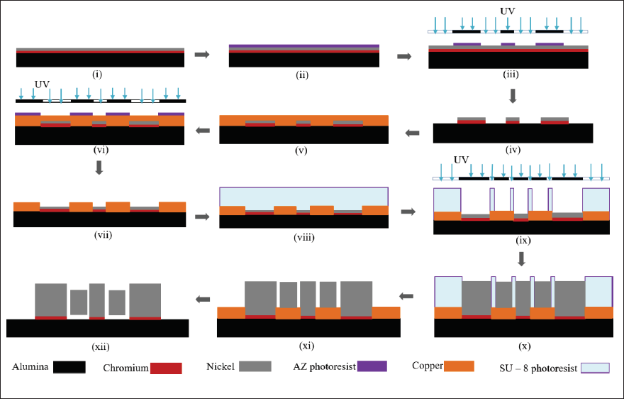
The process flow exhibiting the stages of development of electrostatic micromotor by UV-SLIGA is shown in Figure 4. Inorganic and organic impurities from alumina wafer are cleaned in 20% HF, acetone, isopropyl alcohol and DI water in separate steps in ultrasonic cleaner. The steps of the process flow are as follows: (i) 100 nm Cr and 400 nm Ni are deposited using ion beam sputtering for the formation of bottom electrodes; (ii) for patterning of Ni and Cr, 8-µm-thick positive photoresist AZ P4620 is coated with the help of spin coater and baked at the hotplate at 110°C for 3 minutes; (iii) UV flood exposure is done with the help of photomask-1 followed by the development of positive photoresist; (iv) selective etching of Ni and Cr are done in 50% nitric acid, 10.9% ceric ammonium nitrate and 4.25% perchloric acid; (v) 4 µm thick Cu (sacrificial layer) is deposited by DC magnetron sputtering over patterned alumina wafer; (vi) the coating of positive photoresist is done over deposited Cu sacrificial layer using spin coater and after baking UV exposure is done with the help of aligned photomask-2 for patterning of the Cu sacrificial layer (here, the photomask-2 is aligned with the help of an in-house developed mask aligner); (vii) the selective etching of patterned Cu sacrificial layer is done by ammonium persulphate; (viii) 30 µm and 150 µm thick coating of negative photoresist (SU-8) is done for the formation of rotor and stator mould; (ix) UV exposure is done with the help of aligned photomask-3 for the optimized time, and the development is done to form the rotor and the stator patterns in the form of SU-8 mould; (x) electroforming of 30 µm and 150 µm thick Ni is done by nickel sulfamate solution at 55 °C; (xi) after electroforming, SU-8 mould is removed carefully by PG remover; and (xii) sacrificial layer of Cu is removed and micromotor of Ni is formed. The influence of the processes on the fabrication of electrostatic micromotor is discussed in Section 5.2 in detail.
Process flow showing the stages of development of electrostatic micromotor by UV-SLIGA: (i) alumina wafer coated with Cr and Ni for the formation of bottom electrode; (ii) AZ photoresist coated for patterning of Ni and Cr; (iii) UV flood exposure with the help of photomask-1 followed by the development of positive photoresist; (iv) selective etching of Ni and Cr; (v) Cu (sacrificial layer) deposition over patterned wafer; (vi) coating of AZ photoresist followed by UV exposure with the help of aligned photomask-2; (vii) selective etching of Cu sacrificial layer; (viii) coating of SU-8 negative photoresist for the formation of rotor and stator mould; (ix) UV exposure with the help of aligned photomask-3; (x) electroforming of thick Ni; (xi) removal of SU-8 mould; and (xii) removal of sacrificial layer and drying. The numbering to the various processes of process flow is kept same as in the description of Section 4.2 for better readability.
Process flow showing the stages of development of electrostatic micromotor by UV-SLIGA: (i) alumina wafer coated with Cr and Ni for the formation of bottom electrode; (ii) AZ photoresist coated for patterning of Ni and Cr; (iii) UV flood exposure with the help of photomask-1 followed by the development of positive photoresist; (iv) selective etching of Ni and Cr; (v) Cu (sacrificial layer) deposition over patterned wafer; (vi) coating of AZ photoresist followed by UV exposure with the help of aligned photomask-2; (vii) selective etching of Cu sacrificial layer; (viii) coating of SU-8 negative photoresist for the formation of rotor and stator mould; (ix) UV exposure with the help of aligned photomask-3; (x) electroforming of thick Ni; (xi) removal of SU-8 mould; and (xii) removal of sacrificial layer and drying. The numbering to the various processes of process flow is kept same as in the description of Section 4.2 for better readability.
Observations from finite element analysis of electrostatic micromotor
The FEA is conducted to study the variation of rotor’s torque with respect to the governing parameters, namely phase angle, voltage, excitation frequency and height of the rotor.
Phase angle and its effect on torque
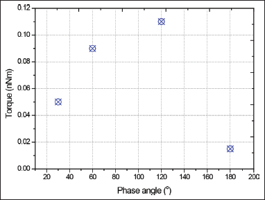
As shown in Figure 5, for any excitation sequence with phase difference of 120°, the maximum number of stator and rotor poles completely overlaps and this produces maximum and uniform torque in 3:2 micromotor configuration when compared with the other phase angles. A detailed discussion on the advantages of 3:2 rotor-stator configuration can be found in the literature elsewhere. 23 It is evident from Figure 3 and the FEA results that maximum torque is obtained at 120° where maximum positive torque is achieved due to better motor torque coverage.
Change in torque with phase angle where all the values are calculated for 100 V, 100 Hz and 30 µm height of rotor.
Change in torque with phase angle where all the values are calculated for 100 V, 100 Hz and 30 µm height of rotor.
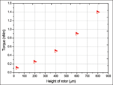
It is evident from Equation (1) that the magnitude of torque is directly proportional to the rate of change of capacitance with respect to rotor position (θ). Furthermore, the capacitance is directly proportional to the projected area. To estimate the output torque for the rotor and the stator heights varying from 30 µm to 800 µm, FEA is done. It is shown in Figure 6 that the greater aspect ratio of the electrostatic micromotor will provide the higher torque. For 30 µm and 800 µm height, the torque is nearly 0.11 nNm and 1.4 nNm, respectively at 120° phase angle, 100 V excitation voltage and 100 Hz frequency. Both DC and Square waves are applied to produce the torque.
Change in torque with rotor height where all the values are calculated for 100 V, 100 Hz and 120° phase angle for 30 μm rotor height.
Change in torque with rotor height where all the values are calculated for 100 V, 100 Hz and 120° phase angle for 30 μm rotor height.
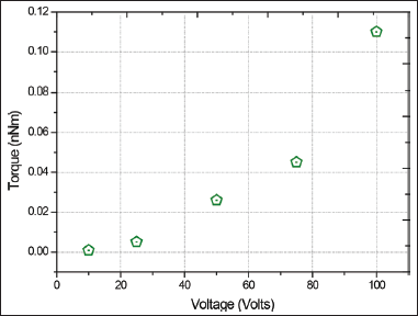
In an electrostatic motor, the torque is proportional to the voltage (considering it as time independent variable). The simulation is performed to estimate the torque values for different voltages. Torque as a function of applied voltage is plotted in Figure 7. For 30 µm rotor height and the excitation voltage of 10 V and 100 V at 100 Hz and 120° phase angle, the torque is 0.8 pNm and 1.4 nNm, respectively.
Change in torque with input voltage where all the values are calculated for 100 Hz, 120° phase angle and 30 μm height of rotor.
Change in torque with input voltage where all the values are calculated for 100 Hz, 120° phase angle and 30 μm height of rotor.
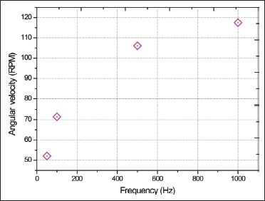
Figure 8 shows the variation of the angular velocity at different frequencies. At 50 Hz, angular velocity is 52 rpm. The angular velocity increases as the frequency increases. At 1 kHz, the angular velocity is 117 rpm.
Change in angular velocity with frequency where all the values are calculated for 100 V, 120° phase angle and 30 μm height of rotor.
Change in angular velocity with frequency where all the values are calculated for 100 V, 120° phase angle and 30 μm height of rotor.
The fabrication of electrostatic micromotor by UV-SLIGA or any other MEMS techniques is quite challenging and requires dedicated tools, for example, double-sided mask aligner. In the present case, the microfabrication is attempted with the in-house support. The UV flood exposure system and mask aligner are built in-house and electroforming is performed in a simple lab set-up. The use of Cu as a sacrificial layer for the development of micromotor by UV-SLIGA is another value addition. The results are interesting and various parameters influencing the fabrication of electrostatic micromotor are discussed here.
Cracks during UV flood exposure
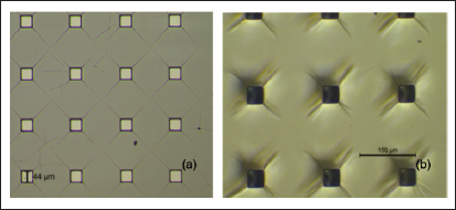
SU-8 is a very sensitive negative photoresist and its performance is greatly influenced by the selection of wavelength. 24 The UV source in the in-house developed flood exposure system is a broadband source and imposes the limitation on dimensional accuracy. The optimization of the exposure time is done to obtain the dimensions closer to the photomask. The crack propagation in SU-8 microstructures is increased as we tried to get closer to the dimensions in the photomask mainly due to insufficient UV dose. This leads to stress generation over the top layer. The cracks in both SU-8 10 and SU-8 2150 are shown in Figure 9. This issue is resolved by increasing the exposure dosage over the coated resists on the cost of the dimensions of micromotor. The dimensions are obtained with errors of 2 µm and 5 µm for SU-8 10 and SU-8 2150, respectively.
The generation of cracks in the microstructures of (a) SU-8 10 and (b) SU-8 2150 during the optimization of exposure time for achieving the dimensions same as photomask. The squares are developed regions and rest is SU-8 where cracks are visible.
The generation of cracks in the microstructures of (a) SU-8 10 and (b) SU-8 2150 during the optimization of exposure time for achieving the dimensions same as photomask. The squares are developed regions and rest is SU-8 where cracks are visible.
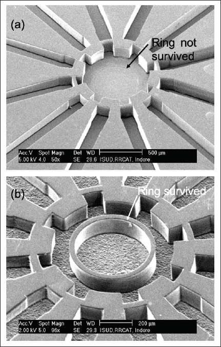
In addition, inadequate adhesion of the SU-8 microstructures with the substrate is another issue faced during the optimization of the exposure time for the development of micromotor. In the present work, SU-8 mould is fabricated over Cu sacrificial layer for which SU-8 must strongly adhere on Cu. As shown in Figure 10, (a) ring separating the rotor and axle was not sustaining due to insufficient bottom dose. The use of adhesion promoter was also inefficient in providing the necessary adhesion of the ring. It should be noted that the other region of the mould due to larger dimensions adhered well with the Cu for the same exposure time (refer Figure 10). The exposures doses are further increased for the sustenance of the ring which again resulted in the deviation in the dimensions to nearly 5 µm for SU-8 10 and 10 µm for SU-8 2150 when compared with dimensions in the photomask.
The micromotor mould in SU-8 2150 resist; (a) the ring separating the rotor and axle did not sustain due to insufficient bottom dose. The other region of the mould due to larger dimensions adhered well with the Cu for the same exposure time; (b) the ring survived when exposure dose is increased. Here, the ring thickness is increased to 30 μm instead of designed 20 μm.
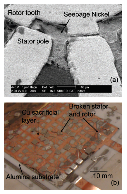
The electroforming of Ni is done on both 30 µm and 150 µm thick SU-8 moulds. Due to the insufficient adhesion, as discussed in Section 5.2.1, the seepage of Ni is observed in the Ni microstructures of micromotor (refer Figure 11a). The problem of seepage is not observed for the SU-8 microstructures with enhanced UV doses. Furthermore, as shown in Figure 11b, the high aspect ratio Ni microstructures (150 µm high) did not survive. This is mainly due to the excessive stresses on the Ni microstructures due to swelling when SU-8 is kept in the PG remover. Due to this reason, it is decided to work with 30 µm high microstructures of micromotor. In addition, pitting in Ni microstructures is avoided by controlling the process parameters.
(a) Due to poor adhesion, seepage of Ni is observed in between rotor and stator Ni microstructures of micromotor; (b) collapsing of 150-μm-high Ni microstructures due to excessive stress. 50 mm × 50 mm alumina substrate carries 4 um Cu sacrificial layer is also shown.
(a) Due to poor adhesion, seepage of Ni is observed in between rotor and stator Ni microstructures of micromotor; (b) collapsing of 150-μm-high Ni microstructures due to excessive stress. 50 mm × 50 mm alumina substrate carries 4 um Cu sacrificial layer is also shown.
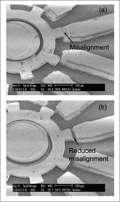
The accurate alignment of the different layers during processing is very crucial for the smooth working of the electrostatic micromotor and similar MEMS devices. As mentioned earlier, unlike a professional mask aligner, in the present case, the alignment is done with the help of in-house-developed mask aligner. Any misalignment between rotor and stator, as shown in Figure 12a, will defeat the sole purpose of developing electrostatic micromotor. The alignment marks were carefully observed during the alignment of two different layers. It should be noted that alignment marks are same in all the photomasks and, second and third layers are aligned with respect to the first layer. The problem of misalignment was reduced by careful and repetitive iterations. The developed electrostatic micromotor is shown in Figure 12b.
(a) The bottom electrode is touching the rotor due to misalignment; (b) by careful alignment, the contact between bottom electrode and rotor is avoided. In both the cases, the rotor is free to rotate mechanically. Only case (b) is electrically viable.
(a) The bottom electrode is touching the rotor due to misalignment; (b) by careful alignment, the contact between bottom electrode and rotor is avoided. In both the cases, the rotor is free to rotate mechanically. Only case (b) is electrically viable.
The rotor of the micromotor is released mechanically, and it confirmed the success of the UV-SLIGA process. The pads of the stators are bonded with the wire for the characterization of the electrostatic micromotor.
At RRCAT, we are working towards the realization of MOEMS for the manipulation of SR. When working to achieve this goal, an electrostatic micromotor is designed, analysed and fabricated. For designing the stator and rotor pole, the ratio is fixed as 3:2 so that the motor can be rotated bidirectionally. The dimensional parameters of the micromotor are chosen by keeping in mind the limitations associated with the fabrication.
FEA of electrostatic micromotor is conducted in COMSOL Multiphysics 5.6. Various parameters such as height of the rotor (motor), phase angle, frequency and voltage are studied against the output torque. For 30 µm rotor height and the excitation voltage of 10 V and 100 V at 100 Hz and 120° phase angle, the torque is 0.8 pNm and 1.4 nNm, respectively. Similarly, for 30 µm and 800 µm height, the torque is nearly 0.11 nNm and 1.4 nNm, respectively at 120° phase angle, 100 V excitation voltage and 100 Hz frequency. At 50 Hz and 1 kHz, the angular velocities are 52 rpm and 117 rpm, respectively, for 100 V, 30 µm rotor height and 120° phase angle.
The fabrication is done by UV-SLIGA in the in-house-developed low cost UV flood exposure system and mask aligner. The use of Cu as a sacrificial for the fabrication of electrostatic micromotor is quite unusual and successfully demonstrated in the present work. The issues of cracks in SU-8 mould are addressed by increasing the UV exposure dose. For sustenance of the critical parts like ring between the axle and rotor, the exposure dose is further increased. Poor adhesion also resulted in the seepage during Ni electroforming. By increasing the exposure dose, the cracks are eliminated and adhesion of the resist with the substrate is improved. This is achieved on the cost of dimensional accuracy and the deviations of 5 µm and 10 µm are seen for 30 µm high (by SU-8 10) and 150 µm high (by SU-8 2150) micromotor moulds, respectively.
The development of high aspect ratio micromotor is quite challenging due to the generation of stresses in the Ni microstructures. The stresses are generated due to swelling of SU-8 mould during development. For this reason, only 30 µm high micromotor is developed. The issue of misalignment and Cu sacrificial layer is carefully handled and the electrostatic micromotor is fabricated by UV-SLIGA. The facilities for the characterization of the electrostatic micromotor are currently being developed. The micromotor will be characterized in the near future.
Appendix A
Process flow used for FEA of electrostatic micromotor in COMSOL Multiphysics is summarized in the following flow diagram:
Appendix B
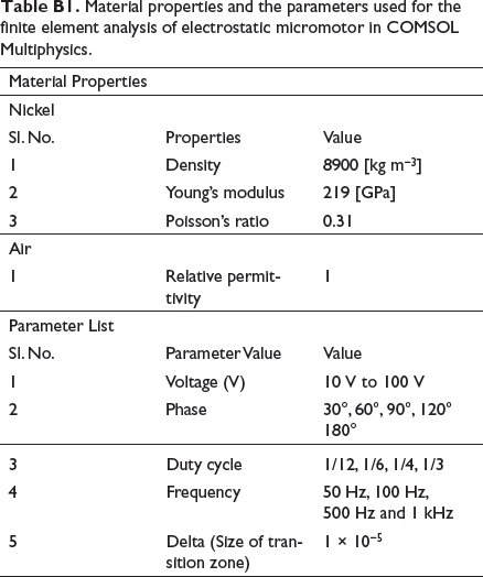
Material properties and the parameters used for the finite element analysis of electrostatic micromotor in COMSOL Multiphysics.
Footnotes
Acknowledgement
The authors greatly acknowledge the support of workshop-B in fabricating many of the components of in-house-developed UV flood exposure system and mask aligner. PRS and GB are thankful to Shri Ganesh Shankar Deshmukh for helping in electroforming of Ni. RS greatly acknowledges the support and necessary help of Tapas Ganguli, Head, SUS for realizing the micromotor. AD and RS are thankful to Dhananjai Pandey for timely support, necessary for realizing the micromotor. FEM simulation in COMSOL Multiphysics 5.6 is supported by High-Performance Computing Cluster Kshitij-5 of Computer Division and thankfully acknowledged.
Author Note
A. K. Sinha is presently affiliated to Department of Physics, School of Engineering, University of Petroleum and Energy Studies, Dehradun, India.
Declaration of conflicting interests
The authors declared no potential conflicts of interest with respect to the research, authorship and/or publication of this article.
Funding
This research work is supported by Department of Atomic Energy, Government of India. The authors received no financial support for publication of this article.